1
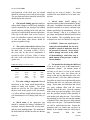
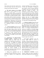
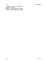
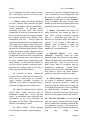
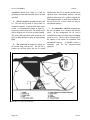
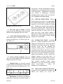
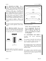
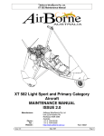
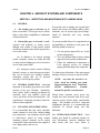
9/27/01 AC 43.13-1B CHG 1 CHAPTER 9. AIRCRAFT SYSTEMS AND COMPONENTS SECTION 1. INSPECTION AND MAINTENANCE OF LANDING GEAR 9-1. GENERAL. a. The landing gear on aircraft may be fixed or retractable. A fixed gear may be wheels, floats, or skis; and for amphibians a combination of floats and wheels. b. Retractable gear on aircraft is usually operated with hydraulic or electric power, although some models of light general aviation aircraft have manual retract systems operated by a lever in the cockpit. (1) In addition to the normal operating system, emergency systems are usually provided to ensure that the landing gear can be lowered in case of main-system failure. (2) Emergency systems consist of backup hydraulic systems, or stored nitrogen gas bottles that can be directed into actuating cylinders, mechanical systems that can be operated manually, or free-fall gravity systems. 9-2. GENERAL INSPECTION. A thorough inspection of the landing gear involves the entire structure of the gear, including attachments, struts, wheels, brakes, actuating mechanisms for retractable gears, gear hydraulic system and valves, gear doors, and all associated parts. The manufacturer’s inspection procedures should be followed where applicable. 9-3. CLEANING AND LUBRICATING. It is recommended that only easily removable neutral solutions be used when cleaning landing gear components. Any advantage, such as speed or effectiveness, gained by using cleaners containing corrosive materials, can be quickly counteracted if these materials become trapped in close-fitting surfaces and crevices. Par 9-1 Wear points, such as landing gear up-and-down latches, jack-screws, door hinges, pulleys, cables, bellcranks, and all pressure-type grease fittings, should be lubricated after every cleaning operation. To prevent possible failure of a component due to incompatibility or breakdown of the grease, the following should be observed: 1. Use only greases approved for use by the product manufacturer. 2. Never mix different kinds of grease without approval from the product manufacturer. 3. Follow the manufacturer’s instructions or FAA approved process for cleaning, purging, and lubricating of the component. To obtain proper lubrication of the main support bushings, it may be necessary to jack the aircraft. NOTE: Any time the aircraft is on jacks, check the landing gear main support bushings for wear. Consult the aircraft manufacturer’s overhaul manual for specific wear tolerances. During winter operation, excess grease may congeal and cause increased loads on the gear retraction system, electric motors, and hydraulic pumps. This condition can lead to component malfunctions; therefore, it is recommended that cleanliness be stressed during and after lubrication. 9-4. FIXED-GEAR INSPECTION. Fixed landing gear should be examined regularly for wear, deterioration, corrosion, alignment, and other factors that may cause failure or Page 9-1 AC43.13-1B CHG 1 9/27/01 unsatisfactory operation. During a 100-hour or an- Page 9-2 Par 9-8 AC 43.13-1B CHG 1 9/27/01 nual inspection of the fixed gear, the aircraft should be jacked up to relieve the aircraft weight. The gear struts and wheels should be checked for abnormal play and corrected. a. Old aircraft landing gear that employs a rubber shock (bungee) cord for shock absorption must be inspected for age, fraying of the braided sheath, narrowing (necking) of the cord, and wear at points of contact with the structure and stretch. If the age of the shock cord is near 5 years or more, it is advisable to replace it with a new cord. A cord that shows other defects should be replaced, regardless of age. b. The cord is color-coded to indicate when it was manufactured and to determine the life of the shock cord. According to MIL-C-5651A, the color code for the year of manufacture is repeated in cycles of 5 years. Table 9-1 shows the color of the code thread for each year and quarter year. TABLE 9-1. Bungee cord color codes. YEARS ENDING WITH COLOR QUARTER COLOR 0 or 5 1 or 6 2 or 7 3 or 8 4 or 9 Black Green Red Blue Yellow 1st 2nd 3rd 4th 1st Red Blue Green Yellow Red c. The color coding is composed of threads interwoven in the cotton sheath that holds the strands of rubber cord together. Two spiral threads are used for the year coding and one thread is used for the quarter of the year sheath, e.g. yellow and blue would indicate that the cord was manufactured in 1994 during April, May, or June. d. Shock struts of the spring-oleo type should be examined for leakage, smoothness of operation, looseness between the moving parts, and play at the attaching points. The extension of the struts should be checked to make sure that the Page 9-2 springs are not worn or broken. The piston section of the strut should be free of nicks, cuts, and rust. e. Air-oil struts should undergo an inspection similar to that recommended for springoleo struts. In addition, the extension of the strut should be checked to see that it conforms to the distance specified by the manufacturer. If an airoil strut “bottoms”—that is, it is collapsed—the gas charge and hydraulic fluid has been lost from the air chamber. This is probably due to a loose or defective air valve or to defective O-ring seals. CAUTION: Before an air-oil strut is removed or disassembled, the air valve should be opened to make sure that all air pressure is removed. Severe injury and/or damage can occur as the result of disassembling a strut when even a small amount of air pressure is still in the air chamber. f. The method for checking the fluid level of an air-oil strut is given in the manufacturer’s maintenance manual. An alternate means of servicing an oil strut is to jack up the aircraft, remove the strut’s valve cap, release the air charge in the strut by depressing the valve core, remove the strut’s valve core, attach a clean twofoot rubber or plastic hose to the threaded portion that houses the valve core, and secure with a hose clamp. Put the other end of the hose into a clean two quart container filled with the correct hydraulic fluid for the strut. Cover the container with a clean rag to prevent spillage. Now, slowly raise the gear/strut assembly either manually or with another jack under the strut. This will drive the remaining air out of the strut into the container of hydraulic fluid. Once the gear is fully retracted, slowly lower the gear. The hydraulic fluid in the can will be sucked into the strut. Repeat this procedure until you cannot hear any more air bubbles in the container when the wheel strut is fully retracted. With the strut Par 9-4 9/27/01 fully retracted, remove the hose, insert the valve core, lower the gear, and service the strut with nitrogen to get the proper strut extension. g. The entire structure of the landing gear should be closely examined for cracks, nicks, cuts, corrosion damage, or any other condition that can cause stress concentrations and eventual failure. The exposed lower end of the air-oleo piston is especially susceptible to damage and corrosion, which can lead to seal damage, because the strut is compressed and the piston moves past the strut lower seal, causing the seal to leak fluid and air. Small nicks or cuts can be filed and burnished to a smooth contour, eliminating the point of stress concentration. If a crack is found in a landing-gear member, the part must be replaced. h. All bolts and fittings should be checked for security and condition. Bolts in the torque links and shimmy damper tend to wear and become loose due to the operational loads placed on them. The nose-wheel shimmy damper should be checked for proper operation and any evidence of leaking. All required servicing should be performed in accordance with the aircraft service manual. AC 43.13-1B CHG 1 operation of indicating systems, clearance of tires in wheel wells, and operation of landing-gear doors should be checked. Improper adjustment of sequence valves may cause doors to rub against gear structures or wheels. The manufacturer’s checklist should be followed to ensure that critical items are checked. While the aircraft is still on jacks, the gear can be tested for looseness of mounting points, play in torque links, condition of the inner strut cylinder, play in wheel bearings, and play in actuating linkages. Emergency blow down gear bottles should be inspected for damage and corrosion and weighed to see if the bottle is still retaining the charge. b. Mechanics should be aware that retread tires can be dimensionally bigger than a “new” tire. While this does not pose a problem on fixed landing gear aircraft, it may present a serious problem when installed on retractable landing gear aircraft. It is strongly recommended that if a retread tire is installed on a retractable landing gear aircraft, a retraction test be performed. With the gear in the up-and-lock position, the mechanic should determine that if the tire expands due to high ambient temperature, heat generated from taxi and take-off, repeated landings, or heavy braking, the tire will not expand to the point that it becomes wedged in the wheel well. 9-5. INSPECTION OF RETRACTABLE LANDING GEAR. Inspection of the retractable landing gear should include all applicable items mentioned in the inspection for the fixed gear. In addition, the actuating mechanisms must be inspected for wear looseness in any joint, trunnion, or bearing; leakage of fluid from any hydraulic line or unit; and, smoothness of operation. The operational check is performed by jacking the aircraft according to the manufacturer’s instructions and then operating the gear retracting and extending system. c. The proper operation of the antiretraction system should be checked in accordance with the manufacturer’s instructions. Where safety switches are actuated by the torque links, the actual time of switch closing or opening can be checked by removing all air from the strut and then collapsing the strut. In every case, the adjustment should be such that the gear control cannot be placed in the UP position or that the system cannot operate until the shock strut is at the full extended position. a. During the operational test, the smoothness of operation, effectiveness of up-anddown locks, operation of the warning horn, 9-6. EMERGENCY SYSTEMS. Exercise emergency landing gear systems periodically to ensure proper operation and to prevent inactivity, Par 9-4 Page 9-3 9/27/01 AC 43.13-1B CHG 1 dirt, and corrosion from rendering the system inoperative when needed. Most emer- Par 9-7 Page 9-5 AC 43.13-1B CHG 1 gency systems employ either mechanical, pressure-bottle, or free-fall extension capabilities. Check for the proper safeties on triggering mechanisms, and for the presence of required placards, and necessary accessories such as cranks, levers, handles, etc. Emergency blowdown bottles should be checked for corrosion damage, and then weighed to see if the bottle is still retaining the charge. 9-7. LANDING GEAR COMPONENTS. The following items are susceptible to service difficulties and should be inspected. a. Shock Absorbers. Inspect the entire shock-strut for evidence of leaks, cracks, and possible bottoming of the piston, as this condition causes overloading of landing-gear components and contributes to fatigue cracks. Check all bolts, bolt holes, pins, and bushings for condition, lubrication, and proper torque values. Grease fitting holes (pressure-type) are especially vulnerable to cracks and cross-threading damage. Check all safety wire and other locking devices, especially at the main packing gland nuts. (1) When assembling shock-struts, use the correct type and number of new “O”-rings, Chevron seals, and backup rings. Use only the correct filler valve core assembly, and follow the manufacturer’s instructions when servicing with fluid and air. Either too much or too little air or oil will affect aircraft handling characteristics during taxi, takeoff, and landing, and can cause structural overloads. (2) Shock cords and rubber discs deteriorate with age and exposure. When this type of shock absorber is used, inspect for general condition; i.e., cleanliness, stretching, fraying, and broken strands. These components should be kept free of petroleum products as they accelerate deterioration of the rubber. Page 9-4 9/27/01 b. Nose Gear Assembly. Inspection of the steering mechanism should include torque-links (scissors), torque-tubes, control rods and rod-end bearings, shimmy dampers, cables, and turning stops. In addition, check all nose landing gear components, including mud scrapers and slush deflectors, for damage. (1) Towing of some aircraft with the rudder locks installed, may cause damage to the steering linkage and rudder control system. Exceeding the steering or towing stop limits should be followed by a close inspection of the entire nose steering assembly. A broken steering stop will allow turning beyond the design limit, transmitting excessive loads to structures, and to the rudder control system. It is recommended that the nose steering arc limits be painted on the steering collar or fuselage. (2) Inspect shimmy dampers for leakage around the piston shaft and at fluid line connections, and for abnormal wear or looseness around the pivot points. Also check for proper rigging, “bottoming” of the piston in the cylinder, and the condition of the external stops on the steering collar. c. Tail Wheels. Disassembly, cleaning, and re-rigging of tail wheels are periodically necessary. Inspect them for loose or broken bolts, broken springs, lack of lubrication, and general condition. Check steerable tail wheels for proper steering action, steering-horn wear, clearances, and for security and condition of steering springs and cables. d. Gear Doors. Inspect gear doors frequently for cracks, deformation, proper rigging, and general condition. Gear door hinges are especially susceptible to progressive cracking, which can ultimately result in complete failure, allowing the door to move and cause possible jamming of the gear. This condition could also Par 9-6 9/27/01 AC 43.13-1B CHG 1 result in the loss of the door during flight. In addition, check for proper safetying of the hinge pins and for distorted, sheared, loose, or cracked hinge rivets. Inspect the wheel wells for improper location or rout- Par 9-7 Page 9-7 9/27/01 ing of components and related tubing or wiring. This could interfere with the travel of the gear door actuating mechanisms. e. Wheels. Inspect the wheels periodically for cracks, corrosion, dents, distortion, and faulty bearings in accordance with the manufacturer’s service information. In split-type wheels, recondition bolt holes which have become elongated due to some play in the through-bolt, by the use of inserts or other FAA-approved means. Pay particular attention to the condition of the through-bolts and nuts. Carefully inspect the wheels used with tubeless tires for damage to the wheel flange and for proper sealing of the valve. The sealing ring used between the wheel halves should be free of damage and deformation. When bolting wheel halves together, tighten the nuts to the proper torque value. Periodically accomplish an inspection to ensure the nuts are tight and that there is no movement between the two halves of the wheel. Maintain grease retaining felts in the wheel assembly in a soft, absorbent condition. If any have become hardened, wash them with a petroleum-base cleaning agent; if this fails to soften them, they should be replaced. (1) Corrosion of wheels. Remove all corrosion from the wheel half, and inspect it to ensure that the wheel halves are serviceable. Apply corrosion prevention treatments as applicable. Prime with a zinc chromate primer or equivalent, and apply at least two finish coats. (2) Dented or distorted wheels. Replace wheels which wobble excessively due to deformation resulting from a severe side-load impact. In questionable cases, consult the local representative of the FAA concerning the airworthiness of the wheels. Minor dents do not affect the serviceability of a wheel. (3) Wheel bearings. When inspecting wheel bearings for condition, replace damaged Par 9-7 AC 43.13-1B CHG 1 or excessively worn parts. Maintain bearings and races as matched sets. Pack bearings only with the grease type called for in the manufacturer’s maintenance manual prior to their installation. Avoid pre-loading the wheel bearing when installing it on the aircraft by tightening the axle nut just enough to prevent wheel drag or side play. f. Brakes. Disassemble and inspect the brakes periodically and examine the parts for wear, cracks, warpage, corrosion, elongated holes, etc. Discolored brake disks are an indication of overheated brakes and should be replaced. If any of these or other faults are indicated, repair, recondition, or replace the affected parts in accordance with the manufacturer’s recommendations. g. Hydraulic Brakes. For proper maintenance, periodically inspect the entire hydraulic system from the reservoir to the brakes. Maintain the fluid at the recommended level with proper brake fluid. When air is present in the brake system, bleed in accordance with the manufacturer’s instructions. Replace flexible hydraulic hoses which have deteriorated due to long periods of service and replace hydraulic piston seals when there is evidence of leakage. h. Micro-Switches. Inspect micro-switches for security of attachment, cleanliness, general condition, and proper operation. Check the associated wiring for chafing, proper routing, and to determine that protective covers are installed on wiring terminals, if required. Check the condition of the rubber dust boots which protect the micro-switch plungers from dirt and corrosion. 9-8. FLOATS AND SKIS. Aircraft operated from water may be provided with either a single float or a double float, depending upon the design and construction; however, if an aircraft is an amphibian, it has a hull for flotation and then may need only wingtip floats. Page 9-5 AC 43.13-1B CHG 1 Amphibious aircraft have floats or a hull for operating on water and retractable wheels for land operation. a. Skis are used for operating on snow and ice. The skis may be made of wood, metal, or composite materials. There are three basic styles of skis. A conventional ski, shown in figure 9-1, replaces the wheel on the axle. The shock cord is used to hold the toe of the ski up when landing. The safety cable and check cable prevent the ski from pivoting through too great an angle during flight. b. The wheel ski is designed to mount on the aircraft along with the tire. The ski has a portion cut out that allows the tire to extend 9/27/01 slightly below the ski, so that the aircraft can be operated from conventional runways with the wheels or from snow or ice surfaces using the ski. This arrangement has a small wheel mounted on the heel of the ski, so that it does not drag on conventional runways. c. In retractable wheel-ski arrangements, the ski is mounted on a common axle with the wheel. In this arrangement, the ski can be extended below the level of the wheel for landing on snow or ice. The ski can be retracted above the bottom of the wheel for operations from conventional runways. A hydraulic system is commonly used for the retraction-system operation. FIGURE 9-1. A typical ski installation. Page 9-6 Par 9-7 AC43.13-1B CHG 1 9-9. INSPECTION AND REPAIR OF FLOATS AND SKIS. Inspection of floats and skis involves examination for damage due to corrosion, collision with other objects, hard landings, and other conditions that may lead to failure. Tubular structures for such gear may be repaired as described in the section covering welded repairs of tubular structures. a. Floats. To maintain the float in an airworthy condition, periodic and frequent inspections should be made because of the rapidity of corrosion on metal parts, particularly when the aircraft is operated in salt water. Examine metal floats and all metal parts on wooden or fiberglass floats for corrosion, and take corrective action in accordance with the procedures described in Chapter 6, Corrosion, Inspection & Protection. Chapter 4, Metal Structure, Welding, and Brazing, outlines methods for repairing damage to metal floats of aluminum and aluminum alloy structures. Note: Blind rivets should not be used on floats or amphibian hulls below the water line. In the case of wooden floats, make repairs in accordance with general procedures outlined in Chapter 1, Wood Structure. Repair fiberglass floats in accordance with the manufacturer’s instructions. (1) If small blisters are noticed on the paint, either inside or outside the float, the paint should be removed and the area examined. If corrosion is found, the area should be cleaned thoroughly, and a coat of corrosion-inhibiting material applied. If the corrosion penetrates the metal to an appreciable depth, replace the metal. Special attention should be given to brace wire fittings and water rudder-control systems. (2) If the hull or floats have retractable landing gear, a retraction check should be Page 9-10 9/27/01 performed along with the other recommendations mentioned for retractable landing-gear systems. Sheet-metal floats should be repaired using approved practices; however, the seams between sections of sheet metal should be waterproofed with suitable fabric and sealing compound. A float that has undergone hull repairs should be tested by filling it with water and allowing it to stand for at least 24 hours to see if any leaks develop. b. Skis and Ski Installation. Skis should be inspected for general condition of the skis, cables, bungees, and fuselage attachments. If retractable skis are used, checks in accordance with the general practices for retractable gear should be followed. Ski manufacturers usually furnish acceptable repair procedures. It is advisable to examine ski installations frequently to keep them maintained in airworthy condition. If shock cord is used to keep the ski runner in proper trim, periodically examine to ensure that the cord has enough elasticity to keep the runner in its required attitude and the cord is not becoming loose or badly frayed. Replace old or weak shock cords. When other means of restraint are provided, examine for excessive wear and binding, and replace or repair as required. Examine the points of cable attachment, both on the ski and the aircraft structure, for bent lugs due to excessive loads that have been imposed while taxiing over rugged terrain or by trying to break loose frozen skis. If skis that permit attachment to the wheels and tires are used, maintain proper tire pressure as under-inflated tires may push off the wheels if appreciable side loads are developed in landing or taxiing. c. Repair of Ski Runners. Repair limits are found in the applicable manufacturer’s manual. Fractured wooden ski runners usually require replacement. If a split at the rear end of the runner does not exceed 10 percent of the ski Par 9-9 9/27/01 AC 43.13-1B CHG 1 length, it may be repaired by attaching one or more wooden crosspieces across the top of Par 9-9 Page 9-7 AC 43.13-1B CHG 1 the runner using glue and bolts. Bent or torn metal runners may be straightened if minor bending has taken place and minor tears may be repaired in accordance with procedures recommended in Chapter 4, Metal Structure, Welding, and Brazing. d. Ski Pedestals. (1) Tubular Pedestals. Damaged pedestals made of steel tubing may be repaired by using tube splices as shown in the chapter on welding. (2) Cast Pedestals. Consult a Federal Aviation Administration (FAA) representative on the repair of cast pedestals. 9-10. TYPES OF LANDING GEAR PROBLEMS. During inspection and before removing any accumulated dirt, closely observe the area being inspected while the wingtips are gently rocked up and down. Excessive motion between normally close-fitting landing gear components may indicate wear, cracks, or improper adjustment. If a crack exists, it will generally be indicated by dirt or metallic particles which tend to outline the fault. Seepage of rust inhibiting oils, used to coat internal surfaces of steel tubes, also assists in the early detection of cracks. In addition, a sooty, oily residue around bolts, rivets, and pins is a good indication of looseness or wear. 9/27/01 a. Thoroughly clean and re-inspect the landing gear to determine the extent of any damage or wear. Some components may require removal and complete disassembly for detailed inspection. Others may require a specific check using an inspection process such as dye penetrant, magnetic particle, radiographic, ultrasonic, or eddy current. The frequency, degree of thoroughness, and selection of inspection methods are dependent upon the age, use, and general condition of the landing gear. b. Inspect the aircraft or landing gear structure surrounding any visible damage to ensure that no secondary damage remains undetected. Forces can be transmitted along the affected member to remote areas where subsequent normal loads can cause failure at a later date. c. Prime locations for cracks on any landing gear are bolts, bolt holes, pins, rivets, and welds. The following are typical locations where cracks may develop. d. Most susceptible areas for bolts are at the radius between the head and the shank, and in the location where the threads join the shank, as shown in figure 9-2. e. Cracks primarily occur at the edge of bolt holes on the surface and down inside the bore. (See figures 9-3 and 9-4.) FIGURE 9-2. Typical bolt cracks. Page 9-12 Par 9-9 9/27/01 AC 43.13-1B CHG 1 FIGURE 9-3. Typical cracks near bolt holes. Par 9-9 Page 9-7 AC 43.13-1B CHG 1 9/27/01 bent sections. Because deformations of this type are difficult to see, feel along the tube for evidence of this discrepancy. Deformation of sheet-metal web sections, at landing-gear component attachment points, usually can be seen when the area is highlighted with oblique lighting. FIGURE 9-4. Typical bolt hole cracks. f. The usual types of failure in riveted joints or seams are deformation of the rivet heads and skin cracks originating at the rivets’ holes. g. Cracks and subsequent failures of rod ends usually begin at the thread end near the bearing and adjacent to or under the jam nut. (See figure 9-5.) FIGURE 9-5. Typical rod-end cracks. h. Cracks develop primarily along the edge of the weld adjacent to the base metal and along the centerline of the bead. i. Elongated holes are especially prevalent in taper-pin holes and bolt holes or at the riveted joints of torque tubes and push-pull rods. (See figure 9-6.) 9-11. SPECIAL INSPECTIONS. When an aircraft experiences a hard or overweight landing, the mechanic should perform a special structural inspection of the aircraft, including the landing gear. Landing gear support trusses should be inspected for cracked welds, sheared bolts and rivets, and buckled structures. Wheels and tires should be inspected for cracks and cuts, and upper and lower wing surfaces should be inspected for wrinkles, deformation, and loose or sheared rivets. If any damage is found, a detailed inspection is recommended. 9-12. RETRACTION TESTS. Periodically perform a complete operational check of the landing gear retraction system. Inspect the normal extension and retraction system, the emergency extension system, and the indicating and emergency warning system. Determine that the actuating cylinders, linkage, slide tubes, sprockets, chain or drive gears, gear doors, and the up-anddown locks are in good condition and properly adjusted and lubricated, and the wheels have adequate clearance in the wheel wells. In addition, an electrical continuity check of microswitches and associated wiring is recommended. Only qualified personnel should attempt adjustments to the gear position and warning system micro-switches. Follow the manufacturer’s recommendations. 9-13. TIRE AND TUBE MAINTENANCE. A program of tire maintenance can minimize tire failures and increase tire service life. FIGURE 9-6. Typical torque tube bolt hole elongation. j. Deformation is common in rods and tubes and usually is noticeable as stretched, bulged, or Page 9-14 Par 9-18 9/27/01 a. Correct balance is important since a heavy spot on an aircraft tire, tube, or wheel assembly is likely to cause that heavy spot to hit the ground first when landing. This results in excessive wear at one spot and an early failure at that part of the tire. A severe case of imbalance causes excessive vibration during take-off and landing, especially at high speed. b. A protective cover should be placed over a tire while servicing units that might drip fluid on the tire. 9-14. TIRE INSPECTION AND REPAIR. Tires should be inspected frequently for cuts, worn spots, bulges on the side walls, foreign bodies in the treads, and tread condition. Defective or worn tires may be repaired or retreaded. The term, retread, refers to several means of restoring a used tire, whether by applying a new tread alone or tread and side wall material in varying amounts. The following guidelines should be used for tire inspection: a. Tread Wear. Inspect the tires visually for remaining tread. Tires should be removed when tread has worn to the base of any groove at any spot, or to a minimum depth as specified by the tire or aircraft manufacturer. Tires worn to fabric in the tread area should be removed regardless of the amount of tread remaining. b. Uneven Wear. If tread wear is excessive on one side, the tire can be dismounted and turned around, providing there is no exposed fabric. Gear misalignment causing this condition should be corrected. WARNING: Do not probe cuts or embedded foreign objects while tire is inflated. Par 9-10 AC 43.13-1B CHG 1 c. Tread Cuts. Inspect tread for cuts and other foreign object damage, and mark with crayon or chalk. Remove tires that have the following: (1) Any cuts into the carcass ply. (2) Cuts extending more than half of the width of a rib and deeper than 50 percent of the remaining groove depth. (3) Weather checking, cracking, cuts, and snags extending down to the carcass ply in the sidewall and bead areas. (4) Bulges in any part of tire tread, sidewall, or bead areas that indicate a separation or damaged tire. (5) Cracking in a groove that exposes fabric or if cracking undercuts tread ribs. d. Flat Spots. Generally speaking, tires need not be removed because of flat spots due to skid or hydroplane burns unless fabric is exposed. If objectionable unbalance results, remove the tire from service. e. Beads. Inspect bead areas next to wheel flanges for damage due to excessive heat, especially if brake drag or severe braking has been reported during taxi, takeoff or landing. f. Tire Clearance. Look for marks on tires, the gear, and in the wheel wells that might indicate rubbing due to inadequate clearance. g. Surface Condition. The surface condition of a tire can be inspected with the tire on the aircraft. The tread should be checked for abnormal wear. If the tread is worn in the center of the tire but not on the edges, this indicates that the tire is over-inflated and the operational air Page 9-9 AC 43.13-1B CHG 1 9/27/01 pressure should be reduced. On the other hand, a tire worn on the edges, but not in the center, indicates under-inflation. These indications are shown in figure 9-7. Page 9-16 Par 9-18 9/27/01 AC 43.13-1B CHG 1 9-15. INFLATION OF TIRES. There is serious danger involved with inflating and tire assembly. The tire should not be inflated beyond the recommended pressure (when it is not being installed in a safety cage). Over-inflation can cause damage to the aircraft, as well as personal injury. Under-inflation will cause excessive tire wear and imbalance. The airframe manufacturer’s load and pressure chart should be consulted before inflating tires. Sufficiently inflate the tires to seat the tire beads; then deflate them to allow the tube to assume its position. Inflate to the recommended pressure with the tire in a horizontal position. Tire check of storage aircraft should be done in accordance with the applicable aircraft storage manual. FIGURE 9-7. Examples of tread wear indicating overinflation and under-inflation. 9-16. PERSONAL SAFETY. When servicing aircraft tires, personnel should stand either in the front or rear of the wheel and avoid approaching from either side of the tire. See illustration below: NOTE: The use of nitrogen to inflate tires is recommended. Do not use oxygen to inflate tires. Deflate tires prior to removing them from the aircraft or when built-up tire assemblies are being shipped. TIRE DANGER Safe Approach Area Danger Do not stand or approach here 9-17. DISASSEMBLE THE WHEEL in accordance with aircraft manufacturer’s instructions. Danger Do not stand or approach here Safe Approach Area Personnel should wear protective eye gear to reduce the risk of eye injury due to inflation and deflation of tires. Par 9-9 Do not attempt to disassemble wheel until the tire has been completely deflated: otherwise serious injury or damage to equipment can result. Do not attempt to remove valve core until tire has been completely deflated. Valve cores will eject at high velocity if unscrewed before air pressure has been released. Never attempt to remove wheel bolts or break tire beads loose until tire has been completely deflated: otherwise, explosive separation of wheel components will result. Page 9-11 AC 43.13-1B CHG 1 Do not pry between wheel flanges and tire beads as this can damage the wheel and tire. Use caution when removing wheel bolts or nuts. Remove tire from wheel using a wheel demounting fixture. Valve stem, fusible plugs, wheel keys, heat shields, balance weights, and associated hardware should not be removed if demountable flange only is to be removed for tire change. Fusible plugs and bearing cups should not be removed unless replacement is necessary, if paint is to be stripped, or if a thorough inspection of the wheel is to be made. When removal and replacement of fusible plugs is required, remove by pressing out with a blunt instrument such as a wooden rod. Exercise caution to ensure wheel sealing surfaces are not damaged. 9-18. REASSEMBLING THE WHEEL. The correct assembly of the wheel affects the balance of the tire. After the wheel halves and bolts/nuts have been inspected and found serviceable, put a little talc on the tube and insert it in the tire. Align the heavy spot of the tube (usually marked with a yellow line) with the light spot of the tire (usually marked with a red dot). If the tube does not have a balance mark, align the valve of the tube with the balance mark on the line. Remove the valve core and inflate the tube momentarily to “seat” the tube and let the air run out. Put one wheel half in the tire and align the wheel half with the valve hole up with the valve on the tube. Insert the other wheel half in the tire and align the bolt holes. Insert the wheel bolts and torque to the manufacturer’s recommended value. 9/27/01 the wheel fails, the mechanic is protected from injury. Again inflate the tube with 5 or 10 psi and let the air out to re-seat the tube. Install the valve core, and fill the tire to the recommended pressure. 9-19. SLIPPAGE. To reduce the possibility of tire and tube failure due to slippage, and to provide a means of detecting tire slippage, tires should be marked and indexed with the wheel rim. Paint a mark one inch wide and two inches long across the tire side wall and wheel rim. Use a permanent type paint in a contrasting color, such as white, red, or orange. Pre-flight inspection must include a check of slippage marks for alignment. If the slippage marks are not in alignment, a detailed inspection must be made, the reason determined, and if necessary, the condition corrected before the next flight. NOTE: Mechanics should be aware that retread tires can be diametrically bigger than a “new” tire. While this does not pose a problem on fixed landing gear aircraft, it may pose a problem on retractable gear aircraft. Due to a 5 to 8 percent expansion of the tire caused by the ambient temperature, if a retread tire is installed on a retractable gear aircraft, it is strongly recommended that a retraction test be performed. This is to ensure the tire will not become wedged in the wheel well during take-off and landing operation. 9-20. WHEEL INSPECTION. Check wheels for damage. Wheels that are cracked or damaged must be taken out of service for repair or replacement in accordance with the manufacturer’s instruction manual. NOTE: It is highly recommended that the tire be placed in a cage so that if Page 9-18 Par 9-18 9/27/01 AC 43.13-1B CHG 1 9-21. WHEEL INSTALLATION. Various procedures are used for installing wheel assemblies on an aircraft. a. The axle should first be cleaned and inspected for surface damage, damage to the axle threads, and the general condition and security of bolts holding the axle onto the landing-gear leg. The wheel bearings should be cleaned and packed with approved grease. The wheel bearing and tire must be inspected and assembled. Many aircraft have specific torque requirements for the wheel-retaining nuts. These torque requirements may have two values specified. The retaining nut is first tightened to the higher value to seat the bearing. It is then backed off and tightened to the lower value specified. While tightening the wheel retaining nuts, the wheel should be rotated. b. Great care should be exercised to see that the wheel-retaining nuts are not over-tightened. In the absence of specific instructions, the wheelretaining nut is tightened until bearing drag is felt. The nut is then backed off about one serration (castellation) or one-sixth turn before bending up the tab on the tab-lock washer or installing the cotter pin. c. The grease cover or wheel cover, if used, is then installed. During this installation any required brake, air-pressure sensors, and speedsensor components should be installed and connected, as appropriate, for the specific aircraft. 9-22. 9.24. [RESERVED.] Par 9-9 Page 9-12a (and 9-12b)