1
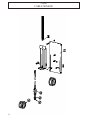
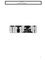
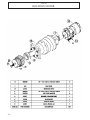
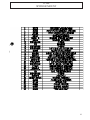
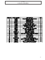
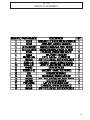
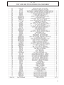
T-WREX
PARTS, DRAWINGS,
SERVICE & OPERATION MANUAL
T-WREX SR. MODEL 60000 TW
S/N: 100 - 105
HAWK INDUSTRIES INC.
1245 EAST 23RD STREET
SIGNAL HILL, CA 90755
USA
PHONE: +1-562-424-0709
FAX: +1-562-490-9959
WWW.HAWKINDUSTRIES.COM
5/13
AIR AND HYDRAULIC REQUIREMENTS
ALL CONFIGURATIONS REQUIRE A HYDRUALIC POWER UNIT CAPABLE
OF DELIVERING 20-35 GPM AT 3000 PSI CLOSED-CENTER
Compressed Air: 100psi @ 10-20cfm for air piloted models
51700
T-WREX SR. ASSEMBLY
4
51700
T-WREX SR. ASSEMBLY
5
51627
MAIN MANIFOLD ASSEMBLY
6
51627
MAIN MANIFOLD ASSEMBLY
7
5250-0528A
SPINNER MANIFOLD ASSEMBLY
8
51625
SUPPLY VALVE ASSEMBLY
9
51482
LOGIC PANEL ASSEMBLY
10
51440
ROTATION LIMIT ASSEMBLY
11
51800
CABLE SENSOR
12
51800
CABLE SENSOR
13
51480
RELAY BOX ASSEMBLY
14
51480
RELAY BOX ASSEMBLY
15
T168
50 FOOT CONNECTOR
16
NOTES:
17
51507
CONSOLE ASSEMBLY
18
51507
CONSOLE ASSEMBLY
19
51141
SYNCHRONIZATION ASSEMBLY
See pages 72-73 for adjustment information.
Previous models utilized a slave cylinder configuration.
See next pages for slave cylinder location, parts, and procedure.
20
51141
SYNCHRONIZATION ASSEMBLY
21
SLAVE CYLINDER CONFIGURATION
22
SLAVE CYLINDER CONFIGURATION
23
SLAVE CYLINDER CONFIGURATION
SLAVE
CYL.
24
SLAVE CYLINDER CONFIGURATION
(1)First the T-WREX should be FULLY extended using the manual control lever on the center section
of the arm, under the cover.
(2)Next, remove the rear cover to expose the lift cylinder and the slave cylinder.
(3)Turn both the HPU and e-stop off. On the extension cylinders, remove the -8 caps on the tee fittings
and connect jumper hoses between left and right cylinders, both in the front and rear sections of the
arm.
(4)Turn HPU back on. Raise the tool high enough that the front section can not hit the floor using the
manual control lever on the center section of the arm.
(5)Again using manual control on the arm, fully extend and retract the tool several times (six to ten).
Leave the tool in the fully extended position and lower it fully.
(6)Turn off the HPU again. Disconnect hoses from lift cylinder, marking them as to which fitting they
connect to.
(7)Using -8 to -6 adapters on the slave cylinder, connect lift hoses to tee fittings on the slave cylinder.
(8)Using manual controls again, actuate the raise and lower valve, repeatedly (6 to10) times, being careful to fully extend and retract the slave cylinder each time, but not holding the control long enough to
cause the arm to begin to retract.
(9)Leave the slave cylinder in the retracted position (opposite the extension cylinders, which should be
fully extended at this point).
(10)Turn the HPU off. Being careful to minimize oil loss and air intrusion, remove jumper hoses one at
a time and cap tee fittings.
(11)Remove lift hoses from slave one at a time and cap, to minimize air intrusion, and then reconnect
lift hoses to the lift cylinder on the appropriate fittings.
(12)Turn HPU and e-stop back on and verify that the extend and retract functions actuate smooth and
level from the control console. Replace top and rear covers.
25
51210
MAIN SUPPORT ASSEMBLY
26
51210
MAIN SUPPORT ASSEMBLY
27
51235
ROTATION MOTOR
28
NOTES:
29
51211
TROLLEY ASSEMBLY
30
51211
TROLLEY ASSEMBLY
31
51212
EXTEND/RETRACT ASSEMBLY
32
51212
EXTEND/RETRACT ASSEMBLY
33
950TW
T-WREX SPINNER
34
950TW
T-WREX SPINNER
35
51160
MOTOR CLAMP ASSEMBLY
36
51160
MOTOR CLAMP ASSEMBLY
37
24625
SPINNER GEARBOX
38
24625
SPINNER GEARBOX
39
51300
SPINNER MOUNT
40
51300
SPINNER MOUNT
41
51701
C-HEAD ASSEMBLY
42
51701
C-HEAD ASSEMBLY
43
51750
WRENCH ASSEMBLY
44
51750
WRENCH ASSEMBLY
45
51114-UPPER
46
51114-LOWER
47
H17-TW
T-WREX SR. TORQUE CYLINDER ASSEMBLY
48
H17-TW
T-WREX SR. TORQUE CYLINDER ASSEMBLY
49
51751
TOP AND BOTTOM WRENCH ASSEMBLY
50
51751
TOP AND BOTTOM WRENCH ASSEMBLY
51
51752
MIDDLE WRENCH ASSEMBLY
52
51752
MIDDLE WRENCH ASSEMBLY
53
50209-TOP
TOP HEEL DIE HOLDER ASSEMBLY
54
50209-MID
MIDDLE HEEL DIE HOLDER ASSEMBLY
55
50209-BOT
BOTTOM HEEL DIE HOLDER ASSEMBLY
56
51711-TB
TOP AND BOTTOM DIE HOLDER ASSEMBLY
57
51711-MID
TO AND BOTTOM DIE HOLDER ASSEMBLY
58
Operation
&
Service Manual
59
General
Safety Requirements
Hawk equipment is installed and operated in a controlled drilling rig environment
involving hazardous situations. Proper maintenance is important for safe and reliable
operation. Procedures outlined in Hawk manuals are the recommended methods of
performing operations and maintenance.
Personnel Training
All personnel performing installation, operations, repair, or maintenance procedures on the
equipment, or those in the vicinity of the equipment, should be trained on the rig safety, tool
operation, and maintenance to ensure their safety.
*Only authorized Hawk repair technicians should perform major disassembly and assembly
procedures.
Recommended Tools
Service operations may require the use of tools designed specifically for the pupose described.
Hawk recommends that only those tools specified be used when stated. Ensure that personnel
and equipment safety are not jeopardized when following service procedures or using tools not
specifically recommended by Hawk.
General Safety Practices
The equipment discussed in this manual may require or contain one or more utilities, such as
electrical, hydraulic, or pneumatic.
*Isolate energy sources before beginning work.
*Avoid performing maintenace or repairs while the equipment is in operation.
*Wear proper protective equipment during equipment installation, maintenance or repair.
Replacing Components
*Verify that all components (such as cables, hoses, etc.) are tagged and labeled during assembly
and disassembly of equipment to ensure correct installation.
*Replace failed or damaged components with Hawk certified parts. Failure to do so could result
in equipment damage or injury to personnel.
60
Description
T-WREX is a pedestal mounted wrench/spinner
combination tool for making up and breaking out
threaded tubulars on drilling rigs.
A fully operational T-WREX consists of the following assemblies:
*Transportation pallet
*Pedestal, complete unit
*Controls, complete with remote console, and control lines to tool
*All documentation
OPTIONAL:
*Floor socket/recieving tube (PN 51201), cut to 16” in length.
61
Installation
62
Lifting the T-WREX
Before lifting the T-Wrex, verify that the trolley is in the full down position and the extending
arms are fully retracted. Use the four lifting shackles attached to lugs on top of the C-Head and
Trolley with lifting sling assembly (Sr. sling PN 51702, Jr. sling PN 51202).
*Always use the lifting lugs and shackles provided. Nothing else is rated for, nor intended to
support the full weight of the T-Wrex.
63
Transporting the T-WREX
Whenever transporting the T-Wrex, make sure the unit is supported in a stable manner. Attach
tie-down straps to the four provided lifting shackles attached to the lugs of the C-Head and
Trolley to the transportation pallet (pallet PN 51550) lugs.
64
51886 Control System Elements
The T-WREX controls are face mounted on a remotely located console.
Each lever/button introduces compressed air into different sections of the pneumatic control
system.
A misrouted air line can cause the tool to operate in a manner not intended by the operator.
There are air operated elements in the control system that will route, close off, or vent air signals
to pilot the hydraulic valves.
These elements are located under the control console panel, in the relay box, and up on top of
the extending center pivot -- under a large box-shaped cover (four bolts).
There are two basic logic element types in T-WREX’s control system, with the more
complicated circuits being of varying configurations of logic elements combined.
The ‘OR’ element (PN L15): it has two inputs and one output. Described easily: a three port “Y”
with no crosstalk between the two input ports. Crosstalk is the energizing of an input port from
another input port.
The other element is the air piloted valve (PN A501, or PN A508).
It has one pilot (spring return) or two pilot ports (pilot return), one air supply port, two output
ports, and two venting exhaust ports.
These valves have an internal spool shifted by at least one pilot signal (compressed air).
The input (supply air) is routed by the position of the internal spool to one output port only.
The input port on this valve is located between the two exhaust ports. The two output ports are
on opposite face.
The other pneumatic elements whithin the control system are relays, logical NOT, and
mechanical input valves (rotation and extend limits, set by operator).
65
51200/51700 General Arrangement
66
51507 Control Console
EMERGENCY STOP (detented): De-energize pneumatic control system
MAKE/BREAK MODE (selector): Toggle tool operation
Operator must properly align the two working wrenches to box/pin shoulder line with the
HEIGHT control lever.
On make: align between bottom and middle wrenches
On break: align between top and middle wrenches
ROTATE (lever): Rotate entire unit about pedestal
ROTATE (button): Bypass rotate sensors when rotating, OR speed up unit when retracting
EXTEND (lever): Extend wrench and spinner units to target
FINAL ADJUST (momentary):
Jog unit in extend (forward), short distance (pneumatic timer)
Used to obtain correct bite. Also used to bypass extend stops when extending.
HEIGHT (lever): Align wrenches to target for proper operation. Trolley lift/lower.
TILT (lever): Align spinner and wrench head parallel to drill string.
GRIP (detented, wrench nuts must be set to target size): Grip target with back-up wrench
SPIN (momentary, spinner must be set to target size with SPINNER ADJUST):
Spin in new connection, or spin out an untorqued connection.
CHAIN OILER (momentary): Lubricate spinner chain, only during spinning operation
TORQUE (momentary): Grip target with torqing wrench and extend torque cylinder
SPINNER ADJUST (selector)
UNCLAMP: Unclamp motor assembly from spinner case, air cylinder pulls motor forward
ADJUST: Air cylinder pushes spinner motor back putting tension on chain
CLAMP: Clamps motor assembly to spinner case, must be clamped for spinning operation
TORQUE ADJUST (knob, pilot valve): Adjust wrench output torque. To be set after initial
spin and torque. Final reading read at begining of torque cylinder stroke while torqing. Rotate
adjustment knob in for more torque, out for less.
TORQUE GAUGE (torque arm calibrated gage): Torque indicator, displayed in FT/LBS.
Read at begining of torque cylinder stroke while torquing.
67
51141 SYNCRONIZATION ASSEMBLY ADJUSTMENT
T-WREX’s reach assembly consists of front and rear arms that require syncronization.
To achieve syncronization front to rear, front and rear hydraulic cylinders must receive an equal
volume of hydraulic oil. 51141 is a continously correcting mechanical-input hdyraulic flow divider.
adjust hex
locking bolt
T170
(1)Extend unit fully.
(2)Loosen locking bolt, then tighten snug.
(3)Use 1 1/8” wrench to adjust T170 to starting point on cam.
(4)Tighten locking bolt enough to keep driving gear from rotating
during extend/retract operation.
(5)Retract unit 3-4 feet.
(6)Extend unit fully while observing which arm extends last.
68
(3)starting point
51141 SYNCRONIZATION ASSEMBLY ADJUSTMENT
Either back or front arms will extend last. Rotate adjust hex clockwise or counterclockwise accordingly.
rear arm extends before front arm,
adjust hex counter clockwise to increase flow
to front/reduce to rear.
front arm extends fully before rear arm,
adjust hex clockwise to increase flow to rear/reduce
to front.
Repeat setps 5 and 6 after each adjustment.
The closer the arms get to syncronization, micro adjustments are required.
Tighten lockbolt and tap adjusting wrench with deadblow hammer to make small adjustments.
Adjustment is complete when both front and back arms extend fully at the same time.
69
Setup Wrenches
To set wrenches:
Scale on wrench refers to target O.D.
Scale is read looking straight down, reading graduation just outside the nut.
Check die retaining plate pointers after griping for correct indication, extend/final
adjust/retract/tilt as neccessary.
Align wrenches and
spinner parallel to pipe
with TILT
70
Extend until
heel side die holder bolt head
is centered over pipe
Setup Wrenches
Once lined up,
hit the grip button and take a reading
A good bite,
pointer on die holder retainer plate
lines up with bolt head
Under-bite condition, un-grip,
check wrench nuts, rotate nut out for more bite
OR if heel side is NOT lined up to pipe center
use FINAL ADJUST button (momentary)
Over-bite condition, un-grip,
check wrench nuts, rotate nut in for less bite
OR if heel side is not lined up to pipe center
use RETRACT LEVER,
then FINAL ADJUST button (momentary)
71
51200/51700 Setup Limits
Extend Limits
Two adjustable extend limits disable EXTEND function when one is triggered.
These are set to well and mouse hole centers. Pressing the FINAL ADJUST button while
extending will bypass these limits.
Rotate Limits
Two adjustable rotation limits disable ROTATE function when one is triggered.
These are set to well and mouse hole centers. Pressing the ROTATE button while rotating will
bypass these limits.
72
950TWA Spinner Adjust
WRENCHES MUST BE SET PRIOR TO SPIN OPERATION
To adjust spinner:
1.) Retract unit off target. 2.) Place SPINNER ADJUST to UNCLAMP
3.) Extend unit until target is nested into spinner.
a.) Place SPINNER ADJUST to ADJUST
b.) Place SPINNER ADJUST to CLAMP
SPINNER IS NOW SET
4.) GRIP and SPIN
4
1
2
3a
3b
73
Operating Modes
T-WREX utilizes a three wrench system for making up and breaking out threaded tubulars. Only
two of the three wrenches will operate in either make or break mode.
Make: This mode sets the tool to make up new connections.
In this mode, the bottom wrench backs up the middle torquing wrench. Enabling the grip
button (detented) in this mode will grip bottom as back-up wrench. Pushing the torque button
(momentary) will sequence middle wrench grip and torque operation.
Break: This mode sets the tool to break out made connections.
In this mode, the middle wrench backs up the top torquing wrench. Enabling the grip
button(detented) in this mode will grip middle as back-up wrench. Pushing the torque
button(momentary) will sequence top wrench grip and torque operation.
Break
Make
Required wrench position relative to tool joint line for make or break mode.
74
Control Sequence
Basic Operation:
1. Set wrenches (pages 75-76)
2. Set spinner (page 78)
3. Set a rotate and an extend limit (page 77)
4. Height adjust for make or break (refer to previous page)
5. Hit GRIP
6.
For Make:
hit SPIN until shouldered, release
hit TORQUE until torqued, release
UN-GRIP
For Break:
hit TORQUE until joint is broken, release
hit SPIN until done, release
UN-GRIP
7. Retract unit off target, continue drilling operation
75
Routine Maintenance
Maintain:
Wrenches:
Grease wrench nut threads
Check dies for wear, replace if slipping
Spinner:
Check chain for wear
Hit OILER button for 3-5 seconds every third or fourth spin
Grease:
Zerk fittings in and around:
Spinner
Wrench head
Main rotation bearing assembly (PN 51220)
Check:
Hydraulic oil level in power unit (PN 51640)
Air filter indicator, replace filter if indicator is red
Hydrualic oil filter indicator, replace filter if indicator is red
Equipment must be maintained on a routine basis.
*Failure to conduct routine maintenance could result in equipment damage or injury to
personnel.
Proper Use of Equipment
Hawk equipment is designed for specific functions and applications, and should be used only for
its intended purpose.
76
Die Holder Wear
77
Consumers Data
78
MAINTENANCE
SCHEDULES
79