1
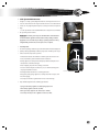
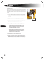
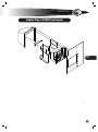
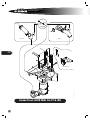
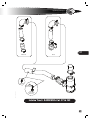
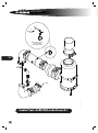
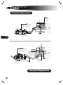
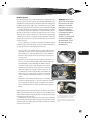
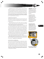
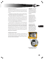
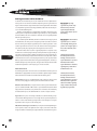
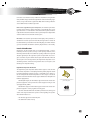
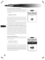
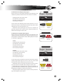
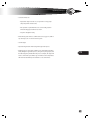
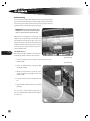
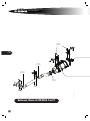
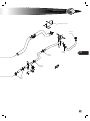
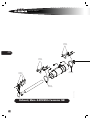
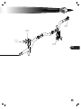
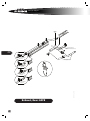
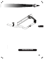
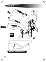
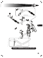
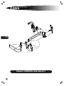
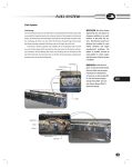
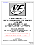
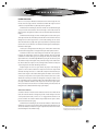
I n ta k e & E x h au s t
Intake Overview
Clean air is necessary for efficient fuel combustion and for normal engine life. If allowed to enter the engine, airborne contaminants combine with engine oil to form
an abrasive compound which may drastically shorten engine life.
On All American Forward Engine, the fresh air intake is located behind the right
access panel on the front of the bus. Air enters through a screened duct into the air
filter, mounted to the right of the radiator, and accessible from underneath the front
bumper.
On All American Rear Engine, the fresh air intake grille is located at the top rear
of the right side of the bus, immediately rearward of the rearmost window. Air enters
through leuvers in the body panel into a screened duct leading to the air cleaner,
with is mounted in the top right of the engine compartment. An optional precleaner
(Feature 40170-01) is installed on some All American Rear Engines, immediately behind fresh air intake grille.
Fresh air passes through ductwork leading to the air filter, where airborne dirt,
dust and other foreign particles are trapped in the replaceable dry filter element.
Air from the air filter enters a duct leading to the intake side of the engine’s turbocharger. The turbocharger contains two turbine chambers which are internally
sealed from each other. Exhaust gas passes through the exhaust-side chamber, driving the turbine vanes and shaft at high RPM before passing into the exhaust system.
The turbine shaft passes through the body of the tubo charger to the intake chamber, where it drives the compressor vanes, drawing intake air from the air filter, and
compressing into the inlet tube of the Charge Air Cooler.
Compressing the air causes it to give off heat. The purpose of the Charge Air
System is to remove this heat before the compressed air enters the engine intake
manifold. The Charge Air Cooler is a radiator-like component mounted directly to
the front of the engine coolant radiator. Although the two radiators are mounted as
a unit, they are components of two separate circuits and do not share air or coolant.
Ambient air is drawn by the radiator fan through the cooling fins of both coolers.
The cooled intake air proceeds from the CAC to the intake manifold, where it enters
the engine combustion chambers under compression. This increases engine performance, and reduces emissions due to more efficent burning of the diesel fuel. The
Charge Air Cooler is illustrated in the Cooling System chapter.
Air Restriction Indicator
A restriction indicator is mounted in the intake tract between the air filter and the
turbo. The restriction indicator is designed to provide a visual warning in the event
of overly restricted air intake, as in the case of a clogged air filter element or the
presence of debris. The restriction indicator may be fitted with an option to drive a
dash-mounted air restriction gauge.
On All American Forward Engine, the air restriction indicator is visible inside the
right front access panel, next to the fresh air inlet. On Rear Engine All Americans, the
air restriction indicator is visible in the engine compartment, mounted on the side of
the duct leading from the air filter housing.
695
Air Restriction Indicator, Forward Engine
Air Restriction Indicator, Rear Engine
At a vaccuum of 25 inches H20, the red piston locks,
indicating that the air intake tract is too restricted.
L
service manual
During engine operation, the indicator monitors vaccuum pressure immediately downstream of the air filter. As vaccuum increases, the indicator’s red piston
becomes visible through the clear portion of the housing indicating that air flow is
being restricted by a clogged filter, debris, or other obstruction. The Air Restriction
Indicator is variable until the monitored vaccuum increases to a measure of 25 inches
H2O. At that measure, the red piston fills the clear portion, and locks in its position.
The indicator must then be manually reset by pressing the reset button after the
restrictive condition has been corrected.
[CAUTION] The Air Restriction Indicator activates only when an air flow
restriction has occured. A normal reading (no red showing) must not be misunderstood as an indication that the air filter is clean, and does not preclude
the need for other inspection and maintenance. For example, a leak in the
intake will allow damaging debris to enter, but will not be indicated by the Air
Restriction Indicator.
696
L
Filter restriction and proper operation of the indicator may be verified by pressing
the reset button on the bottom of the indicator. If restriction is occurring, the red
indictor will move when the engine is under load. The indicator will lock in position if
the monitored vaccuum increases to 25 inches H2O.
It is important to understand that the Air Restriction Indicator does not detect
leaks, and will not properly indicate restrictions in a leaking system. Check for leaks in
all inlet hoses, tubes and connections. If a leak is found, correct it immediately, using
original replacement parts and torqing all clamps.
The Air Restriction Indicator can also be tested using a calibrated vacuum gauge
and vacuum pump. Check the full range of the indicator, and verify that the red indicator locks into position at 25 inches H2O. The Air Restriction Indicator is not repairable, and should be replaced if found to be operating incorrectly.
intake
&
exhaust
Intake System Maintenance
Although it is a simple system, dilligent maintenance and inspection of the air intake tract is critical. Never run the engine with the air cleaner or its filter element
removed. Use only original replacement parts to avoid poor fit and consequent air
leakage.
See the Specifications and Scheduled Maintenance chapter for recommended
intake system inspection intervals.
[CAUTION] The intake system inspection and maintenance intervals indicated in this manual are guidelines which assume normal operating conditions.
Appropriate service intervals vary according to operating conditions. In dusty
or high humidity environments, more frequent service is required.
A3FE Air Filter elbow clamp
General Inspection
Under normal operating conditions, inspect the Air Restriction Indicator daily (more
frequently in dusty high humidity conditions). Inspect the air intake system every 3
months or 5000 miles. Inspect the system for:
• Air Restriction Indicator. If red indicator is visible, replace the air cleaner element, and check the system for debris and other restrictions.
• Clamps. Tighten loose clamps and check for proper fit and seal. Replace if corroded, broken or otherwise damaged.
• Ducts and piping. Inspect for wear, damage, or abrasion.
• Air cleaner element. Replace if soiled, wet, torn, or otherwise damaged. Ensure proper installation and seal.
• Mounting brackets. Check for loose or damaged mounts.
• Charged air system piping. Tighten loose clamps. Check for wear spots and
holes in the piping.
• Air compressor inlet lines. Tighten. Check for wear or other damage.
697
A3FE Air Filter mounting clamps
Clamps should be tightened to the following specifications:
Spring-loaded clamps. Tighten to near full spring compression.
T-Bolt clamps. Tighten to 50 in. lbs. (5.6 Nm).
Worm gear clamps. Tighten to 38–42 in. lbs. (4.2–4.7 Nm).
Hose clamps already in service. Tighten to 10 in. lbs. (1.1 Nm).
L
service manual
Air Filter Replacement
Replace the air filter element at least once a year, and whenever the Air Restriction
Indicator has been activated (shows red). Other indicators of a dirty air cleaner element include loss of power or excessive exhaust smoke. To replace the air cleaner
element:
1. Loosen the spring clamp which secures the intake elbow (FE) or intake hump
hose (RE) to the air filter canister. Push the intake elbow or hump off of the
filter flange.
2. Release the clasps of the two mounting clamps and remove the filter.
3. On Rear Engine All-American, remove the clamp and intake tube from the
top of the filter. Clean the tube and install it on the new filter.
4. Before replacing the element, inspect all clamps, hoses, piping and seals:
698
• Inspect inside the intake elbow or hump hose for signs of dust or debris finding its way into the system through leaks. Replace any damaged components allowing the leak, and clean the debris inside the
elbow and ducts before installing a new element.
• If evidence of leaks is found, check the tube between the charged air
cooler and the engine intake for contamination. If contamination is
found, the charged air cooler should be replaced.
5. Install a new air cleaner element, fully seating its top seal.
6. Assemble removed parts in reverse order of disassembly. Ensure that the intake elbow or hump hose is properly seated all the way around the flange of
the filter. All duct connections downstream of the air filter must be air tight.
L
A3RE Air Filter Hump Hose clamp
A3RE Air Filter mounting clamp
intake
&
exhaust
Intake Tract: A3RE Precleaner
0052694c
699
L
service manual
W/ 40280-11
To Turbo
To Dash Mtd
Restr. Gauge
To Front Mtd
Restr.indicator
To Turbo
CAT C7-07
ISB-07
700
0108398d
FEATURE 40113-03
Intake Tract: A3FE With Cat C7 & ISB
L
intake
CAT C7-07
&
exhaust
ISC-07
701
STANDARD
0111836a
TO DASH MTD.
RESTRICT. GAUGE
DASH MTD.
RESTRICT. GAUGE
FEAT.40280-11
Intake Tract: A3RE With Cat C7 & ISC
L
service manual
To
Dash Mounted
Gauge
With Feature 40280-11
Dash Mounted
Air Restriction Gauge
702
To CCV
Filter Inlet
0041893H
To Turbo
Intake Tract: A3RE With John Deere 8.1
L
intake
&
exhaust
703
L
service manual
Cummins Regeneration
2
Fuel Injectors
In Regeneration mode,
a small amount
of fuel is injected during
exhaust stroke.
Exhaust
Drives
Turbo
1
Particulate Filter Sensors
Compare exhaust condition before and after
particulate filter element.
When potential clogging is detected, ECU
initiates Regeneration mode.
Exhaust
Stroke
3
The extra fuel
enters the exhaust stream…
4
…and contacts Catylitic Converter,
generating heat to incinerate accumulated
deposits in Particulate Filter.
704
Fresh Intake From
From Air Filter
To
Charge Air
Cooler
1
Fuel
Air
Particulate Filter Sensors
Compare exhaust condition before and after
particulate filter element.
When potential clogging is detected, ECU
initiates Regeneration mode.
2
Aftertreatment
Regeneration Device
During Regeneration,
ignites its own fuel and air supply,
raising exhaust temperature to
incinerate Particulate Filter
accumulation.
CGI Cooler
3
The heightened exhaust
temperature burns away
accumulated residue from
Particulate Filter.
Clean Gas Induction
Partial exhaust is redirected back toward engine.
Recirculated exhaust is cooled
and re-introduced to compression
side of turbo.
CGI Valve
Regulates amount of
recirculated exhaust
entering Turbo.
Caterpillar Regeneration
L
intake
&
exhaust
Exhaust System
New federally mandated emission standards affect all buses equipped with 2007 or
newer diesel engines. The exhaust systems of both Caterpillar and Cummins engines
in Blue Bird buses are aftertreatment systems which incorporate Diesel Particulate Filters (DPF) instead of ordinary mufflers. These sophisticated exhaust systems reduce
emissions by trapping exhaust-borne particulates (soot) in a filter built into the DPF.
Over time, the trapped soot accumulates in the DPF, and must be removed by a
process referred to as regeneration. Regeneration is conceptually similar to the cleaning mode of a self-cleaning oven in that heat is required to remove the soot. Regeneration converts most of the accumulated soot to carbon dioxide, and leaves behind
a small amount of ash. Because of the higher operating temperatures involved, the
exhaust system components are now more insulated from other chassis components
than in previous years.
The rate at which the soot accumulates is dependent upon multiple conditions
including the quality of the diesel fuel, type of engine oil, ambient temperature, engine load, and other factors. Regeneration occurs in three ways:
[Caution] In 2007 diesel engines, use only diesel fuel labeled
Ultra Low Sulfer, per the engine
manufacturer’s specifications.
In Caterpillar, use oils meeting
API CJ-4 or Caterpillar ECF-3
compliant. See Caterpillar Operation and Maintenance Manual
SEBU8083-08 for details.
In Cummins, use oils meeting API
CJ-4/SL and Cummins Engine
Standard CES-20081. See Cummins Owners Manual ISB 6.7L
CM2150 for details.
• Some regeneration occurs “naturally” whenever operating conditions (speed,
engine load, etc.) result in exhaust system temperatures high enough to oxidize accumulated soot. Terminology differs between engine manufacturers,
but this unassisted regeneration mode can generically be referred to as “passive” regeneration.
• Regeneration can be caused by raising the temperature of the exhaust system. A set of sensors mounted on the DPF assembly enable the Engine Control Module (ECM) to monitor the buildup. The ECM then automatically activates and de-activates a system designed to increase exhaust
temperature when the ECM senses that regeneration is needed, and
when certain requirements, including a minimum travel speed, are
met. Although the specific mechanisms differ, both Caterpillar and
Cummins engines are equipped with such systems. This automatic
“heat assisted” mode can be generically referred to as “active” regeneration.
• Regeneration can be manually activated by means of a switch. This
procedure is generically referred to as “stationary” regeneration, and should
only be performed by or under the direction of a qualified service technician,
and in a controlled environment to avoid the potential for human injury or fire
hazards.
The ECM communicates the need for regeneration to the driver by a set of visual and
audible signals in the instrument panel. An additional alert, the High Exhaust System
Temperature (HEST) indicator, notifies the driver whenever exhaust system temperature is high due to recent regeneration.
Periodically, the normal ash accumulation which results from the regeneration
process must be removed from the DPF, using equipment designed for the purpose
at qualified engine service facilities. Refer to the engine manufacturer’s documentation for these service intervals.
705
The exhaust systems of 2007 and newer engines incorporate
engine-specific Diesel Particulate Filters, which operate
at higher temperatures during their Regeneration cycles.
The front exhaust pipes are insulated, and heat shields are
installed at locations along the exhaust tubing. (Caterpillar
shown.)
L
service manual
Engine-Specific Technologies
Although the purpose and general principles of aftertreatment exhaust systems are
similar, both the terminology and the mechanisms to perform “active” regeneration
differ among engine manufacturers.
Caterpillar and Cummins have also each developed their own technologies for
accomplishing and controlling the active regeneration process. The engine-specific
ECMs which control the process are different. Differences also exist between engine
manufacturers in the construction of the DPF units, the exhaust flow paths, and other related components. It is for these reasons that the service technician must now
regard that portion of the exhaust system from the engine to the outlet port of the
DPF as part of the engine package itself.
This chapter provides separate conceptual explanations of the Caterpillar and
Cummins systems. However, the service technician must refer to the engine manufacturer’s operators’ manual and service literature regarding service and maintenance of
the 2007 and newer exhaust systems.
Regeneration Process In Caterpillar Engines
706
2007 emissions standards-compliant Caterpillar engines incorporate the Caterpillar
Regeneration System (CRS). Exhaust leaving the turbo flows through an Aftertreatment Regeneration Device (ARD) mounted on the right side of the engine. The ARD is
a chamber equipped with its own fuel injector, air intake, and spark plug.
Caterpillar Passive Regeneration
As the engine runs, exhaust merely passes through the ARD on its way to the exhaust
pipe and into the DPF. If the engine’s duty cycle generates sufficient heat, some of the
soot accumulation is removed, even though the ARD is not activated. This unassisted
regeneration mode is called Passive Regeneration.
At moderate and continuous speeds or engine load conditions, normal exhaust
temperatures may be maintained at a high enough level for Passive Regeneration to
“hold its own” against additional accumulation. Under frequent or prolonged moderate-to-heavy operating conditions, Passive Regeneration may even “gain ground”
against the accumulation.
Caterpillar Active Regeneration
Accumulation occurs most at low speeds and relatively low temperatures. Frequent
stop-and-go and continual low-speed operation typical of some school bus routes
may not generate sufficient heat for Passive Regeneration to keep the DPF clear.
Sensors monitor the pressure differential before and after the DPF, and also
monitor temperature. The pressure and temperature data is communicated to the
ECM. When the readings indicate that the particulate filter is beginning to become
restricted, the ECM may signal the system to enter Active Regeneration mode.
During Active Regeneration, a small amount of fuel and air is injected into the
ARD, and is ignited by its spark plug. This combustion within the ARD raises the temperature of the exhaust flow sufficiently to remove the residue downstream in the
DPF. This process occurs automatically and as-needed during normal operation.
L
intake
Active Regeneration only occurs if DPF accumulation has reached a certain level,
and if the bus is moving above a preset speed threshold (20 mph). If the bus is operated long enough (typically 20-30 minutes) at a speed above the Active Regeneration speed threshold, the accumulation clears and Active Regeneration mode stops.
If the bus is slowed to below a certain speed threshold while in Active Regeneration
mode, the Active Regeneration stops, even if the cleaning process has not completed. If the bus slows or stops while the exhaust system temperature is still high due
to recent Active Regeneration, the HEST indicator appears on the driver’s instrument
panel to notify the driver that the system is hot.
Caterpillar Stationary Regeneration
Active Regeneration removes the accumulation at an increased rate. However, each
time the bus slows to below the Active threshold, and each time exhaust temperature drops below that at which Passive Regeneration occurs, accumulation has opportunity to increase.
Therefore, depending upon the operating conditions, there may not be sufficient
opportunity or duration for either Passive or Active Regeneration to keep the filter
clear, and a Stationary Regeneration must eventually be performed.
During Stationary Regeneration, temperatures inside the exhaust can exceed
1200°F. Stationary Regeneration must be performed only in a controlled environment where all reasonable precautions are taken to avoid any hazard that might result from the elevated temperatures. Blue Bird strongly recommends that Stationary
Regeneration be performed only by, or under the supervision of, a qualified service
technician. Read carefully the section titled Stationary Regeneration Precautions.
Stationary Regeneration is initiated by means of a momentary toggle switch.
Operating the switch starts a Stationary Regeneration only if certain conditions are
true: The ECM must have indicated that regeneration is needed (as indicated by the
appearance of the DPF indicator); the bus must be stopped with parking brake on;
the engine must be running; and the transmission must be in Neutral.
During a Stationary Regeneration procedure, the process is monitored and controlled by the ECM and CRS. The Stationary Regeneration process continues until the
filter is clean, and then stops. The bus may then be returned to normal service. (For
more information, see DPF Regeneration In Blue Bird Buses.)
Clean Gas Induction in Caterpillar Engines
The exhaust system of the Caterpillar C7 engine also utilizes Clean Gas Induction
(CGI). A portion of the exhaust is “recycled” through the engine to help control emissions. Just before the DPF outlet, a portion of the exhaust gases is re-directed back
toward the engine through a 2 1/2” tube. This inert exhaust enters a CGI Cooler, located
on the right side of the engine, below the turbo and forward of the ARD. Enveloped
in the engine coolant circuit, the CGI Cooler lowers the temperature of the incoming
exhaust. The cooled exhaust flow then re-enters the compressor side of the turbocharger through an electrically-controlled, hydraulically-actuated mixing valve, and
is re-introduced into the intake flow.
&
exhaust
[WARNING] The aftertreatment
regeneration process can cause
extremely high exhaust gas temperatures hot enough to ignite or
melt common materials, and to
burn people.
Carefully read, understand,
and abide by all instructions,
warnings, and cautions in the
engine manufacturer’s operator’s
manual (and other related
engine manufacturer’s literature)
regarding safe operation when
the HEST indicator is on.
Carefully read, understand,
and abide by all instructions,
warnings, and cautions in the
engine manufacturer’s operator’s
manual (and other engine manufacturer’s literature) regarding
safety conditions when performing Stationary regeneration.
707
Regeneration switch for use by Service Technicians
performing Stationary Regeneration only in a
controlled, fire-hazard-free environment.
L
service manual
Regeneration Process In Cummins Engines
2007 emissions standards-compliant Cummins engines incorporate the Cummins Aftertreatment System. When elevation of exhaust temperature is needed to facilitate
regeneration, this system utilizes the engine’s fuel injectors to inject a small measure
of fuel during the exhaust strokes of the engine’s cycle.
Cummins Passive Regeneration
When driving at high speeds or with heavy loads, the exhaust system is hot enough
to turn soot accumulation inside the DPF into carbon dioxide. Temperatures generated in this mode are comparable to those of pre-2007-standards engines.
At moderate and continuous speeds or engine load conditions, normal exhaust
temperatures may be maintained at a high enough level for normal operation to
“hold its own” against additional accumulation. At moderate-to-heavy operating
conditions, normal exhaust heat may even “gain ground” against the accumulation.
708
L
Cummins Active Regeneration
Accumulation occurs most at low speeds and relatively low temperatures. Frequent
stop-and-go and continually low-speed operation typical of some school bus routes
may not always generate sufficient heat for normal running to keep the particulate
filter clear.
Sensors monitor the pressure differential before and after the DPF, and also
monitor temperature. The pressure and temperature data is communicated to the
ECM. When the pressure / temperature readings indicate that the particulate filter
is beginning to become restricted, the ECM may signal the system to enter Active
Regeneration mode.
During Active Regeneration, a small amount of fuel is injected into the exhaust
stream by the engine’s fuel injectors during the engine’s exhaust stroke. This fuel reacts with the catalytic converter in the DPF, raising the temperature of the exhaust
flow sufficiently to remove the residue. This process activates and deactivates automatically and as-needed during normal operation.
Active Regeneration begins only if DPF accumulation has reached a certain level,
and if the bus is moving above a preset speed threshold (approximately 40 mph). If
the bus is operated above the speed threshold long enough, the accumulation clears
and Active Regeneration mode stops.
If the bus is slowed to below a certain speed threshold while in Active Regeneration mode, the Active Regeneration stops, even if the cleaning process has not
completed. If the bus slows or stops while the exhaust system temperature is still
high due to recent Active Regeneration, the HEST indicator appears on the driver’s
instrument panel to notify the driver that the system is hot.
intake
Cummins Stationary Regeneration
Active Regeneration removes the accumulation at an increased rate. However, each
time the bus slows to below the cut-off threshold, and each time exhaust temperature drops to levels insufficient for soot to be cleared, accumulation has opportunity
to increase.
Depending upon the operating conditions, there may not be sufficient opportunity or duration for either normal running or Active Regeneration to keep the filter
clear, and a Stationary Regeneration must eventually be performed.
During Stationary Regeneration, temperatures inside the exhaust can exceed
1300°F. Stationary Regeneration must be performed in a controlled environment
where precautions are taken to avoid any hazard that might result from the elevated
temperatures. Blue Bird strongly recommends that Stationary Regeneration be performed only by, or under the supervision of, a qualified service technician. Read carefully the section titled Stationary Regeneration Precautions.
Stationary Regeneration is initiated by means of a momentary toggle switch.
Operating the switch starts a Stationary Regeneration only if certain conditions
are true: The ECM must have indicated that Regeneration is needed (as indicated
by appearance of the DPF indicator); the bus must be stopped with parking brake
on; the engine must be running; and the transmission must be in Neutral. During a
Stationary Regeneration procedure, the process is monitored and controlled by the
ECM. Depending upon the severity of the restriction, the engine may or may not raise
its idle speed. The Regeneration process continues until the filter is clean, and then
stops. The bus may then be returned to normal service. (For more information, see
DPF Regeneration In Blue Bird Buses.)
&
exhaust
[WARNING] The aftertreatment
regeneration process can cause
extremely high exhaust gas temperatures hot enough to ignite or
melt common materials, and to
burn people.
Carefully read, understand,
and abide by all instructions,
warnings, and cautions in the
engine manufacturer’s operator’s
manual (and other related
engine manufacturer’s literature)
regarding safe operation when
the HEST indicator is on.
Carefully read, understand,
and abide by all instructions,
warnings, and cautions in the
engine manufacturer’s operator’s
manual (and other engine manufacturer’s literature) regarding
safety conditions when performing Stationary regeneration.
709
Cummins Exhaust Gas Recirculation
In the Cummins ISB engine, a portion of the exhaust is “recycled” through the engine to help control emissions. A device on the engine exhaust system routes a small
amount of the exhaust stream through a cooler, mixes it with fresh air, and re-introduces it into the intake stream. This helps lower the temperature during combustion,
which reduces the formation of Nitrous Oxides.
Regeneration switch for use by Service Technicians
performing Stationary Regeneration only in a
controlled, fire-hazard-free environment.
L
service manual
DPF Regeneration In Blue Bird Buses
710
As with most new mechanical processes, the introduction of more sophisticated exhaust systems in 2007 emission standards-compliant engines has generated some
degree of initial confusion. Engine manufacturers have designed their own methods
to accomplish the regeneration (cleaning) of the DPF, and therefore describe the process in somewhat differing terms.
Whether your Blue Bird bus is equipped with a Caterpillar or Cummins engine,
neither system is complicated. Nor should the regeneration process be regarded with
alarm. Both Drivers and service technicians should be at least conceptually familiar
with the regeneration process.
As soot builds up in the DPF filter, the driver is notified in several stages by visual
and audible alerts. The alert system is designed to provide reasonable and comfortable fore-warning and adequate opportunity for the needed regeneration. As the
need for regeneration becomes more severe, the alerts become increasingly imperative; and the penalty for postponing the needed regeneration also increases.
When the earliest alerts occur, there is typically ample time to complete a route
and then have a Stationary Regeneration procedure performed at a proper facility. If
early alerts are ignored, and the condition is allowed to worsen, the engine will eventually de-rate automatically, and performance will reduce noticeably. If the condition
is allowed to become severe, a Stationary Regeneration may not be possible, and the
DPF may require removal and treatment using specialized equipment. Therefore, to
minimize disruption of your bus operation, the regeneration-related alerts should be
heeded and responded to at their early stages as a matter of routine.
Aftertreatment Terms
The following summarizes some of the terms associated with the exhaust systems of
Blue Bird buses equipped with 2007 emission standards compliant engines. Both the
driver and technician should become familiar with the following terms:
Aftertreatment. The process of highly filtering engine exhaust in order to reduce
emissions, and of purging the exhaust system of accumulated exhaust residue.
DPF (Diesel Particulate Filter). A component in the exhaust system which takes the
place of a traditional muffler. A DPF contains a special dissimilar metals filter which
traps particulate accumulation (soot), which is then converted to carbon dioxide by
the aftertreatment process. The Cummins DPF also contains a catalytic converter.
Regeneration. The process of cleaning accumulated soot from the filtering components inside the DPF. Regeneration occurs at high exhaust system temperatures to
turn the soot into carbon dioxide gas. Regeneration can be thought of as conceptually similar to the clean cycle of a self-cleaning oven.
ARD (Aftertreatment Regeneration Device). A component of the Caterpillar Regeneration System, located on the right side of the engine, at the outlet of the turbocharger. The ARD is controlled by the engine’s ECM and is activated when regenera-
L
[WARNING] Postponing
regeneration beyond the early
indications may result in the
engine being automatically
de-rated, and reduction of power
while driving.
[WARNING] The aftertreatment
regeneration process can cause
extremely high exhaust gas temperatures hot enough to ignite or
melt common materials, and to
burn people.
Carefully read, understand,
and abide by all instructions,
warnings, and cautions in the
engine manufacturer’s operator’s
manual (and other related
engine manufacturer’s literature)
regarding safe operation when
the HEST indicator is on.
Carefully read, understand,
and abide by all instructions,
warnings, and cautions in the
engine manufacturer’s operator’s
manual (and other engine manufacturer’s literature) regarding
safety conditions when performing Stationary regeneration.
intake
&
exhaust
tion needs to occur and the necessary conditions are met. When not in regeneration
mode, the ARD is simply a chamber through which the exhaust flows. During regeneration, a charge of fuel and air is ignited in the ARD, and the resulting combustion
creates additional heat to facilitate regeneration.
HEST Indicator (High Exhaust System Temperature). An instrument panel indicator which appears when the exhaust temperature is unusually high due to recent
regeneration. This is a normal behavior of the aftertreatment system, intended to
notify the driver and technician that the exhaust system temperature is high and that
caution should be observed around the exhaust system.
DPF Indicator. An instrument panel indicator which displays when particulate accumulation has reached a preset level in the DPF, and regeneration is needed. The
bus should either be operated with a more demanding duty cycle until the indicator
goes off, or it should be scheduled for a Stationary Regeneration at a service facility.
Levels of Notification
Regeneration—the process which clears soot accumulation in the DPF—occurs automatically as the bus is operated, as long as certain operating conditions (such as
minimum speed thresholds) are met. When bus operating conditions do not provide
adequate opportunity for the regeneration system to keep the DPF clear, soot begins to accumulate. A system of driver alerts keeps the driver informed of when the
exhaust system is in need of regeneration, and of high exhaust temperature associated with regeneration. Several levels of regeneration alerts occur in sequence, each
indicating a more imperative warning.
High Exhaust Temperature Notification
The High Exhaust System Temperature (HEST) indicator appears to alert the driver
when exhaust temperature is unusually high and that prudent judgement should
be applied regarding the proximity of people or combustibles to the exhaust system. For example, the bus should not be parked on a surface of grass or weeds. The
conditions under which the HEST indicator appears differ between Caterpillar- and
Cummins-equipped buses:
With Caterpillar engine, the HEST indicator appears whenever the exhaust temperature is high (842°F or above), and the bus is either stopped or moving at a slow
speed (approximately 5 MPH).
With Cummins engine, the HEST indicator appears whenever the exhaust temperature is high (752°F or above), regardless of moving speed.
The driver should be familiar with and abide by all instructions, warnings, and
cautions in the engine manufacturer’s operator’s manual regarding safe operation
when the HEST indicator is on.
711
HEST Notification
The HEST alert appears in the instrument
panel’s warning bank.
The audible alert
sounds one beep.
• The HEST alert appears in the instrument panel.
• The audible alarm sounds one beep.
L
service manual
Level 1 Regeneration Notification: DPF Indicator Appears
In low-demand operating conditions, it is possible that the regeneration system does
not have sufficient opportunity to prevent particulate build-up in the DPF. The ECM
senses that accumulation is occurring and that regeneration is needed. The driver is
notified as follows:
• The DPF Regeneration alert activates.
• The audible alert sounds one beep.
712
The above indicates that regeneration of the DPF is needed at the earliest convenience. The regeneration can be accomplished in either of two ways: If practical, the
bus could simply be operated for a while at a speed above the automatic regeneration threshold; or the bus could be taken to a suitable location to have a Stationary
Regeneration procedure performed.
If the bus is operated at a minimum highway driving speed (20 mph Caterpillar; 40 mph Cummins), the automatic regeneration system will activate. If minimum
speed is maintained long enough (usually 20-30 minutes), the automatic regeneration mode can likely reduce the soot sufficiently to cause the DPF Icon to go off.
Therefore, the first appearance of the DPF icon should be perceived by the driver
as a normal notification of action that needs to be taken, but not as an emergency
situation. Typically, even if the bus route does not afford immediate opportunity for
higher-speed operation, there is sufficient time to finish the bus route and return to
the bus maintenance shop before the higher level of notification occurs. Exactly how
much “warning time” the first appearance of the DPF indicator represents is dependant upon specific operating conditions. However, current data from Cummins suggest that, at this level of notification, the DPF needs to undergo regeneration within
the next two to six hours of bus operation. If regeneration does not begin, a more
imperative notification will activate.
Level 2 Notification: DPF Indicator Blinks
If the bus continues to be operated without taking the measures indicated by a Level
1 Notification (described above), particulate accumulation continues, and a more
imperative notification occurs:
• The DPF Regeneration alert begins to flash.
• The audible alarm sounds continuously.
• The engine may be automatically de-rated.
The above indications should be interpreted as a more imperative alert that the exhaust system is in need of regeneration soon. As soon as practical, the bus should be
operated at or above the minimum speed needed to allow automatic regeneration to
activate, or a Stationary Regeneration must be performed. Again, situation-specific
variables apply. Current data from Cummins suggest that at this level of notification,
the DPF needs to be regenerated within the next one to two hours of bus operation.
Otherwise, the third level of notification will occur.
L
Level 1
Regen Needed
The DPF Regeneration alert appears in the Message
Display.
The audible alert
sounds one beep.
Level 2
Regen Needed
Regen Needed
The DPF Regeneration alert flashes in the
Message Display.
The audible alert
sounds continuously.
intake
Level 3 Notification: Check Engine Indicator Appears
If the bus continues to be operated without taking the measures indicated by a Level
2 Notification, particulate accumulation worsens. These indicators are activated:
• The DPF Regeneration alert continues to flash.
• The audible alert sounds continuously.
• The engine is automatically de-rated.
• The Check Engine alert appears.
The above indicates that a Manual Regeneration must be performed as soon as possible. Because the engine is automatically de-rated it may not be possible to drive at
sufficient speed to cause active regeneration to occur.
With Cummins engine, depending upon the severity of the accumulation, the
regeneration switch may not be allowed to initiate a regeneration without use of
Cummins’s PC-based diagnostic software, Insite.
Level 4 Notification: Stop Engine Indicator Appears
If the bus continues to be operated without taking the measures indicated by a Level
3 Notification, particulate accumulation reaches a critical level. Engine power is automatically further de-rated by the ECM. The indicators differ slightly between Caterpillar- and Cummins-equipped buses:
Cummins:
• The DPF Regeneration alert deactivates.
• The audible alert sounds continuously.
• The engine is further de-rated.
• The Check Engine alert deactivates.
• The red Stop Engine alert appears.
Caterpillar:
• The DPF Regeneration alert continues to flash.
• The audible alert sounds continuously.
• The engine is further de-rated.
• The Check Engine alert remains on.
• The red Stop Engine alert appears.
The above indicates that accumulation has progressed to critical levels and the bus
should be stopped with the engine off as soon as it is safe to do so. The bus should
remain shut down until the aftertreatment system has been serviced.
With Cummins engine, the regeneration switch will not be allowed to initiate a
regeneration without use of Cummins’s PC-based diagnostic software, Insite.
With Caterpillar engine, depending upon the severity of the accumulation, the
regeneration switch may not be allowed to initiate a regeneration without the use of
Caterpillar’s PC-based diagnostic software, Electronic Technician.
With either Caterpillar or Cummins engine, removal and cleaning of the DPF using specialized equipment may be required.
&
exhaust
Level 3
Regen Needed
Regen Needed
The DPF Regeneration alert flashes in the
Message Display.
The audible alert
sounds continuously.
The Check Engine alert
appears in the
warning bank..
Level 4, Cummins
713
The audible alert
sounds continuously.
The Stop Engine alert
appears in the
warning bank.
Level 4, Caterpillar
Regen Needed
Regen Needed
The DPF Regeneration alert flashes in the
Message Display.
The audible alert sounds continuously.
The Check Engine alert
appears in the
warning bank..
The Stop Engine alert
appears in the
warning bank.
L
service manual
Stationary Regeneration Precautions
During active regeneration, the exhaust system can reach extremely high temperatures. Automatic active regeneration, which occurs while driving the bus, is programmed to occur only when the bus is moving at a minimum speed, and it stops
when the vehicle slows or stops.
With Caterpillar engine, if the exhaust is still unusually hot from recent regeneration when the bus slows or stops, the HEST indicator appears to remind the driver of
the high temperature condition.
With Cummins engine, the HEST indicator appears whenever the high temperature condition exists.
When performing a Stationary Regeneration, the entire process occurs for an
extended period while the bus is stopped. It is therefore critical that prudent human
safety and fire hazard precautions are followed. Those precautions include:
• Read, understand, and abide by all the precautions pertaining to regeneration
procedures in the engine manufacturer’s Operator’s Manual.
714
• If at all possible, the Stationary Regeneration procedure should be conducted
at a service facility by trained technicians.
• The Driver’s first priority is the safety of the passengers. If a Stationary Regeneration must unavoidably be done by the Driver under a qualified technician’s
direction, alternate transportation should be arranged first, or passengers
should be removed under proper supervision to a location away from the
bus.
• Select an appropriate location to park the vehicle.
• Choose a surface that will not burn or melt under high temperature,
such as clean concrete or gravel, not grass or asphalt.
• Ensure that nothing that can burn, melt, or explode (gasoline, wood,
paper, plastics, fabric, compressed gas containers, hydraulic lines) is
near the exhaust outlet. Abide by all instructions, warnings, and cautions in the engine manufacturer’s operator’s manual regarding safe
operation when performing a Stationary Regeneration.
• Park the bus securely.
L
• Set the parking brake. Put the transmission in Neutral. Chock the
wheels.
intake
&
exhaust
• Secure the exhaust area.
• If bystanders might enter the area, set up barriers to keep people
safely away from the exhaust outlet.
• If the procedure is performed indoors at a service facility, attach an
exhaust discharge pipe rated for at least 1500°F.
• Keep a fire extinguisher nearby.
• Check exhaust system surfaces to confirm that no tools, rags, grease, debris or
any other objects are on or near the exhaust system.
• Start the engine.
• Operate the Regeneration Switch to begin the regeneration process.
• Monitor the process. If any unsafe condition occurs, shut off the engine immediately. During the regeneration process, the engine may change speed, and
the turbocharger may whistle. When the process is complete, the engine will
return to normal idle speed. Exhaust gas and exhaust surface temperatures
will remain elevated until they have had time to cool to normal levels.
715
L
service manual
Exhaust Piping
The exhaust system beyond the DPF is designed to move hot exhaust gases from the
engine, underneath and toward the rear of the bus, while preventing contamination
of the passenger area. All pipes and connections must be inspected for leaks at least
monthly to provide continued safe transport of passengers.
[Caution] Never work under a bus with the engine
running. Never work under a bus until the wheels are
chocked, to prevent movement in either direction.
Although the exact configuration of exhaust pipe and
tailpipe sections is dependent upon the wheelbase and
body length of the particular bus, the pipe sections, joint
clamps and suspension hangers from the particulate trap
/ muffler assembly are similar. As a general rule, to remove
the exhaust system, or any part of it, start at the rear most
hanger and work forward.
716
DPF / Muffler Removal
When removing the DPF / muffler from an All AmericanForward Engine, work from the rear fo the bus forward:
1. Start at the rear bumper and loosen all the sections forward until you reach
the DPF / muffler.
2. Remove the wideband clamp securing the tailpipe
onto the DPF / muffler.
3. With the slack produced by loosening the section
clamps rearward, remove the tailpipe section nearest
the DPF / muffler.
4. Loosen the nuts at the straps securing the DPF / muffler.
5. Support the DPF / muffler and remove the strap from
the hanger.
If it is necessary to continue removing exhaust pipe sections, proceed from the DPF / muffler toward the engine as
far as necessary.
L
Typical Exhaust Clamp
Typical Exhaust Hanger
intake
&
exhaust
DPF / Muffler Reinstallation
When assembling the exhaust system, start at the forward most section and work
toward the rear of the bus. Always use new clamps and hardware.
1. Assemble the exhaust pipe to the DPF / muffler. Leave all connectors loose
for final adjustment.
2 Use new wideband clamps and hardware.
3. Tighten the strap holding the DPF / muffler.
4. Continue working toward the rear of the vehicle. Leave all joints loose until
the entire tailpipe assembly is in the correct position, and then tighten all the
clamps.
717
L
service manual
Torque to
33-58 ft/lbs.
718
Torque to
50-70 ft/lbs.
Torque to
50-70 ft/lbs.
0116318b
Torque to
7-9 ft/lbs.
Exhaust, Main: A3FE With Cat C7
L
intake
&
exhaust
Heat Shield on Frame Rail
Torque to
7-9 ft/lbs.
Torque to
7-9 ft/lbs.
Torque to
7-9 ft/lbs.
719
Torque to
35-47 ft/lbs.
Torque to
7-9 ft/lbs.
L
service manual
Torque to
5-10 ft/lbs.
720
Torque to
5-10 ft/lbs.
Torque to
33-40 ft/lbs.
Torque to
5-10 ft/lbs.
0109078d
Torque to
33-40 ft/lbs.
Exhaust, Main: A3FE With Cummins ISB
L
intake
&
exhaust
Torque to
3-7 ft/lbs.
Torque to
5-10 ft/lbs.
Torque to
5-10 ft/lbs.
Torque to
5-10 ft/lbs.
721
L
service manual
Centerline
Rear
Axle
Rear
Axle
Spring Suspension
(Features 4000501, 4000510-13)
722
Standard - Under Bumper
(4021601)
Air Suspension
(Feature 4000505/06)
Tail Pipe Thru Bumper
(4021602)
Turned Down Tail Pipe
(4021604)
0085324D
90°
Turned Down Tail Pipe
4021608
Exhaust, Rear: A3FE
L
intake
&
exhaust
0002632D
723
Side Exhaust: A3FE
L
service manual
Torque to
35-47 ft/lbs.
DPF Bracket
Low Horsepower
Engine
Torque to
7-9 ft/lbs.
Torque to
7-9 ft/lbs.
B
Torque to
7-9 ft/lbs.
D
724
D
C
Torque to
35-47 ft/lbs.
With 2500
Transmission Only
A
A
Torque to
7-9 ft/lbs.
B
B
Torque Chart
A
5-10 ft/lbs.
B
14-20 ft/lbs.
C
37-50 ft/lbs.
D
30-35 ft/lbs.
Left Hand Exhaust Tailpipe
Exhaust: A3RE With Cat C7
L
0117253d_mod
B
B
intake
&
exhaust
Cummins ISB-07 Only
0120459a_mod
725
Left Hand Exhaust Tailpipe
Exhaust: A3RE With Cummins ISC & ISB
L
service manual
726
W/40216-04
Turn Down Tailpipe
0075175
Feature 40216-02
Tailpipe Through Bumper
Exhaust: A3RE With John Deere 8.1
L