1
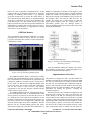
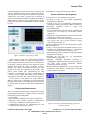
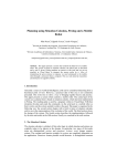
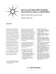
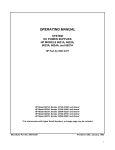
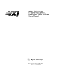
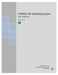
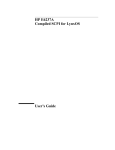
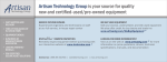
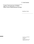
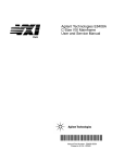
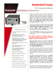
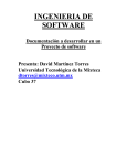
Session 12c6
Electronics Laboratory Practices Based on Virtual Instrumentation
P. Marino1, J. Nogueira2 and H. Hernandez3
E.T.S. Ingenieros Industriales. Departamento de Tecnologia Electronica
Universidad de Vigo, Apdo Oficial 36200 Vigo-Spain
1
Doctor on Telecommunications Engineering, [email protected]
2
Telecommunications Engineer, [email protected]
3
Electronic Engineer, [email protected], [email protected].
Abstract - The authors present an ATE system designed for
teaching practices about programmable electronic
instrumentation, by means of GPIB and VXI instruments
connected to a local area network (LAN). The aim of this
system intended for students of electronic engineering, is the
introduction of more relevant technologies involved in
hardware instrumentation for ATE applications, besides the
handling of their software environments for developing
programs.
LAN [5]. The interface between LAN and GPIB bus is made
with the Gateway LAN HP-IB HP E2050 [6]. The VXI bus
[2][7][8] is configured in a mainframe for instrument
modules in size C cards, and connected to the LAN through
the GPIB bus, being its software development tool the
environment VEE 4.0 from HP [9][10][11]. The figure 1
shows the ATE system configuration (SIP).
Introduction.
Teaching electronic instrumentation for engineering
students, has a great impact about their basic training on
technologies oriented to design systems for: process control,
product verification, services operation, quality analysis,
etc., over all economic sectors. The growing advance in
microelectronics given its continuos reduction in cost and
increasing processing power and lower size, with higher
performance of software packages, have boosted the
presence of powerful systems for automated test equipment
(ATE), based on programmable instrumentation [1].
In 90´s decade programmable instrumentation based on
GPIB and VXI [2] buses has reached a great spread,
allowing ATE systems design with multiple computer
platforms and several operating systems, creating the
“virtual instrument” concept. Currently the advance impulse
for GPIB performances and new architectures for
programmable instruments is sustained from manufactures,
users and researchers. For example, National Instruments
manufacturer introduced respectively the HS488
specification in 1993 oriented to reach a maximum byte rate
of 8 MBps in GPIB, and the PXI (PCI eXtensions for
Instrumentation) architecture in 1997, based on Compact
PCI [3][4], for modular instruments over electronic cards.
ATE System Description.
In their digital communications laboratory the authors have
designed a programmable instrumentation system (SIP)
based on IEEE 488 (GPIB) and VXI (VME eXtensions for
Instrumentation) buses, where the GPIB bus connects all
programmable instruments to laboratory’s PCs by means a
Figure 1. ATE system configuration (SIP) of programmable
instrumentation laboratory.
The Gateway connects the lab’s PC network to the GPIB
bus following client/server model [2], where each PC
performs as a client and the Gateway as server [6] [12][13].
In this way applications running in clients can communicate
with instruments based in GPIB bus in a transparent mode
through LAN. This allows several students access to
programmable instruments and sharing in this way the SIP
resources. The Gateway can be installed in any place of
network, depending on instruments location and GPIB's
cable length. Instrument identification is reduced to a simple
logical address.
Table 1 summarizes the features of equipments that
conform the SIP: two GPIB rack-and-stack instruments (DC
power supply [14] and multimeter [15]), a VXI mainframe
[3][7][16] with eight connected instruments ([14][15] and
0-7803-5643-8/99/$10.00 © 1999 IEEE
November 10 - 13, 1999 San Juan, Puerto Rico
29th ASEE/IEEE Frontiers in Education Conference
12c6-6
Session 12c6
[17] to [25]), the Gateway, and a PC with WATCH_GPIB
software developed by the authors that performs the bus
monitor function (paragraph 4).
Figure 2 depicts the software/firmware architecture of
SIP where each client computer, under operating system
Windows 95/NT and with VEE tool, manages the intended
programs to control instruments (SICL: Standard Instrument
Control Library) and LAN access (TCP/IP). The Gateway
has the network server software and adequate firmware for
implementing the interface between instruments and LAN.
The rack-and-stack GPIB instruments include the firmware
with bus drivers. Command module (slot 0 of chassis) from
VXI mainframe [17][22] incorporates the needed drivers for
VXI/GPIB interface. The PC Bus Monitor only takes the
signals from GPIB bus lines for displaying them on the
screen (paragraph 4).
The VEE (Visual Engineering Environment) tool is a
graphic programming language particularly designed for
driving programmable instruments. When the instruments
are connected to GPIB bus, the student send commands and
data following the training program by means of the LAN’s
PC. That PC will receive the replay and will perform data
analyzing, displaying graphic results or storing data for later
processing.
Development of Training Program.
The growing technological development in the
programmable instrumentation field, has allowed to authors
the implementation of applied research projects with these
kinds of instruments [1], and applications oriented to
teaching electronics. In this way one of largely applications
of VXI bus has been the automation of measurement and
testing over electronic circuits implemented by the students.
Simultaneously have been designed practices oriented to
evaluation and analysis of GPIB bus activity. The students
have access to SIP through PC´s connected to LAN, with the
VEE programming tool and SICL libraries (Figure 2), that
respectively allow implementing the measurement and
testing application and mastering the instruments. Also the
students can see the commands and data behavior through
GPIB bus by means a PC devoted to this task (Figure 1: Bus
Monitor).
Figure 2. Software/firmware architecture of SIP.
For easing the control of programmable instruments in
the development of ATE systems, usually are selected high
level programming languages such as C, C++, Visual Basic,
and so on. In this application is used the VEE programming
language that allows simplifying the task of interface design,
data acquisition, processing and displaying of results.
Table 2. Comparison between control types of instruments.
Table 1. Features of equipments that conform the SIP.
There are three control types of instruments in VEE
[26][27][28]: Direct I/O, Drivers, and PC Plug-in I/O, which
main features are shown in table 2. Laboratory practices
have been designed in order to easily introduce the students
about the three control types and acquaint them with
application needs and available tools. This way is justified
since this application does not use the PC Plug-in I/O
alternative, given it needs a particular card (VXIplug&play)
for implementing the interface, contrary to the cases of
Direct I/O and Drivers. Although Direct I/O requires the
knowledge of SICL´s instructions, nevertheless it provides
high communication speed and does not need the instrument
driver, the control type most frequently used in advanced
practices. Otherwise VEE gives a new object called
Multidevice Direct I/O that gets the control of several
instruments through the edition of only one object. The
controllers can be the control panel of the instrument (Panel
0-7803-5643-8/99/$10.00 © 1999 IEEE
November 10 - 13, 1999 San Juan, Puerto Rico
29th ASEE/IEEE Frontiers in Education Conference
12c6-7
Session 12c6
Driver) or a part of controller (Component Driver). In this
application the use of instrument control tools is oriented to
teaching, and handling control panels is very important
given that students learn to operate the whole choices of
each instrument easily. When there is no enough knowledge
about SICL´s instructions or choices of an instrument, the
Component Driver is the best solution because it provides
higher speed and only sends and receives the needed data for
implementing a particular task. Also this object has a list of
instructions and information for supporting the learning
about choices of each instrument.
GPIB bus, or displaying stored data in a file (Figure 3). This
program loads in the computer memory an interrupt control
routine and associates it to parallel port (IRQ7). The line
SRQ (Service Request) from GPIB bus [5][8] is used to fire
the interrupt routine and read the data from bus. For
avoiding the possible loss of data because of GPIB bus
higher speed compared with the reading speed of a
conventional parallel port, the interrupt routine of
WATCH_GPIB program stops temporarily bus activity until
reading the suitable data.
GPIB Bus Monitor.
The programmable instrumentation GPIB bus is a parallel
connection bus in which all devices share the line signals
[3][5][29], and requires the existence of some equipment for
mastering those signals.
Figure 4. Flowcharts for implementing and designing
laboratory practices.
Using the GPIB Bus Monitor the students can visualize
the commands and data that is sending through the bus a
particular instrument from SIP (Figure 1).
Figure 3. Screen of WATCH_GPIB program.
Implementation of Practices.
The GPIB Bus Monitor (Figure 1) designed for teaching
the IEEE 488 instrumentation bus, allows to display in real
time, and without lost of information the signal lines that
conform the GPIB bus. Given that a device can only access
the bus when it is addressed, the GPIB Bus Monitor must
not be a bus device since it must read the state continuously,
and for this reason it must not have any address,
consequently it does not exist from the controller and the
whole bus devices point of view.
The GPIB Bus Monitor has been implemented by means
of a PC under MS-DOS (Table 1). The GPIB interface cards
able to connect a PC to the bus do not allow the access to it
in a different time to the card has been addressed by the
controller, and therefore are not useful for this purpose. For
this reason is used an I/O Card adapted for reading the eight
data lines and the eight control lines of GPIB bus. The Bus
Monitor runs the WATCH_GPIB program that allows
gathering and displaying in real-time the available data on
The practices are designed in such a way that students can
handle the development environment and visualize the GPIB
bus. The two first practices are oriented to introduce them
the VEE tool and explaining SIP configuration. Both are
shown in auto-learning form and introduce step-by-step the
method of using the VEE environment, and the control of
instruments for making the practices, according the
flowchart of figure 4a.
Following practices allow students developing their own
programs using existing tools, and at any time they can
access directly to the SIP for connecting their electronic
circuits under test. For example, the practice three is oriented
to design a VEE program using the needed instruments for
implementing Bode´s diagrams (module and phase) of a RC
circuit frequency response. Also shown to the students are
the choices used to identify and compare the three control
types of instruments (Table 2), and the way VEE objects are
0-7803-5643-8/99/$10.00 © 1999 IEEE
November 10 - 13, 1999 San Juan, Puerto Rico
29th ASEE/IEEE Frontiers in Education Conference
12c6-8
Session 12c6
connected following respectively the flow of execution and
sequence. Emphasized is the control of instruments (Figure
4b) with the aim that students can identify correctly the
working tools. The results of this practice are depicted in
figure 5. This interaction with the development environment
allows students a better use of the graphic language and the
handling of the powerful mathematical functions provided
by VEE.
Figure 5. Instance of a practice in VEE
Other example is practice nine, devoted to the automated
testing of electronic boards, in which the students have a
board designed for teaching electronic devices, with the aim
of designing a graphical interface able to display the results
obtained from testing the whole components of board.
Basically the control of instruments is made given input
signals to the board and, supported by HP E1465A relay
matrix switch module [20], implementing the right
connection of instruments for making measurements of
resistence, AC/DC voltages and currents, period, frequency
and polarity test of diodes. The results are shown in figure 6.
In each practice is the optional use of the GPIB Bus
Monitor, which shows continuously the bus information;
sharing this task with the bus monitoring function provided
by VEE provides an useful tool when SICL instructions are
applied.
§Performances of HP-VEE working environment.
Results and Future Developments.
From the point of view of students the results are:
§Accessing to high cost and modern programmable
instrumentation equipment.
§Training in the use of programmable instrumentation,
currently unavoidable in a growing number of enterprises.
§Knowledge acquisition about a largely used
instrumentation bus.
§Use of instrumentation buses like general communication
resources if it were needed (i.e.: file transfers between
computers).
§Displaying an instrumentation bus control signals, besides
implementing electronic circuits testing.
§Generalization of SIP from general purpose practices to
more specific ones such as power electronics, engines
control, network analysis, etc.
Future developments about new advanced practices and the
SIP configuration are:
§Using a VXI register-based breadboard module [25] for
designing new compatible instruments (i.e.: A/D and D/A
converters, sensors and effectors conditioners, etc.).
§Implementing automatic evaluation of student throughput
during their training time.
§Including the new PXI bus for programmable
instrumentation (paragraph 1).
§Migrating compatible instrument controllers to
VXIplug&play standard currently in growing acceptance,
and using VISA (Virtual Instrument Software
Architecture) libraries [2][3][30].
§Remote training through Internet over the developed SIP.
Experiments with Mixteca Technological University
(Oaxaca, Mexico) are started.
Background Requirements.
The set of computer assisted practices designed for teaching
programmable instruments to students, requires from them
the following previous background:
§Circuits theory.
§Basic electronic foundations and electronic components.
§Experience using manual electronic instrumentation
(Oscilloscope, multimeter, function generator, etc.).
§Communication protocols for understanding the SIP
configuration which have been trained.
Figure 6. Interface of automated testing program for
electronic boards
0-7803-5643-8/99/$10.00 © 1999 IEEE
November 10 - 13, 1999 San Juan, Puerto Rico
29th ASEE/IEEE Frontiers in Education Conference
12c6-9
Session 12c6
Conclusions.
The use of communications networks for implementing
laboratory
practices
based
on
programmable
instrumentation, introduces electronic engineering students
to designing, configuring, and developing distributed ATE
systems. This work introduces a programmable
instrumentation system (SIP) development with GPIB and
VXI instruments connected to PC´s by means of a LAN. The
training program is started with the introduction to
knowledge of VEE programming tool, and follows
implementing test and measurements over electronic circuits
designed by students. Also are added practices for evaluating
and analyzing GPIB´s bus signals.
Finally basic knowledge required from students are
defined in order to obtain the best progress from practices,
and are analyzed the obtained results from the point of view
of students. Also are introduced the future developments that
authors are involved for improving both programmable
instrumentation practices and ATE system that runs them.
Acknowledgements.
This work has been sponsored by R&D NATIONAL
SECRETARY
AND
CICYT
from
CENTRAL
GOVERNMENT (Madrid, Spain) inside of research project,
Ref. TIC97-0414.
References.
[1] Mariño, P. & Domínguez, M. A.: “Image Processing and
Automated Testing in Flexible Manufacturing Systems”.
Proceedings of the 37th SICE Annual Conference,
IEEE98TH 8377, pp. 1121-1126, Chiba (Japan), July 29-31,
1998.
[2] HEWLETT PACKARD: Test System and VXI Products
Catalog. Hewlett-Packard Company, 1997.
[3] NATIONAL INSTRUMENTS: Instrumentation
Catalogue: Measurement and Automation. National
Instruments, 1998.
[4] NATIONAL INSTRUMENTS: PXI Specification
Rev.1.0, National Instruments, 1997.
[5] Mariño, P.: Enterprise-wide communications: standards,
networks and services. RA-MA, Madrid (Spain), 1995.
[6] HEWLETT PACKARD: HP E2050 LAN/HP-IB Gateway.
Hewlett-Packard Company, 1996.
[7] Black, J. (editor): The system engineer’s handbook.
Academic Press, 1992.
[8] Mandado, E., Mariño, P. & Lago, A.: Electronic
Instrumentation. Marcombo, Barcelona (Spain), 1995.
[9] HEWLETT PACKARD: Building an Operator Interface
with HP VEE. Hewlett-Packard Company, 1995.
[10] HEWLETT PACKARD: Exploring HP VEE. HewlettPackard Company, 1995.
[11] HEWLETT PACKARD: How to Use HP VEE.
Hewlett-Packard Company, 1995.
[12] HEWLETT PACKARD: Installing the HP-IB Interface.
Hewlett-Packard Company, 1994.
[13] HEWLETT PACKARD: HP 82335, 82340 & 82341HP-IB
Interface. Hewlett-Packard Company, 1996.
[14] HEWLETT PACKARD: Operating Manual, System DC
Power supplies, HP models 6621A, 6622A, 6623A, 6624A
and5527A. Hewlett-Packard Company, 1993.
[15] HEWLETT PACKARD: HP 3478A Multimeter:
Operator’s Manual. Hewlett-Packard Company, 1988.
[16] TEKTRONIX: VXIbus System Specifications Revision
1.4. Tektronix Inc., May 1992
[17] HEWLETT PACKARD: High-Power Mainframe HP
E1401A: User’s/Service Manual. Hewlett-Packard Company,
1992.
[18] HEWLETT PACKARD: HP E1410A 6 ½ Digit
Multimeter: User’s Manual. Hewlett-Packard Company, 1992.
[19] HEWLETT PACKARD: HP E1445A Arbitrary Function
Generator. Hewlett-Packard Company, 1992.
[20] HEWLETT PACKARD: 16x16, 4x64, and 8x32 Relay
Matrix Switch Modules HP E1465A/E1466A/E1467A:
User’s
[21] HEWLETT PACKARD: C-Size VXIbus Systems:
Configuration Guide. Hewlett-Packard Company, 1994.
[22] HEWLETT PACKARD: Command Module HP E1406A:
User’s Manual. Hewlett-Packard Company, 1994.
[23] HEWLETT PACKARD: Universal Counter HP E1420B:
User’s Manual. Hewlett-Packard Company, 1994.
[24] HEWLETT PACKARD: Digitizing Oscilloscope HP
E1428A: User’s Manual. Hewlett-Packard Company, 1994.
[25] HEWLETT PACKARD: HP E1490C C-Size VXIbus
Register-Based Breadboard Module: User’s Manual. HewlettPackard Company, 1996.
[26] HEWLETT PACKARD: HP I/O Libraries. HewlettPackard Company, 1996.
[27] HEWLETT PACKARD: Controlling Instruments with
HP VEE. Hewlett-Packard Company, 1998.
[28] HEWLETT PACKARD: Getting Started with HP VEE.
Hewlett-Packard Company, 1998.
[29] Caristy, J.: IEEE 488 General Purpose Instrumentación
Bus Manual. Academic Press, 1989.
[30] Helsel R.: Visual programming with HP VEE. HewlettPackard Professional Books, third edition 1998.
manual. Hewlett-Packard Company, 1993.
0-7803-5643-8/99/$10.00 © 1999 IEEE
November 10 - 13, 1999 San Juan, Puerto Rico
29th ASEE/IEEE Frontiers in Education Conference
12c6-10