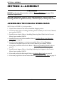
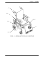
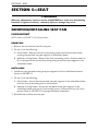
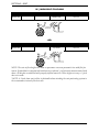
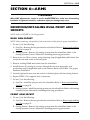
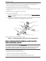
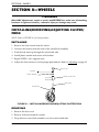
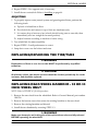
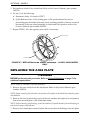
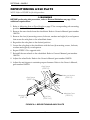
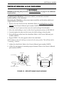
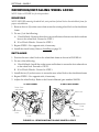
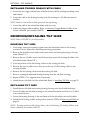
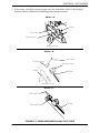
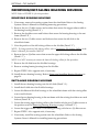
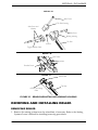
1
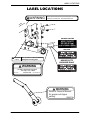
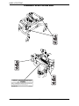
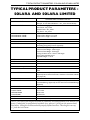
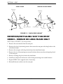
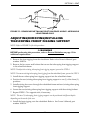
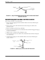
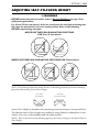
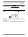
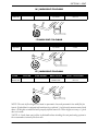
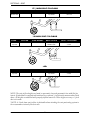
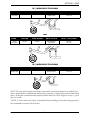
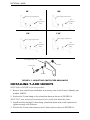
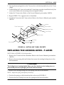
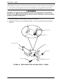
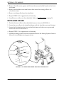
Service Manual
Solara™and
Solara™Limited
DEALER: Keep this manual. The
procedures in this manual MUST be
performed by a qualified technician.
For more information regarding
Invacare products, parts, and services,
please visit www.invacare.com
WARNING
THE PROCEDURES IN THIS MANUAL MUST BE PERFORMED BY A
QUALIFIED TECHNICIAN.
DO NOT SERVICE OR OPERATE THIS EQUIPMENT WITHOUT
FIRST READING AND UNDERSTANDING THIS MANUAL AND THE
OWNER’S MANUAL, PART NUMBER 1080556. IF YOU ARE UNABLE
TO UNDERSTAND THE WARNINGS, CAUTIONS, AND
INSTRUCTIONS, CONTACT A HEALTHCARE PROFESSIONAL,
DEALER OR A QUALIFIED TECHNICIAN BEFORE ATTEMPTING
TO USE THIS EQUIPMENT - OTHERWISE INJURY OR DAMAGE
MAY RESULT.
NOTE: Updated versions of this manual are available on www.invacare.com.
Solara™and Solara™Limited
2
Part No 1085787
SPECIAL NOTES
SPECIAL NOTES
WARNING/CAUTION notices as used in this manual apply to hazards or unsafe
practices which could result in personal injury and/or property damage.
NOTICE
THE INFORMATION CONTAINED IN THIS DOCUMENT IS SUBJECT TO
CHANGE WITHOUT NOTICE.
WHEELCHAIR USER
As a manufacturer of wheelchairs, Invacare endeavors to supply a wide variety of
wheelchairs to meet many needs of the end user. However, final selection of the
type of wheelchair to be used by an individual rests solely with the user and his/her
healthcare professional capable of making such a selection.
TIE-DOWN RESTRAINTS AND SEAT RESTRAINTS
Invacare recommends that wheelchair users NOT be transported in vehicles of any
kind while in wheelchairs. As of this date, the Department of Transportation has not
approved any tie-down systems for transportation of a user while in a wheelchair, in
a moving vehicle of any type.
It is Invacare’s position that users of wheelchairs should be transferred into
appropriate seating in vehicles for transportation and use be made of the restraints
made available by the auto industry. Invacare cannot and does not recommend any
wheelchair transportation systems.
SEAT POSITIONING STRAP
ALWAYS wear your seat positioning strap.
The seat positioning strap is a positioning belt only. It is not designed for use as a
safety device withstanding hight stress loads such as auto or aircraft safety belts. If
signs of wear appear, belt MUST be replaced immediately.
As regards restraints - seat/chest positioning straps - it is the obligation of the DME
dealer, therapists and other healthcare professionals to determine if a seat/chest
positioning strap is required to ensure the safe operation of this equipment by the
user. SERIOUS INJURY CAN OCCUR IN THE EVENT OF A FALL FROM A
WHEELCHAIR.
WARNING
Invacare prodcuts are specifically designed and manufactured for use in conjunction
with Invacare accessories. Accessories designed by other manufacturers have not
been tested by Invacare and are not recommended for use with Invacare products.
Part No 1085787
3
Solara™ and Solara™Limited
TABLE OF CONTENTS
TABLE OF CONTENTS
SPECIAL NOTES ................................................................................ 3
REGISTER YOUR PRODUCT................................................................ 6
LABEL LOCATIONS ........................................................................... 9
TYPICAL PRODUCT PARAMETERS - SOLARA AND SOLARA LIMITED 11
SECTION 8— GENERAL GUIDELINES ................................................. 13
Information for Healthcare Professionals/Assistants .......................................................................13
Anterior (Forward) Tilt......................................................................................................................13
Stability- All Models .................................................................................................................................14
Stability - All Models Except Recliners............................................................................................14
Stability - Recliner Models Only .......................................................................................................15
Operating Information.............................................................................................................................15
Weight Limitation.....................................................................................................................................16
SECTION 9—MAINTENANCE............................................................ 17
Maintenance Safety Precautions ............................................................................................................17
Suggested Maintenance Procedures .....................................................................................................17
SECTION 10—SAFETY INSPECTION/TROUBLESHOOTING ................... 18
Safety Inspection Checklists...................................................................................................................18
Troubleshooting........................................................................................................................................19
SECTION 11—ASSEMBLY.................................................................. 20
Assembling the Solara Wheelchair.......................................................................................................20
SECTION 12—SEAT.......................................................................... 22
Removing/Installing Seat Pan .................................................................................................................22
Flush Mount...........................................................................................................................................22
2 inch Drop Mount..............................................................................................................................23
Removing/Installing Seat Pan Drop Hooks - Medium or Long Frame Only ...............................24
Adjusting/Removing/Installing Telescoping Front Rigging Support ...............................................25
Removing/Installing Sector Block..........................................................................................................26
Adjusting Seat-to-Floor Height..............................................................................................................27
SECTION 13—ARMS......................................................................... 33
Removing/Installing Dual Point Arm Sockets.....................................................................................33
Rear Arm Socket..................................................................................................................................33
Front Arm Socket ................................................................................................................................33
Replacing/Repositioning Cantilever Arm Locking Lever .................................................................34
Adjusting Cantilever Arm Angle ...........................................................................................................35
Installing T-Arm Sockets.........................................................................................................................36
Replacing the Locking Lever - T-Arms ................................................................................................37
Part No 1085787
4
Solara™and Solara™Limited
SECTION 14—BACK ........................................................................ 39
Removing/Installing/Adjusting Back Release Cord ............................................................................39
Removing/Installing Back Release Cord..........................................................................................39
Adjusting Back Release Cord ............................................................................................................39
Adjusting Back Angle ...............................................................................................................................40
Removing/Installing the Spreader Bar ..................................................................................................41
Removing ...............................................................................................................................................41
Installing..................................................................................................................................................42
Removing/Installing the Back Canes.....................................................................................................43
Removing ...............................................................................................................................................43
Installing..................................................................................................................................................43
SECTION 15—WHEELS...................................................................... 44
Installing/Removing/Adjusting Caster/Fork.........................................................................................44
Installing..................................................................................................................................................44
Removing ...............................................................................................................................................44
Adjusting ................................................................................................................................................45
Replacing/Repairing the Tire/Tube .......................................................................................................45
Replacing Rear Wheel Handrim - 20 or 22 inch Wheel Only.......................................................45
Replacing the Axle Plate..........................................................................................................................46
Repositioning Axle Plate .........................................................................................................................48
Repositioning Axle Bushing ....................................................................................................................49
Removing/Installing Wheel Locks .........................................................................................................50
Removing ...............................................................................................................................................50
Installing..................................................................................................................................................50
SECTION 16—TILT-IN-SPACE .......................................................... 52
Removing/Installing Trigger Release Lever with Cable....................................................................52
Removing Trigger Release with Cable ............................................................................................52
Installing Trigger Release with Cable ..............................................................................................53
Removing/Installing Tilt Slide .................................................................................................................53
Removing Tilt Slide ..............................................................................................................................53
Installing Tilt Slide ................................................................................................................................53
Removing/Installing Bearing Housing ...................................................................................................55
Removing Bearing Housing ................................................................................................................55
Installing Bearing Housing ..................................................................................................................55
Removing and Installing Roller ..............................................................................................................56
Removing Roller...................................................................................................................................56
Installing Roller .....................................................................................................................................57
LIMITED WARRANTY ...................................................................... 59
Part No 1085787
5
Solara™and Solara™Limited
REGISTER YOUR PRODUCT
REGISTER YOUR PRODUCT
The benefits of registering:
1.
2.
3.
4.
5.
Safeguard your investment.
Ensure long term maintenance and servicing of your purchase.
Receive updates with product information, maintenance tips, and industry news.
Invacare can contact you or your provider, if servicing is needed on your product.
It will enable Invacare to improve product designs based on your input and needs.
Register ONLINE at www.invacare.com
- or Complete and mail the form on the next page
Any registration information you submit will be used by Invacare Corporation only, and
protected as required by applicable laws and regulations.
Solara™and Solara™Limited
6
Part No 1085787
PRODUCT REGISTRATION FORM
Register ONLINE at www.invacare.com - or Complete and mail this form
Name _______________________________________________________________
Address _____________________________________________________________
City ___________________ State/Province __________
Zip/Postal Code ________
Email ___________________________________ Phone No. _________________
Fold
here
Invacare Model No. ______________________ Serial No. __________________
Purchased From _________________________ Date of Purchase:___________
Cut Along Line
1. Method of purchase: (check all that apply)
❏ Medicare
❏ Insurance
❏ Medicaid ❏ Other
__________________________
2. This product was purchased for use by: (check one)
❏ Self
❏ Parent
❏ Spouse
❏ Other
3. Product was purchased for use at:
❏ Home
❏ Facility
❏ Other
4. I purchased an Invacare product because:
❏ Price
❏ Features (list features) _________________________________________
5. Who referred you to Invacare products? (check all that apply)
❏ Doctor ❏ Therapist ❏ Friend ❏ Relative ❏ Dealer/Provider ❏ Other_________
❏ Advertisement (circle one): TV, Radio, Magazine, Newspaper
❏ No Referral_____
6. What additional features, if any, would you like to see on this product?
__________________________________________________________________________ Fold
7. Would you like information sent to you about Invacare products that may be available for a here
particular medical condition? ❏ Yes ❏ No
If yes, please list any condition(s) here and we will send you information by email and/or mail about
any available Invacare products that may help treat, care for or manage such condition(s):
__________________________________________________________________________
8. Would you like to receive updated information via email or regular mail about the Invacare
home medical products sold by Invacare's dealers? ❏ Yes ❏ No
9. What would you like to see on the Invacare website?
__________________________________________________________________________
10. Would you like to be part of future online surveys for Invacare products? ❏ Yes ❏ No
11. User's Year of birth: ______________________________________________________
If at any time you wish not to receive future mailings from us, please contact us at Invacare Corporation,
CRM Department, 39400 Taylor Parkway, Elyria, OH 44035, or fax to 877-619-7996 and we will remove
you from our mailing list.
To find more information about our products, visit www.invacare.com.
Cut Along Line
Fold
here
Fold
here
Invacare Product Registration Form
Please Seal with
Tape Before Mailing
LABEL LOCATIONS
LABEL LOCATIONS
WARNING
Detent balls should extend beyond the diameter of the axle
bushing for a positive lock. Keep detent balls clean.
SOLARA LIMITED
SOLARA
! WARNING Refer to Owner’s Manual BEFORE
1085306 adjusting axle mounting plate.
HEAVY DUTY
PACKAGE ONLY
WARNING
DO NOT OPERATE WITHOUT
THE ANTI-TIP TUBES
INSTALLED. P/N 60106X144
REV. 5/98
WARNING
Refer to Owner's Manual
for proper anti-tipper
setting.
1085379
Part No 1085787
9
Solara™ and Solara™Limited
LABEL LOCATIONS
TRANSPORT READY OPTION ONLY
Solara™ and Solara™Limited
10
Part No 1085787
TYPICAL PRODUCT PARAMETERS - SOLARA AND SOLARA LIMITED
TYPICAL PRODUCT PARAMETERS SOLARA AND SOLARA LIMITED
SOLARA AND SOLARA LIMITED
OVERALL WIDTH:
Seat Width + 8¼ inches
(Example: 16 inch Wide Wheelchair = 24¼ inches Overall Width)
OVERALL DEPTH:
Without Front Riggings
Short Frame - 29½ inches
Medium Frame - 32½ inches
Long Frame - 34½ inches
OVERALL HEIGHT
20 INCH BACK CANES:
24 INCH BACK CANES:
* Seat-to-Floor Height + 21 inches
* Seat-to-floor Height + 25 inches
SHIPPING WEIGHT:
57 lbs.
ANTI-TIPPERS
Standard
FOOTREST:
Swing-Away Footrest (Standard)
Articulating Swing-Away Footrest (Optional)
ARMRESTS:
Dual Point - Adjustable Height
Dual Point Fixed Height - Desk Length
Dual Point Fixed Height - Full Length
Locking Cantilever Arms - Desk or Full Length
Non-Locking Cantilever Arms
Adjustable Height - T-Arms
SEAT:
Optional
SEAT PAN COLOR:
Black
BACK:
Optional
BACK ANGLE ADJUSTMENT:
90° to 120°
REAR AXLE:
Quick-Release
Fixed
REAR WHEELS:
12 inches Pneumatic (Standard); 12 inch Pneumatic with flat free
(Optional); 20 and 22 inch Pneumatic, Urethane or Pneumatic with flat
free (Optional)
HANDRIMS:
Aluminum Handrims
CASTER SIZE:
6x2 inch with Precision Sealed Bearings (Standard): 8-inch with Precision Sealed Bearings (Optional); 6x1inch with Precision Sealed Bearings
(Optional).
SEAT WIDTH:
12 - 22 inches
SEAT DEPTH
SHORT FRAME
MEDIUM FRAME
LONG FRAME
15-17 inches
18-20 inches
20-22 inches
BACK HEIGHT:
20-24 inches
WHEEL LOCKS:
Push-to-Lock (Standard)
*NOTE: The seat-to-floor heights are based on pneumatic tires and pneumatic tires with flat free
inserts. If wheelchair is equipped with urethane tires, subtract ¼ inch from the measurements
listed above. All heights are measured with properly inflated new tires. These heights can vary
± ¼ inch due to tire wear.
Part No 1085787
11
Solara™and Solara™Limited
TYPICAL PRODUCT PARAMETERS - SOLARA AND SOLARA LIMITED
SOLARA AND SOLARA LIMITED
TILT-IN-SPACE:
Dual Cable Trigger Mechanism (Standard) - 45° of Tilt
RECLINER BACK:
Dual Cable Trigger Mechanism (Optional) 0-180° of Tilt
FRAME:
Steel
WEIGHT LIMITATION
SOLARA LIMITED:
SOLARA:
200 lbs (91kg)
250 lbs (114kg)
*NOTE: The seat-to-floor heights are based on pneumatic tires and pneumatic tires with flat free
inserts. If wheelchair is equipped with urethane tires, subtract ¼ inch from the measurements
listed above. All heights are measured with properly inflated new tires. These heights can vary
± ¼ inch due to tire wear.
Solara™and Solara™Limited
12
Part No 1085787
SECTION 1—GENERAL GUIDELINES
SECTION 1— GENERAL GUIDELINES
WARNING
SECTION 1 - GENERAL GUIDELINES contains important information for the safe
operation and use of this product. DO NOT use this product or any available
optional equipment without first completely reading and understanding these
instructions and any additional instructional material such as Owner’s Manuals,
Service Manuals or Instruction Sheets supplied with this product or optional equipment. If you are unable to understand the Warnings, Cautions or Instructions, contact a healthcare professional, dealer or technical personnel before attempting to
use this equipment - otherwise, injury or damage may occur.
INFORMATION FOR HEALTHCARE
PROFESSIONALS/ASSISTANTS
The Solara wheelchair MUST be operated by a healthcare professional or assistant when
in any tilt position.
ANTERIOR (FORWARD) TILT
DO NOT operate the wheelchair when the seat frame is in the anterior (forward) tilt
position (frame stops in the lower position and approximately 10° forward tilt). Serious
bodily injury may occur to the patient and/or the assistant(s).
Anterior (forward) tilt is a feature of this wheelchair designed for the use of a healthcare
professional or assistant only. Engagement of the anterior (forward) tilt must NEVER be
performed by the wheelchair user. When anterior (forward) tilt is needed, it must
ALWAYS be engaged by a healthcare professional or assistant. Make sure the occupant of
the wheelchair is properly positioned and always engage both wheel locks.
Part No 1085787
13
Solara™and Solara™Limited
SECTION 1—GENERAL GUIDELINES
STABILITY- ALL MODELS
N/A N/A
LOCKING COLLAR
USER CONIDITION
X
X
X
X
X
X
X
X
N/A
X
X
X
X
N/A N/A N/A
X
•
X
X
X
X
X
X
N/A N/A N/A
X
X
•
X
X
X
X
X
X
N/A
•
ANTI-TIPPERS
X
WHEEL LOCKS
X
WHEEL POSITION
X
WHEEL SIZE
X
CASTER POSITION
TILT ANGLE
•
X
CASTER SIZE
SEATING SYSTEM
X
TILT ANGLE
BACK ANGLE
X
SEATING SYSTEM
SEAT DEPTH
•
BACK ANGLE
BACK HEIGHT
SEAT DEPTH
NOTE: When changes
to the left hand column
occur, follow across the
chart and refer to the X
procedure to maintain
the proper stability,
safety and handling of
the wheelchair.
BACK HEIGHT
The back height, seat depth, back angle, seating system, tilt angle, seat height, size/
position of the rear wheels, size/position of the front casters, as well as the user condition
directly relate to the stability of the wheelchair. Any change to one (1) or any combination
of the eleven (11) may cause the wheelchair to decrease in stability. These adjustments
MUST be performed by a qualified technician.
N/A N/A N/A N/A
X
N/A N/A
X
N/A N/A N/A N/A N/A N/A N/A
X
CASTER SIZE
X
N/A
X
N/A N/A
•
X
X
X
N/A
X
X
X
CASTER POSITION
X
N/A
X
N/A N/A
X
•
X
X
N/A
X
X
X
WHEEL SIZE
X
N/A
X
N/A N/A
X
X
•
X
N/A
X
X
X
WHEEL POSITION
X
N/A
X
N/A N/A
X
X
X
•
N/A
X
X
X
USER CONDITION
X
X
X
X
X
X
X
X
X
•
SEAT HEIGHT
X
N/A
X
X
X
X
X
X
X
N/A
N/A N/A N/A
X
X
X
ALWAYS make sure that the wheelchair is stable before using the tilt-in-space.
Axle mounting plates have specific positions depending on the size of the rear wheels.
Using axle mounting plate positions other than those described in this manual will cause
an unsafe anti-tipper height as well as a possible forward seat dump. NEVER use an axle
mounting plate position other than those described in this manual-otherwise injury or
damage may result.
STABILITY - ALL MODELS EXCEPT RECLINERS
To maintain maximum stability, position the rear wheels in the most rearward position in
the axle mounting plate. Moving the rear wheels to any of the other mounting positions
causes the wheelchair to decrease in stability.
If moving the rear wheels to any forward position, ensure the wheelchair is stable before
using.
ALWAYS ensure stability before using maximum amount of tilt-in-space or moving the
rear wheels forward. Test wheelchair before it is occupied by the end user to ensure safety.
Solara™and Solara™Limited
14
Part No 1085787
SECTION 1—GENERAL GUIDELINES
STABILITY - RECLINER MODELS ONLY
Before using any recline position of this wheelchair, make sure the rear wheels are in the
most rearward position in the axle mounting plate to maintain the stability of the
wheelchair. DO NOT change the handling/maneuverability of the wheelchair by moving
the rear wheels to any of the forward positions. Moving the rear wheels to any of the
forward positions will change the center of gravity of the wheelchair, making the
wheelchair less stable.
ALWAYS make sure that the wheelchair is stable in the full reclined (back at 180°) position
and the full upright (back at 90°) position before using the recliner option.
Before using the recliner option, make sure the anti-tipper wheel assemblies are in the
lowest adjustment hole (adjustment hole closest to the ground/floor).
ALWAYS engage both wheel locks while reclining or inclining (reverse recline) the
wheelchair.
Both gas cylinders MUST be operational and adjusted properly before using the recliner.
DO NOT operate the recliner option if only one (1) of the gas cylinders is operational or
adjusted properly.
Make sure the occupant of the wheelchair is properly positioned in the wheelchair before
reclining or inclining (reverse recline) to maintain maximum stability and safety.
When returning the occupant of the wheelchair to the full upright position, more body
strength will be required for approximately the last twenty (20) degrees of incline (reverse
recline). Make sure to use proper body mechanics (use your legs) or seek assistance to
avoid injury.
ALWAYS return the back to the upright position before lifting the wheelchair.
OPERATING INFORMATION
DO NOT overtighten hardware attaching to the frame. This could cause damage to the
frame tubing.
Unless otherwise noted, all service and adjustments should be performed while the
wheelchair is unoccupied.
DO NOT use the wheelchair unless it has the proper tire pressure (p.s.i.). DO NOT
overinflate the tires. Failure to follow these suggestions may cause the tire to explode and
cause bodily harm. The recommended tire pressure is listed on the side wall of the tire.
ALWAYS check foam grips for looseness before using the wheelchair. If loose, contact a
qualified technician for instructions.
The necessary back angle (90°, 100°, 110° or 120°) MUST be selected before repositioning
the rear wheels forward.
DO NOT operate the tilt-in-space if the trigger release levers and cables are not properly
adjusted to ensure that the tilt-in-space is locked in place when engaged.
DO NOT use any parts, accessories, or adapters other than those authorized by Invacare.
Part No 1085787
15
Solara™and Solara™Limited
SECTION 1—GENERAL GUIDELINES
DO NOT attempt to lift a wheelchair by lifting on any removable (detachable) parts.
Lifting by means of any removable (detachable) parts of a wheelchair may result in injury
to the user or damage to the wheelchair.
DO NOT use the spreader bar for lifting or transporting the wheelchair. DO NOT use the
spreader bar as a weight bearing support.
Invacare recommends that anti-tippers are attached at all times.
The seat positioning strap is a positioning belt only. It is not designed for use as a safety
device withstanding high stress loads such as auto or aircraft safety belts. If signs of wear
appear, belt must be replaced immediately.
WEIGHT LIMITATION
The Invacare Solara Limited wheelchair has a weight limitation of 200 lbs (91kg). The
Invacare Solara wheelchair has a weight limitation of 250 lbs (114kg).
Solara™and Solara™Limited
16
Part No 1085787
SECTION 2—SAFETY INSPECTION TROUBLESHOOTING
SECTION 2—SAFETY INSPECTION
TROUBLESHOOTING
SAFETY INSPECTION CHECKLISTS
Initial adjustments should be made to suit the end user’s personal body structure needs
and preference. After initial setup, perform these procedures every time the wheelchair is
serviced.
CAUTION
As with any vehicle, the wheels/casters and tires should be checked periodically for
cracks, flat spots and wear, and should be replaced.
❑ Ensure wheelchair rolls straight (no excessive drag or pull to one side).
❑ Ensure all hardware is tight.
❑ Ensure no bent or protruding metal on clothing guards.
❑ Ensure all fasteners on clothing guards are secure.
❑ Ensure arms are secure but easy to release and adjustment levers engage properly.
❑ Ensure adjustable height arms operate and lock securely.
❑ Ensure armrest pad sits flush against arm tube.
❑ Ensure seat and/or back upholstery have no rips.
❑ Ensure hand grips are not loose.
❑ Ensure trigger release cables completely release and handles return when released.
❑ Ensure sealed bearings and axle nut tension are correct.
❑ Ensure no excessive side movement or binding when rear wheels are lifted and spun.
❑ Inspect handrims for signs of rough edges or peeling finish.
❑ Ensure wheel/fork assembly has proper tension when caster is spun. Caster should
come to a gradual stop.
❑ Adjust bearing system if wheel wobbles noticeably or binds to a stop.
❑ Ensure all caster/wheel/fork/headtube fasteners are secure.
❑ Ensure wheel locks do not interfere with tires when rolling.
❑ Ensure wheel lock pivot points are free of wear and looseness.
❑ Ensure wheel locks are easy to engage.
❑ Inspect tires/casters for flat spots and wear.
❑ Check pneumatic tires for proper inflation.
Part No 1127114
17
Solara™ and Solara™Limited
SECTION 2—SAFETY INSPECTION TROUBLESHOOTING
WARNING
DO NOT use WD-40®, 3-in-1 oil®, or other penetrating lubricants on quick-release
axles. Otherwise, binding and/or damage to the wheelchair may occur.
❑ Clean quick-release axles with a Teflon® lubricant.
❑ Ensure axles are free from dirt, lint, etc.
❑ Ensure roller bearings are free from dirt, lint, etc.
❑ Adjust wheel locks as tires wear.
❑ Clean and wax all parts.
❑ Clean upholstery and armrests.
❑ Inspect seat positioning strap for any signs of wear. Ensure buckle latches. Verify
hardware that attaches strap to frame is secure and undamaged. Replace if necessary.
X
X
LOOSENESS
IN CHAIR
X
SQUEAKS AND
RATTLES
SLUGGISH TURN
/PERFORMANCE
X
CASTERS
FLUTTER
CHAIR VEERS
LEFT/RIGHT
TROUBLESHOOTING
SOLUTIONS
If pneumatic tires, check for correct and equal pressure.
X
X
X
Solara™ and Solara™Limited
X
Check for loose stem nuts/bolts.
Check that casters contact ground at the same time.
18
Part No 1127114
SECTION 3—MAINTENANCE
SECTION 3—MAINTENANCE
MAINTENANCE SAFETY PRECAUTIONS
WARNING
After ANY adjustments, repair or service and BEFORE use, make sure all attaching
hardware is tightened securely - otherwise injury or damage may result.
CAUTION
DO NOT overtighten hardware attaching to the frame. This could cause damage to
the frame tubing.
SUGGESTED MAINTENANCE PROCEDURES
WARNING
DO NOT use the wheelchair unless it has the proper tire pressure (p.s.i.). DO NOT
overinflate the tires. Failure to follow these suggestions may cause the tire to
explode and cause bodily harm.
As with any vehicle, the wheels, casters and tires should be checked periodically for
cracks and wear, and should be replaced.
1. Keep quick-release axles free of dirt and lint to ensure positive locking and proper
operation. Refer to the Owner’s Manual, part number 1080556.
WARNING
DO NOT use WD-40, 3-in-1 Oil, or other penetrating lubricants on quick-release
axles. Otherwise, binding and/or damage to the wheelchair may occur.
2. Clean quick-release axles once (1) a week with a Teflon lubricant.
3. Maintain proper tire pressure. If tires are pneumatic, recommended tire pressures will
be listed on the side wall of the tires.
4. Periodically adjust wheel locks in correlation to tire wear. Refer to the Owner’s
Manual, part number 1080556.
5. Make sure that all bolts are tight before operating wheelchair.
6. Keep tilt slides and roller bearings free of dirt and lint to ensure proper operation of
the tilt mechanism.
7. Perform safety inspections whenever the wheelchair is brought in for service. Refer to
Safety Inspection Checklists on page 17.
Part No 1085787
19
Solara™ and Solara™Limited
SECTION 4—ASSEMBLY
SECTION 4—ASSEMBLY
WARNING
BEFORE performing this procedure, refer to General Guidelines on page 13 for
additional requirements.
After ANY adjustments, repair or service and BEFORE use, make sure that all
attaching hardware is tightened securely - otherwise injury or damage may result.
ASSEMBLING THE SOLARA WHEELCHAIR
NOTE: Refer to FIGURE 4.1 for this procedure.
1. Unpack the contents of the Solara wheelchair shipping carton.
2. Unfold the back. Refer to Folding/Unfolding Back Assembly in the Owner’s Manual,
part number 1080556.
3. Install the rear wheels. Refer to Installing/Removing Rear Wheels in the Owner’s
Manual, part number 1080556.
4. Install the front caster/fork assemblies. Refer to Installing/Removing/Adjusting
Caster/Fork on page 44.
5. Install the front riggings or contracture assembly. Refer to Front Riggings or
Contracture Footplate Option in the Owner’s Manual, part number 1080556.
6. If necessary, install the wheel locks. Refer to Removing/Installing Wheel Locks on
page 50.
7. Install the anti-tippers. Refer to Installing/Adjusting Anti-tippers in the Owner’s
Manual, part number 1080556.
8. If necessary, adjust the back angle. Refer to Adjusting Back Angle on page 40.
9. If necessary, reposition the rear wheels.Refer to Repositioning Axle Plate on page 48.
Solara™and Solara™Limited
20
Part No 1085787
SECTION 4—ASSEMBLY
STEP 2
STEP 8
STEP 5
STEP 6
STEP 4
STEP 3
FIGURE 4.1 - ASSEMBLING THE SOLARA WHEELCHAIR
Part No 1085787
21
Solara™and Solara™Limited
SECTION 5—SEAT
SECTION 5—SEAT
WARNING
After any adjustments, repair or service and BEFORE use, make sure all attaching
hardware is tightened securely - otherwise injury or damage may occur.
REMOVING/INSTALLING SEAT PAN
FLUSH MOUNT
NOTE: Refer to FIGURE 5.1 for this procedure.
REMOVING
1. Remove the seat cushion from the seat pan.
2. Do one (1) of the following:
A. Short Frame - Remove the four (4) mounting screws and locknuts that secure
existing seat pan and seat pan supports to wheelchair frame.
B. Medium or Long Frame - Remove the six (6) mounting screws, locknuts and two
(2) coved spacers that secure the existing seat pan and seat pan supports to the
wheelchair frame.
INSTALLING
1. Install new seat pan and existing seat pan supports onto the wheelchair frame as
shown in FIGURE 5.1.
2. Do one (1) of the following:
A. Short Frame - Secure the seat pan and seat pan supports to the wheelchair frame
with the four (4) mounting screws and locknuts.
B. Medium or Long Frame - Secure the seat pan and seat pan supports to the
wheelchair frame with the six (6) mounting screws, locknuts and two (2) coved
spacers. Refer to FIGURE 5.1 for proper hardware orientation.
3. Reinstall seat cushion onto seat pan.
Solara™and Solara™Limited
22
Part No 1085787
SECTION 5—SEAT
SHORT FRAME
Wheelchair
Frame
MEDIUM OR LONG FRAME
Mounting Screws
Seat Pan
Seat Pan
Support
Coved Spacer
Locknuts
Locknuts
Mounting Screws
Seat Pan
Seat Pan
Support
Wheelchair Frame
FIGURE 5.1 - FLUSH MOUNT
2 INCH DROP MOUNT
NOTE: Refer to FIGURE 5.2 for this procedure.
1. Remove the seat cushion from the seat pan.
2. Remove the four (4) mounting screws and locknuts that secure existing seat pan to the
crossmembers.
3. Do one (1) of the following:
A. Short Frame - Remove seat pan from wheelchair.
B. Medium or Long Frame - Remove seat pan with drop hooks from the wheelchair.
4. Do one (1) of the following:
A. Short Frame - Install new seat pan onto the wheelchair as shown in FIGURE 5.2.
B. Medium or Long Frame - Install the new seat pan with drop hooks onto the
wheelchair as shown in FIGURE 5.2.
WARNING
After installation and BEFORE use, ensure drop hooks are flush and secured to the
side rails - otherwise injury or damage may occur.
5. Secure the new seat pan with the four (4) mounting screws and locknuts to the
crossmembers.
6. Reinstall seat cushion onto seat pan.
Part No 1085787
23
Solara™and Solara™Limited
SECTION 5—SEAT
SHORT FRAME
MEDIUM OR LONG FRAME
Mounting
Screws
Mounting
Screws
Crossmember
Locknuts
Crossmember
Drop
Hook
Seat Pan
Seat Pan
Locknuts
FIGURE 5.2 - 2 INCH DROP MOUNT
REMOVING/INSTALLING SEAT PAN DROP
HOOKS - MEDIUM OR LONG FRAME ONLY
NOTE: Refer to FIGURE 5.3 for this procedure.
1. Remove the seat cushion from the seat pan.
2. Remove the four (4) mounting screws that secure the seat pan with drop hooks to the
wheelchair frame.
3. Remove the seat pan with drop hooks from the wheelchair frame.
4. Remove the two (2) mounting screws and locknuts that secure the existing drop hook
to the seat pan.
5. Remove existing drop hook from the wheelchair.
6. Install new drop hook and secure with existing mounting screws and locknuts.
7. Repeat STEPS 4-6 for opposite side, if necessary.
8. Reinstall the seat cushion onto the seat pan.
Solara™and Solara™Limited
24
Part No 1085787
SECTION 5—SEAT
Mounting
Screws
Drop Hook
Drop Hook
Locknuts
FIGURE 5.3 - REMOVING/INSTALLING SEAT PAN DROP HOOKS - MEDIUM OR
LONG FRAME ONLY
ADJUSTING/REMOVING/INSTALLING
TELESCOPING FRONT RIGGING SUPPORT
NOTE: Refer to FIGURE 5.4 for this procedure.
WARNING
BEFORE performing this procedure, refer to General Guidelines on page 13 for
additional requirements.
1. Remove the front rigging from the wheelchair. Refer to the Owner's Manual, part
number 1080556.
2. Remove the hex screw and locknut that secure the telescoping front rigging support
to the wheelchair frame.
NOTE: To adjust the existing telescoping front rigging support, proceed to STEP 4.
NOTE: To remove existing telescoping front rigging from the wheelchair frame, proceed to STEP 3.
3. Install the new telescoping front rigging support into the wheelchair frame.
4. Position the new/existing telescoping front rigging support to one (1) of the three (3)
positions.
5. Install existing hex screw through the wheelchair frame and new/existing telescoping
front rigging support.
6. Secure the new/existing telescoping front rigging support with the existing locknut.
7. Repeat STEPS 1-7 for opposite side, if necessary.
NOTE: The two (2) telescoping front rigging supports can be positioned at different depths
depending on the needs of the user.
8. Install the front rigging onto the wheelchair. Refer to the Owner's Manual, part
number 1080556.
Part No 1085787
25
Solara™and Solara™Limited
SECTION 5—SEAT
Locknut
Wheelchair
Frame
Telescoping
Front Rigging
Support
Hex Screw
FIGURE 5.4 - ADJUSTING/REMOVING/INSTALLING TELESCOPING FRONT
RIGGING SUPPORT
REMOVING/INSTALLING SECTOR BLOCK
NOTE: Refer to FIGURE 5.5 for this procedure.
1. Remove the front rigging from the wheelchair. Refer to the Owner's Manual, part
number 1080556.
2. Remove the hex screw and washer that secure the existing sector block to the
wheelchair frame.
3. Remove existing sector block from wheelchair.
4. Position the new sector block on the wheelchair frame with the locking pin facing up
as shown in FIGURE 5.5
5. Apply Loctite™ to threads of the existing hex screw.
6. Securely tighten the new sector block to the wheelchair frame with the existing hex
screw and washer.
7. Install the front rigging onto the wheelchair. Refer to the Owner's Manual, part
number 1080556.
Hex Screw
Wheelchair
Frame
Washer
Locking Pin
FIGURE 5.5 - REMOVING/INSTALLING SECTOR BLOCK
Solara™and Solara™Limited
26
Part No 1085787
SECTION 5—SEAT
ADJUSTING SEAT-TO-FLOOR HEIGHT
WARNING
BEFORE performing this procedure, refer to General Guidelines on page 13 for
additional requirements.
For 20 and 22 inch rear wheels, there are restrictions for axle plate mounting that
will cause the wheelchair to be in an unsafe position. Refer to the following,
BEFORE repositioning axle plate.
NEVER USE THESE AXLE MOUNTING POSITIONS
FOR 20 or 22-inch wheels
NEVER USE THESE AXLE MOUNTING POSITIONS FOR 22-inch wheels
NOTE: The following illustration shows the two (2) mounting positions for the axle mounting
plate when determining Seat-to-Floor Height.
Axle Plate
Rounded DOWN
Axle Plate
Rounded UP
Seat-to-Floor Height is determined by measuring from the seat pan to the ground/floor.
The different Seat-to-Floor heights are possible by using different combinations of rear
wheels, caster size, fork assemblies and axle plate position.
NOTE: Refer to the charts on the following pages for the correct settings for the desired Seat-toFloor Height.
Part No 1085787
27
Solara™and Solara™Limited
SECTION 5—SEAT
After determining caster size and caster position needed, refer to Installing/Removing/
Adjusting Caster/Fork on page 44.
After determining rear wheel size, refer to the Owner's Manual, part number 1080556.
WARNING
After changing Seat-to-Floor Height, the anti-tippers MUST be adjusted BEFORE
using the wheelchair. Refer to Installing/Adjusting Anti-tippers in the Owner's Manual, part number 1080556.
16 INCH SEAT-TO-FLOOR
FORK
6 inch/
Top Hole
CASTER
REAR WHEEL
AXLE PLATE
SEAT-TO-FLOOR
6 inch
12 inch
Rounded Down/
Bottom 2 Holes
16 inch
*14 inch
NOTE: The seat-to-floor heights are based on pneumatic tires and pneumatic tires with flat free
inserts. If wheelchair is equipped with urethane tires, subtract ¼ inch from the measurements listed
above. All heights are measured with properly inflated new tires. These heights can vary ± ¼ inch
due to tire wear.
*NOTE: A 2-inch lower seat-to-floor is obtainable when attaching the seat pan/seating system to
the crossmembers instead of the seat rails.
Solara™and Solara™Limited
28
Part No 1085787
SECTION 5—SEAT
16¾ INCH SEAT-TO-FLOOR
FORK
6 inch/
Middle Hole
CASTER
REAR WHEEL
AXLE PLATE
SEAT-TO-FLOOR
6 inch
12 inch
Rounded Down/
Top 2 Holes
16¾ inch
*14¾ inch
17 INCH SEAT-TO-FLOOR
FORK
8 inch/
Upper Hole
CASTER
REAR WHEEL
AXLE PLATE
SEAT-TO-FLOOR
6x2 inch
12 inch
Rounded Down/
Top 2 Holes
17 inch
*15 inch
17½ INCH SEAT-TO-FLOOR
FORK
6 inch/
Bottom Hole
CASTER
REAR WHEEL
AXLE PLATE
SEAT-TO-FLOOR
6 inch
12 inch
Rounded Down/
Middle 2 Holes
17½ inch
*15½ inch
NOTE: The seat-to-floor heights are based on pneumatic tires and pneumatic tires with flat free
inserts. If wheelchair is equipped with urethane tires, subtract ¼ inch from the measurements listed
above. All heights are measured with properly inflated new tires. These heights can vary ± ¼ inch
due to tire wear.
*NOTE: A 2-inch lower seat-to-floor is obtainable when attaching the seat pan/seating system to
the crossmembers instead of the seat rails.
Part No 1085787
29
Solara™and Solara™Limited
SECTION 5—SEAT
FORK
6 inch/
Bottom Hole
CASTER
6 inch
17½ INCH SEAT-TO-FLOOR
REAR WHEEL AXLE PLATE
20 inch
Rounded Down/
Top 2 Holes
SEAT-TO-FLOOR
17½ inch
*15½ inch
18 INCH SEAT-TO-FLOOR
FORK
8 inch/
Top Hole
CASTER
REAR WHEEL
AXLE PLATE
SEAT-TO-FLOOR
8 inch
12 inch
Rounded Up/
Middle 2 Holes
18 inch
*16 inch
-ORFORK
8 inch/
Top Hole
CASTER
REAR WHEEL
AXLE PLATE
SEAT-TO-FLOOR
8 inch
20 inch
Rounded Down/
Top 2 Holes
18 inch
*16 inch
NOTE: The seat-to-floor heights are based on pneumatic tires and pneumatic tires with flat free
inserts. If wheelchair is equipped with urethane tires, subtract ¼ inch from the measurements listed
above. All heights are measured with properly inflated new tires. These heights can vary ± ¼ inch
due to tire wear.
*NOTE: A 2-inch lower seat-to-floor is obtainable when attaching the seat pan/seating system to
the crossmembers instead of the seat rails.
Solara™and Solara™Limited
30
Part No 1085787
SECTION 5—SEAT
18¼ INCH SEAT-TO-FLOOR
FORK
8 inch/
Lower Hole
CASTER
REAR WHEEL
AXLE PLATE
SEAT-TO-FLOOR
6x2 inch
12 inch
Rounded Down/
Middle 2 Holes
18¼ inch
*16¼ inch
-ORFORK
8 inch/
Lower Hole
CASTER
REAR WHEEL
AXLE PLATE
SEAT-TO-FLOOR
6x2 inch
20 inch
Rounded Down/
Top 2 Holes
18¼ inch
16¼ inch
19¼ INCH SEAT-TO-FLOOR
FORK
8 inch/
Bottom Hole
CASTER
REAR WHEEL
AXLE PLATE
SEAT-TO-FLOOR
8 inch
12 inch
Rounded Down/
Bottom 2 Holes
19¼ inch
*17¼ inch
NOTE: The seat-to-floor heights are based on pneumatic tires and pneumatic tires with flat free
inserts. If wheelchair is equipped with urethane tires, subtract ¼ inch from the measurements listed
above. All heights are measured with properly inflated new tires. These heights can vary ± ¼ inch
due to tire wear.
*NOTE: A 2-inch lower seat-to-floor is obtainable when attaching the seat pan/seating system to
the crossmembers instead of the seat rails.
Part No 1085787
31
Solara™and Solara™Limited
SECTION 5—SEAT
19¼ INCH SEAT-TO-FLOOR
FORK
8 inch/
Bottom Hole
FORK
8 inch/
Bottom Hole
CASTER
REAR WHEEL
AXLE PLATE
SEAT-TO-FLOOR
8 inch
20 inch
Rounded Down/
Middle 2 Holes
19¼ inch
*17¼ inch
CASTER
8 inch
-ORREAR WHEEL AXLE PLATE
22 inch
Rounded Down/
Top 2 Holes
SEAT-TO-FLOOR
19¼ inch
*17¼ inch
NOTE: The seat-to-floor heights are based on pneumatic tires and pneumatic tires with flat free
inserts. If wheelchair is equipped with urethane tires, subtract ¼ inch from the measurements listed
above. All heights are measured with properly inflated new tires. These heights can vary ± ¼ inch
due to tire wear.
*NOTE: A 2-inch lower seat-to-floor is obtainable when attaching the seat pan/seating system to
the crossmembers instead of the seat rails.
Solara™and Solara™Limited
32
Part No 1085787
SECTION 6—ARMS
SECTION 6—ARMS
WARNING
After ANY adjustments, repair or service and BEFORE use, make sure all attaching
hardware is tightened securely - otherwise injury or damage may occur.
REMOVING/INSTALLING DUAL POINT ARM
SOCKETS
NOTE: Refer to FIGURE 6.1 for this procedure.
REAR ARM SOCKET
NOTE: Before removing, note position of rear arm socket in back plate for proper reinstallation.
1. Do one (1) of the following:
A. Seat Pan - Remove the seat pan from the wheelchair. Refer to Removing/Installing
Seat Pan on page 22.
B. Seating System - Remove the seating system from the wheelchair. Refer to the
Seating Systems Owner’s Manual for installing/removing procedures.
2. Remove the two (2) hex screws, seat positioning strap (if applicable) and locknut that
secure the rear arm socket to the back plate.
3. Remove existing REAR arm socket from the wheelchair.
4. Install the two (2) existing hex screws through the new rear arm socket, seat
positioning strap (if applicable) and coved washers. Refer to FIGURE 6.1 for proper
hardware orientation.
5. Securely tighten the new rear arm socket to the back plate with the existing locknut.
6. Repeat STEPS 2-5 for opposite side, if necessary.
7. Do one (1) of the following:
A. Seat Pan - Install the seat pan onto the wheelchair. Refer to Removing/Installing
Seat Pan on page 22.
B. Seating System - Install the seating system onto the wheelchair. Refer to the Seating
Systems Owner’s Manual for installing/removing procedures.
FRONT ARM SOCKET
1. Do one (1) of the following:
A. Seat Pan - Remove the seat pan from the wheelchair. Refer to Removing/Installing
Seat Pan on page 22.
B. Seating System - Remove the seating system from the wheelchair. Refer to the
Seating Systems Owner’s Manual for installing/removing procedures.
Part No 1085787
33
Solara™and Solara™Limited
SECTION 6—ARMS
2. Remove the locknut that secures the front arm socket to the wheelchair frame.
3. Remove existing front arm socket from the wheelchair.
4. Install the new front arm socket into the wheelchair frame.
5. Securely tighten the new front arm socket to the wheelchair frame with the existing
locknut.
6. Repeat STEPS 2-5 for opposite side, if necessary.
7. Do one (1) of the following:
A. Seat Pan - Install the seat pan onto the wheelchair. Refer to Removing/Installing
Seat Pan on page 22.
B. Seating System - Install the seating system onto the wheelchair. Refer to the Seating
Systems Owner's Manual for installing/removing procedures.
Back Plate
Coved Washers
Locknuts
REAR Arm Socket
Wheelchair Frame
Locknut
Hex Screws
FRONT Arm Socket
NOTE: Seat positioning strap NOT shown for clarity.
FIGURE 6.1 - REMOVING/INSTALLING DUAL POINT ARM SOCKETS
REPLACING/REPOSITIONING CANTILEVER
ARM LOCKING LEVER
CAUTION
The locking mechanism is spring loaded. Place your free hand over the locking
mechanism to prevent the parts from springing out of the cantilever arm.
NOTE: Refer to FIGURE 6.2 for this procedure.
1. Flip the cantilever arm up and out of the way.
2. Unscrew the actuator from the locking mechanism.
3. Remove the locking mechanism and spring from the cantilever arm.
Solara™and Solara™Limited
34
Part No 1085787
SECTION 6—ARMS
NOTE: Inspect the spring for damage and replace if necessary.
4. Slide the new locking mechanism and spring into the cantilever arm.
5. Position the angled portion of the locking mechanism in one (1) of two (2) ways (Detail
“A”):
A. Angled Portion Facing Up - Arm will flip up.
B. Angled Portion Facing Down - Arm will flip down.
6. Push and hold the locking mechanism into the cantilever arm.
7. Screw the actuator into the locking mechanism mounting hole.
8. Flip the cantilever arm up/down to lock in place.
9. Pull up/down on the cantilever arm to ensure it has locked in place.
Mounting
Hole
DETAIL "A" SIDE VIEW OF
LOCKING MECHANISM
Spring
Cantilever
Arm
Angled Portion of
Locking Mechanism
Actuator
Locking
Mechanism
FIGURE 6.2 - REPLACING/REPOSITIONING CANTILEVER ARM LOCKING
LEVER
ADJUSTING CANTILEVER ARM ANGLE
NOTE: Refer to FIGURE 6.3 for this procedure.
NOTE: This adjustment is recommended if the back angle has been changed.
1. Flip the cantilever arm up and out of the way.
2. Remove the locknut that secures the locking pin to the arm adjustment plate.
3. Refer to FIGURE 6.3 to determine the mounting hole in the arm adjustment plate that
will be used to correspond to the back angle.
4. Securely tighten the locking pin and washer to the adjustment plate with a locknut.
5. Repeat STEPS 1-4 for the opposite side, if necessary.
Part No 1085787
35
Solara™and Solara™Limited
SECTION 6—ARMS
100°
90°
Back Angle Adjustment
Back Angle Adjustment
Arm
Adjustment
Plate
Arm
Adjustment
Plate
120°
110°
Back Angle Adjustment
Back Angle Adjustment
Arm
Adjustment
Plate
Arm
Adjustment
Plate
Arm Adjustment Plate
Locknut
Locking Pin
Washer
FIGURE 6.3 - ADJUSTING CANTILEVER ARM ANGLE
INSTALLING T-ARM SOCKETS
NOTE: Refer to FIGURE 6.4 for this procedure.
1. Remove rear wheels from wheelchair, if necessary, refer to the Owner's Manual, part
number 1080556.
2. Position the T-Arm clamp on the wheelchair frame as shown in FIGURE 6.4.
NOTE: The T-Arm socket must be positioned on the outside of the wheelchair frame.
3. Install hex bolts through T-Arm clamp, wheelchair frame and coved washers and
tighten securely with locknuts.
4. Position the T-Arm socket inserts in the T-Arm socket as shown in FIGURE 6.4.
Solara™and Solara™Limited
36
Part No 1085787
SECTION 6—ARMS
5. Line up the mounting holes in the T-Arm socket with the threaded holes in the T-Arm
clamp.
6. While holding the T-Arm socket and the T-Arm clamp together, install the four (4) hex
screws and washers into mounting holes and tighten loosely.
7. Adjust the T-Arm socket. Refer to the Owner's Manual, part number 1080556.
8. Repeat STEPS 2-7 for opposite side of wheelchair.
9. Install the T-Arm into the T-Arm sockets. Refer to the Owner's Manual, part number
1080556.
Locknut
Coved Washer
T-Arm Socket Inserts
Wheelchair Frame
T-Arm Clamp
Hex Bolts
Hex Screw
T-Arm Socket
Washer
FIGURE 6.4 - INSTALLING T-ARM SOCKETS
REPLACING THE LOCKING LEVER - T-ARMS
NOTE: Refer to FIGURE 6.5 for this procedure.
1. Remove the T-Arm from the wheelchair. Refer to the Owner’s Manual, part number
1080556.
2. Remove the mounting bolt and locknut that secure the existing locking lever to the
bottom bracket.
CAUTION
The locking lever is spring loaded. Place your free hand over the locking lever to
prevent the parts from springing off of the bottom bracket.
3. Remove the existing locking lever and spring from the bottom bracket.
NOTE: Inspect the spring and replace if necessary.
4. Position the spring on the bottom bracket as shown in FIGURE 6.5.
5. Position the new locking lever onto the spring and the bottom bracket.
Part No 1085787
37
Solara™and Solara™Limited
SECTION 6—ARMS
NOTE: Make sure the two (2) extended ends of the spring are inside the notch in the locking lever.
6. Line up the mounting holes in the new locking lever, spring and bottom bracket.
WARNING
DO NOT over tighten the locknut that secures the locking lever to the bottom
bracket. Over tightening this locknut will prevent the locking lever from operating
properly, possibly causing injury.
7. Install mounting bolt and tighten securely with locknut.
8. Install the T-Arm onto the wheelchair. Refer to the Owner's Manual, part number
1080556.
Extended Ends
Spring
Bottom Bracket
Notch
Locknut
Mounting Bolt
Locking Lever
FIGURE 6.5 - REPLACING THE LOCKING LEVER - T-ARMS
Solara™and Solara™Limited
38
Part No 1085787
SECTION 7—BACK
SECTION 7—BACK
WARNING
After ANY adjustments, repair or service and BEFORE use, make sure all attaching
hardware is tightened securely - otherwise injury or damage may result.
REMOVING/INSTALLING/ADJUSTING BACK
RELEASE CORD
NOTE: Refer to FIGURE 7.1 for this procedure.
WARNING
After adjusting or replacing, ensure back is locked securely in place before using the
wheelchair.
REMOVING/INSTALLING BACK RELEASE CORD
1. Remove the back system from the wheelchair, if necessary. Refer to the Back Systems
Owner’s Manual for removing/installing procedures.
2. Press down on the white nylon lock to release the ends of the back release cord from
the cord fastener.
3. Feed one end of the back release cord through the cord fastener.
4. Remove the back release cord from wheelchair.
5. To install the new back release cord, reverse STEPS 2-4.
6. Adjust the back release cord to the desired tightness. Refer to Adjusting Back Release
Cord on page 39.
7. Reinstall the back, if necessary. Refer to the Back Systems Owner’s Manual for
removing/installing procedures.
ADJUSTING BACK RELEASE CORD
NOTE: The back release cord may be adjusted to a tight or loose fit to meet the need of the user.
1. Press down on the nylon lock to release the ends of the back release cord from the cord
fastener.
2. Adjust the back release cord to the desired tension.
NOTE: Some slack in the back release cord may be necessary to clear the back upholstery.
3. Press up on the nylon lock to lock the back release cord in place.
Part No 1085787
39
Solara™and Solara™Limited
SECTION 7—BACK
Back
Release
Cord
Nylon
Lock
Cord Fastener
Back Release Cord
FIGURE 7.1- REMOVING/INSTALLING/ADJUSTING THE BACK RELEASE CORD
ADJUSTING BACK ANGLE
NOTE: Refer to FIGURE 7.2 for this procedure.
WARNING
BEFORE performing this procedure, refer to General Guidelines on page 13 for
additional requirements.
1. Remove the back from the wheelchair, if necessary. Refer to the Back Systems Owner’s
Manual for removing/installing procedures.
2. Loosen, but do not remove the two (2) rear hex screws that secure both back canes to
the back angle plates as shown in FIGURE 7.2.
3. Remove the two (2) front hex screws, arm socket (if applicable), seat positioning strap
(if applicable) and locknuts that secure the back angle plate to the seat frame.
4. Align one (1) of the four (4) holes of the back angle plate with the seat frame to obtain
the desired back angle.
NOTE: The back angle can be adjusted to 90°, 100°, 110° or 120°. Refer to FIGURE 7.2 to
determine desired back angle.
NOTE: BEFORE reinstalling the two (2) front hex screws that secure the back angle plates to the
seat frame, make sure coved washers are in line with the mounting holes in the seat frame.
5. Install the two (2) front hex screws through the arm socket (if applicable), seat
positioning strap (if applicable), back angle plates, coved washers and seat frames.
Refer to FIGURE 7.2 for correct hardware orientation.
6. Securely tighten the two (2) front and the two (2) rear hex screws with the locknuts.
7. Reinstall the back, if necessary. Refer to the Back Systems Owner’s Manual for
removing/installing procedures.
Solara™and Solara™Limited
40
Part No 1085787
SECTION 7—BACK
100°
90°
110°
120°
Back Cane (STEP 2)
REAR Hex Screw
(Loosen) (STEPS 2,6)
Back Angle
Plate
(STEPS 2,3,4,5)
REAR Hex Screw
(Loosen) (STEPS 2,6)
90°
100°
110°
120°
FIGURE 7.2 - BACK ANGLE ADJUSTMENT
REMOVING/INSTALLING THE SPREADER BAR
NOTE: Refer to FIGURE 7.3 for this procedure.
REMOVING
1. Remove the back from the wheelchair. Refer to the Back Systems Owner’s Manual for
removing/installing procedures.
2. Cut the tie wraps that secure the cables to the back canes.
3. Remove the hex screw, coved washers and locknut that secure the bottom of the back
cane to the back angle plate.
4. Repeat STEP 3 for opposite side.
5. Lift up and remove the back canes from the seat latch.
6. Loosen the allen screws that secure the spreader bar to the back canes.
NOTE: Before removing the hardware from the back cane, note the position of the allen screw,
spacers and locknut for reinstallation.
Part No 1085787
41
Solara™and Solara™Limited
SECTION 7—BACK
7. Remove the allen screw, spacers and locknut from the back canes.
NOTE: The allen screw, spacers and locknut will be reused.
8. Slide the spreader bar down to remove from the back canes.
NOTE: To install a new spreader bar onto back canes refer to Removing/Installing the Spreader
Bar on page 41.
NOTE: To replace the back canes, refer to Removing/Installing the Back Canes on page 43.
INSTALLING
1. Slide the new/existing spreader bar onto the new/existing back canes.
2. Install the existing allen screw, spacers and locknut to the back canes as shown in
FIGURE 7.3.
3. Position the new/existing back canes with spreader bar over seat latch.
4. Align the coved washers between the back cane and back angle plate as shown in
FIGURE 7.3.
5. Secure the back cane to the back angle plate with the locknut.
6. Repeat STEPS 4-5 for opposite side.
7. Position the spreader bar at the desired height.
NOTE: Before tightening the allen screws, ensure the spreader bar does NOT interfere with the
back angle plates.
8. Securely tighten the allen screws to secure the spreader bar to the back canes.
9. Secure the cables to the back canes with the tie wraps.
10. Reinstall the back. Refer to the Back Systems Owner’s Manual for removing/installing
procedures.
Back Cane
Spreader Bar
Back Cane
Allen Screw
(Loosen)
Locknut
Cable
Locknut
Tie Wrap
Seat Latch
Spacer
Allen Screw
Coved Washer
Hex Screw
Back Angle Plate
FIGURE 7.3 - REMOVING/INSTALLING THE SPREADER BAR
Solara™and Solara™Limited
42
Part No 1085787
SECTION 7—BACK
REMOVING/INSTALLING THE BACK CANES
WARNING
BEFORE performing this procedure, refer to General Guidelines on page 13 for
additional requirements.
NOTE: Refer to FIGURE 7.4 for this procedure.
REMOVING
1. Remove the spreader bar from the wheelchair. Refer to Removing/Installing the
Spreader Bar on page 41.
2. Remove the mounting screw and locknut that secures the trigger release lever to the
back cane as shown in FIGURE 7.4.
3. Repeat STEP 2 for opposite side, if necessary.
4. Install the new back canes. Refer to Removing/Installing the Back Canes on page 43.
INSTALLING
1. Install existing mounting screw and locknut to secure the trigger release lever to the
new back cane.
2. Install the spreader bar onto the wheelchair. Refer to Removing/Installing the
Spreader Bar on page 41.
Mounting
Screw
Back Cane
Trigger Release
Lever
Locknut
FIGURE 7.4 - REMOVING/INSTALLING THE BACK CANES
Part No 1085787
43
Solara™and Solara™Limited
SECTION 8—WHEELS
SECTION 8—WHEELS
WARNING
After ANY adjustments, repair or service and BEFORE use, make sure all attaching
hardware is tightened securely - otherwise injury or damage may result.
INSTALLING/REMOVING/ADJUSTING CASTER/
FORK
NOTE: Refer to FIGURE 8.1 for this procedure.
INSTALLING
1. Remove the front casters from the carton.
2. Unscrew the locknut from the stem of the wheel/fork assembly.
3. Push the fork stem up through the caster head tube.
4. Install plastic washer and secure with locknut.
5. Repeat STEPS 1-4 for opposite side.
6. Adjust the front casters to ensure proper performance. Refer to Adjusting on page 45.
Dust Cover
Locknut
Plastic Washer
Caster Head Tube
Fork Stem
Caster/Fork
FIGURE 8.1 - INSTALLING/REMOVING/ADJUSTING CASTER/FORK
REMOVING
1. Remove the dust cover.
2. Remove locknut and plastic washer.
3. Drop the front caster/fork assembly out of the caster head tube.
Solara™and Solara™Limited
44
Part No 1085787
SECTION 8—WHEELS
4. Repeat STEPS 1-3 for opposite side, if necessary.
5. Install the new caster/fork. Refer to Installing on page 44.
ADJUSTING
1. To properly tighten caster journal system and guard against flutter, perform the
following check:
A. Tip back of wheelchair to floor.
B. Pivot both forks and casters to top of their arc simultaneously.
C. Let casters drop to bottom of arc (wheels should swing once to one-side, then
immediately rest in a straight downward position).
D. Adjust locknuts according to freedom of caster swing.
2. Test wheelchair for maneuverability.
3. Repeat STEPS 1-2 until performance is correct.
4. Snap dust covers over the locknut and stem.
REPLACING/REPAIRING THE TIRE/TUBE
WARNING
Replacement of front or rear tire or tube MUST be performed by a qualified
technician.
CAUTION
As with any vehicle, the wheels and tires should be checked periodically for cracks
and wear, and should be replaced.
REPLACING REAR WHEEL HANDRIM - 20 OR 22
INCH WHEEL ONLY
NOTE: Refer to FIGURE 8.2 for this procedure.
1. Remove the rear wheel from the wheelchair. Refer to Owner's Manual, part number
1080556.
2. Remove the button screws that secure the existing handrim to the rear wheel.
3. Remove the existing handrim and discard.
4. Install the new handrim by reversing STEPS 1-3.
WARNING
Make sure detent pin and locking pins of the quick-release axles are fully released
BEFORE operating the wheelchair.
Part No 1085787
45
Solara™and Solara™Limited
SECTION 8—WHEELS
5. Reinstall rear wheel to the wheelchair. Refer to the Owner's Manual, part number
1080556.
6. Do one (1) of the following:
A. Permanent Axles - Proceed to STEP 7.
B. Quick-Release Axles - If the locking pins of the quick-release axles are not
protruding past the inside of the rear wheel mounting bracket or there is too much
movement of the rear wheel assembly in a back and forth position, refer to the
Owner's Manual, part number 1080556.
7. Repeat STEPS 1-6 for the opposite rear wheel, if necessary.
Button Screw
Handrim
FIGURE 8.2 - REPLACING REAR WHEEL HANDRIM - 20 OR 22 INCH WHEEL
ONLY
REPLACING THE AXLE PLATE
WARNING
BEFORE performing this procedure, Refer to General Guidelines on page 13 for
additional requirements.
NOTE: Refer to FIGURE 8.3 for this procedure.
1. Remove the rear wheels from the wheelchair. Refer to the Owner's Manual, part
number 1080556.
NOTE: Before removing the axle plate, note position of axle plate to the wheelchair frame for proper
reinstallation.
2. Remove the four (4) mounting screws, locknuts, washers and eight (8) coved spacers
that secure the axle plate to the wheelchair frame.
NOTE: Before removing axle bushing, count the number of exposed threads of the axle bushing in
axle plate for proper reinstallation.
3. Remove the outside jam nut and washer that secure the axle bushing to the axle plate.
Solara™and Solara™Limited
46
Part No 1085787
SECTION 8—WHEELS
4. Remove the axle bushing and existing axle plate.
5. Do one (1) of the following:
A. Reposition the axle bushing into the new axle plate. Refer to Repositioning Axle
Plate on page 48.
B. Reposition the axle plate on the wheelchair frame. Refer to Replacing the Axle
Plate on page 46.
C. Install the axle bushing into the new axle plate in the position noted in STEP 3.
NOTE: Make sure the number of threads showing beyond the outside jam nut is the same for both
rear wheels. This will help avoid a "3-wheeling" situation.
6. Securely tighten the two (2) jam nuts and washers that secure the axle bushing to the
axle plate. Torque to 40-45 ft. lbs.
7. Install the four (4) mounting screws, locknuts, washers and eight (8) coved spacers
that secure the axle plate to the wheelchair frame. Refer to FIGURE 8.3 for proper
hardware orientation.
8. Reinstall the rear wheels to the wheelchair. Refer to the Owner’s Manual, part number
1080556.
Coved Spacers
(STEPS 2,7)
Wheelchair Frame
(STEPS 2,5,7)
Washer and Locknut
(STEPS 2,7)
Axle Bushing and Jam Nut
(STEPS 3,4,5,6)
Mounting Screws
(STEPS 2,7)
Jam Nut (STEPS 3,6)
Axle Plate
(STEPS 3,4,5,7)
Washer (STEPS 3,7)
FIGURE 8.3 - REPLACING THE AXLE PLATE
Part No 1085787
47
Solara™and Solara™Limited
SECTION 8—WHEELS
REPOSITIONING AXLE PLATE
NOTE: Refer to FIGURE 8.4 for this procedure.
WARNING
BEFORE performing this procedure, refer to General Guidelines on page 13 for
additional requirements.
1. Refer to Adjusting Seat-to-Floor Height on page 27 for corresponding axle mounting
position for desired seat-to-floor height.
2. Remove the rear wheels from the wheelchair. Refer to Owner's Manual, part number
1080556.
3. Remove the four (4) mounting screws, locknuts, washers and eight (8) coved spacers
that secure the axle plate to the wheelchair frame.
4. Reposition the axle plate to the desired position.
5. Secure the axle plate to the wheelchair with the four (4) mounting screws, locknuts,
washers and eight (8) coved spacers.
6. Repeat STEPS 2-5 for opposite side.
7. Reinstall the rear wheels to the wheelchair. Refer to Owner's Manual, part number
1080556.
8. Adjust the wheel locks. Refer to the Owner's Manual, part number 1080556.
9. Adjust the anti-tippers to maintain proper clearance. Refer to the Owner's Manual,
part number 1080556.
Coved Spacers
(STEPS 3,5)
Washer and Locknut
(STEPS 3,5)
Coved Spacers
(STEPS 3,5)
Mounting Screws
(STEPS 3,5)
Axle Plate
(STEPS 3,4,5)
Wheelchair Frame
(STEPS 3,5)
FIGURE 8.4 - REPOSITIONING AXLE PLATE
Solara™and Solara™Limited
48
Part No 1085787
SECTION 8—WHEELS
REPOSITIONING AXLE BUSHING
WARNING
BEFORE performing this procedure, General Guidelines on page 13 for additional
requirements.
Lengthening the Wheelbase will increase stability and maintain standard
maneuverability of the wheelchair.
Shortening the Wheelbase will increase maneuverability and distribute additional
weight onto the rear wheels.
1. Remove the rear wheel from the wheelchair. Refer to Installing/Removing Rear
Wheels in the Owner's Manual, part number 1080556.
2. Loosen the two (2) jam nuts that secure the axle bushing to the axle plate.
3. Move the axle bushing to one (1) of the five (5) positions as shown in FIGURE 8.5.
4. Securely tighten the jam nuts that secure the axle bushing to the axle plate.
5. Reinstall the rear wheel onto the wheelchair. Refer to the Owner's Manual, part
number 1080556.
6. Repeat STEPS 1-5 for the opposite side of the wheelchair.
NOTE: Make sure the axle bushings are mounted in the same position. This will help avoid a
"3-wheeling" situation.
7. Adjust the wheel locks. Refer to the Owner's Manual, part number 1080556.
8. Adjust the anti-tippers to maintain proper clearance. Refer to the Owner's Manual,
part number 1080556.
Jam Nuts
Axle Bushing
Wheelchair Frame
Axle Plate
Axle Bushing
Mounting Positions
FIGURE 8.5 - REPOSITIONING AXLE BUSHING
Part No 1085787
49
Solara™and Solara™Limited
SECTION 8—WHEELS
REMOVING/INSTALLING WHEEL LOCKS
NOTE: Refer to FIGURE 8.6 for this procedure.
REMOVING
NOTE: BEFORE removing the wheel lock, note position of wheel lock on the wheelchair frame for
proper reinstallation.
1. Remove the two (2) socket screws that secure the existing wheel lock to the wheelchair
frame.
2. Do one (1) of the following:
A. 12 inch Wheels - Remove the socket screw and locknut that secures the foot release
lever to the wheel lock. Proceed to STEP 3.
B. 20 or 22 inch Wheels - Proceed to STEP 3.
3. Repeat STEPS 1-2 for opposite side, if necessary.
4. Install the wheel lock(s). Refer to Installing on page 50.
INSTALLING
1. Position the new wheel lock on the wheelchair frame as shown in FIGURE 8.6.
2. Do one of the following:
A. 12 inch Wheels - Install the socket screw and locknut to secure the foot release lever
to the wheel lock. Proceed to STEP 3.
B. 20 or 22 inch Wheels - Proceed to STEP 3.
3. Install the two (2) socket screws to secure the new wheel lock to the wheelchair frame.
4. Repeat STEPS 1-3 for opposite side, if necessary.
5. Adjust the wheel lock(s). Refer to the Owner's Manual, part number 1080556.
12-INCH WHEEL
Socket Screw
and Locknut
20 OR 22-INCH WHEEL
Socket
Screw
Wheel Lock
Wheelchair
Frame
Front Release
Lever
Wheel Lock
Wheelchair
Frame
Wheel Lock
Socket Screw
FIGURE 8.6 - REMOVING/INSTALLING WHEEL LOCKS
Solara™and Solara™Limited
50
Part No 1085787
SECTION 9—TILT-IN-SPACE
SECTION 9—TILT-IN-SPACE
WARNING
After ANY adjustments, repair or service and BEFORE use, make sure all attaching
hardware is tightened securely - otherwise injury or damage may result.
REMOVING/INSTALLING TRIGGER RELEASE
LEVER WITH CABLE
NOTE: Refer to FIGURE 9.1 for this procedure.
REMOVING TRIGGER RELEASE WITH CABLE
1. Cut tie wrap that secures the cable to the back cane.
2. Remove the mounting screw and locknut that secures the trigger release lever to the
back cane as shown in Detail "A".
3. Remove the two (2) allen screws and washers that secure the cable to the bearing
housing as shown in Detail "B".
4. Remove existing trigger release lever with cable from the wheelchair.
5. Repeat STEPS 1-4 for opposite side, if necessary.
6. Install the new trigger release lever with cable. Refer to Installing Trigger Release with
Cable on page 52.
DETAIL “A”
Mounting
Screw
Back Cane
Cable
Locknut
Trigger Release
Lever
Tie
Wrap
DETAIL “B”
Cable
Washer
Bearing
Housing
Allen
Screw
FIGURE 9.1 - REMOVING/INSTALLING TRIGGER RELEASE LEVER WITH
CABLE
Part No 1085787
51
Solara™and Solara™Limited
SECTION 9—TILT-IN-SPACE
INSTALLING TRIGGER RELEASE WITH CABLE
1. Secure the new trigger release lever to the back cane with the existing mounting screw
and locknut.
2. Secure the cable to the bearing housing with the existing two (2) allen screws and
washers.
NOTE: Make sure the cable sits flush against the bearing housing.
3. Secure the cable to the wheelchair frame with tie wrap.
4. Adjust the trigger release cable(s). Refer to Adjusting Trigger Release Cables in the
Owner's Manual, part number 1080556.
REMOVING/INSTALLING TILT SLIDE
NOTE: Refer to FIGURE 9.2 for this procedure.
REMOVING TILT SLIDE
1. If necessary, remove the seating system from the wheelchair. Refer to the seating
systems Owner’s Manual for installing/removing procedures.
2. Remove the shoulder screw and locknut that secure the bearing housing to the seat
frame (Detail “A”).
3. Remove the two (2) allen screws and locknuts that secure the existing tilt slide to the
wheelchair frame (Detail “B”).
4. Note the position of the tilt locking collars on the existing tilt slide.
5. Remove the four (4) allen screws that secure the two (2) tilt locking collars to the
existing tilt slide.
6. Remove the tilt locking collars from the existing tilt slide.
7. Remove existing tilt slide and bearing housing from the tilt slide housings.
8. Repeat STEPS 2-7 for opposite side, if necessary.
9. Install the new tilt slide onto the wheelchair. Refer to Installing Tilt Slide on page 52.
INSTALLING TILT SLIDE
1. Install the new tilt slide and existing bearing housing into the tilt slide housings.
2. Secure tilt slide and tilt slide housings to the wheelchair frame with the two (2) allen
screws and locknuts.
3. Secure the bearing housing to the seat frame with the shoulder screw and locknut.
4. Install the tilt locking collars at the position noted in STEP 4 of Removing tilt Slide on
page 52.
NOTE: To change position of tilt locking collars, refer to Positioning Tilt Locking Collars in the
Owner's Manual, part number 1080556.
Solara™and Solara™Limited
52
Part No 1085787
SECTION 9—TILT-IN-SPACE
5. If necessary, install the seating system onto the wheelchair. Refer to the Seating
Systems Owner’s Manual for installing/removing procedures.
DETAIL “A”
Locknut
Seat Frame
Shoulder Screw
Bearing Housing
DETAIL “B”
Allen Screw
Tilt Slide Housing
Bearing Housing
Locknut
Tilt Slide
Wheelchair Frame
DETAIL “C”
Allen Screws
Tilt Slide
Tilt Locking Collar
FIGURE 9.2 - REMOVING/INSTALLING TILT SLIDE
Part No 1085787
53
Solara™and Solara™Limited
SECTION 9—TILT-IN-SPACE
REMOVING/INSTALLING BEARING HOUSING
NOTE: Refer to FIGURE 9.3 for this procedure.
REMOVING BEARING HOUSING
1. If necessary, remove the seating system from the wheelchair. Refer to the Seating
Systems Owner’s Manual for installing/removing procedures.
2. Remove the two (2) allen screws and washers that secure the trigger release cable to
the bearing housing (Detail “A”).
3. Remove the shoulder screw and locknut that secure the bearing housing to the seat
frame (Detail “B”).
4. Remove the two (2) allen screws and locknuts that secure the tilt slide to the
wheelchair frame.
5. Note the position of the tilt locking collars on the tilt slide (Detail “C”).
NOTE: To change position of tilt locking collars, refer to Positioning Tilt Locking Collars in the
Owner's Manual, part number 1080556.
6. Remove the two (2) allen screws that secure the upper tilt locking collar to the tilt slide
(Detail “C”).
NOTE: It is NOT necessary to remove the lower tilt locking collars for this procedure.
7. Remove the tilt slide from the tilt slide housings.
8. Remove existing bearing housing from the tilt slide.
9. Repeat STEPS 2-8 for opposite side, if necessary.
10. Install the new bearing housing. Refer to Removing/Installing Bearing Housing on
page 54.
INSTALLING BEARING HOUSING
1. Install the new bearing housing onto the tilt slide (Detail “A”).
2. Install the tilt slide into the tilt slide housings.
3. Secure tilt slide and tilt slide housings to the wheelchair frame with the existing allen
screws and locknuts.
4. Secure the new bearing housing to the seat frame with the existing shoulder screw and
locknut (Detail “B”).
5. Secure the existing upper locking collar to the tilt slide with the two (2) allen screws at
the position noted in Removing Bearing Housing on page 54 (Detail “C”).
6. Secure the trigger release cable to the bearing housing with the two (2) allen screws.
7. Repeat STEPS 1-6 for opposite side, if necessary.
8. If necessary, install the seating system onto the wheelchair. Refer to the Seating
Systems Owner’s Manual for installing/removing procedures.
Solara™and Solara™Limited
54
Part No 1085787
SECTION 9—TILT-IN-SPACE
DETAIL “A”
Allen Screw
Tilt Slide Housing
Allen Screw and
Washer
Allen Screw
Bearing Housing
Tilt Slide
Locknut
Trigger Release Cable
DETAIL “B”
Seat Frame
Locknut
Shoulder Screw
DETAIL “C”
Allen Screw
Tilt Slide
UPPER Tilt Locking
Collar
FIGURE 9.3 - REMOVING/INSTALLING BEARING HOUSING
REMOVING AND INSTALLING ROLLER
REMOVING ROLLER
1. Remove the seating system from the wheelchair, if necessary. Refer to the Seating
Systems Owner’s Manual for installing/removing procedures.
Part No 1085787
55
Solara™and Solara™Limited
SECTION 9—TILT-IN-SPACE
2. Remove the allen screw, spacer and locknut that secure the link bracket to the lower
seat frame.
3. Remove the shoulder screw and locknut that secure the existing roller to the
wheelchair frame.
4. Remove existing roller from the wheelchair.
5. Repeat STEPS 2-4 for opposite side, if necessary.
6. Install the new roller onto the wheelchair. Refer to Installing Roller on page 56.
INSTALLING ROLLER
1. Position the new roller on the wheelchair frame as shown in FIGURE 9.4.
2. Secure the new roller to the wheelchair frame with the shoulder screw and locknut.
3. Secure the link bracket to the lower wheelchair frame with hex screw, spacer and
locknut as shown in FIGURE 9.4.
4. Repeat STEPS 1-3 for opposite side, if necessary.
5. Install the seating system onto the wheelchair. Refer to the Seating Systems Owner’s
Manual for installing/removing procedures.
DETAIL ”B”
SCREW
Spacer
Allen Screw
Roller
Locknut
Shoulder
Screw
Link Bracket
Wheelchair
Frame
FIGURE 9.4 - REMOVING AND INSTALLING ROLLER
Solara™and Solara™Limited
56
Part No 1085787
NOTES
NOTES
Part No 1085787
57
Solara™and Solara™Limited
NOTES
NOTES
Solara™and Solara™Limited
58
Part No 1085787
LIMITED WARRANTY
LIMITED WARRANTY
PLEASE NOTE: THE WARRANTY BELOW HAS BEEN DRAFTED TO COMPLY WITH
FEDERAL LAW APPLICABLE TO PRODUCTS MANUFACTURED AFTER JULY 4, 1975.
This warranty is extended only to the original purchaser/user of our products.
This warranty gives you specific legal rights and you may also have other legal rights which vary
from state to state.
Invacare warrants its product, except for the seat custion (which is not warranted), to be free
from defects in materials and workmanship for a period of one (1) year from date of purchase.
The side frames and crossmembers are warranted for the lifetime of the original purchaser/
user. If within such warrantly period any such product shall be proven to be defective, such
product shall be repaired or replaced, at Invacare’s option. This warranty does not include any
labor or shipping charges incurred in repacement part installation or repair of any such
product. Invacare’s sole obligation and your exclusive remedy under this warranty shall be
limited to such repair and/or replacement.
For warranty service, please contact the dealer from whom you purchased your Invacare
product. In the event you do not receive satisfactory warranty service, please write directly to
Invacare at the address at the bottom of the back cover. Provide dealer’s name, address, date
of purchase, indicate nature of the defect and, if the product is serialized, indicate the serial
number. Do not return products to our factory without our prior consent.
LIMITATIONS AND EXCLUSIONS: THE FOREGOING WARRANTY SHALL NOT APPLY
TO SERIAL NUMBERED PRODUCTS IF THE SERIAL NUMBER HAS BEEN REMOVED OR
DEFACED, PRODUCTS SUBJECTED TO NEGLIGENCE, ACCIDENT, IMPROPER
OPERATION, MAINTENANCE OR STORAGE, COMMERCIAL OR INSTITUTIONAL USE,
PRODUCTS MODIFIED WITHOUT INVACARE'S EXPRESS WRITTEN CONSENT
INCLUDING, BUT NOT LIMITED TO, MODIFICATION THROUGH THE USE OF
UNAUTHORIZED PARTS OR ATTACHMENTS; PRODUCTS DAMAGED BY REASON OF
REPAIRS MADE TO ANY COMPONENT WITHOUT THE SPECIFIC CONSENT OF
INVACARE, OR TO A PRODUCT DAMAGED BY CIRCUMSTANCES BEYOND INVACARE'S
CONTROL, AND SUCH EVALUATION WILL BE SOLELY DETERMINED BY INVACARE.
THE WARRANTY SHALL NOT APPLY TO PROBLEMS ARISING FROM NORMAL WEAR
OR FAILURE TO ADHERE TO THESE INSTRUCTIONS.
THE FOREGOING EXPRESS WARRANTY IS EXCLUSIVE AND IN LIEU OF ANY OTHER
WARRANTIES WHATSOEVER, WHETHER EXPRESS OR IMPLIED, INCLUDING THE
IMPLIED WARRANTIES OF MERCHANTABILITY AND FITNESS FOR A PARTICULAR
PURPOSE, AND THE SOLE REMEDY FOR VIOLATIONS OF ANY WARRANTY
WHATSOEVER, SHALL BE LIMITED TO REPAIR OR REPLACEMENT OF THE DEFECTIVE
PRODUCT PURSUANT TO THE TERMS CONTAINED HEREIN. THE APPLICATION OF
ANY IMPLIED WARRANTY WHATSOEVER SHALL NOT EXTEND BEYOND THE
DURATION OF THE EXPRESS WARRANTY PROVIDED HEREIN. INVACARE SHALL NOT
BE LIABLE FOR ANY CONSEQUENTIAL OR INCIDENTAL DAMAGES WHATSOEVER.
THIS WARRANTY SHALL BE EXTENDED TO COMPLY WITH STATE/PROVINCIAL
LAWS AND REQUIREMENTS.
Part No 1085787
59
Solara™and Solara™Limited
Invacare Corporation
www.invacare.com
USA
One Invacare Way
Elyria, Ohio USA
44036-2125
800-333-6900
Canada
570 Matheson Blvd E Unit 8
Mississaugua Ontario
L4Z 4G4 Canada
800-668-5324
Invacare is a registered trademark of
Invacare Corporation.
Solara and Yes, you can. are trademarks of
Invacare Corporation.
3-in-1 Oil is a registered trademark of
American Home Products Corporation.
WD-40 is a registered trademark of the
WD-40 Company.
Teflon is a registered trademark of E.I. Du
Pont De Nemours and Company.
Loctite is a registered trademark of Loctite
Corporation.
©2004 Invacare Corporation
Part No 1085787
Rev E - 06/04
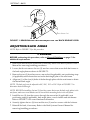
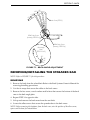
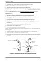
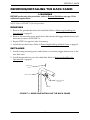


![v .] jCg _ 1l(_ `o,C..NN EinCOR `1_11E1](http://vs1.manualzilla.com/store/data/005961751_1-73960e1521729271050e00b8575619b8-150x150.png)