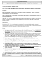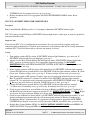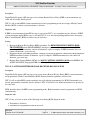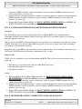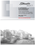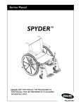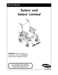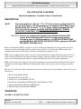
1
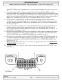
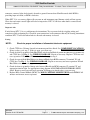
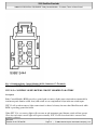
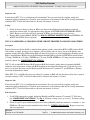
2000 Cadillac Escalade
2000 ACCESSORIES & EQUIPMENT' 'Body Control Modules - Escalade, Tahoe & Yukon Denali
2000 ACCESSORIES & EQUIPMENT
Body Control Modules - Escalade, Tahoe & Yukon Denali
DESCRIPTION
NOTE:
This article applies to "old style" "C" & "K" Series vehicles equipped with 5.7L,
6.5L and 7.4L engines. Old style pickups are not equipped with a Body Control
Module (BCM). For "new style" "C" & "K" Series vehicles equipped with 4.3L,
4.8L, 5.3L and 6.0L engines, see BODY CONTROL MODULES -- SIERRA,
SILVERADO, SUBURBAN, TAHOE, YUKON & YUKON XL article.
WARNING: Vehicles are equipped with Supplemental Inflatable Restraint (SIR)
system. Before attempting ANY repairs involving steering column,
instrument panel or related components, see SERVICE PRECAUTIONS
and DISABLING & ACTIVATING AIR BAG SYSTEM in appropriate AIR BAG
RESTRAINT SYSTEMS article.
Body Control Module (BCM) is designed to process various input information it receives from sensors and
switches or borrows from other vehicle systems connected to class 2 serial data line. BCM evaluates this
information and controls certain body systems by commanding an output on or off.
BCM can also command other vehicle systems to control functions by sending specific messages over class 2
serial data line. BCM controls operation of audible warnings, indicator warnings, power door locks, remote
keyless entry, Passlock(tm) theft deterrent, content theft deterrent, interior and exterior illumination.
BCM goes into low power mode (asleep state) when ignition has been turned off and 20 minutes have elapsed
without any wake up signals. BCM goes into high power mode (wake up state) after receiving any wake up
signals.
The class 2 serial data line allows communication between modules and scan tool. Modules on the class 2 serial
data line are:
Body Control Module (BCM).
Instrument Panel Cluster (IPC).
Transfer Case Control Module (TCCM).
Powertrain Control Module (PCM)/Vehicle Control Module (VCM).
Supplemental Inflatable Restraint (SIR) Module.
Electronic Brake Control Module (EBCM).
OPERATION
ASLEEP & AWAKE FUNCTIONS
Microsoft
October-22-10 7:55:24
7:55:08 PM
Page 1
© 2005 Mitchell Repair Information Company, LLC.
2000 Cadillac Escalade
2000 ACCESSORIES & EQUIPMENT' 'Body Control Modules - Escalade, Tahoe & Yukon Denali
After ignition switch is turned off and 20 minutes elapse without any wake up signals, Body Control Module
(BCM) enters an asleep state and goes into low power mode. Wake up signals turn BCM on to begin controlling
and/or monitoring of certain functions. BCM wake-up inputs are as follows:
Dome light.
Door ajar switches.
Door handle switches.
Ignition key put into ignition switch.
Ignition key removed from ignition switch.
Interior light request active.
Ignition turned on.
Key in door lock switch.
Liftgate jamb switch
Liftgate release switch.
Parking lights.
Power door lock switches.
Remote transmitter request to BCM.
AUDIBLE WARNINGS (CHIME)
When BCM determines a driver warning chime is needed, BCM will sound chime when applicable.
BATTERY RUNDOWN PROTECTION
BCM helps to prevent inadvertent battery rundown from situations such as courtesy lights left on. BCM will
turn off courtesy light circuit after ignition has been off for 20 minutes and no light request input has been
received.
DOOR LOCK/UNLOCK SWITCH FUNCTION
Driver's and passenger's door lock/unlock switches are inputs to BCM. BCM will command door lock relay to
unlock driver's door according to state of driver's or passenger's door lock switch.
DRIVER WARNING TELLTALES
BCM activates seat belt telltale in instrument cluster.
EXIT LIGHTING
Interior lights will illuminate for 40 seconds when ignition key is removed from ignition switch.
ILLUMINATED ENTRY
Interior lights will illuminate for 15 seconds when any door is opened and closed.
Microsoft
October-22-10 7:55:08 PM
Page 2
© 2005 Mitchell Repair Information Company, LLC.
2000 Cadillac Escalade
2000 ACCESSORIES & EQUIPMENT' 'Body Control Modules - Escalade, Tahoe & Yukon Denali
INTERIOR ILLUMINATION
Discrete input to BCM from door jamb switches or door handle or dome light inputs provide control for
courtesy lights, illuminated entry control of courtesy lights, vanity mirror light, dome lights, glove box lights
and reading lights. BCM can turn on some of interior lighting independently of interior lighting system.
LIFTGATE RELEASE FUNCTION
Liftgate release switch is an input to BCM. If liftgate release switch is pressed, BCM will energize liftgate
release relay and command liftgate to release if shift lever is in Park or Neutral or parking brake conditions are
met.
LOCKOUT PREVENTION
Lockout prevention feature is activated when key is in ignition switch, any door is opened and power door lock
is pressed. This feature will lock all doors, then unlock driver's door.
POWER DOOR LOCK/UNLOCK FUNCTION
BCM is responsible for energizing door lock relay. Door lock relay will be energized whenever BCM receives a
command from any door lock/unlock switch or remote transmitter.
REMOTE ILLUMINATED ENTRY
Interior lights will illuminate for 40 seconds when unlock button or liftgate release button is pressed on
transmitter. Interior lights will illuminate for 2 seconds when lock button is pressed on transmitter.
RETAINED ACCESSORY POWER
Retained Accessory Power (RAP) feature allows power windows, radio and front and rear wiper systems to be
operated after ignition is turned from on to off. Power will be turned off when any door is opened or 10 minutes
has elapsed.
COMPONENT LOCATIONS
COMPONENT LOCATIONS
Component
Body Control Module (BCM)
Data Link Connector (DLC)
Electronic Brake Control Module (EBCM)
Electronic Variable Orifice (EVO)/Passlock
Control Module
Instrument Panel Fuse Block
Powertrain Control Module (PCM)
Location
In Center Console
Under Left Side Of Instrument Panel, Near Steering
Column
Near Brake Master Cylinder
Under Center Of Instrument Panel
Behind Left End Of Instrument Panel
Behind Glove Box, Under Right Side Of Instrument
Microsoft
October-22-10 7:55:08 PM
Page 3
© 2005 Mitchell Repair Information Company, LLC.
2000 Cadillac Escalade
2000 ACCESSORIES & EQUIPMENT' 'Body Control Modules - Escalade, Tahoe & Yukon Denali
Remote Control Door Lock Receiver
Transfer Case Control Module (TCCM)
Underhood Fuse Block
Vehicle Control Module (VCM)
Vehicle Interface Unit (VIU)
Panel
On Steering Column Support Bracket
Behind Left Side Of Instrument Panel, On Steering
Column Support Bracket
Left Rear Corner Of Engine Compartment
Left Side Of Engine Compartment, On Fenderwell
Under Right Rear Seat
PROGRAMMING
REMOTE KEYLESS ENTRY (RKE) TRANSMITTER
CAUTION: If vehicle is equipped with radio anti-theft feature (THEFTLOCK(R)), obtain
secret code from customer prior to disconnecting power to vehicle or
removing RADIO fuse.
NOTE:
Programming of RKE transmitters can not be done simultaneously. First RKE
transmitter must be programmed completely before programming next RKE
transmitter(s). A maximum of 4 RKE transmitters may be programmed into BCM
memory.
1. Turn ignition switch to RUN position to deactivate Content Theft Deterrent (CTD) alarm system (if
equipped). Turn ignition switch to OFF position. Remove RADIO fuse (25-amp) from instrument panel
fuse block.
NOTE:
While programming transmitters, wait for doors to unlock. Failure to do
this, will cancel programming.
2. Cycle ignition switch from OFF to RUN position 3 times within 5 seconds, leaving ignition switch in ON
position. Body Control Module (BCM) will indicate programming sequence is active by activating hatch
release, locking doors, then unlocking doors.
3. Press and hold both LOCK and UNLOCK buttons on RKE transmitter to be programmed for 15 seconds.
Doors will lock and unlock, and hatch release will activate to verify RKE transmitter has been recognized
by BCM.
4. Repeat step 3 for remaining RKE transmitters. After programming RKE transmitter(s), reinstall RADIO
fuse. Turn ignition switch to OFF position.
SELF-DIAGNOSTIC SYSTEM
NOTE:
If vehicle is equipped with THEFTLOCK(R) anti-theft device, obtain code from
customer prior to disconnecting power to vehicle. See owner's manual for
proper THEFTLOCK(R) procedures.
Microsoft
October-22-10 7:55:08 PM
Page 4
© 2005 Mitchell Repair Information Company, LLC.
2000 Cadillac Escalade
2000 ACCESSORIES & EQUIPMENT' 'Body Control Modules - Escalade, Tahoe & Yukon Denali
Body Control Module (BCM) is equipped with a self-diagnostic system which detects system failures or
abnormalities. When a malfunction occurs, BCM will store a numerical code. Malfunctions are recorded as
history or current failures. Intermittent failures may be caused by problems with electrical circuit. If a visual
inspection does not locate problem, vehicle may be driven with a DVOM attached to suspect circuit. Abnormal
voltage or resistance readings when problem occurs indicates problem is within that circuit. However, a
damaged Electronic Variable Orifice (EVO)/Passlock module can occasionally be the cause.
RETRIEVING DIAGNOSTIC TROUBLE CODES
NOTE:
DTCs 41-45 will only set while in Body Control Module (BCM) diagnostic mode
and a button on remote keyless entry system transmitter is pressed. Codes are
used to determine performance of Remote Keyless Entry (RKE) system
transmitter and receiver in BCM.
1. Turn ignition switch to RUN position to disarm theft deterrent system (if equipped). Turn ignition switch
to OFF position. Remove RADIO fuse No. 17 (25-amp) from instrument panel fuse block. See
COMPONENT LOCATIONS .
2. Turn ignition switch to ACC position. Chime will sound 2 times to verify system has entered
programming mode for customizing special features. Within 5 seconds, turn ignition switch to OFF
position, then back to ACC position. Chime will sound 3 times to verify diagnostic mode has now been
entered.
3. BCM will begin to flash codes on SECURITY indicator light 4 seconds after entering diagnostic mode.
Each flash of indicator represents a number (i.e., one flash followed by 2 quick flashes represents DTC
12). DTC 12 will always be the first code displayed, indicating diagnostic mode is at beginning of code
display. Last code to be displayed will be DTC 55 followed by hardware configuration, then software
configuration. Each code is displayed 3 times before next code is displayed.
4. If more than one code is present, codes will display in numerical order. Codes will cycle sequentially
until diagnostic mode is exited.
BCM DTC DEFINITIONS
DTC
12
21/31
22/32
23/33
24/34
25/35
41(1)
Description
Diagnostic System Check
Courtesy Lights Feed Circuit Shorted To Ground
Courtesy Lights Return Circuit Shorted To Battery
Retained Accessory Power (RAP) Circuit Shorted To Ground Or Battery
Fasten Seat Belt Indicator Circuit Shorted To Ground Or Battery
SECURITY Indicator Light Status
Last Transmitter Message Received Valid
42(1)
Last Transmitter Message Received Invalid
43(1)
Last Transmitter Message Received Had Sumcheck Error
44(1)
Last Transmitter Message Received Had Encryption Error
45(1)
55
Receiver Processing Currently In 20-Second Lock-Out
Begin Configuration Display
Microsoft
October-22-10 7:55:08 PM
Page 5
© 2005 Mitchell Repair Information Company, LLC.
2000 Cadillac Escalade
2000 ACCESSORIES & EQUIPMENT' 'Body Control Modules - Escalade, Tahoe & Yukon Denali
U1300
Class 2 Data Link Low
U1301
Class 2 Data Link High
U1XXX
Loss Of XXX Communication
(1) This is a Remote Keyless Entry (RKE) system code only. Codes are automatically cleared after they
are displayed. To display codes again, a transmitter button must be pushed again.
INPUT/OUTPUT DIAGNOSTICS
While in diagnostic mode, if certain Body Control Module (BCM) inputs are activated or deactivated, BCM
will respond with various indicators. For example, if a door lock switch is pressed, or if door or rear
compartment lid is opened or closed, BCM will flash fasten seat belt indicator light and will sound an audible
warning tone. BCM will also attempt to perform operation normally performed by that switch transition.
BCM also responds to changes in shock sensor or tamper input. Tamper input is activated by minor blows to
vehicle, and shock input is activated by heavy blows to vehicle. Shock input can be activated by tapping on
shock sensor located behind right rear wheelwell. If either input is activated, BCM will cause horns to chirp and
will sound an audible warning tone.
If interior light switch is activated or deactivated while BCM is in diagnostic mode, BCM will flash fasten seat
belt indicator light, sound an audible warning tone and flash courtesy lights. On vehicles equipped with
Universal Theft Deterrent (UTD), at each interior light switch transition, BCM will cause courtesy lights to
flash, horns to chirp and exterior lights to flash.
CLEARING DIAGNOSTIC TROUBLE CODES
Current Diagnostic Trouble Codes (DTCs) will remain stored and displayed as long as Body Control Module
(BCM) detects fault to be current in diagnostic mode. History DTCs will remain stored by BCM until cleared.
Current DTCs (codes 21-24) and history DTCs (codes 31-34) can be cleared by depressing door unlock switch
for 4 seconds while BCM is in diagnostic mode. After 4-second time period, chime will sound 3 times to
confirm codes have cleared.
SCAN TOOL DOES NOT COMMUNICATE WITH CLASS 2 DEVICE
Description
Modules connected to class 2 serial data line monitor serial data communications during normal vehicle
operation. Operating information and commands are exchanged between modules. Connecting scan tool to Data
Link Connector (DLC) allows communication with modules for diagnostics. DTCs may be set due to this
symptom and during testing procedure. Complete testing procedure to ensure that all DTCs are diagnosed and
cleared.
Diagnostic Aids
When class 2 serial data line is shorted to ground, DTC U1300 will be set. When class 2 serial data line is
shorted to voltage, DTC U1301 will be set.
Microsoft
October-22-10 7:55:08 PM
Page 6
© 2005 Mitchell Repair Information Company, LLC.
2000 Cadillac Escalade
2000 ACCESSORIES & EQUIPMENT' 'Body Control Modules - Escalade, Tahoe & Yukon Denali
Testing
1. Disconnect scan tool from Data Link Connector (DLC). Turn ignition switch to RUN position. Connect
DVOM between DLC connector terminals No. 2 (Purple wire) and 4 (Black wire). See Fig. 1 . If 7 volts
or more exists, go to next step. If less than 7 volts exists, go to step 9 .
2. Turn ignition switch to OFF position. Disconnect Light Gray 36-pin engine-to-instrument panel harness
connector, located in left rear corner of engine compartment. Turn ignition switch to RUN position.
Observe voltage reading with DVOM still connected between DLC connector terminals No. 2 (Purple
wire) and 4 (Black wire). If 7 volts or more exists, go to step 5 . If less than 7 volts exists, go to next step.
3. Turn ignition switch to OFF position. Reconnect Light Gray 36-pin engine-to-instrument panel harness
connector. Disconnect Black 10-pin Electronic Brake Control Module (EBCM) connector, located in left
rear corner of engine compartment near master cylinder. Turn ignition switch to RUN position. Observe
voltage reading with DVOM still connected between DLC connector terminals No. 2 (Purple wire) and 4
(Black wire). If 7 volts or more exists, go to next step. If less than 7 volts exists, go to step 17 .
4. Turn ignition switch to OFF position. On models equipped with diesel engine, disconnect Powertrain
Control Module (PCM) connectors located under right side of instrument panel behind glove box. On
models equipped with gasoline engine, disconnect Vehicle Control Module (VCM) connectors located
underhood on left inner fenderwell. On all models, turn ignition switch to RUN position. Observe voltage
reading with DVOM still connected between DLC connector terminals No. 2 (Purple wire) and 4 (Black
wire). If 7 volts or more exists, go to step 7 . If less than 7 volts exists, go to step 17 .
5. Turn ignition switch to OFF position. Disconnect Green 16-pin Electronic Variable Orifice/Passlock
(EVO/Passlock) module connector, located under center of instrument panel. Turn ignition switch to
RUN position. Observe voltage reading with DVOM still connected between DLC connector terminals
No. 2 (Purple wire) and 4 (Black wire). If 7 volts or more exists, go to next step. If less than 7 volts exists,
go to step 17 .
6. Turn ignition switch to OFF position. Disconnect Natural 32-pin Transfer Case Control Module (TCCM)
connector, located behind left side of instrument panel on steering column support bracket. Turn ignition
switch to RUN position. Observe voltage reading with DVOM still connected between DLC connector
terminals No. 2 (Purple wire) and 4 (Black wire). If 7 volts or more exists, go to step 8 . If less than 7
volts exists, go to step 17 .
7. Repair short to voltage in Purple wire between PCM (diesel) or VCM (gasoline), EBCM and Light Gray
36-pin engine-to-instrument panel harness connector. See appropriate wiring diagram in DATA LINK
CONNECTORS article in WIRING DIAGRAMS. After repairs, go to step 18 .
8. Repair short to voltage in Purple wire between DLC, EVO/Passlock module, TCCM and Light Gray 36pin engine-to-instrument panel harness connector. See appropriate wiring diagram in DATA LINK
CONNECTORS article in WIRING DIAGRAMS. After repairs, go to step 18 .
9. Turn ignition switch to OFF position. Connect DVOM between ground and DLC connector terminal No.
2 (Purple wire). If continuity exists, go to next step. If continuity does not exist, go to step 18 .
10. Disconnect Light Gray 36-pin engine-to-instrument panel harness connector, located in left rear corner of
engine compartment. Observe reading with DVOM still connected between ground and DLC connector
terminal No. 2 (Purple wire). If continuity exists, go to step 13 . If continuity does not exist, go to next
step.
11. Reconnect Light Gray 36-pin engine-to-instrument panel harness connector. Disconnect Black 10-pin
Electronic Brake Control Module (EBCM) connector, located in left rear corner of engine compartment
near master cylinder. Observe reading with DVOM still connected between ground and DLC connector
Microsoft
October-22-10 7:55:08 PM
Page 7
© 2005 Mitchell Repair Information Company, LLC.
2000 Cadillac Escalade
2000 ACCESSORIES & EQUIPMENT' 'Body Control Modules - Escalade, Tahoe & Yukon Denali
12.
13.
14.
15.
16.
17.
18.
terminal No. 2 (Purple wire). If continuity exists, go to next step. If continuity does not exist, go to step
17 .
On models equipped with diesel engine, disconnect Powertrain Control Module (PCM) connectors
located under right side of instrument panel behind glove box. On models equipped with gasoline engine,
disconnect Vehicle Control Module (VCM) connectors located underhood on left inner fenderwell. On all
models, observe reading with DVOM still connected between ground and DLC connector terminal No. 2
(Purple wire). If continuity exists, go to step 15 . If continuity does not exist, go to step 17 .
Disconnect Green 16-pin Electronic Variable Orifice/Passlock (EVO/Passlock) module connector,
located under center of instrument panel. Observe reading with DVOM still connected between ground
and DLC connector terminal No. 2 (Purple wire). If continuity exists, go to next step. If continuity does
not exist, go to step 17 .
Disconnect Natural 32-pin Transfer Case Control Module (TCCM) connector, located under left side of
instrument panel on steering column support bracket. Observe reading with DVOM still connected
between ground and DLC connector terminal No. 2 (Purple wire). If continuity exists, go to step 16 . If
continuity does not exist, go to step 17 .
Repair short to ground in Purple wire between and Light Gray 36-pin engine-to-instrument panel harness
connector, located in left rear corner of engine compartment. See appropriate wiring diagram in DATA
LINK CONNECTORS article in WIRING DIAGRAMS. After repairs, go to step 18 .
Repair short to ground in Purple wire between DLC, EVO/Passlock module, TCCM and Light Gray 36pin engine-to-instrument panel harness connector, located in left rear corner of engine compartment. See
appropriate wiring diagram in DATA LINK CONNECTORS article in WIRING DIAGRAMS. After
repairs, go to step 18 .
Replace the last control module that was disconnected. See appropriate procedure under REMOVAL &
INSTALLATION . Go to next step.
Clear DTCs using scan tool. Operate vehicle under conditions for running specific DTC. If DTC resets,
go to step 1 .
Microsoft
October-22-10 7:55:08 PM
Page 8
© 2005 Mitchell Repair Information Company, LLC.
2000 Cadillac Escalade
2000 ACCESSORIES & EQUIPMENT' 'Body Control Modules - Escalade, Tahoe & Yukon Denali
Fig. 1: Identifying Data Link Connector (DLC) Terminals
Courtesy of GENERAL MOTORS CORP.
SCAN TOOL DOES NOT POWER UP
1. Using DVOM connected to ground, backprobe Data Link Connector (DLC) terminal No. 16 (Orange
wire). See Fig. 1 . If battery voltage exists, go to next step. If battery voltage does not exist, repair open or
short to ground in Orange wire between DLC terminal No. 16 and AUX PWR fuse (25-amp) located in
instrument panel fuse block. See appropriate wiring diagram in DATA LINK CONNECTORS article in
WIRING DIAGRAMS.
2. Using DVOM connected to ground, backprobe DLC terminal No. 4 (Black wire). If continuity exists, go
to next step. If continuity does not exist, repair open or short to voltage in Black wire between DLC
terminal No. 4 and ground connection behind left side of instrument panel below instrument panel fuse
block. See appropriate wiring diagram in DATA LINK CONNECTORS article in WIRING
DIAGRAMS.
3. Check for poor connections between scan tool and DLC terminals No. 4 and 16. Repair as necessary. If
DLC connections check okay, go to next step.
4. Scan tool may be malfunctioning. Check scan tool manual for diagnostic procedures. If necessary,
substitute a known-good scan tool.
DIAGNOSTIC TESTS
NOTE:
If vehicle is equipped with THEFTLOCK(R) anti-theft device, obtain code from
customer prior to disconnecting power to vehicle. See owner's manual for
proper THEFTLOCK(R) procedures.
DTC 12: DIAGNOSTIC SYSTEM CHECK
Description
DTC 12 is always displayed as the first code, indicating diagnostic display is in progress. If DTCs do not
display, go to Testing . If DTCs display, go to appropriate diagnostic procedure. See BCM DTC
DEFINITIONS table under SELF-DIAGNOSTIC SYSTEM.
Testing
1. Turn ignition switch to RUN position. If SECURITY indicator light illuminates, go to next step. If
SECURITY indicator light does not illuminate, go to step 3 .
2. Attempt to enter Body Control Module (BCM) diagnostic mode. If SECURITY indicator light flashes
DTCs, system is operating properly. Go to appropriate diagnostic procedure. See BCM DTC
DEFINITIONS table under SELF-DIAGNOSTIC SYSTEM. If SECURITY indicator light does not
flash DTCs, go to next step.
3. Disconnect Red 2-pin SECURITY indicator light connector. Connect DVOM between ground and Red 2pin SECURITY indicator light connector terminal "B" (Dark Green wire). If battery voltage exists with
ignition on, go to step 5 . If battery voltage does not exist with ignition on, go to next step.
Microsoft
October-22-10 7:55:08 PM
Page 9
© 2005 Mitchell Repair Information Company, LLC.
2000 Cadillac Escalade
2000 ACCESSORIES & EQUIPMENT' 'Body Control Modules - Escalade, Tahoe & Yukon Denali
4. Turn ignition switch to OFF position. Check for open or poor connection in Dark Green wire between
Blue 32-pin BCM connector C1 terminal C16 and Red 2-pin SECURITY indicator light connector
terminal "B". See Fig. 2 . See WIRING DIAGRAMS . Repair as necessary and retest operation. If Dark
Green wire is okay, go to step 8 .
5. Connect DVOM between ground and Red 2-pin SECURITY indicator light connector terminal
"A" (Black wire). If continuity exists, go to next step. If continuity does not exist, go to step 7 .
6. Check for open or poor connection in Black wire between Black 6-pin BCM connector C2 terminal "A"
and ground. See WIRING DIAGRAMS . Repair as necessary and retest operation. If Black wire is okay,
go to step 8 .
7. Check for open or poor connection in Black wire between Red 2-pin SECURITY indicator light
connector terminal "A" and ground connection located under right side of instrument panel mounted to
Heating Ventilation Air Conditioning (HVAC) plenum bracket. See appropriate wiring diagram in ANTITHEFT SYSTEMS article. Repair as necessary and retest operation. If Black wire is okay, go to next
step.
8. Replace Body Control Module (BCM). See BODY CONTROL MODULE (BCM) under REMOVAL
& INSTALLATION. Retest operation.
Fig. 2: Identifying Body Control Module (BCM) Connector C1 Terminals
Courtesy of GENERAL MOTORS CORP.
DTC 21/31: COURTESY LIGHTS FEED CIRCUIT SHORTED TO GROUND
Description
Body Control Module (BCM) provides a 12-volt output to courtesy lights feed circuit when commanded by
instrument panel dimmer switch, door jamb switch or rear compartment lid ajar indicator switch inputs.
DTC 21 will set when battery circuit is open due to a problem with COURTESY fuse No. 8, faulty harness or
Microsoft
October-22-10 7:55:08 PM
Page 10
© 2005 Mitchell Repair Information Company, LLC.
2000 Cadillac Escalade
2000 ACCESSORIES & EQUIPMENT' 'Body Control Modules - Escalade, Tahoe & Yukon Denali
connector, courtesy lights feed circuit is shorted to ground for more than 50 milliseconds while BCM is
providing input on circuit, or BCM is defective.
When DTC 21 is set, courtesy lights will not come on and instrument panel dimmer switch will not operate.
Glove box and center console lights will also be inoperative. DTC 21 will clear when fault is corrected and
memory is cleared.
Diagnostic Aids
If only history DTC 31 is set, problem may be intermittent. Try to recreate fault by wiggling wiring and
connectors while performing test. Check for poor connections at all connectors that may be causing intermittent
condition. DTC 31 will clear when fault is corrected and memory is cleared.
Testing
NOTE:
Check for proper installation of aftermarket electronic equipment.
1. Check CTSY fuse (20-amp) located in instrument panel fuse block. See COMPONENT LOCATIONS .
If fuse is okay, go to step 3 . If fuse is open, go to next step.
2. Check for short to ground in Dark Blue/White wire between Black 6-pin BCM connector C2 terminal "B"
and CTSY fuse. See Fig. 3 . See WIRING DIAGRAMS . Repair as necessary. Replace CTSY fuse and
retest operation. If Dark Blue/White wire checks okay, go to step 4 .
3. Check for open in Dark Blue/White wire between Black 6-pin BCM connector C2 terminal "B" and
CTSY fuse. See Fig. 3 . See WIRING DIAGRAMS . Repair as necessary and retest operation. If Dark
Blue/White wire checks okay, go to next step.
4. Check for short to ground in Orange wire between Black 6-pin BCM connector C2 terminal "E" and
appropriate interior light. See appropriate wiring diagram in ILLUMINATION/INTERIOR LIGHTS
article. Repair as necessary and retest operation. If Orange wire checks okay, go to next step.
5. Replace Body Control Module (BCM). See BODY CONTROL MODULE (BCM) under REMOVAL
& INSTALLATION. Retest operation.
Microsoft
October-22-10 7:55:08 PM
Page 11
© 2005 Mitchell Repair Information Company, LLC.
2000 Cadillac Escalade
2000 ACCESSORIES & EQUIPMENT' 'Body Control Modules - Escalade, Tahoe & Yukon Denali
Fig. 3: Identifying Body Control Module (BCM) Connector C2 Terminals
Courtesy of GENERAL MOTORS CORP.
DTC 22/32: COURTESY LIGHTS RETURN CIRCUIT SHORTED TO BATTERY
Description
Body Control Module (BCM) provides a ground path on courtesy lights return circuit when commanded by
instrument panel dimmer switch, door jamb switch or rear compartment lid ajar indicator switch inputs.
DTC 22 will set when courtesy lights return circuit is shorted to battery for more than 50 milliseconds while
BCM is providing ground for circuit.
When DTC 22 is set, courtesy lights will not come on and instrument panel dimmer switch will not operate.
Glove box and center console lights will operate normally. DTC 22 will clear when fault is corrected and
memory is cleared.
Microsoft
October-22-10 7:55:08 PM
Page 12
© 2005 Mitchell Repair Information Company, LLC.
2000 Cadillac Escalade
2000 ACCESSORIES & EQUIPMENT' 'Body Control Modules - Escalade, Tahoe & Yukon Denali
Diagnostic Aids
If only history DTC 32 is set, problem may be intermittent. Try to recreate fault by wiggling wiring and
connectors while performing test. Check for poor connections at all connectors that may be causing intermittent
condition. DTC 32 will clear when fault is corrected and memory is cleared.
Testing
1. Check for short to battery voltage in White wire between headlight and panel dimmer switch and
appropriate interior light. See appropriate wiring diagram in ILLUMINATION/INTERIOR LIGHTS
article. Repair as necessary and retest operation. If White wire checks okay, go to next step.
2. Replace Body Control Module (BCM). See BODY CONTROL MODULE (BCM) under REMOVAL
& INSTALLATION. Retest operation.
DTC 23/33: RETAINED ACCESSORY POWER CIRCUIT SHORTED TO GROUND OR BATTERY
Description
Retained Accessory Power (RAP) is enabled when ignition switch is turned from RUN to OFF position. RAP
will continue to supply power to power windows, radio and front and rear wipers for up to 10 minutes after
ignition switch is turned to OFF position. RAP will shut off if any door is opened during this 10 minute period.
Body Control Module (BCM) provides RAP function through RAP feed circuit to PWR WDO circuit breaker
(25-amp), RADIO fuse (25-amp), WIPERS fuse (25-amp) and RR WIPER fuse (25-amp) located in instrument
panel fuse block. See COMPONENT LOCATIONS .
DTC 23 will set when BCM detects RAP output on RAP feed circuit is either shorted to ground with RAP
enabled or shorted to battery voltage with RAP disabled for more than 50 milliseconds. Code will also set if
there is an open in Red wire between Black 6-pin BCM connector C2 terminal "F" and IGNB fuse (50-amp)
located in underhood fuse block.
When DTC 23 is set, RAP will not operate (shorted to ground) or RAP will not deactivate when door is opened
(shorted to battery). DTC 23 will clear when fault is corrected and memory is cleared.
Diagnostic Aids
If only history DTC 33 is set, problem may be intermittent. Try to recreate fault by wiggling wiring and
connectors while performing test. Check for poor connections at all connectors that may be causing intermittent
condition. DTC 33 will clear when fault is corrected and memory is cleared.
RAP Inoperative
1. Use DVOM connected to ground, backprobe Black 6-pin BCM connector C2 terminal "F" (Red wire).
See COMPONENT LOCATIONS . See Fig. 3 . If battery voltage exists, go to step 3 . If battery voltage
does not exist, go to next step.
2. Check for open or poor connection in Red wire between Black 6-pin BCM connector C2 terminal "F" and
IGNB fuse (50-amp) located in underhood fuse block. See WIRING DIAGRAMS . Repair as necessary
and retest operation.
Microsoft
October-22-10 7:55:08 PM
Page 13
© 2005 Mitchell Repair Information Company, LLC.
2000 Cadillac Escalade
2000 ACCESSORIES & EQUIPMENT' 'Body Control Modules - Escalade, Tahoe & Yukon Denali
3. Gain access to Blue 56-pin in-line harness connector, located under floor console trim plate. Turn ignition
switch to RUN position, then to OFF position (RAP mode). Ensure doors stay closed so as not to exit
RAP mode. Using DVOM connected to ground, backprobe Blue 56-pin in-line harness connector
terminal B9 (Dark Blue wire). See Fig. 4 . If battery voltage exists, go to next step. If battery voltage does
not exist, go to step 5 .
4. Using DVOM connected to ground, backprobe RR WIPER fuse located in instrument panel fuse block. If
battery voltage exists, system is okay at this time. If battery voltage does not exist, go to step 7 .
5. Using DVOM connected to ground, backprobe Black 6-pin BCM connector C2 terminal "C" (Dark Blue
wire). If battery voltage exists, go to next step. If battery voltage does not exist, go to step 8 .
6. Repair open in Dark Blue wire between Black 6-pin BCM connector C2 terminal "C" and Blue 56-pin inline harness connector terminal B9. See WIRING DIAGRAMS . Retest operation.
7. Repair open in Dark Blue wire between Blue 56-pin in-line harness connector terminal B9 and CTSY
fuse. See WIRING DIAGRAMS . Retest operation.
8. Replace Body Control Module (BCM). See BODY CONTROL MODULE (BCM) under REMOVAL
& INSTALLATION. Retest operation.
RAP Inactive
1. Gain access to Blue 56-pin in-line harness connector, located under floor console trim plate. Disconnect
Blue 56-pin in-line harness connector. Using DVOM connected to ground, backprobe console-side of
Blue 56-pin in-line harness connector terminal B9. See Fig. 4 . If battery voltage exists, go to next step. If
battery voltage does not exist, go to step 3 .
2. Check for short to voltage in Dark Blue wire between Black 6-pin BCM connector C2 terminal "C" and
Blue 56-pin in-line harness connector terminal B9. See Fig. 3 . See WIRING DIAGRAMS . Repair as
necessary and retest operation. If Dark Blue wire checks okay, go to step 5 .
3. Using DVOM connected to ground, backprobe instrument panel-side of Blue 56-pin in-line harness
connector terminal B9. If battery voltage exists, go to next step. If battery voltage does not exist, system
is okay at this time.
4. Repair short to battery voltage in Dark Blue wire between Blue 56-pin in-line harness connector terminal
B9 and instrument panel fuse block. See WIRING DIAGRAMS . Retest operation.
5. Replace Body Control Module (BCM). See BODY CONTROL MODULE (BCM) under REMOVAL
& INSTALLATION. Retest operation.
Microsoft
October-22-10 7:55:08 PM
Page 14
© 2005 Mitchell Repair Information Company, LLC.
2000 Cadillac Escalade
2000 ACCESSORIES & EQUIPMENT' 'Body Control Modules - Escalade, Tahoe & Yukon Denali
Fig. 4: Identifying Blue 56-Pin In-Line Harness Connector Terminals
Microsoft
October-22-10 7:55:08 PM
Page 15
© 2005 Mitchell Repair Information Company, LLC.
2000 Cadillac Escalade
2000 ACCESSORIES & EQUIPMENT' 'Body Control Modules - Escalade, Tahoe & Yukon Denali
Courtesy of GENERAL MOTORS CORP.
DTC 24/34: FASTEN SEAT BELT INDICATOR CIRCUIT SHORTED TO GROUND OR BATTERY
Description
Body Control Module (BCM) provides a 12-volt output to fasten seat belt indicator, located on instrument
cluster, while driver's seat belt is unfastened.
DTC 24 will set when BCM detects fasten seat belt output is either shorted to ground or shorted to voltage for
more than 50 milliseconds.
When DTC 24 is set, fasten seat belt indicator will not come on when ignition is on and driver's seat belt is not
fastened, or fasten seat belt indicator is always illuminated. DTC 24 will clear when fault is corrected and
memory is cleared.
Diagnostic Aids
If only history DTC 34 is set, problem may be intermittent. Try to recreate fault by wiggling wiring and
connectors while performing test. Check for poor connections at all connectors that may be causing intermittent
condition. DTC 34 will clear when fault is corrected and memory is cleared.
Testing
1. Turn ignition switch to OFF position. Disconnect Blue 32-pin BCM connector C1. See COMPONENT
LOCATIONS . Turn ignition switch to RUN position. If fasten seat belt indicator comes on, go to step
7 . If fasten seat belt indicator does not come on, go to next step.
2. Turn ignition switch to OFF position. Reconnect Blue 32-pin BCM connector C1. Disconnect instrument
cluster connector. Connect a test light between instrument cluster connector terminals No. 30 (Yellow
wire) and No. 31 (Black/White wire). Ensure driver's seat belt is unfastened. Turn ignition switch to RUN
position. If test light illuminates, go to next step. If test light does not illuminate, go to step 4 .
3. Replace instrument cluster. See appropriate ANALOG INSTRUMENT PANELS article. Retest
operation. If symptom still exists, go to next step.
4. Turn ignition switch to OFF position. Connect test light between battery voltage and instrument cluster
connector terminal No. 30 (Yellow wire). If test light illuminates, go to next step. If test light does not
illuminate, go to step 6 .
5. Repair short to ground in Yellow wire between Blue 32-pin BCM connector C1 terminal C4 and
instrument cluster connector terminal No. 30. See Fig. 2 . See appropriate wiring diagram in WARNING
SYSTEMS article. If symptom still exists, go to next step.
6. Replace Body Control Module (BCM). See BODY CONTROL MODULE (BCM) under REMOVAL
& INSTALLATION.
7. Disconnect instrument cluster connector. Connect a test light between ground and instrument cluster
connector terminal No. 30 (Yellow wire). If test light illuminates, go to next step. If test light does not
illuminate, go to step 9 .
8. Repair short to battery voltage in Yellow wire between instrument cluster connector terminal No. 30 and
Blue 32-pin BCM connector C1 terminal C4. See Fig. 2 . See appropriate wiring diagram in WARNING
Microsoft
October-22-10 7:55:08 PM
Page 16
© 2005 Mitchell Repair Information Company, LLC.
2000 Cadillac Escalade
2000 ACCESSORIES & EQUIPMENT' 'Body Control Modules - Escalade, Tahoe & Yukon Denali
SYSTEMS article. If symptom still exists, go to next step.
9. Replace instrument cluster. See appropriate ANALOG INSTRUMENT PANELS article. Retest
operation.
DTC 25/35: SECURITY INDICATOR LIGHT STATUS
Description
Body Control Module (BCM) provides a 12-volt output to illuminate SECURITY indicator light.
DTC 25/35 will set when BCM detects SECURITY indicator light circuit is either open or shorted to ground for
more than 50 milliseconds.
Diagnostic Aids
If only history DTC 35 is set, problem may be intermittent. Try to recreate fault by wiggling wiring and
connectors while performing test. Check for poor connections at all connectors that may be causing intermittent
condition. DTC 35 will clear when fault is corrected and memory is cleared.
Testing
1. Turn ignition switch to RUN position. If SECURITY indicator light illuminates, go to next step. If
SECURITY indicator light does not illuminate, go to step 3 .
2. Attempt to enter Body Control Module (BCM) diagnostic mode. If SECURITY indicator light flashes
DTCs, system is operating properly. Go to appropriate diagnostic procedure. See BCM DTC
DEFINITIONS table under SELF-DIAGNOSTIC SYSTEM. If SECURITY indicator light does not
flash DTCs, go to next step.
3. Ensure ignition switch is in RUN position. Disconnect Red 2-pin SECURITY indicator light connector.
Connect DVOM between ground and Red 2-pin SECURITY indicator light connector terminal "B" (Dark
Green wire). If battery voltage exists, go to step 5 . If battery voltage does not exist, go to next step.
4. Turn ignition switch to OFF position. Check for open or poor connection in Dark Green wire between
Blue 32-pin BCM connector C1 terminal C16 and Red 2-pin SECURITY indicator light connector
terminal "B". See appropriate wiring diagram in appropriate ANTI-THEFT SYSTEMS article. See Fig.
2 . Repair as necessary and retest operation. If Dark Green wire is okay, go to step 8 .
5. Connect DVOM between ground and Red 2-pin SECURITY indicator light connector terminal
"A" (Black wire). If continuity exists, go to next step. If continuity does not exist, go to step 7 .
6. Check for poor connection or open in Black wire between Black 6-pin BCM connector C2 terminal "A"
and Black 56-pin in-line harness connector terminal G1. See WIRING DIAGRAMS . See Fig. 5 . Repair
as necessary and retest operation. If Black wire checks okay, go to step 8 .
7. Check for open in Black wire between Red 2-pin SECURITY indicator light connector terminal "A" and
ground connection located under right side of instrument panel mounted to Heating Ventilation Air
Conditioning (HVAC) plenum bracket. See appropriate wiring diagram in appropriate ANTI-THEFT
SYSTEMS article. Repair as necessary and retest operation. If Black wire checks okay, go to next step.
8. Replace Body Control Module (BCM). See BODY CONTROL MODULE (BCM) under REMOVAL
& INSTALLATION. Reprogram RKE transmitter(s). Retest operation.
Microsoft
October-22-10 7:55:08 PM
Page 17
© 2005 Mitchell Repair Information Company, LLC.
2000 Cadillac Escalade
2000 ACCESSORIES & EQUIPMENT' 'Body Control Modules - Escalade, Tahoe & Yukon Denali
Fig. 5: Identifying Black 56-Pin In-Line Harness Connector Terminals
Courtesy of GENERAL MOTORS CORP.
DTC 41: LAST TRANSMITTER MESSAGE RECEIVED VALID
Microsoft
October-22-10 7:55:08 PM
Page 18
© 2005 Mitchell Repair Information Company, LLC.
2000 Cadillac Escalade
2000 ACCESSORIES & EQUIPMENT' 'Body Control Modules - Escalade, Tahoe & Yukon Denali
Description
Digital Radio Frequency (RF) message received from Remote Keyless Entry (RKE) system transmitter was
valid, and all security checks passed.
DTC 41 will set when RKE system transmitter has been in programming mode out of range of Body Control
Module (BCM), or when system transmitter is defective.
Diagnostic Aids
If RKE system transmitter digital RF message is sent and no DTC is set, transmitter may be defective. If RKE
system transmitter digital RF message is sent and DTC 41 is set, but corresponding function does not operate,
Body Control Module (BCM) or harness may be defective.
Testing
1. Reprogram Remote Keyless Entry (RKE) transmitter. See REMOTE KEYLESS ENTRY (RKE)
TRANSMITTER under PROGRAMMING. Attempt to perform all functions controlled by RKE
transmitter. If RKE transmitter controls all functions, repair is complete. If RKE transmitter does not
control all functions, go to next step.
2. Program a known-good RKE transmitter. Attempt to perform all functions controlled by RKE transmitter.
If RKE transmitter controls all functions, repair is complete. If RKE transmitter does not control all
functions, go to next step.
3. Replace Body Control Module (BCM). See BODY CONTROL MODULE (BCM) under REMOVAL
& INSTALLATION. Reprogram RKE transmitter(s). Retest operation.
DTC 42: LAST TRANSMITTER MESSAGE RECEIVED HAD INVALID ID
Description
Digital Radio Frequency (RF) message received was from a Remote Keyless Entry (RKE) system transmitter
not programmed to Body Control Module (BCM). Remote function capabilities will not exist.
DTC 42 will set when RKE system transmitter was used without programming it to BCM. If transmitter was
already programmed, transmitter may be defective. DTC 42 will also set if another transmitter was operated in
the same area.
BCM should be placed in RKE system programming mode. Both transmitters must be programmed to BCM
simultaneously.
Diagnostic Aids
DTC 42 may set if one or more of the following occur during BCM diagnostic mode:
Transmitter is defective.
Transmitter not programmed to BCM was used.
Microsoft
October-22-10 7:55:08 PM
Page 19
© 2005 Mitchell Repair Information Company, LLC.
2000 Cadillac Escalade
2000 ACCESSORIES & EQUIPMENT' 'Body Control Modules - Escalade, Tahoe & Yukon Denali
Another transmitter was used in the immediate area.
Testing
1. Reprogram Remote Keyless Entry (RKE) transmitter. See REMOTE KEYLESS ENTRY (RKE)
TRANSMITTER under PROGRAMMING. Attempt to perform all functions controlled by RKE
transmitter. If RKE transmitter controls all functions, repair is complete. If RKE transmitter does not
control all functions, go to next step.
2. Program a known-good RKE transmitter. Attempt to perform all functions controlled by RKE transmitter.
If RKE transmitter controls all functions, repair is complete. If RKE transmitter does not control all
functions, go to next step.
3. Replace Body Control Module (BCM). See BODY CONTROL MODULE (BCM) under REMOVAL
& INSTALLATION. Reprogram RKE transmitter(s). Retest operation.
DTC 43: LAST TRANSMITTER MESSAGE RECEIVED HAD SUMCHECK ERROR
Description
The digital RF message received was from a Remote Keyless Entry (RKE) system transmitter that is
programmed to Body Control Module (BCM), but message did not pass sumcheck security test. No remote
function capabilities will exist.
DTC 43 will set when remote keyless entry system transmitter is out of synchronization with BCM. Fault may
be caused by transmitter buttons being pressed more than 256 times while out of range of BCM. Fault may also
be caused by transmitter battery being changed and buttons being pressed more than 10 times while out of range
of BCM. Fault may also be present if digital RF message has an error due to outside noise from surrounding
environment, or if transmitter is defective.
Most likely cause is that RKE system transmitter is out of synchronization. To synchronize transmitter, press
LOCK and UNLOCK buttons on transmitter simultaneously for 5 seconds.
Diagnostic Aids
If DTC 43 is set, transmitter is out of synchronization with BCM. This can be caused by one or more of the
following:
Transmitter buttons were pressed more than 256 times while out of BCM RF signal range.
Transmitter buttons were pressed more than 10 times while out of BCM RF signal range after transmitter
battery was replaced.
Transmitter RF signal was interrupted.
Transmitter is defective.
Testing
1. Reprogram Remote Keyless Entry (RKE) transmitter. See REMOTE KEYLESS ENTRY (RKE)
TRANSMITTER under PROGRAMMING. Attempt to perform all functions controlled by RKE
Microsoft
October-22-10 7:55:08 PM
Page 20
© 2005 Mitchell Repair Information Company, LLC.
2000 Cadillac Escalade
2000 ACCESSORIES & EQUIPMENT' 'Body Control Modules - Escalade, Tahoe & Yukon Denali
transmitter. If RKE transmitter controls all functions, repair is complete. If RKE transmitter does not
control all functions, go to next step.
2. Program a known-good RKE transmitter. Attempt to perform all functions controlled by RKE transmitter.
If RKE transmitter controls all functions, repair is complete. If RKE transmitter does not control all
functions, go to next step.
3. Replace Body Control Module (BCM). See BODY CONTROL MODULE (BCM) under REMOVAL
& INSTALLATION. Reprogram RKE transmitter(s). Retest operation.
DTC 44: LAST TRANSMITTER MESSAGE RECEIVED HAD ENCRYPTION ERROR
Description
The digital RF message received was from a Remote Keyless Entry (RKE) system transmitter that is
programmed to Body Control Module (BCM), but message did not pass encryption security test. No remote
function capabilities will exist.
DTC 44 will set when RKE system transmitter has been in program or re-synchronize mode while out of range
of BCM. Fault may also be present if digital RF message has an error due to outside noise from surrounding
environment, or if transmitter is defective.
Most likely cause is that RKE system transmitter is out of synchronization. To re-synchronize transmitter, press
LOCK and UNLOCK buttons on transmitter simultaneously for 5 seconds.
Diagnostic Aids
If DTC 44 is set, transmitter is out of synchronization with BCM. This can be caused by one or more of the
following:
Transmitter was in program mode while out of BCM RF signal range.
Transmitter RF signal was interrupted.
Transmitter is defective.
Testing
1. Reprogram Remote Keyless Entry (RKE) transmitter. See REMOTE KEYLESS ENTRY (RKE)
TRANSMITTER under PROGRAMMING. Attempt to perform all functions controlled by RKE
transmitter. If RKE transmitter controls all functions, repair is complete. If RKE transmitter does not
control all functions, go to next step.
2. Program a known-good RKE transmitter. Attempt to perform all functions controlled by RKE transmitter.
If RKE transmitter controls all functions, repair is complete. If RKE transmitter does not control all
functions, go to next step.
3. Replace Body Control Module (BCM). See BODY CONTROL MODULE (BCM) under REMOVAL
& INSTALLATION. Reprogram RKE transmitter(s). Retest operation.
DTC 45: RECEIVER PROCESSING CURRENTLY IN 20-SECOND LOCK-OUT
Microsoft
October-22-10 7:55:08 PM
Page 21
© 2005 Mitchell Repair Information Company, LLC.
2000 Cadillac Escalade
2000 ACCESSORIES & EQUIPMENT' 'Body Control Modules - Escalade, Tahoe & Yukon Denali
Description
At least 50 consecutive digital RF messages were received from a Remote Keyless Entry (RKE) system
transmitter that is programmed to Body Control Module (BCM), but message did not pass encryption security
test. BCM will cease processing any RKE system transmitter digital RF messages (good or bad) for 20 seconds.
No remote function capabilities will exist.
DTC 45 will set when RKE system transmitter has been in program or re-synchronize mode while out of range
of BCM. Fault may also be present if transmitter is defective.
Most likely cause is that RKE system transmitter is out of synchronization with BCM. To re-synchronize
transmitter, press LOCK and UNLOCK buttons on transmitter simultaneously for 5 seconds.
Diagnostic Aids
If DTC 45 is set, transmitter is out of synchronization with BCM. This can be caused by one or more of the
following:
Transmitter was in program mode while out of BCM RF signal range.
Transmitter is defective.
Testing
1. Reprogram Remote Keyless Entry (RKE) transmitter. See REMOTE KEYLESS ENTRY (RKE)
TRANSMITTER under PROGRAMMING. Attempt to perform all functions controlled by RKE
transmitter. If RKE transmitter controls all functions, repair is complete. If RKE transmitter does not
control all functions, go to next step.
2. Program a known-good RKE transmitter. Attempt to perform all functions controlled by RKE transmitter.
If RKE transmitter controls all functions, repair is complete. If RKE transmitter does not control all
functions, go to next step.
3. Replace Body Control Module (BCM). See BODY CONTROL MODULE (BCM) under REMOVAL
& INSTALLATION. Retest operation.
DTC 55: BEGIN CONFIGURATION DISPLAY
Description
DTC 55 is displayed to indicate the next 2 DTCs displayed are Body Control Module (BCM) hardware and
software configurations. First number following DTC 55 is the hardware configuration. The second number is
the software configuration. DTC 55 and both configuration numbers will always be displayed. After
configuration numbers are displayed, entire DTC list will repeat beginning with DTC 12.
DTC U1300: CLASS 2 DATA LINK LOW
Description
Modules connected to the class 2 serial data line monitor for serial data communications during normal vehicle
Microsoft
October-22-10 7:55:08 PM
Page 22
© 2005 Mitchell Repair Information Company, LLC.
2000 Cadillac Escalade
2000 ACCESSORIES & EQUIPMENT' 'Body Control Modules - Escalade, Tahoe & Yukon Denali
operation. Operating information and commands are exchanged between modules. In addition, node alive (state
of health) messages are transmitted by each module on the class 2 serial data line about once every 2 seconds.
When a module detects no messages and a low voltage on the class 2 serial data line for about 3 seconds, DTC
U1300 is set, the setting of all other class 2 communication DTCs in inhibited and the module uses default
values for all parameters received on the class 2 serial data line. A current DTC U1300 will clear when a valid
class 2 message is detected on serial data line or at the end of the current ignition cycle. A history DTC U1300
can only be cleared using scan tool.
Diagnostic Aids
DTC U1300 cannot be retrieved as current. Diagnosis for current DTC U1300 is accomplished using SCAN
TOOL DOES NOT COMMUNICATE WITH CLASS 2 DEVICE under SELF-DIAGNOSTIC SYSTEM.
An intermittent condition can be caused by a short to ground on the class 2 serial data line.
DTC U1301: CLASS 2 DATA LINK HIGH
Description
Modules connected to the class 2 serial data line monitor for serial data communications during normal vehicle
operation. Operating information and commands are exchanged between modules. In addition, node alive (state
of health) messages are transmitted by each module on the class 2 serial data line about once every 2 seconds.
When a module detects no messages and a high voltage on the class 2 serial data line for about 3 seconds, DTC
U1301 is set, the setting of all other class 2 communication DTCs in inhibited and the module uses default
values for all parameters received on the class 2 serial data line. A current DTC U1301 will clear when a valid
class 2 message is detected on serial data line or at the end of the current ignition cycle. A history DTC U1301
can only be cleared using scan tool.
Diagnostic Aids
DTC U1301 cannot be retrieved as current. Diagnosis for current DTC U1300 is accomplished using SCAN
TOOL DOES NOT COMMUNICATE WITH CLASS 2 DEVICE under SELF-DIAGNOSTIC SYSTEM.
An intermittent condition can be caused by a short to voltage on the class 2 serial data line.
DTC U1XXX: LOSS OF XXX COMMUNICATION
Description
Modules connected to class 2 serial data line monitor serial data communications during normal vehicle
operation. Operating information and commands are exchanged between modules. When a module receives a
message for a critical operating parameter, the module records the identification number of the module which
sent the message for State Of Health (SOH) monitoring (node alive messages).
Once an identification number is learned by a module, it will monitor for that module's node alive message.
Each module on the class 2 serial data line which is powered and performing functions that require detection of
a communications malfunction is required to send a node alive message every 2 seconds.
Microsoft
October-22-10 7:55:08 PM
Page 23
© 2005 Mitchell Repair Information Company, LLC.
2000 Cadillac Escalade
2000 ACCESSORIES & EQUIPMENT' 'Body Control Modules - Escalade, Tahoe & Yukon Denali
When no message is detected by from a learned identification number for 5 seconds, DTC U1XXX (where
XXX is equal to the identification number) is set. Use DTC ID NUMBER table to determine which module is
not communicating.
When more than one loss of communication DTC is set in one or more modules, perform diagnosis in the
following order:
Current DTCs before history DTCs, unless otherwise indicated in testing procedure.
DTC that was reported the most times.
From lowest number DTC to highest number DTC.
DTC ID NUMBER
ID
Module
Number
016
Powertrain Control Module (PCM)/Vehicle Control Module (VCM)/Vehicle Interface Unit
(VIU)
026
Transfer Case Control Module (TCCM)
041
Electronic Brake Control Module (EBCM)
064
Body Control Module (BCM)
096
Instrument Panel Cluster (IPC)
192
Electronic Variable Orifice/Passlock (EVO/Passlock)
Testing
1. Check for open or short to ground in power circuit(s) for non-communicating module. See POWER
DISTRIBUTION article in WIRING DIAGRAMS. Repair circuit(s) as necessary and go to step 9 . If
circuit(s) are okay, go to next step.
2. Turn ignition switch to OFF position. Check for open in ground circuit(s) for non-communicating
module. See GROUND DISTRIBUTION article in WIRING DIAGRAMS. Repair circuit(s) as necessary
and go to step 9 . If circuit(s) are okay, go to next step.
3. Disconnect scan tool. Check for open in class 2 serial data line (Purple wire). See DATA LINK
CONNECTORS article in WIRING DIAGRAMS. Repair circuit as necessary and go to step 7 . If circuit
is okay, go to next step.
4. Check for open in class 2 serial data line (Purple wire) between Data Link Connector (DLC) terminal No.
2 and non-communicating module. See Fig. 1 . See DATA LINK CONNECTORS article in WIRING
DIAGRAMS. Repair circuit as necessary and go to step 7 . If circuit is okay, go to next step.
5. Check power, ground and class 2 serial data terminals at non-communicating module connector for poor
connections or terminal tension. Repair as necessary and go to step 7 . If connections check okay, go to
next step.
6. Replace non-communicating module. See appropriate procedure under REMOVAL &
INSTALLATION . Go to step 9 .
7. Connect scan tool to DLC. Turn ignition on. On scan tool, select DISPLAY DTCS function for noncommunicating module. If scan tool displays any DTCs that do not begin with a "U", perform appropriate
diagnostic system check. See appropriate article for malfunctioning system. If scan tool does not display
Microsoft
October-22-10 7:55:08 PM
Page 24
© 2005 Mitchell Repair Information Company, LLC.
2000 Cadillac Escalade
2000 ACCESSORIES & EQUIPMENT' 'Body Control Modules - Escalade, Tahoe & Yukon Denali
any DTCs or only displays DTCs beginning with a "U", go to next step.
8. Using scan tool, clear DTCs. Go to next step.
9. Select DISPLAY DTCS function for module that had a loss of communication DTC set. If scan tool
displays any DTCs that do not begin with a "U", perform appropriate diagnostic system check. See
appropriate article for malfunctioning system. If scan tool does not display any DTCs or only displays
DTCs beginning with a "U", go to next step.
10. Using scan tool, clear DTCs. Continue diagnosing and clearing DTCs until all modules have been
diagnosed and all DTCs have been cleared.
REMOVAL & INSTALLATION
TRANSFER CASE CONTROL MODULE (TCCM)
Removal & Installation
Remove lower instrument panel trim from below steering column. Remove 2 Transfer Case Control Module
(TCCM) retaining screws. Disconnect TCCM electrical connector. Remove TCCM. To install, reverse removal
procedure.
BODY CONTROL MODULE (BCM)
NOTE:
It is necessary to remove one front seat during Body Control Module (BCM)
replacement. Either seat can be removed.
Removal & Installation
1. Disconnect negative battery cable. Remove seat pedestal trim covers on one front seat. Remove seat-tofloor retaining bolts. Disconnect electrical connector(s) as necessary. Remove seat from vehicle. Remove
console trim plate retaining screws. Lift upward on rear of console trim plate and slide rearward.
Disconnect electrical connectors as necessary. Remove console trim plate.
2. Remove 4 console-to-floor retaining bolts. Disconnect instrument panel harness and cross-body harness
connectors from console. Slide console rearward and remove from vehicle. Remove amplifier mounting
screws. Disconnect amplifier electrical connector. Remove amplifier through bottom of console. Release
retaining tabs on BCM. Remove BCM. To install, slide BCM into console and snap tabs into place. To
complete installation, reverse removal procedure.
ELECTRONIC BRAKE CONTROL MODULE
Removal & Installation
See appropriate ANTI-LOCK article in BRAKES.
INFLATABLE RESTRAINT SENSING & DIAGNOSTIC MODULE (SDM)
Removal & Installation
Microsoft
October-22-10 7:55:08 PM
Page 25
© 2005 Mitchell Repair Information Company, LLC.
2000 Cadillac Escalade
2000 ACCESSORIES & EQUIPMENT' 'Body Control Modules - Escalade, Tahoe & Yukon Denali
See appropriate AIR BAG RESTRAINT SYSTEMS article.
INSTRUMENT PANEL CLUSTER
Removal & Installation
See appropriate ANALOG INSTRUMENT PANELS article.
POWERTRAIN CONTROL MODULE (PCM)/VEHICLE CONTROL MODULE (VCM)
Removal & Installation
See appropriate REMOVAL, OVERHAUL & INSTALLATION article in ENGINE PERFORMANCE.
WIRING DIAGRAMS
Microsoft
October-22-10 7:55:08 PM
Page 26
© 2005 Mitchell Repair Information Company, LLC.
2000 Cadillac Escalade
2000 ACCESSORIES & EQUIPMENT' 'Body Control Modules - Escalade, Tahoe & Yukon Denali
Microsoft
October-22-10 7:55:08 PM
Page 27
© 2005 Mitchell Repair Information Company, LLC.
2000 Cadillac Escalade
2000 ACCESSORIES & EQUIPMENT' 'Body Control Modules - Escalade, Tahoe & Yukon Denali
Fig. 6: Body Control Module (BCM) Wiring Diagram (Escalade, Tahoe & Yukon Denali)
Microsoft
October-22-10 7:55:08 PM
Page 28
© 2005 Mitchell Repair Information Company, LLC.