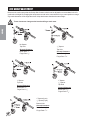
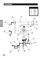
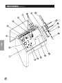
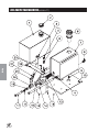
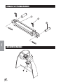
1
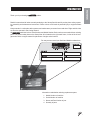
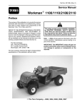
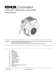
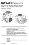
PARTS & SERVICE
MANUAL
SWEEP STAR 48
High Dump
Model 48-000-C
Starting Serial #:
GH 5003
SMITHCO PRODUCT SUPPORT
1-800-891-9435
Hwy SS and Poplar Avenue, Cameron WI 54822
E-mail: [email protected]
January, 2003
Introduction
CONTENTS
Introduction ......................................... 1-10
Service
Diagrams
Parts
Accessories
Introduction .............................................................................................. 1-3
Safe Practices ......................................................................................... 2
Specification ............................................................................................ 3
Optional Equipment ................................................................................. 3
Service .................................................................................................... 4-10
Maintenance ........................................................................................ 4-6
Service Chart ........................................................................................... 7
End User’s Service Chart ......................................................................... 8
Adjustments ............................................................................................. 9
Storage .................................................................................................... 9
Reel Height Adjustment ......................................................................... 10
Diagrams ................................................................................................ 11-15
Wiring Diagram .................................................................................12-13
Hydraulic Diagram High Lift ..............................................................14-15
Parts ....................................................................................................... 16-49
Body and Frame High Lift .................................................................16-17
Steering ............................................................................................18-19
Front Fork .........................................................................................20-21
Linkage High Lift ...............................................................................22-23
Console High Lift ..............................................................................24-25
Fuel and Oil Tank High Lift ................................................................26-27
Hydraulic Lift Cylinder .......................................................................28-29
Reel Lift Cylinder ...............................................................................30-31
Tailgate Cylinder ...............................................................................30-31
Engine and Exhaust High Lift ............................................................32-35
Electric Clutch Driven Belt Drive and Muffler ..................................... 36-37
Finger Reel High Lift .........................................................................38-39
Rear Axle High Lift ............................................................................40-41
Hopper and Tailgate High Lift ............................................................42-43
76-322 15 Series Sundstrand Pump ................................................. 44-45
48-137 Rear Wheel Motor ................................................................ 46-47
76-023 3-Bank Hydraulic Valve ........................................................48-49
Reference ...............................................................................................50-52
Notes ..................................................................................................... 50
Decal List ............................................................................................... 51
Quick Reference Replacement Parts ..................................................... 52
Warranty ....................................................................... Inside Back Cover
Reference
Thank you for purchasing a
Introduction
INTRODUCTION
product.
Read this manual and all other manuals pertaining to the Sweep Star 48 carefully as they have safety, operating, assembly and maintenance instructions. Failure to do so could result in personal injury or equipment damage.
Keep manuals in a safe place after operator and maintenance personnel have read them. Right and left sides
are from the operator’s seat, facing forward.
All
machines have a Serial Number and Model Number. Both numbers are needed when ordering
parts. The serial number plate on the Sweep Star 48 is located on the right main frame, in front of the oil and
gas tanks. Refer to engine manual for placement of engine serial number.
For easy access record your Serial and Model numbers here.
Information needed when ordering replacement parts:
1. Model Number of machine
2. Serial Number of machine
3. Name and Part Number of part
4. Quantity of parts
1
SAFE PRACTICES
Introduction
1. It is your responsibility to read this manual and all publications associated with this machine (engine,
accessories and attachments).
2. Never allow anyone to operate or service the machine or its attachments without proper training and
instructions. Never allow minors to operate any equipment.
3. Learn the proper use of the machine, the location and purpose of all the controls and gauges before you
operate the equipment. Working with unfamiliar equipment can lead to accidents.
4. Wear all the necessary protective clothing and personal safety devises to protect your head, eyes, ears,
hands and feet. Operate the machine only in daylight or in good artificial light.
5. Inspect the area where the equipment will be used. Beware of overhead obstructions and underground
obstacles. Stay alert for hidden hazards.
6. Never operate equipment that is not in perfect working order or without decals, guards, shields, or other
protective devices in place.
7. Never disconnect or bypass any switch.
8. Carbon monoxide in the exhaust fumes can be fatal when inhaled, never operate a machine without
proper ventilation.
9. Fuel is highly flammable, handle with care.
10. Keep engine clean. Allow the engine to cool before storing and always remove the ignition key.
11. After engine has started, machine must not move. If movement is evident, the neutral mechanism is not
adjusted correctly. Shut engine off and readjust so the machine does not move when in neutral position.
13. Never use your hands to search for oil leaks. Hydraulic fluid under pressure can penetrate the skin and
cause serious injury.
14. This machine demands your attention. To prevent loss of control or tipping of the vehicle:
A. Use extra caution in backing up the vehicle. Ensure area is clear.
B. Do not stop or start suddenly on any slope.
C. Reduce speed on slopes and in sharp turns. Use caution when changing directions on slopes.
D. Stay alert for holes in the terrain and other hidden hazards.
15. Before leaving operator’s position for any reason:
A. Disengage all drives.
B. Lower all attachments to the ground.
C. Set park brake.
D. Shut engine off and remove the ignition key.
16. Keep hands, feet and clothing away from moving parts. Wait for all movement to stop before you clean,
adjust or service the machine.
17. Keep the area of operation clear of all bystanders.
18. Never carry passengers.
19. Stop engine before making repairs/adjustments or checking/adding oil to the crankcase.
20. Use parts and materials supplied by SMITHCO only. Do not modify any function or part.
21. Do not remove the radiator cap when the engine is hot. When cooled, loosen cap slightly to the stop to
relieve any pressure before removing the cap completely.
These machines are intended for professional maintenance on golf courses, sports turf, and any other
area maintained turf and related trails, paths and lots. No guaranty as to the suitability for any task is
expressed or implied.
2
WEIGHTS AND DIMENSIONS
Length
Width
Height with Hopper Down
Height with Hopper Up
Wheel Base
Weight
HIGH LIFT
121" (307 cm)
60" (153 cm)
63" (160 cm)
126" (320 cm)
70" (179 cm)
1800 lbs(818 kg)
SOUND LEVEL (DBA)
At ear level
At 3 ft (0.914 m)
At 30 ft (9.14 m)
90 dba
91 dba
76 dba
ENGINE
Make
Model#
Type / Spec#
Horsepower
Fuel
Cooling System
Lubrication System
Alternator
WHEELS & TIRE
Introduction
SPECIFICATIONS FOR SWEEP STAR 48 HIGH LIFT
Kohler
CH25
CH730-0100
25 Hp (18.6 kw)
Unleaded 87 Octane
Gasoline Minimum
Air Cooled
Full Pressure
15 Amp
Front: One 18 x 9.50 x 8 Multi-rib
Rear: Two 23 x 10.50 x 12 NHS (20 psi max)
Castor: 9 x 3.50 - 4
BRAKES
Dynamic Through Hydrostat
PARK BRAKE
Hand Operated Lever, Discs on Rear Axle
SPEED
Forward Speed
Reverse Speed
0 to10 mph (0-16kph)
0 to 4 mph (0-6 kph)
BATTERY
Cold Cranking Amps
Ground Terminal Polarity
Maximum Length
Maximum Width
Maximum Height
12 Volt Automotive IBS type 45-50
48 minimum
Negative (-)
9" (23cm)
5.38" (14cm)
9" (23cm)
FLUID CAPACITY
Crankcase Oil
Fuel
Hydraulic Fluid
Grade of Hydraulic Fluid
See Engine Manual
5 gallon (19 liters)
5 gallon (19 liters)
SAE 10W-40 API Service SG Motor Oil
OPTIONAL EQUIPMENT
48-084
48" Brush Reel Kit (includes pillow blocks and pulley drive)
48-085
48" Finger Reel Kit (includes pillow blocks and pulley drive)
48-120
Dust and Filtration pack - High lift
48-121
Dust and Filtration Pack - Ground Dump
3
MAINTENANCE
Before servicing or making adjustments to machine, stop engine and remove key from
ignition.
Use all procedures and parts prescribed by the manufacturer's. Read the engine
manual.
Service
LUBRICATION
Use No. 2 General Purpose Lithium Base Grease and lubricate every 100 hours. The Sweep Star 48 has eleven
grease fittings.
One on the top of each tower. (High Lift Only)
One on the center of park brake relay on rear axle.
One on hydrostatic pedal under the floorboard.
One on the pillow block bearing on each end of finger/brush reel.
One on castor wheel mount bracket.
One on reel clutch relay.
One on reel clutch belt tightener.
One on rod end of the tailgate cylinder. (High Lift Only)
Every 500 hours of operation, separate the hydrostatic pump from the engine, clean the splined areas and lightly
grease the male portion of the pump spline. Use either Dow Corning® G-N Metal Assembly Paste or #77 Assembly Paste (Kohler # 25 357 12-s).
As you remount the pump to the engine, be certain the mating surfaces are clean and free of any foreign material, and that the pump is correctly aligned.
HYDRAULIC OIL
1. Use SAE 10W-40 API Service SG motor oil.
2. For proper warranty, change oil every 500 hours or annually, which ever is first and change the filter after
the first 20 hours, then at 100 hours, then every 250 hours thereafter.
3. The oil level should be 2" to 21/2" (5 - 6.4 cm) from top of fill neck when fluid is cold. Do not overfill.
4. After changing oil and/or filter, run the machine for a few minutes. Check oil level and for leaks.
5. Always use caution when filling hydraulic oil tank or checking level to keep system free of contaminants.
Check and service more frequently when operating in extremely cold, hot or dusty conditions.
6. If natural color of fluid is now black or smells burnt, it is possible that an overheating problem exists.
7. If fluid becomes milky, water contamination may be a problem.
8. If either of the above conditions happen, change oil and filter immediately after fluid is cool and find
cause. Take fluid level readings when system is cold.
9. In extreme temperatures you can use straight weight oil. We recommend SAE 30W API Service SG
when hot (above 90°F (33°C)) and SAE 10W API Service SG when cold (below 32°F (0°C)) ambient
temperature. Use either motor oil or hydraulic oil, but do not mix.
10. Oil being added to the system must be the same as what is already in the tank. Mark tank fill area as to
which type you put in.
4
MAINTENANCE (CONTINUED)
TIRE PRESSURE
Caution must be used when inflating a low tire to recommended pressure. Over inflating can cause tires to
explode. Front and rear tires and castor wheel should be 20 psi (1.4bar) maximum. Improper inflation will reduce tire life considerably.
WHEEL MOUNTING PROCEDURE
REAR WHEELS
1. Set park brake. Turn machine off and remove key.
Service
2. Block one of the other wheels.
3. Loosen nuts slightly on wheel to be removed.
4. Jack up machine being careful not to damage underside of machine.
5. Remove nuts, remove wheel.
5. Place new wheel on hub lining up bolt holes.
6. Torque nuts to 64-74 ft/lb (87-100Nm) using a cross pattern. Retorque after first 10 hours and every 200
hours thereafter.
7. Lower machine to ground and remove blocks and jack.
FRONT WHEEL
1. Set park brake. Turn machine off and remove key.
2. Block one of the other wheels.
3. Remove cotter pins from each end of the axle.
4. Remove axle nuts, machine bushings and axle locks.
5. Jack up front of machine being careful not to damage underside of machine.
6. Wheel and axle will come out of slots in the u-bracket, pull wheel forward.
7. Place new wheel on hub lining up bolt holes.
8. Torque nuts to 64-74 ft/lb (87-100Nm) using a cross pattern. Retorque after first 10 hours and every 200
hours thereafter.
9. Place wheel back on front fork. Tighten all bolts.
10. Lower machine to ground and remove blocks and jack.
ENGINE OIL
Change and add oil according to charts below. Do not overfill. Use a high quality detergent oil. For Kohler
engine use oil classified “For Service SG or SH”.
SAE Viscosity Grades CH25
Starting Temperature Range Anticipated Before Next Oil Change
5
MAINTENANCE (CONTINUED)
BATTERY
Batteries normally produce explosive gases which can cause personal injury. Do not allow flames, sparks or
any ignited object to come near the battery. When charging or working near battery, always shield your eyes
and always provide proper ventilation.
Battery cable should be disconnected before using “Fast Charge”.
Charge battery at 15 amps for 10 minutes or 7 amps for 30 minutes. Do not exceed the recommended charging rate. If electrolyte starts boiling over, decrease charging.
Always remove grounded (-) battery clamp first and replace it last. Avoid hazards by:
Service
1. Filling batteries in well-ventilated areas.
2. Wear eye protection and rubber gloves.
3. Avoid breathing fumes when electrolyte is added.
4. Avoid spilling or dripping electrolyte.
Battery Electrolyte is an acidic solution and should be handled with care. If electrolyte is
splashed on any part of your body, flush all contact areas immediately with liberal amounts
of water. Get medical attention immediately.
JUMP STARTING
Use of booster battery and jumper cables. Particular care should be used when connecting a
booster battery. Use proper polarity in order to prevent sparks.
To jump start (negative grounded battery):
1. Shield eyes.
2. Connect ends of one cable to positive (+) terminals of
each battery, first (A) then (B).
3. Connect one end of other cable to negative (-) terminal
of "good" battery (C).
4. Connect other end of cable (D) to engine block on unit
being started (NOT to negative (-) terminal of battery)
To prevent damage to other electrical components on unit being started, make certain that engine is at idle
speed before disconnecting jumper cables.
TOWING
When it is necessary to move the Sweep Star 48 without engine running, the bypass valve built into hydrostatic
pump must be “open” by turning it counterclockwise. An “open” valve allows fluid to pass through the wheels
freely. When normal, driven, operation is desired, valve should be closed by turning it clockwise. Failure to
“close” the valve with engine running means no power to wheels. Tow slowly. 2 m.p.h. or less.
The bypass valve is a 3/8 diameter shaft with a 11/64 hole for inserting something for leverage so you can turn it. On
the high lift it is on the top of the hydrostatic. On the ground level dump it is on the bottom of the hydrostatic.
FILTER PACK
Filter pack can be removed and cleaned by shaking or use a low pressure water hose. Filter will disintegrate if
cleaned under high pressure.
TAILGATE
Must raise hopper to open and close tailgate to disengage the locks.
6
SERVICE CHART
Before servicing or making adjustments to the machine, stop engine, set park break, block
wheels and remove key from ignition.
C
C
R
C
R
R
R
C
C
C
C
C
C
C
C
C
C
C
C
C
C
C
C
C
C
C
C
C
C
C
C
C
C
C
C
C
C
C
C
C
C
C
C
C
C
C
R
R
C
C
C C
Every 500 hours
Service
Every 500 Hours/Yearly
C
C
C
400 Hours
C
R
R
C
C
C
C
300 Hours
200 Hours
R
250 Hours
100 Hours
C
Daily
§ Engine Oil
§ Engine Oil Filter
Engine for Leaks and Loose Parts
¤ Air Cleaner (Paper Element)
¤ Pre-Cleaner (Every 25 hours)
‡ Spark Plugs
Idle Speed
£ Air Cooling System
Belts and Hoses
* Tire Pressure
Fuel Level
Fuel Filter
Hydraulic Oil
**Hydraulic Oil Filter
Hydraulic System for Leaks and Loose Parts
Battery Electrolyte Level
Clean Battery Terminals
† Torque Lug Nuts
Lubricate
Lubricate Splines on Hydrostatic Pump
As Required
Follow all procedures and ONLY use parts prescribed by the manufacturer. Read the engine
manual before maintenance.
R
R
C
R
R
R
C
C
C
C
R
R
R
C
C
C
C
C
C=Check or Clean at specified intervals
R=Replace at specified intervals
* Tire pressure: 20 psi (1.4 bar) maximum on all.
† Torque tire nuts after the first 10 hours and every 200 hours there after (64 to 74 ft/lb (87-100Nm))
§ Change Oil and Filter after first 5 hours.
¤ Clean more often under dusty conditions or when airborne debris is present , replace air cleaner parts, if very dirty.
£ Remove cooling shrouds and clean cooling areas more frequently under extremely dusty and dirty conditions.
‡ Gap .030 (.76 mm) Torque to 18-22 ft/lb (24-30 Nm)
** Replace hydraulic filter after first 20, 100, and every 250 thereafter.
The suggested maintenance checklist is not offered as a replacement for the manufacturer’s engine manual
but as a supplement. You must adhere to the guidelines established by the manufacturer for warranty coverage. In adverse conditions such as dirt, mud or extreme temperatures, maintenance should be more frequent.
7
Every 500 Hours/Yearly
400 Hours
300 Hours
250 Hours
200 Hours
100 Hours
Daily
Service
As Required
END USERS SERVICE CHART
§ Engine Oil
§ Engine Oil Filter
Engine for Leaks and Loose Parts
¤ Air Cleaner (Paper Element)
¤ Pre-Cleaner (Every 25 hours)
‡ Spark Plugs
Idle Speed
£ Air Cooling System
Belts and Hoses
* Tire Pressure
Fuel Level
Fuel Filter
Hydraulic Oil
**Hydraulic Oil Filter
Hydraulic System for Leaks and Loose Parts
Battery Electrolyte Level
Clean Battery Terminals
† Torque Lug Nuts
Lubricate
Lubricate splines on Hydrostatic Pump
C=Check or Clean at specified intervals
R=Replace at specified intervals
* Tire pressure: 20 psi (1.4 bar) maximum on all.
† Torque tire nuts after the first 10 hours and every 200 hours there after (64 to 74 ft/lb (87-100Nm))
§ Change Oil and Filter after first 5 hours.
¤ Clean more often under dusty conditions or when airborne debris is present , replace air cleaner parts, if very dirty.
£ Remove cooling shrouds and clean cooling areas more frequently under extremely dusty and dirty conditions.
‡ Gap .030 (.76 mm) Torque to 18-22 ft/lb (24-30 Nm)
** Replace hydraulic filter after first 20, 100, and every 250 thereafter.
The suggested maintenance checklist is not offered as a replacement for the manufacturer’s engine manual
but as a supplement. You must adhere to the guidelines established by the manufacturer for warranty coverage. In adverse conditions such as dirt, mud or extreme temperatures, maintenance should be more frequent.
8
ADJUSTMENTS
PARK BRAKE ADJUSTMENT
By turning knob on end of park brake lever you can tighten or loosen brake a
small amount. To tighten turn the knob clockwise. To loosen turn counter
clockwise. If this is not enough turn clevis on the rear of the brake cable to
adjust length of cable. Do not adjust the clevis on the front of the machine.
Service
STEERING CHAIN ADJUSTMENT
Steering Sprockets (A) should be level with each other. Check with straight
edge. Make any adjustments. Slide Idler Pulley (B) so that it is snug onto the
chain. Tighten all nuts and bolts in place.
WHEEL 'CREEP' ADJUSTMENT
‘Creep’ is when engine is running and hydrostatic transmission is in neutral,
but due to inadequate alignment, wheels still move. Do the following procedures to stop this motion.
1. Lift up and support the unit so rear wheels are off the ground and can
turn freely.
2. Below seat of machine, on the bottom of the hydrostatic transmission is
the shift arm (C). Loosen bolts (D).
3. With engine running, move stop (E) so it moves shift arm (C) to center
and wheel creep stops.
4. Tighten all fasteners and test by using foot pedal linkage to see that the
‘creep’ is removed.
5. The reverse speed is controlled by bolt (F). Turn clockwise to reduce
reverse speed and counter clockwise to increase speed.
6. Turn the engine off and lower the machine.
RUBBER FINGERS AND NYLON BRUSHES
In normal use, rubber fingers and nylon brushes wear out and require replacement. They will break, dislodge,
and wear prematurely if used in less than ideal conditions.
STORAGE
When storing, remove the key from the key switch to avoid unauthorized persons from operating machine.
1. Before storing clean machine thoroughly.
2. Check bolts and nuts, tighten as necessary.
3. Make all repairs that are needed and remove any debris.
4. Remove the battery, adjust the electrolyte level and recharge it. Store the battery in a dry, dark place.
5. Store in a clean and dry area, but NOT near a stove, furnace or water heater which uses a pilot light or any
device that can create a spark.
6. Engines stored over 30 days need to be protected or drained of fuel to prevent gum from forming in a fuel
system or on essential carburetor parts. Check the engine manual and follow the instructions for the
storage of the engine.
9
REEL HEIGHT ADJUSTMENT
Below are the various ways that the Sweep Star 48 castor wheels can be adjusted to accommodate for the finger/brush reel height. By changing the two spacers around on the castor wheel fork you can experience a range
of ground clearances on the finger/brush reel. Keep both castor wheels at the same height.
These clearances change as the brush and finger reels wear.
Service
No Spacer
Top Hole
1
Ground Clearance
Top Hole
Brush Reel 7/8"
Ground Clearance
1
Finger Reel /2"
/2" Spacer
Brush Reel 3/4"
Finger Reel 11/8"
1" Spacer
1" Spacer
Top Hole
1
Ground Clearance
Top Hole
Brush Reel 5/8"
Ground Clearance
/2" Spacer
Brush Reel 11/8"
1
Finger Reel 1 /4"
Finger Reel 17/16"
1" Spacer(2 per)
1
/2" Spacer(1 per)
Bottom Hole
Ground Clearance
Brush Reel 11/2"
Finger Reel 17/8"
10
NOTES
11
WIRING DIAGRAM
Color Code Chart
Bl
Br
Y
Grn
O
R
B
P
Diagrams
12
Blue
Brown
Yellow
Green
Orange
Red
Black
Purple
WIRING DIAGRAM PARTS LIST
PART#
DESCRIPTION
22-003
76-269
12-017
76-259
76-260
34-146
34-145
13-288
76-310
50-359
1
1
1
1
1
1
1
1
1
1
20
76-337
15-314
15-472
14-272
Ammeter
Power Wire to Hour Meter
Hour Meter
Ground Wire for Hour Meter
Ground Wire for Ignition Switch
Panel Mount Circuit Breaker
Circuit Breaker Boot
Key Switch with Hardware (Kohler #25 099 04)
Key Switch
Warning Indicator Light
Oil Sender (Part of Engine)
Ignition Module (Part of Engine)
Fuel Shut-Off Solenoid (Part of Engine)
Rectifier ( Part of Engine)
Starter (Part of Engine)
Battery
Battery Hold-down
Black Battery Cable
Red Battery Cable
Hose Wrap 1/4 x 40
Wire With Fuse (Part of Engine)
Fuse AGC 30
Electric Clutch
Toggle Switch
Switch Boot
Seat Switch
*
76-258
Wire Harness (Includes all wire color with *)
1
1
2
3
4
5
6
7
8
9
10
11
12
13
14
15
16
22-073
48-166
48-147
48-157
8892-21
17
18
19
QUANTITY
1
1
1
1
1
Diagrams
REF#
1
1
1
1
13
HYDRAULIC DIAGRAM (HIGH LIFT)
Diagrams
76-023 3-Bank Hydraulic Valve
Relief Valve set at
2000 PSI(137.93 Bar)
76-322 Hydrostat Pump
Displacement
Variable to .913 in3/R(15 cc3/R)
14.23 GPM(53.85LPM) at 3600 RPM
Max Operating Speed
3600 RPM
Rated Pressure
3000 PSI(206.8 Bar)
Max Pressure
4500 PSI(310 Bar)
Max Inlet Vacuum
5 in Hg(.17 Bar)
Max Inlet Temperature
220°F(104°C)
Max Allowable Case Pressure 25 PSI(1.72 Bar)
76-323 Gear Pump
Displacement
14
.366 in3/R(6 cm3/R) 5.7GPM(21.6 lPM)
HYDRAULIC DIAGRAM PARTS LIST (HIGH LIFT)
8
9
10
11
.
12
13
14
15
16
17
18
19
20
21
22
23
24
25
26
27
28
PART#
76-242
48-012
48-013
48-137
34-057
48-015
8810-19
18-077
8895-22
48-016
8895-44
76-322
76-323
48-020
8895-40
8810-07
18-077
8895-8
8832-19
18-040
8895-22
48-083
48-083-01
48-135
48-062
8895-67
34-105
48-021
8895-92
48-018
8895-73
76-115
8895-74
76-023
48-019
8895-54.5
75-634
48-017
8895-73
18-173
48-014
75-714
27-065
DESCRIPTION
Hydraulic Cylinder
Hydraulic Hose
Hydraulic Hose
Wheel Motor
Tee
Hydraulic Hose
Hose 5/8 ID
Hose Clamp
Hose Wrap 22"
Hydraulic Hose
Hose Wrap 44"
Hydrostatic Pump
Gear Pump (replacement; no repair)
Hydraulic Hose
Hose Wrap 40"
Hose 5/8 ID x 7"
Hose Clamp
Hose Wrap 8"
Hose 3/4 ID x 19"
Hose Clamp
Hose Wrap 22"
Oil Filter
Filter Element (replacement only)
Oil Tank
Hydraulic Hose
Hose Wrap 67"
Oil Cooler
Hydraulic Hose
Hose Wrap 92"
Hydraulic Hose
Hose Wrap 73"
Hydraulic Hose
Hose Wrap 74"
3-Bank Hydraulic Valve
Hydraulic Hose
Hose Wrap 54.5"
Hydraulic Cylinder
Hydraulic Hose
Hose Wrap 73"
Tee 3/8 Junction Union
Hydraulic Hose
Hydraulic Cylinder
Hydraulic Hose
QUANTITY
2
1
1
2
2
4
1
2
1
2
2
1
1
1
1
1
2
1
1
2
1
1
1
1
1
1
1
1
1
1.
1
2
2
1
2
2
1
1
1
2
1
1
1
Diagrams
REF#
1
2
3
4
5
6
7
15
BODY AND FRAME DRAWING (HIGH LIFT)
Diagrams
16
BODY AND FRAME PARTS LIST (HIGH LIFT)
1
2
3
4
5
6
7
8
9
10
11
12
13
14
15
16
17
18
19
20
21
22
23
24
25
26
28
29
30
31
32
33
34
35
36
37
38
39
40
PART#
DESCRIPTION
60-130
60-130-01
60-130-02
48-158
HB-14-20-075
HW-14
HNFL-14-20
48-161
48-173
48-159
8803-10
76-264
76-354
76-362
76-364
13-718
13-726
HNJ-58-18
76-214
76-265
48-135
13-586
14-270
42-098
48-008
48-044
48-007
48-004
48-022
48-005
48-023
48-053
48-061
33-175
33-175-01
33-175-02
76-242
48-009
48-029
48-112
48-047
48-111
48-028
48-194
HB-38-16-300
HW-38
HNTL-38-16
48-160
8803-10
48-026
HRS-18-050
HW-6
48-165
48-164
15-437
HRS-316-1125
48-200
15-371
48-201
Tire and Wheel
Tire 18 x 9.5 x 8
Wheel
Front Cover
Bolt 1/4 - 20 x 3/4
Washer 1/4
Flange Whiz Lock Nut 1/4 -20
Left Step
Main Frame
Battery Box Cover
Black Trim 10" (along side closest to machine)
Nose Cone
21/2 # ABC Dry Chemical Fire Extinguisher
Mini Tilt Steering Mechanism
Tilt Steering Boot (comes with 76-362)
Steering Wheel
Steering Wheel Cap
Cap Nut 5/8 - 18
Side Panel
Console
Oil Tank
Filler Breather
High Back Seat with Smithco Logo
Plastic Spacer
Right Tower
Arm Pivot Tube
Hopper
Hopper Screen Cover
Hopper Screen
Tailgate
Tailgate Screen
Tailgate Hinge
Hopper Dump Arm
Tire and Wheel
Tire 23.5 x 10.5 x 12
Wheel
Lift Cylinder
Left Tower
Grass Chute
Belt Guard
Side Belt Guard Tab
Engine Cover
Front Baffle
Engine Kohler CH25
Bolt 3/8 -16 x 3
Washer 3/8
Lock Nut 3/8 - 16
Right Step
Black Trim 10"
Seat Support
Rivet 1/8 x 1/2
Washer #6
Magnet Bracket
Magnet
Latch
Steel Pop Rivet 3/16 x 11/8
Muffler Guard
Muffler
Tail Pipe
QUANTITY
1
1
1
1
4
4
4
1
1
2
2
1
1
1
1
1
1
1
1
1
1
1
1
4
1
1
1
1
1
1
1
2
2
2
2
2
2
1
1
1
1
1
1
1
3
3
3
1
1
1
4
4
2
2
2
6
1
1
1
48-199
Exhaust Pipe
1
Parts
REF#
17
STEERING DRAWING
Parts
18
STEERING PARTS LIST
1
2
3
4
5
6
7
8
9
10
11
12
13
14
15
16
17
18
19
20
21
22
PART#
DESCRIPTION
48-186
HWK-316-075
76-362
76-364
13-718
13-726
HNJ-58-18
75-833
HSSHS-38-16-038
75-813
HWK-316-075
Steering Shaft
Woodruff Key 3/16 x 3/4
Tilt Steering Mechanism
Tilt Steering Boot (comes with 76-362)
Steering Wheel
Steering Wheel Cap
Jam Nut 5/8 - 18
Universal Joint
Socket Head Set Screw 3/8 - 16 x 3/8
Bottom Steering Shaft
Woodruff Key 3/16 x 3/4
Main Frame
Rubber Cap
Thick Axle Nut 11/4 - 12
Cotter Pin 1/8 x 2
Spacer 3/4
Seal
Bearing Cup and Cone
Idler Sprocket
Bolt 3/8 - 16 x 13/4
Washer 3/8
Lockwasher 3/8
Nut 3/8 - 16
Machine Bushing 5/8 - 14
Sprocket
Woodruff Key 3/16 - 5/8
Axle Nut 5/8 - 18
Cotter Pin 1/8 x 11/2
Roller Chain
Master Link #40
Chain Guard
Truss Machine Screw 3/8 - 16 x 1
Washer 3/8
Lockwasher 3/8
Nut 3/8 - 16
Front Fork
76-301
HNAT-114-12
HP-18-200
11-040
11-039
11-038
76-156
HB-38-16-175
HW-38
HWL-38
HN-38-16
HMB-58-14
76-153
HWK-316-063
HNA-58-18
HP-18-150
8827-59
18-032
75-803
HST-38-16-100
HW-38
HWL-38
HN-38-16
76-155
QUANTITY
1
1
1
1
1
1
1
1
4
1
1
1
1
1
2
2
2
1
1
1
1
1
as Req'd
1
1
1
1
1
1
1
4
4
4
4
1
Parts
REF#
19
FRONT FORK DRAWING
Parts
20
FRONT FORK PARTS LIST
1
2
3
4
5
6
7
8
9
10
11
12
13
14
15
16
17
18
19
20
21
22
23
24
25
26
27
28
29
30
31
PART#
DESCRIPTION
HW-3/8
HB-38-16-200
HNTL-38-16
HB-38-16-250
HNTL-38-16
75-715
75-864
HN-38-16
HB-38-16-100
20-142
HNAT-114-12
HP-18-150
20-143
20-141
HNCL-38-16
76-155
27-022-02
HNL-12-20
11-039
11-040
HB-58-18-350
HNJ-34-16
HNA-34-16
60-511
60-510
60-407
11-038
11-010
60-130
60-130-01
60-130-02
8839
60-128
60-406
HW-58
HNTL-58-18
76-158
HP-18-200
Washer 3/8 (as Req'd)
Bolt 3/8 - 16 x 2
Locknut 3/8 - 16
Bolt 3/8 - 16 x 21/2
Locknut 3/8 - 16
Shock Absorber
Bushing (comes with shock)
Nut 3/8 - 16
Bolt 3/8 - 16 x 1
Grease Seal 11/4
Thick Axle Nut 11/4 - 12
Cotter Pin 1/8 x 11/2
Bearing Cup and Cone 11/4 ID
Spacer 15/8 OD x 11/4 ID x 7/16
Lock Nut 3/8 - 16
Front Fork
Bolt Stud 1/2 - 20 x 11/2
Lug Nut 1/2 - 20
Grease Seal 11/8 ID
Spacer 11/8 OD x 3/4 ID x 17/32
Bolt 5/8 - 18 x 31/2
Jam Nut 3/4 - 16
Axle Nut 3/4 - 16
Axle Lock
U-Bracket
Front Axle
Bearing Cup and Cone 3/4 ID
Wheel Hub
Wheel and Tire
Tire 18 x 9.5 - 8 6 Ply
Wheel
Windshield Washer Fluid
Rubber Bushing
Spacer 1 OD x 5/8 ID x 2
Washer 5/8
Lock Nut 5/8 - 18
Spacer Seal
Cotter Pin 1/8 x 2
QUANTITY
14
2
2
2
2
2
2 per shock
2
2
2
1
2
2
1
2
1
5
5
2
2
2
2
2
2
1
1
2
1
1
1
1
28 pints
4
2
2
2
1
1
Parts
REF#
21
LINKAGE DRAWING (HIGH LIFT)
Parts
22
LINKAGE PARTS LIST (HIGH LIFT)
1
2
3
4
5
6
7
8
9
10
11
12
13
14
15
16
17
18
19
20
21
22
23
24
25
26
PART#
DESCRIPTION
HB-38-16-250
HNTL-38-16
48-026
48-163
HB-516-18-300
HW-516
HNTL-516-18
15-013
48-056
34-038
HMB-12-14
18-234
48-109
48-196
HRP-14-150
HRS-316-050
8946-1
HB-516-18-350
HW-516
HNTL-516-18
2
2
1
1
1
1
1
2
1
2
6
2
1
1
1
1
1
4
4
4
48-192
13-624
HRS-316-050
8946-1
HB-38-16-100
HNTL-38-16
48-034
HB-38-16-100
HW-38
HNTL-38-16
HP-18-075
48-198
HN-38-24
HMB-12-14
21-173
76-282
HN-38-24
HN-38-24
HWL-38
76-299
HB-516-18-075
HW-516
HNTL-516-18
76-296
18-234
HG-14-28-180
48-059
18-234
HB-12-13-300
HNTL-12-13
76-332
75-791
10-007
HP-18-075
HSSQ-38-16-150
Bolt 3/8 - 16 x 21/2
Lock Nut 3/8 - 16
Seat Panel
Filter Bracket
Bolt 5/16 - 18 x 3
Washer 5/16
Lock Nut 5/16 - 18
Rubber Bumper
Seat Support
Centering Arm
Machine Bushing 1/2 x 14GA
Bushing (part of 34-038)
Spring
Shift Arm
Roll Pin 1/4 x 11/2
Rivet 3/16 x 1/2
Plastic Wear Strip
Bolt 5/16 - 18 x 31/2
Washer 5/16
Lock Nut 5/16 - 16
Main Frame
Engine Mount
Stop w/ Plastic Wear Strip
Rivet 3/16 x 1/2 (part of 13-624)
Plastic Wear Strip (part of 13-624)
Bolt 3/8 - 16 x 1
Lock Nut 3/8 - 16
Centering Arm Mount Bracket
Bolt 3/8 - 16 x 1
Washer 3/8
Lock Nut 3/8 - 16
Cotter Pin 1/8 x 3/4
Foot Pedal Rod
Nut 3/8 - 24
Machine Bushing 1/2 - 14GA
Ball Joints
Foot Pedal Rod
Nut 3/8 - 24
Nut 3/8 - 24
Lock Washer 3/8
Pedal Pad
Bolt 5/16 - 18 x 3/4
Washer 5/16
Lock Nut 5/16 - 18
Pedal Mount
Bushing (part of 76-296)
Grease Fitting 1/4 - 28 x 180° (part of 76-296)
Foot Pedal
Bushing (part of 48-059)
Bolt 1/2 - 13 x 3
Lock Nut 1/2 - 13
Pedal Pad
Shift Relay
Bushing (part of 75-791)
Cotter pin 1/8 x 3/4
Square Head Set Screw 3/8 - 16 x 11/2
QUANTITY
HN-38-16
Nut 3/8 - 16
1
1
1
1
1
2
2
1
2
2
2
1
1
2
3
4
1
2
4
4
1
2
2
2
1
2
1
1
1
1
1
1
1
1
1
1
Parts
REF#
23
CONSOLE DRAWING (HIGH LIFT)
Parts
24
CONSOLE PARTS LIST (HIGH LIFT)
1
2
3
4
5
6
7
8
9
10
11
12
13
14
15
16
17
18
19
PART#
DESCRIPTION
34-146
34-145
12-017
22-003
13-288
76-310
34-160
34-159
HSM-10-32-063
HSM-10-32-100
HWL-10
HN-10-32
80-020
76-214
HSA-8-075
76-309
76-023
76-224
60-106
HB-38-16-250
HW-38
HN-38-16
11-100
HP-18-100
HCP- 516-100
60-347
60-536
HB-38-16-100
HWL-38
HN-38-16
76-199
76-265
50-359
15-314
15-472
Panel Mount Circuit Breaker
Circuit Breaker Boot
Hour Meter
Ammeter
Key Switch (with hardware Kohler# 25
Key Set
Throttle 48"
Throttle Mounting Bracket
Machine Screw 10 - 32 x 5/8
Machine Screw 10 - 32 x 1
Lockwasher 10
Nut 10 - 32
Choke Cable
Side Panel
Tapping Screw #8 x 3/4
Valve Handle (with Linkage Kit)
Hydraulic Valve (3 bank)
Park Brake Handle Mount
Brake Lever
Bolt 3/8 - 16 x 21/2
Washer 3/8
Nut 3/8 - 16
Linkage Yoke 5/16
Cotter Pin 1/8 x 1
Clevis Pin 5/16 x 1
Brake Cable (with nuts)
Bellows (one each end of brake cable)
Bolt 3/8 - 16 x 1 (holds 76-023 Valve)
Lockwasher 3/8
Nut 3/8 - 16
Decal, Control Panel
Console
Warning Indicator Light
Electric Clutch Switch
Switch Boot
QUANTITY
099 04)
1
1
1
1
1
1
1
1
4
2
6
6
1
1
4
1
1
1
1
2
6
2
1
1
1
1
2
2
2
2
1
1
1
1
1
Parts
REF#
25
FUEL AND OIL TANK DRAWING (HIGH LIFT)
Parts
26
FUEL AND OIL TANK PARTS LIST (HIGH LIFT)
1
2
3
4
5
6
7
8
9
10
11
12
13
14
15
16
17
18
19
20
21
22
23
PART#
DESCRIPTION
15-491
15-492
8832-19
18-040
18-042
15-039
13-586
HSM-8-32-050
HWS-8
48-135
17-019
18-118
76-221
23-139
18-236
HB-14-20-075
HW-14
HWL-14
8810-19
18-077
48-083
48-083-01
18-260
8810-7
18-077
18-008
18-093
18-140
18-249
48-163
HB-516-18-100
HW-516
HWL-516
Gas Tank
Cap with Gauge
3
/4" Hose
Clamp
Reducer Bushing
Fuel Valve
Filler Breather
Machine Screw #8 - 32 x 1/2
Star Washer #8
Oil Tank
Male Elbow
Pipe Plug 1/8
Tank mount
Barb Fitting
Black Nipple
Bolt 1/4 - 20 x 3/4
Washer 1/4
Lock Washer 1/4
5
/8" Hose
Clamp
Oil Filter
Filter Replacement
Reducer Bushing
5
/8" Hose
Clamp
Pipe Thread Reducer
Street Tee
Elbow
Barb Fitting
Filter Bracket
Bolt 5/16 - 18 x 1
Washer 5/16
Lock Washer 5/16
1
1
1
2
1
1
1
6
6
1
1
1
1
2
1
8
8
8
1
2
1
1
1
1
2
1
1
1
1
1
2
2
2
Fuel Hose
Hose Clamp
Fire Sleeve
Hose Clamp
In-line Fuel Filter (replacement parts)
1
2
1
2
1
NOT ILLUSTRATED
8800-52
18-186
8983-60
18-222
50-403
QUANTITY
Parts
REF#
27
HYDRAULIC LIFT CYLINDER DRAWING
Parts
INCLINOMETER DRAWING
28
HYDRAULIC LIFT CYLINDER PARTS LIST
REF#
1
DESCRIPTION
QUANTITY
Hydraulic Cylinder
Seal Kit
Elbow
Clevis pin with Clip
1
1
2
2
Parts
2
3
PART#
76-242
76-242-01
18-168
76-242-02
INCLINOMETER PARTS LIST
REF#
1
2
3
4
PART #
DESCRIPTION
HSM-10-32-075
HNFL-10-32
76-373
HSM-10-32-100
HNFL-10-32
76-372
Machine Screw #10 -32 x 3/4
Flange Whiz Lock Nut #10 -32
Inclinometer Bracket
Machine Screw #10 - 32 x 1
Flange Whiz Lock Nut #10 -32
Inclinometer
QUANTITY
2
2
1
2
2
1
29
REEL LIFT CYLINDER DRAWING
TAILGATE CYLINDER DRAWING
Parts
30
REEL LIFT CYLINDER PARTS LIST
REF#
1
2
3
4
PART#
DESCRIPTION
18-168
HP-18-100
HCP-12-350
75-634
14-268
Elbow
Cotter Pin 1/8 x 1
Clevis Pin 1/2 x 3 1/2
Hydraulic Cylinder
Seal Kit
QUANTITY
2
1
1
1
1
TAILGATE CYLINDER PARTS LIST
1
2
3
4
5
6
7
8
9
PART#
DESCRIPTION
HHP-18
18-168
75-714
14-268
HNJ-58-18
HNCL -58-11
18-154
HG-14-28-180
HMB-58-14
HB-58-11-200
HCP-58-175
Bridge Pin 1/8
Elbow
Hydraulic Cylinder
Seal Kit
Jam Nut 5/8 - 18
Center Lock Nut 5/8 - 11
Rod End
Grease Fitting 1/4 - 28 x 180°
Machine Bushing 5/8 - 14GA
Bolt 5/8 - 11 x 2
Clevis Pin 5/8 x 13/4
QUANTITY
Parts
REF#
1
2
1
1
1
1
1
1
3
1
1
31
ENGINE AND EXHAUST DRAWING (HIGH LIFT)
Parts
32
ENGINE AND EXHAUST PARTS LIST (HIGH LIFT)
1
2
3
4
5
6
7
8
9
10
11
12
13
14
15
16
17
18
19
20
21
22
PART#
DESCRIPTION
23-184
18-161
23-139
23-133
76-322
HSSH-12-13-175
HWL-12
48-142
HSTP-14-20-100
HW-14
HWL-14
HN-14-20
34-163
HB-14-20-075
HNTL-14-20
48-194
21-161
HB-38-16-175
HW-38
HNTL-38-16
48-111
48-143
HSTP-14-20-075
HW-14
HWL-14
HN-14-20
48-171
HB-516-18-350
HW-516
HWL-516
48-112
48-080
48-047
48-168
78-274
HSTP-14-20-075
HB-38-16-200
HWL-38
HB-516-18-100
HNTL-516-18
78-337
HMB-100-10
48-172
HKSQ-14-150
76-340
34-105
48-170
HB-38-16-250
HNFL-38-16
Male Connector
Straight Thread Elbow
Barb Fitting
Elbow
Hydrostatic Pump
Socket Set Screw 1/2 - 13 x 13/4
Lock Washer 1/2
Rear Engine Guard
Phillips Truss Head Machine Screw 1/4 - 20 x 1
Washer 1/4
Lock Washer 1/4
Nut 1/4 - 20
Cable Bracket
Bolt 1/4 - 20 x 3/4
Lock Nut 1/4 - 20
Engine Kohler CH25
Wire Block
Bolt 3/8 - 16 x 13/4
Washer 3/8
Lock Nut 3/8 - 16
Engine Cover
Front Engine Guard
Phillips Truss Head Machine Screw 1/4 - 20 x 3/4
Washer 1/4
Lock Washer 1/4
Nut 1/4 - 20
Spacer
Bolt 5/16 - 18 x 31/2
Washer 5/16
Lockwasher 5/16
Belt Guard
Belt Guard Screen
Sdie Blet Guard Tab
Guard Extension
Cage Nuts
Phillips Truss Head Machine Screw 1/4 - 20 x 3/4
Bolt 3/8 - 16 x 2
Lockwasher 3/8
Bolt 5/16 - 18 x 1
Lock Nut 5/16 - 18
Electric Clutch
Machine Bushing 1 x 10GA
Front Drive Shaft (comes with engine)
Machine Key 1/4 x 1/4 x 11/2
Clutch Strap
Oil Cooler
Rear Cooler Bracket
Bolt 3/8 - 16 x 21/2
Flange Whiz Lock Nut 3/8 - 16
QUANTITY
1
2
2
1
1
2
2
1
3
3
3
3
1
1
1
1
1
4
4
4
1
1
3
3
3
3
2
2
2
2
1
1
1
1
3
3
1
1
1
2
1
3
1
1
1
1
1
1
1
Parts
REF#
(Continued on next page)
33
ENGINE AND EXHAUST DRAWING (HIGH LIFT)
Parts
34
ENGINE AND EXHAUST PARTS LIST (HIGH LIFT)
23
24
25
26
27
28
29
PART#
DESCRIPTION
48-169
HB-516-18-100
HNTL-516-18
48-192
23-127
48-196
8946-1
HRS-316-050
HRP-14-100
76-323
23-130
18-133
Front Cooler Bracket
Bolt 5/16 -18 x 1
Lock Nut 5/16 - 18
Engine Mount
Elbow
Shift Arm
Plastic Wear Strip
Rivet 3/16 x 11/2
Roll Pin 1/4 x 1
Gear Pump (replacement only; no repair)
Elbow
Barb Fitting
QUANTITY
1
1
1
2
2
1
1
1
1
1
1
1
Parts
REF#
35
ELECTRIC CLUTCH DRIVEN BELT DRIVE & MUFFLER DRAWING
ELECTRIC CLUTCH DRIVEN BELT DRIVE & MUFFLER PARTS LIST
REF#
1
2
3
4
5
6
7
8
9
10
11
12
13
14
15
16
17
18
19
20
21
22
23
24
25
26
27
PART#
DESCRIPTION
48-038
HMB-100-10
21-445
78-337
16-013
76-217
76-298
HB-12-13-300
HNTL-12-13
HMB-12-14
HP-18-150
76-102
76-102-01
HKSQ-14-150
76-200
HB-38-16-200
HWL-38
76-340
HB-516-18-100
HW-516
HNTL-516-18
48-169
HB-38-16-300
HNTL-38-16
76-338
42-172
48-009
HB-38-16-100
HW-38
HNTL-38-16
48-200
15-371
18-147
50-111
48-201
48-195
HB-14-20-075
HW-14
HWL-14
78-274
48-199
18-220
Spring Bracket
Machine Bushing 1 x 10GA
Spring
Electric Clutch
Idler Pulley
Idler Arm
Spacer
Bolt 1/2 - 13 x 3
Lock Nut 1/2 - 13
Machine Bushing 1/2 x 14GA
Cotter Pin 1/8 x 11/2
Pulley
Hub 11/4 ID
Machine Key 1/4 x 1/4 x 11/2
Belt
Bolt 3/8 - 16 x 2
Lock Washer 3/8
Clutch Strap
Bolt 5/16 - 18 x 1
Washer 5/16
Lock Nut 5/16 - 18
Front Cooler Bracket
Bolt 3/8 - 16 x 3
Lock Nut 3/8 - 16
Clutch Mount
Front Drive Shaft
Left Tower
Bolt 3/8 - 16 x 1
Washer 3/8
Lock Nut 3/8 - 16
Muffler Guard
Muffler
Hose Clamp
Muffler Clamp
Tailpipe
Muffler Bracket
Bolt 1/4 -20 x 3/4
Washert 1/4
Lockwasher 1/4
Cage Nuts
Exhaust Pipe
Muffler Clamp
QUANTITY
1
4
1
1
2
1
2
2
2
5
1
1
1
1
1
1
1
1
3
3
3
1
2
2
1
1
1
2
2
2
1
1
2
1
1
1
2
2
2
2
1
2
FINGER / BRUSH REEL DRAWING (HIGH LIFT)
Parts
38
FINGER / BRUSH REEL PARTS LIST (HIGH LIFT)
1
2
3
4
5
6
7
8
9
10
11
12
13
14
15
16
17
18
19
20
21
22
23
24
25
26
27
28
29
30
31
32
33
34
35
PART#
DESCRIPTION
HB-34-10-550
33-435
HNTL-34-10
48-046
29-585
18-223
77-171
HG-14-28-180
29-584
29-541
20-019
48-048
HCP-12-250
HHP-18
48-045
HCP-12-225
HHP-18
76-320
48-030
75-799
18-221
75-506
75-834
48-010
48-086
HB-516-18-125
HNTL-516-18
48-105
75-686
HN-38-16
HWL-38
HW-38
75-800
76-102
76-102-01
76-213
HB-12-13-350
HW-716
HNTL -12-13
76-210
48-028
75-511
HB-38-16-300
HB-38-16-400
HW-38
HNTL-38-16
HB-516-18-100
HW-516
HWL-516
HN-516-18
HB-38-16-350
HW-38
HNTL-38-16
Bolt 3/4 - 10 x 51/2
Tire and Wheel
Nut 3/4 - 10
Castor Fork
Spacer Height Adjustment 1"
Bushing (part of 77-171)
Arm
Grease Fitting 1/4 - 28 x 180°
Spacer Adjustment 1/2"
Lock Pin
Bushing (part of 77-171)
Beater Chain Bracket
Clevis Pin 1/2 - 21/2
Bridge Pin 1/8
Castor Frame
Clevis Pin 1/2 - 21/4
Bridge Pin 1/8
Mud Guard
Beater Frame
Right Side Plate
Flange Bushing (part of 48-030))
Sweeper Finger
Spacer (right)
Finger Reel
Brush
Bolt 5/16 -18 x 11/4
Lock Nut 5/16 -18
Clamp
Spacer (left)
Nut 3/8 - 16
Lock Washer 3/8
Washer 3/8
Left Side Plate
Pulley with Hub
Hub 11/4 ID
Reel Guard Strap
Bolt 1/2 - 13 x 31/2
Washer 7/16
Lock Nut 1/2 - 13
Matting
Front Baffle
Pillow Block
Bolt 3/8 - 16 x 3
Bolt 3/8 - 16 x 4
Washer 3/8
Lock Nut 3/8 - 16
Bolt 5/16 - 18 x 1
Washer 5/16
Lock Washer 5/16
Nut 5/16 - 18
Bolt 3/8 - 16 x 31/2
Washer 3/8
Lock Nut 3/8 - 16
QUANTITY
2
2
2
2
2
4
2
1
2
2
4
1
2
2
1
2
2
1
1
1
4
96
1
1
4
24
24
4
1
4
4
8
1
1
1
2
4
4
4
2
1
2
4
2
4
2
4
4
4
4
2
4
2
Parts
REF#
39
REAR AXLE DRAWING (HIGH LIFT)
Parts
40
REAR AXLE PARTS LIST (HIGH LIFT)
1
2
3
4
5
6
7
8
9
10
11
12
13
14
15
16
17
18
19
20
21
22
23*
24*
25*
26*
27
28
29
30
31
32
33
34
35
36
37
38
39
40
41
42
43
44
*
PART#
DESCRIPTION
34-122
76-240
11-100
76-300
HN-516-24
21-462
60-347
60-536
48-006
48-173
48-029
8947-48
48-134
HB-38-16-125
HW-38
HNTL-38-16
13-099
HB-516-18-150
HB-12-13-400
HW-716
HNTL-12-13
48-054
HB-58-11-250
HMB-58-14
48-043
HNTL-58-11
HB-38-16-350
HW-38
HNTL-38-16
48-042
48-055
HCP-516-100
HP-18-075
76-241
76-239
HWK-516-100
48-137
HB-12-13-800
HNTL-12-13
HB-12-13-750
HNTL-12-13
48-031
48-039
HCP-12-225
HHP-18
48-040
29-118
14-265
60-268
34-057
48-015
48-041
75-614
HB-58-11-200
Short Elbow
Left Caliper
Linkage Yoke 5/16
Brake Rod
Nut 5/16 - 24
Ball Joint 5/16 - 24
Brake Cable
Bellows
Rear Beater Panel
Main Frame
Grass Chute
Trim Seal
Brake Cable Bracket
Bolt 3/8 - 16 x 11/4
Washer 3/8
Lock Nut 3/8 - 16
Clamp
Bolt 5/16 - 18 x 11/2
Bolt 1/2 - 13 x 4
Washer 7/16
Lock Nut 1/2 - 13
Rear Baffle
Bolt 5/8 - 11 x 21/2
Machine Bushing 5/8 x 14GA
Rear Skid Pivot
Lock Nut 5/8 - 11
Bolt 3/8 - 16 x 31/2
Washer 3/8
Lock Nut 3/8 - 16
Linkage Strap (short)
Brake Relay
Clevis Pin 5/16 x 1
Cotter Pin 1/8 x 3/4
Carrier Side Pad
Carrier Side Pad Support
Cam Side Pad support
Cam Side Pad
Right Caliper
Brake Disc
Woodruff Key 5/16 x 1 (comes with wheel motor)
Wheel motor
Bolt 1/2 - 13 x 8
Lock Nut 1/2 - 13
Bolt 1/2 - 13 x 71/2
Lock Nut 1/2 - 13
Rear Axle
Rear Skid
Clevis Pin 1/2 x 21/4
Bridge Pin 1/8
Rear Pivot Arm
Zinc Plate Spring
Nut 1 - 20 (comes with wheel motor)
Lug Bolt 1/2 - 20 x 15/16
Tee
Hose
Linkage Strap (long)
Hose Clamp
Bolt 5/8 - 11 x 2
QUANTITY
4
1
3
2
6
2
1
1
1
1
1
2
1
2
4
2
2
3
4
2
4
1
2
4
1
3
6
6
3
2
1
2
2
1
1
1
1
1
2
2
2
4
4
4
4
1
1
1
1
1
1
2
10
2
4
1
1
1
34-101-02
Pad Kit with 2 Pads and Steel Support Plates
2 Kits per Axle
Parts
REF#
41
HOPPER AND TAILGATE DRAWING (HIGH LIFT)
48-120
48-064
48-065
Parts
42
Dust and Filtration Pack for High Lift
Hopper Filter 24" x 44"
Tailgate Filter 17" x 50"
HOPPER AND TAILGATE PARTS LIST (HIGH LIFT)
1
2
3
4
5
6
7
8
9
10
11
12
13
14
15
16
17
18
19
20
21
22
23
24
25
26
27
28
29
30
31
32
33
34
35
36
37
PART#
DESCRIPTION
48-005
48-023
48-037
HNA-100-14
48-153
48-061
75-653
HB-38-16-250
HNW-38-16
HB-12-13-250
HMB-12-14
HNCL-12-13
48-053
HB-38-16-125
HNTL-38-16
48-025
HB-34-10-500
HNTL-34-10
13-099
HB-516-18-125
HWL-516
48-022
48-004
48-044
48-131
76-159
HDSPS-14-075
76-242
76-242-02
48-007
HNAT-114-12
HB-58-11-300
HNTL-58-11
48-041
HB-58-11-200
HMB-58-14
HNOT-58-11
75-714
18-154
HNJ-58-18
HKSQ-14-150
HSSHS-516-18-050
HCP-58-175
HHP-18
HB-12-13-350
HNTL-12-13
48-057
48-036
48-024
HP-316-200
75-569
48-129
HMB-100-10
76-319
HRS-316-050
48-148
HB-14-20-200
HNFL-14-20
48-149
48-150
Tailgate
Tailgate Screen
Left Dump Arm
Castle Nut 1 - 14
Left Adjustment Sleeve
Hopper Dump Arm
Hopper Safety Lift (not pictured)
Bolt 3/8 - 16 x 21/2
Wing Nut 3/8 - 16
Bolt 1/2 - 13 x 21/2
Machine Bushing 1/2 x 12
Center Lock Nut 1/2 - 13
Tailgate Hinge
Bolt 3/8 - 16 x 11/4
Lock Nut 3/8 - 16
Left Hinge Strap
Bolt 3/4 - 10 x 5
Lock Nut 3/4 - 10
Hose Clamp
Bolt 5/16 - 18 x 11/4
Lock Washer 5/16
Hopper Screen
Hopper Screen Cover
Arm Pivot Tube
Hose Guard
Hose Guard Long
Stainless Steel Pan Head Drill Screw 1/4 x 3/4
Hydraulic Cylinder
Clevis Pin with Clip
Hopper
Thick Axle Nut 11/4 - 12
Bolt 5/8 - 11 x 3
Lock Nut 5/8 - 11
Linkage Strap
Bolt 5/8 - 11 x 2
Machine Bushing 5/8 x 14GA
Oval Top Lock Nut 5/8 - 11
Hydraulic Cylinder
Rod End
Jam Nut 5/8 - 18
Machine Key 1/4 x 1/4 x 11/2
Socket Set Screw 5/16 - 18 x 1/2
Clevis Pin 5/8 x 13/4
Bridge Pin 1/8
Bolt 1/2 - 13 x 31/2
Lock Nut 1/2 - 13
Tailgate Adjuster
Right Dump Arm
Right Hinge Strap
Cotter Pin 3/16 - 2
Swivel Pin
Spacer (inside of clevis to outside of machine)
Machine Bushing 1 x 10GA (inside clevis; inside machine)
Snap Fastener
Rivet 3/16 x 1/2
Right Adjustment Sleeve
Bolt 1/4 - 20 x 2
Flange Whiz Lock Nut 1/4 - 20
Right Hook Bracket
Left Hook Bracket
QUANTITY
1
1
1
6
1
2
2
4
4
4
8
4
2
8
8
1
2
2
2
2
2
1
1
1
1
1
4
2
4
1
2
1
1
1
2
2
1
1
1
1
1
1
1
1
2
2
2
1
1
2
2
4
4
3
3
1
4
4
1
1
Parts
REF#
43
76-322 15 SERIES SUNDSTRAND PUMP DRAWING (HIGH LIFT)
NOTE: #8 is Gage Port
Parts
44
76-322 15 SERIES SUNDSTRAND PUMP PARTS LIST (HIGH LIFT)
1
2
3
4
5
6
8
9
10*
11
12
13
14A
15*A
16A
17A
18A
19B
20B
21*B
22B
24B
25*B
29*
30
31
32
33
34
35
36
37
38
39
40*
41
42*
43
48
49
50
51†
52
53
54
*
†
A
B
PART#
DESCRIPTION
42-003-01
14-130
13-110-01
14-115
42-003-16
76-322-02
13-110-05
14-069
42-003-04
42-003-05
14-212
14-105
13-110-10
QUANTITY
O-Ring
Ring
By-Pass Valve
Valve Plate
Cylinder Block Kit
Pump Shaft
Pipe Plug
Needle Bearing
Lip Seal
Washer
Truncated Shaft (short 1 holes)
Retaining Ring
Plug
O-Ring
14-219
Shim Pack Kit
14-234
Release Valve Spring
14-235
Release Valve Cone
13-110-14
Hex Head Screw
42-003-07
Needle Bearing
14-054
Lip Seal
13-110-13
Charge Pump Housing
42-003-08
Gerotor Assembly
O-Ring
O-Ring
13-110-10
Plug
14-220
Truncated Shaft (long 2 holes)
42-003-09
Retaining Ring
42-003-10
Ball Bearing
14-132
Retaining Ring
14-221
Variable Swash Plate
14-216
Spring Pin
14-114
Thrust Plate
14-215
Pin
14-217
Roller Bearing
14-107
Gasket
76-322-01
End Cap
O-Ring
42-003-11
Hex Head Screw
42-003-12
Plug
42-003-13
Washer
42-003-17
Housing Assembly (includes #9 & 10)
76-323
Gear Pump
When ordering Gear Pump also order # 52, 53, 54
76-322-03
O-Ring
76-322-04
Washer
76-322-05
Screw
1
1
1
1
1
1
2
2
2
2
1
2
1
1
1
1
1
4
1
1
1
1
1
2
1
1
1
1
1
1
4
1
1
1
1
1
2
4
2
1
1
1
14-098
76-323-01
14-214
42-003-14
1
Seal Kit
Seal Kit
Relief Valve Kit
Charge Pump
Parts
REF#
1
2
2
1
1
45
48-137 REAR WHEEL MOTOR (10.3 C.I.) DRAWING
Parts
46
48-137 REAR WHEEL MOTOR (10.3 C.I.) PARTS LIST
1*
2
3*
4
5
6
7
8*
9
10
11
12
13*
14
15
16
17
18*
19*
20
*
PART#
DESCRIPTION
QUANTITY
13-032-38
Water & Dirt Seal
Service Housing Assembly (includes #4,5,17(2 Req'd) and 20)
Inner Seal
Thrust Bearing
Inner Bearing
Thrust Bearing
Drive Link
Ring Seal
Manifold
Commulator Assembly (matched set)
End Cover
Bolt
Commulator Seal (matches with #10)
Rotor Set (matched set)
Plate Wear
Coupling Shaft
Woodruff Key 5/16 x 1
Nut 1 - 20
Thrust Washer
Backup Washer
Backup Washer
Outer Bearing
1
1
1
1
1
1
1
5
1
1
1
7
1
1
1
1
1
1
2
1
1
1
14-080
Seal Kit
1
13-615-05
13-032-27
13-032-28
13-032-29
48-137-01
13-032-31
13-032-32
13-032-33
48-137-02
48-137-03
13-032-35
13-615-04
HWK-516-100
14-265
13-032-37
Parts
REF#
47
76-023 3 -BANK HYDRAULIC VALVE DRAWING
Parts
48
76-023 3 -BANK HYDRAULIC VALVE PARTS LIST
1
2
3
4
6
7
8
9
10
11*
13*
14
15
16
17*
18*
19
20
21
22
23
24
*
PART#
DESCRIPTION
76-023-03
HN-516-18
HW-14
76-023-06
18-168
18-202
76-023-01
76-023-02
76-023-09
76-023-10
18-188
Mounting Bracket
Hex Nut 5/16 - 18
Washer 1/4
Tie Rod
Elbow 90°
Elbow 90°
Linkage (comes with handle)
Valve Handle (sold as a set of 3)
Body and Spool (matching set)
In-body O-Ring
O-Ring
Inlet Kit (load check and relief, 2000 psi)
Inlet with Load Check
Adapter
Mylar Shim
O-Ring
Spring (type 10 spool)
Spring Cap
Spring Shaft
Spring Guide
Outlet Open Center
Elbow 90°
1
3
3
15
1
1
4
9
3
3
3
3
6
1
2
14-096
O-Ring Seal Kit (includes all * items)
1
76-309
76-023-07
76-023-08
18-169
QUANTITY
2
6
2
3
2
2
Parts
REF#
49
NOTES
50
DECAL LIST
This is a list of decals on the Sweep Star 48. Part number, description, and location will help in reordering decals.
16-088* Moving Parts/Hot
Belt Guard
25-078 No Riders
Engine Cover
25-277* Battery
Seat Panel
25-286 Pinch Point
Tailgate
25-297 Hot Hyd/Pinch Point
Belt Guard
25-308 Engine RPM
Front Engine
25-307* Gasoline
Console Back
25-313* Warning Grade
Dashboard
25-320* Max Weight
Front Hopper
25-352 Bypass Valve
Hang Tag
25-356 Tire Pressure (20 psi)
All Wheels
25-361 Decal, Technical Assistance
Main Frame
25-362 Decal, Danger Fire
Hopper Front
27-093* Hydraulic Oil
Console Back
34-147 Smithco Star
Hopper Sides
48-145 Sweep Star 48 H
Hopper Sides
48-130 Beater Disengage
Dash board
48-138 Reel Height Adj.
Baffle
25-359 Smithco
Tailgate
75-651 Hopper Lift Safety Bar
Lift Bars on Hopper Sides
76-199 Console Panel
Console
76-304* Crush/Pinch Points
Front Grass Chute
76-305* Moving Reel
Grass Chute
76-306* Reel Arm
Next to Reel Lever
76-307* Tower Warning
Tower Sides
76-315* Belt
Left Side Grass Chute
48-136
Decal Sweeper Set (includes all * items)
Reference
*
51
QUICK REFERENCE REPLACEMENT PARTS
REPLACEMENT FILTERS
48-083-01
78-090
76-311
76-312
50-403
Hydraulic Oil Filter (High Dump)
Oil Filter
Air Element 48-000
Pre-Cleaner 48-000
Fuel Filter for Kohler
REPLACEMENT BELTS
76-200
Finger Reel Belt 2/A74
SEAL KITS
76-023
14-096
3-Bank Hydraulic Valve
O-Ring Seal Kit
76-322
14-098
Hydrostatic Pump (High Lift)
Seal Kit
76-323
Gear Pump (non-repairable)
48-137
14-080
Wheel Motor
Seal Kit
76-242
76-242-01
Hydraulic Cylinder
Seal Kit
Kohler# 12 050 01
Kohler#24 083 03
Kohler#24 083 05
Both Cylinders have the part number stamped on them. Look at the rod end, it will have either a retaining ring or a spanner nut.
Cylinders with a Spanner Nut:
75-714
75-634
Hydraulic Cylinder
Hydraulic Cylinder
Use 14-268 Seal Kit
Use 14-268 Seal Kit
Cylinders with a Retaining Ring:
75-714
75-634
Hydraulic Cylinder
Hydraulic Cylinder
Use 14-254 Seal Kit
Use 14-254 Seal Kit
FLUIDS
Engine Oil Kohler SJ or Higher 10W-30
Hydraulic Fluid
SJ or Higher 10W-40
OTHER PARTS
13-288
Spline Grease
76-354
Key Switch Kohler
Spark Plugs
Kohler 25 099 04
Champion® type RC 12YC or Equivalent
Gap 0.030 (.76 mm)
Torque 18/22 ft. lbs (24/30 Nm)
#77 Assembly Paste
(Kohler # 25 357 12-s)
21/2 # ABC Dry Chemical Fire Extinguisher
Reference
DUST AND FILTRATION FILTERS
48-064
Hopper Filter (High Lift)
48-065
Tailgate Filter (High Lift)
52
LIMITED WARRANTY
SMITHCO warrants this product to be free from defects in material and workmanship under normal
use for one year from the date of purchase by the original user. (60 days if product is used for rental
purposes.) All warranty claims must be handled through a SMITHCO authorized dealer or by
SMITHCO, INC. All transportation charges must be paid by the purchaser.
There is no further express warranty. All implied warranties, including those of merchantability and
fitness for a particular purpose, are limited to one year, (60 days if product is used for rental purposes) from the date of purchase by the original user, and to the extent permitted by law any and all
implied warranties are excluded and disclaimed after the expiration of such period.
All incidental and consequential damages, including pickup and delivery of the unit, communication, mileage charges and/or rental of a replacement unit during repair, are not covered under this
warranty, nor is any loss of income and/or other loss resulting from the failure of the product to
function due to a warranty defect.
The following items are not covered under the SMITHCO warranty, and are warranted by their
respective manufacturer.
(a) Engine and engine parts, including starters, generators, alternators and filters.
(b) Transaxle, differentials, gear boxes and mechanical pumps.
(c) Hydrostatic transmissions, hydraulic pumps and motors.
(d) Batteries.
(e) Wheels and tires.
A copy of the warranty for the above items is furnished if necessary with each SMITHCO product.
Some states do not allow limitations on how long an implied warranty lasts, or the exclusion or
limitations of incidental or consequential damages, so the above limitations or exclusions may not
apply to you. This warranty gives you specific legal rights and you may also have other rights, which
may vary from state to state.
Federal law now requires disclosure of the warranty which applies to this product prior to the sale to
a customer. Please leave this statement attached to the product and allow the buyer to remove it
after purchase.