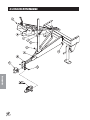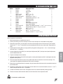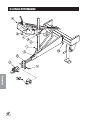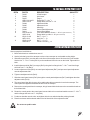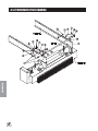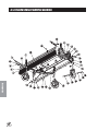
1
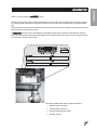
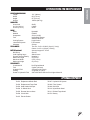
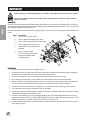
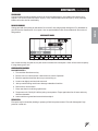
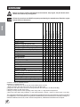
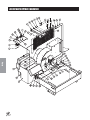
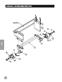
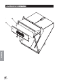
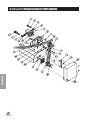
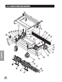
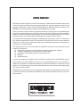
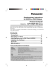
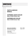
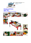
PARTS & SERVICE
MANUAL
SWEEP STAR V62
With Electric Clutch
Models 78-200-A
Starting Serial # 78139
SMITHCO PRODUCT SUPPORT
1-800-891-9435
Hwy SS and Poplar Avenue, Cameron WI 54822
E-mail: [email protected]
November, 2002
Introduction
CONTENTS
Introduction .......................................... 1-10
Service
Diagrams
Parts
Accessories
Reference
Introduction ................................................................................... 1-3
Safe Practices ............................................................................. 2
Specifications .............................................................................. 3
Optional Equipment ..................................................................... 3
Service ........................................................................................ 4-10
Maintenance ............................................................................. 4-6
Overloading Debris Hopper and Vacuum Housing Wear ............... 7
Service Chart Kawasaki 22hp ...................................................... 8
End User’s Service Chart ............................................................. 9
Adjustments .............................................................................. 10
Storage ...................................................................................... 10
Diagrams ................................................................................... 12-15
Wiring Diagram ..................................................................... 12-13
Wiring Schematic ...................................................................... 13
Parts .......................................................................................... 16-37
Body and Frame ................................................................... 16-17
Engine and Controls ............................................................. 18-20
Pulley and Pump .................................................................. 22-23
Blower and Vacuum Housing ................................................ 24-25
Finger Reel ........................................................................... 26-27
Brush Reel ........................................................................... 28-29
Reel and Hydraulic Pump ..................................................... 30-31
Hopper .................................................................................. 32-33
78-415 2-Bank Hydraulic Valve ............................................. 34-35
Rear Axle / Electric Brake .................................................... 36-37
Accessories ............................................................................... 38-63
78-201 Replacement Brush Reel .......................................... 38-39
78-202 Replacement Finger Reel .......................................... 38-39
78-205 Remote Vacuum Hose .............................................. 40-41
78-204 5th Wheel Hitch ......................................................... 42-43
78-206 Clevis Hitch ............................................................... 44-45
78-209 Ball Hitch .................................................................. 46-47
78-207 Hydraulic Lift Kit ........................................................ 48-49
78-363 3-Bank Hydraulic Valve ............................................. 50-51
78-203 Hard Surface Sweeper ............................................. 52-53
78-208 Filter System ............................................................ 54-55
78-210 & 78-211 Reel and Hydraulic Pump ........................... 56-57
78-210 Nylon Brush Head ..................................................... 58-59
78-211 Rubber Finger Head ................................................... 60-61
78-215 Electric Brake ........................................................... 62-63
Reference .................................................................................. 65-66
Decal List .................................................................................. 65
Quick Reference Replacement Parts ......................................... 66
Warranty ........................................................... Inside Back Cover
Thank you for purchasing a
product.
Read this manual and all other manuals pertaining to the Sweep Star V62 carefully as they have safety, operating, assembly and maintenance instructions. Failure to do so could result in personal injury or equipment damage.
Keep manuals in a safe place after operator and maintenance personnel have read them. Right and left sides are
from the operator’s seat, facing forward.
All
machines have a Serial Number and Model Number. Both numbers are needed when ordering
parts. The serial number plate on the Sweep Star V62 is located on the left front frame. Refer to engine manual
for placement of engine serial number.
For easy access record your Serial and Model numbers here.
Information needed when ordering replacement parts:
1. Model Number of machine
2. Serial Number of machine
3. Name and Part Number of part
4. Quantity of parts
1
Introduction
INTRODUCTION
SAFE PRACTICES
Introduction
1.
It is your responsibility to read this manual and all publications associated with this machine (engine, accessories and attachments).
2.
Never allow anyone to operate or service the machine or its attachments without proper training and instructions.
Never allow minors to operate any equipment.
3.
Learn the proper use of the machine, the location and purpose of all the controls and gauges before you operate
the equipment. Working with unfamiliar equipment can lead to accidents.
4.
Wear all the necessary protective clothing and personal safety devises to protect your head, eyes, ears, hands
and feet. Operate the machine only in daylight or in good artificial light.
5.
Inspect the area where the equipment will be used. Beware of overhead obstructions and underground obstacles. Stay alert for hidden hazards.
6.
Never operate equipment that is not in perfect working order or without decals, guards, shields, or other protective devices in place.
7.
Never disconnect or bypass any switch.
8.
Carbon monoxide in the exhaust fumes can be fatal when inhaled, never operate a machine without proper
ventilation.
9.
Fuel is highly flammable, handle with care.
10.
Keep engine clean. Allow the engine to cool before storing and always remove the ignition key.
11.
Never use your hands to search for oil leaks. Hydraulic fluid under pressure can penetrate the skin and cause
serious injury.
12.
This machine demands your attention. To prevent loss of control or tipping of the vehicle:
13.
A.
Use extra caution in backing up the vehicle. Ensure area is clear.
B.
Do not stop or start suddenly on any slope.
C.
Reduce speed on slopes and in sharp turns. Use caution when changing directions on slopes.
D.
Stay alert for holes in the terrain and other hidden hazards.
E.
Run up and down slopes, never across the face.
Before leaving operator’s position for any reason:
A
Disengage all drives.
B.
Lower all attachments to the ground.
C.
Shut engine off and remove the ignition key.
14. Keep hands, feet and clothing away from moving parts. Wait for all movement to stop before you clean, adjust or
service the machine.
15.
The rubber fingers, sweeper and vacuum pick up and propel debris and small objects in its path during operation. Keep the area of operation clear of all bystanders.
16.
Never carry passengers.
17.
Stop engine before making repairs/adjustments or checking/adding oil to the crankcase.
18.
Use parts and materials supplied by SMITHCO only. Do not modify any function or part.
19.
Do not remove the radiator cap when the engine is hot. When cooled, loosen cap slightly to the stop to relieve
any pressure before removing the cap completely.
20.
Avoid sharp turns. Watch the tires of the tractor while turning to make sure they do not contact the tongue of the
Sweep Star V62.
21.
Shut down power source before attempting to unclog any part of the machine.
22.
If reel deck begins to vibrate abnormally, immediately shut off power and determine the cause.
23.
Do not tow on public roads.
These machines are intended for professional maintenance on golf courses, sports turf, and any other
area maintained turf and related trails, paths and lots. No guaranty as to the suitability for any task is
expressed or implied.
2
WEIGHTS AND DIMENSIONS
Length
Width
Height
Weight
151" (384 cm)
68" (172 cm)
87" (221 cm)
1500 lb (680 kg)
SOUND LEVEL
At ear level
At 3 ft (0.914 m)
At 30 ft (9.14 m)
98 dB
104 dB
86 dB
ENGINE
Make
Model#
Horsepower
Fuel
Cooling System
Lubrication System
Alternator
TIRES & WHEELS
Introduction
SPECIFICATIONS FOR SWEEP STAR V62
Kawasaki
FD661D
22 Hp (16 kW)
Unleaded 87 Octane
Gasoline Minimum
Liquid Cooled
Full Pressure
20 Amp
Two 24 x 13.00 x 12 NHS (18 psi (1.3 bar))
Castor: 9 x 3.5 x 4 (20 psi (1.4 bar))
BATTERY (optional)
BCI Group
Cold Cranking Amps
Ground Terminal Polarity
Maximum Length
Maximum Width
Maximum Height
Automotive type 45- 12 volt
Size 45
480 minimum
Negative (-)
9" (23 cm)
5.38" (14 cm)
9" (23 cm)
FLUID CAPACITY
Crankcase Oil
Fuel
Hydraulic Fluid
Cooling
Grade of Hydraulic Fluid
See Engine Manual
5 gallon (19 liters)
2.88 gallon (10.9 liters)
2.8 quarts (2.7 liters)
SAE 10W-40 API Service SJ or higher Motor Oil
OPTIONAL EQUIPMENT
78-201 Replacement Brush Reel
78-207 Hydraulic Lift System
78-202 Replacement Finger Reel
78-208 Filter System
78-203 Hard Surface Sweeper
78-209 Ball Hitch
th
78-204 5 Wheel Hitch
78-210 Nylon Brush Head
78-205 Remote Vacuum Hose
78-211 Rubber Finger Head
78-206 Clevis Hitch
22-073 Battery
78-215 Electric Braker
3
MAINTENANCE
Before servicing or making adjustments to machine, stop engine and remove key from ignition.
Use all procedures and parts prescribed by the manufacturer's. Read the engine manual
before operation.
Service
LUBRICATION
Use No. 2 General Purpose Lithium Base Grease and lubricate every 100 hours. The Sweep Star V62 has seventeen grease fittings. All bearings are sealed bearings. When inserting grease, be careful not to ruin the seal, if
this happens, replace the bearing at once.
Be sure to wipe grease fitting clean before injecting grease. Give only one or two pumps of grease at each lubrication.
REF#
1
LOCATION
One on all four castor wheels.
2
One on right and left hopper door arms.
3
One on each mounted bearing for reel shaft.
4
One on right and left deck lift arm.
5
one on all four castor wheel mount
brackets.
6
One on the jack stand.
7
Two on machine control panel
that go to the blower shaft
mounted bearing.
HYDRAULIC OIL
1. Use SAE 10W-40 API Service SJ or higher motor oil.
2. For proper warranty, change oil every 500 hours or annually, which ever is first and change the filter after
the first 20 hours, then at 100 hours, then every 250 hours thereafter.
3. The oil level should be 2" to 21/2" from top of the tank when fluid is cold. Do not overfill.
4. After changing oil and/or filter, run the machine for a few minutes. Check oil level and for leaks.
5. Always use caution when filling hydraulic oil tank or checking level to keep system free of contaminants.
Check and service more frequently when operating in extremely cold, hot or dusty conditions.
6. If natural color of fluid is now black or smells burnt, it is possible that an overheating problem exists.
7. If fluid becomes milky, water contamination may be a problem.
8. If either of the above conditions happen, change oil and filter immediately after fluid is cool and find cause.
Take fluid level readings when system is cold.
9. In extreme temperatures you can use straight weight oil. We recommend SAE 30W API Service SJ or
higher when hot (above 90°F (33°C)) and SAE 10W API Service SJ or higher when cold (below 32°F (0°C))
ambient temperature. Use either motor oil or hydraulic oil, but do not mix.
10. Oil being added to the system must be the same as what is already in the tank. Mark tank fill area as to
which type you put in.
4
MAINTENANCE (CONTINUED)
ENGINE OIL KAWASAKI
Change and add oil according to chart below. Do not overfill. Use a high quality detergent oil. For Kawasaki engine API Service Classification: SJ or higher. Use no special additives with recommended oils. Do not mix oil
with gasoline.
SAE VISCOSITY GRADES
Starting Temperature Range Anticipated Before Next Oil Change
Use of multi-viscosity oils (10W-30, etc) will result in increased oil consumption. Check oil level more frequently
if using these types of oils.
WHEEL MOUNTING PROCEDURE
MACHINE WHEELS
1. Turn machine off and remove key.
2. Be sure unit is on a level surface. Unhitch from tow vehicle if possible.
3. Block the opposite wheel then the one you are working on.
4. Loosen nuts slightly on wheel to be removed.
5. Jack up machine being careful not to damage underside of machine.
6. Remove nuts, remove wheel.
7. Place new wheel on hub lining up bolt holes.
8. Torque nuts to 64-74 ft/lb (87-100 Nm) using a cross pattern. Torque again after first 10 hours and every
200 hours thereafter.
9. Lower machine to ground and remove blocks and jack.
FILTER SYSTEM
Filter pack may be cleaned by shaking or spraying off with low pressure water. Filter will disintegrate if high
pressure is used on it.
5
Service
TIRE PRESSURE
Caution must be used when inflating a low tire to recommended pressure. Over inflating can cause tires to
explode. Tires on the machine should be 18 psi (1.3 bar), castor wheels should be 20 psi (1.4 bar). Improper
inflation will reduce tire life considerably.
MAINTENANCE (CONTINUED)
BATTERY
Batteries normally produce explosive gases which can cause personal injury. Do not allow flames, sparks or any
ignited object to come near the battery. When charging or working near battery, always shield your eyes and
always provide proper ventilation.
Battery cable should be disconnected before using “Fast Charge”.
Charge battery at 15 amps for 10 minutes or 7 amps for 30 minutes. Do not exceed the recommended charging
rate. If electrolyte starts boiling over, decrease charging.
Always remove grounded (-) battery clamp first and replace it last. Avoid hazards by:
Service
1. Filling batteries in well-ventilated areas.
2. Wear eye protection and rubber gloves.
3. Avoid breathing fumes when electrolyte is added.
4. Avoid spilling or dripping electrolyte.
Battery Electrolyte is an acidic solution and should be handled with care. If electrolyte is
splashed on any part of your body, flush all contact areas immediately with liberal amounts
of water. Get medical attention immediately.
JUMP STARTING
Use of booster battery and jumper cables. Particular care should be used when connecting a
booster battery. Use proper polarity in order to prevent sparks.
To jump start (negative grounded battery):
1. Shield eyes.
2. Connect ends of one cable to positive (+) terminals of each battery, first (A) then (B).
3. Connect one end of other cable to negative (-)
terminal of "good" battery (C).
4. Connect other end of cable (D) to engine block on
unit being started (NOT to negative (-) terminal of
battery)
To prevent damage to other electrical components on
unit being started, make certain that engine is at idle speed before disconnecting jumper cables.
6
OVERLOADING DEBRIS HOPPER AND WEAR ON VACUUM HOUSING
OVERLOAING DEBRIS HOPPER
Smithco Sweeper-Vacs are designed to carry the following maximum loads:
Model 72-000 Big Vac
1500 lbs. (608 kg)
Model 78-200 & 78-500 Sweep Star V62
860 lbs. (400 kg)
PLEASE NOTE THE FOLLOWING:
1. Loads heavier than that will damage the unit.
3. Overloading is particularly easy when collecting aerifier cores.
4. The hoppers on the Big Vac and V62 are large in order to hold 7 and 4 cubic yards respectively, of thatch,
grass clippings, leaves and trash.
5. They will not hold 7 or 4 cubic yards of aerifier cores.
6. The maximum depth (in the debris hopper) of aerifier cores is:
Model 72-000 Big Vac
12 in. (30 cm)
Model 78-200 & 78-500 Sweep Star V62
40 in. (101 cm)
VACUUM HOUSING WEAR
The Big Vac & V62 are fitted with a wear resistant liner in the vacuum housing. This will provide additional husing
life. Be sure the following points are explained to the user:
1. The vacuum housing and impeller must be cleaned each time the unit is used so the housing liner is
inspected daily. Only Smithco Sweeper-Vacs provide a clean out/inspection port for easy inspection and
cleaning.
2. When bare steel is visible at any point in the housing lining, the lining must be replaced. It is expected the
liner will wear and be replaced. It is a vast improvement over competitive units with no liners.
3. Replacement of the liner or the vacuum housing due ti wear is normal and is not covered by warranty.
4. Collection of aerifier cores causes extreme wear on the liner (and if unchecked, on the housing).
5. Caution users that, while Smithco Sweeper-Vacs do an excellent job collecting cores, the lining (and the
housing) will wear quickly in such use.
RUBBERIZED BOOT
The rubberized boot between main unit and sweeper head is subject to wear and damage from debris. Unless
defecetive, replacement of this boot is not covered by warranty.
MAXIMUM LOAD CAPACITY
There are decals on each side of the hopper to indicate the maximum depth of aeration cores. The maximum
depth for aeration cores in the hopper is 40" (101 cm). The maximum depth of sand and dirt in hopper is 20"
(50cm). The maximum load capacity of the Sweep Star V-62 is 860 lbs (400 kg).
Overloading will cause damage that is not covered by the warranty.
7
Service
2. Such damage is not covered by warranty.
SERVICE CHART
Before servicing or making adjustments to the machine, stop engine, set park break, block
wheels and remove key from ignition.
400 Hours
R
R
C
C
C
C
Every 500 Hours/Yearly
300 Hours
250 Hours
200 Hours
C R R R
R
R
C
C C
C
R C C
R
R C C C R
R C C
C
Daily
100 Hours
Service
¤£ Engine Oil
Engine Oil Filter
Engine for Leaks and Loose Parts
‡ Air Cleaner (Paper Element)
‡ Air-Cleaner (Foam Element every 25 hours)
Spark Plugs (Clean and Gap/Replace)
Valve Clearance
Idle Speed
‡ Cooling System
Belts and Hoses
* Tire Pressure
Visual Inspection of Tires
Fuel Level
Fuel Filter
Hydraulic Oil
†Hydraulic Oil Filter
Hydraulic System for Leaks and Loose Parts
Battery Electrolyte Level
Clean Battery Terminals
§ Torque Lug Nuts
Lubricate Reel and Blower Shaft Bearings
Lubricate Castor Wheels (Every 25 hrs)
As Required
Follow all procedures and ONLY use parts prescribed by the manufacturer. Read the engine
manual before maintenance.
R
R
C
R
R
R
C
C
C
C
C
C C
C C C
C
C
C
C
C C
C C C
C
C C
C C C
C C
R
R
C
C C
C C R
R
R
C
C C
C C C
C C
C C C
C
C
C
C C
C
C
C C
C=Check or Clean at specified intervals
R=Replace at specified intervals
* Tire pressure: Machine Tires 18 psi (1.3 bar) Castor Wheels 20 psi (1.4 bar)
† Replace hydraulic filter after the first 20, 100, and every 250 there after.
§ Torque tire nuts after the first 10 hours and every 200 hours there after (64 to 74 ft/lb (87-100 Nm))
¤ Kawasaki change oil after first 8 hours.
£ Change oil every 25 hours when operating under heavy load or in high ambient temperatures.
‡ Clean more often under dusty conditions or when airborne debris is present , replace air cleaner parts, if very dirty.
The suggested maintenance checklist is not offered as a replacement for the manufacturer’s engine manual but
as a supplement. You must adhere to the guidelines established by the manufacturer for warranty coverage. In
adverse conditions such as dirt, mud or extreme temperatures, maintenance should be more frequent.
8
Service
Every 500 Hours/Yearly
400 Hours
300 Hours
250 Hours
200 Hours
100 Hours
As Required
Daily
END USER'S SERVICE CHART
¤£ Engine Oil
Engine Oil Filter
Engine for Leaks and Loose Parts
‡ Air Cleaner (Paper Element)
‡ Air-Cleaner (Foam Element every 25 hours)
Spark Plugs (Clean and Gap/Replace)
Valve Clearance
Idle Speed
‡ Cooling System
Belts and Hoses
* Tire Pressure
Visual Inspection of Tires
Fuel Level
Fuel Filter
Hydraulic Oil
†Hydraulic Oil Filter
Hydraulic System for Leaks and Loose Parts
Battery Electrolyte Level
Clean Battery Terminals
§ Torque Lug Nuts
Lubricate Reel and Blower Shaft Bearings
Lubricate Castor Wheels (Every 25 hrs)
C=Check or Clean at specified intervals
R=Replace at specified intervals
* Tire pressure: Machine Tires 18 psi (1.3 bar) Castor Wheels 20 psi (1.4 bar)
† Replace hydraulic filter after the first 20, 100, and every 250 there after.
§ Torque tire nuts after the first 10 hours and every 200 hours there after (64 to 74 ft/lb (87-100 Nm))
¤ Kawasaki change oil after first 8 hours.
£ Change oil every 25 hours when operating under heavy load or in high ambient temperatures.
‡ Clean more often under dusty conditions or when airborne debris is present , replace air cleaner parts, if very dirty.
9
ADJUSTMENTS
Service
ADJUSTMENT OF BELT TENSIONER
There are two belt tensioners on the Sweep Star V62. One
controls the tension on the belt from the engine to blower
shaft the other controls the belt on the finger or brush reel.
The proper tension of the idler should be 12 to 15 as per the
gauge (A) on the side of the tightener. Over tightening the belt
will shorten the life of the belt and the machine may not perform to the best of its ability. To adjust belt tensioner, loosen
bolt holding tensioner. Bring idler pulley tight to belts and turn
tensioner into belts to 15°. Tighten holder bolt.
CASTOR WHEELS
Install castor wheels onto the brush/finger head assembly. You may put the machine bushings and spacers (A) on in any combination to get desired height. You should leave one
machine bushing on the very bottom and one on the very top next to the lockpin. Check the
tire pressure on Castor Wheels they should be 20 psi (1.4 bar).
STORAGE
When storing, remove the key from the key switch to avoid unauthorized persons from operating machine.
1. Before storing clean machine thoroughly.
2. Check bolts and nuts, tighten as necessary.
3. Make all repairs that are needed and remove any debris.
4. Remove the battery, adjust the electrolyte level and recharge it. Store the battery in a dry, dark place.
5. Store in a clean and dry area, but NOT near a stove, furnace or water heater which uses a pilot light or any
device that can create a spark.
6. Engines stored over 30 days need to be protected or drained of fuel to prevent gum from forming in a fuel
system or on essential carburetor parts. Check the engine manual and follow the instructions for the
storage of the engine.
10
NOTES
11
WIRING DRAWING
Diagrams
12
WIRING PARTS LIST
1
2
3
4
5
6
7
8
9
10
11
12
13
14
15
16
PART#
DESCRIPTION
78-342
12-017
78-343
12-016
76-310
8935
78-340
78-341
Wire, Hour Meter to Ground
Hour Meter
Wire, Hour Meter to Buss Bar
Ignition Switch
Key Set (comes with 12-016)
Buss Bar
Oil Light
Temperature Light
Fuel Pump (Part of Engine)
Wire Harness (includes all wire colors with *)
Battery Cable Black
Battery (optional)
Red Battery Cable with Boot
Circuit Breaker Wire
30 Amp Circuit Breaker
Circuit Breaker Boot
Electric Clutch
Toggle Switch
Switch Boot
78-367
22-054
22-073
78-325
48-144
8975
8977
78-368
15-314
15-472
QUANTITY
1
1
1
1
1
1
1
1
1
1
1
1
1
1
1
1
1
1
1
Diagrams
REF#
13
HYDRAULIC DRAWING
Diagrams
14
HYDRAULIC PARTS LIST
PART#
DESCRIPTION
1
2
3
78-247
78-413
23-006
23-031
78-249
78-250
78-415
78-246
78-248
13-584
8917-14
18-222
78-414
75-714
Hydraulic Hose (brush motor to valve)
Hydraulic Pump
Oil Filter
Filter Element (replacement only)
Hydraulic Hose (pump to valve)
Hydraulic Hose (return to tank )
2-Bank Hydraulic Valve
Hydraulic Hose (rear hyd. cyl. to front valve)
Hydraulic Hose (front hyd. cyl. to rear valve)
Oil Tank
Suction Hose 5/8 ID x 14
Hose Clamp
Hydraulic Motor
Hydraulic Cylinder
4
5
6
7
8
9
10
11
12
HYDRAULIC PRESSURES
Pump Displacement
QUANTITY
2
1
1
1
1
1
1
1
1
1
1
2
1
1
Diagrams
REF#
.4 in3/rev
Pump Input Speed (up to)
3600 rpm
Max. Operating Pressure
2500 psi
Max. Inlet Vacuum
10 in. Hg
Max. Case Pressure
80 psi
78-415 Hydraulic Valve (2 bank)
2500 psi
15
BODY AND FRAME DRAWING
Parts
16
BODY AND FRAME PARTS LIST
1
2
3
4
5
6
7
8
9
10
11
12
13
14
15
16
17
18
19
20
21
22
23
24
25
26
27
28
29
30
31
PART#
DESCRIPTION
HSTP-14-20-075
78-253
78-274
78-315
78-274
HB-516-18-075
HNFL-516-18
HBFL-516-18-075
HNFL-516-18
78-260
75-714
14-254
78-265
78-272
78-319
HNCL-12-13
HN-12-13
HW-12
HB-12-13-250
78-266
HNFL-38-16
78-264
19-205
HB-38-16-575
78-387
8979-61
HSD-8-050
78-316
78-274
HB-516-18-075
HNFL-516-18
78-339
78-274
78-216
78-221
78-221-01
78-221-02
HNL-12-20
HB-12-13-150
HW-12
HNTL-12-13
78-270
78-240
78-255
HLC-A-200
HSDPS-14-075
78-281
78-269
78-313
HSDPS-14-075
18-169
HCP-58-175
HHP-18-100
78-345
Phillips Truss Head Machine Screw 1/4 - 20 x 3/4
Right Guard
Cage Nuts
Right Guard Mount
Cage Nuts
Bolt 5/16 - 18 x 3/4
Flange Whiz Lock Nut 5/16 - 18
Flange Bolt 5/16 -18 x 3/4
Flange Whiz Lock Nut 5/16 - 18
Right Hopper
Hydraulic Cylinder
Seal Kit
Cross Bar
Hopper Cover
Hopper Door Adjustment
Center Lock Nut 1/2 - 13
Nut 1/2 - 13
Washer 1/2
Bolt 1/2 - 13 x 21/2
Hopper Door
Flange Whiz Lock Nut 3/8 - 16
Left Door Arm
Spring
Bolt 3/8 - 16 x 53/4
Weatherstripping Bracket
Door Weatherstripping
Drill Screw #8 x 1/2
Left Guard Mount
Cage Nuts
Bolt 5/16 - 18 x 3/4
Flange Whiz Lock Nut 5/16 -18
Left Guard
Cage Nuts
Rear Axle
Tire and Wheel
Tire 24 x 13 -12 6 Ply
Wheel
Lug Nut 1/2 - 20 (part of 78-216)
Bolt 1/2 - 13 x 11/2
Washer 1/2
Lock Nut 1/2 - 13
Left Brush Guard
Jack
Main Frame
Loom Clamp
Stainless Steel Pan Head Drill Screw 1/4 x 3/4
Operator Control Panel
Right Brush Guard
Radiator Guard
Stainless Steel Pan Head Drill Screw 1/4 x 3/4
Adapter 3/8 SAE
Clevis Pin 5/8 x 13/4
Cotter Pin 1/8 x 1
Clear Lexan Window
QUANTITY
8
1
2
1
2
2
2
8
8
1
1
1
1
1
2
2
2
4
2
1
4
1
2
2
2
2
32
1
3
3
3
1
4
1
2
2
2
10
4
4
4
1
1
1
4
4
1
1
1
3
2
2
2
1
Parts
REF#
17
ENGINE AND CONTROLS DRAWING
Parts
18
ENGINE AND CONTROLS PARTS LIST
1
2
3
4
5
6
7
8
9
10
11
12
13
14
15
16
17
18
19
20
21
22
23
24
PART#
DESCRIPTION
HSM-10-32-063
HWL-10
HN-10-32
34-159
78-281
78-217
HSTP-14-20-075
HNFL-14-20
HSM-8-32-050
HWL-8
HN-8-32
78-337
HN-38-24
12-016
78-415
78-418
HB-14-20-200
HW-14
HNFL-14-20
78-342
HN-14-20
78-343
12-017
11-086
78-341
78-340
HG-18-45
18-339
HSTP-14-20-075
HNFL-14-20
78-317
78-254
78-307
18-338
78-324
8935
HSM-8-32-075
HWL-8
HN-8-32
Machine Screw #10 - 32 x 5/8
Lockwasher #10
Nut #10 - 32
Throttle Mounting Bracket
Operator Control Panel V62
Decal, Operator Control Panel V62
Phillips Truss Head Machine Screw 1/4 - 20 x 3/4
Flange Whiz Lock Nut 1/4 - 20
Machine Screw # 8 - 32 x 1/2
Lockwasher #8
Nut # 8 - 32
Throttle
Nut 3/8 - 24
Ignition Switch
2-Bank Valve
Bent Handle
Bolt 1/4 - 20 x 2
Washer 1/4
Flange Whiz Lock Nut 1/4 - 20
Wire, Hour Meter to Ground
Nut 1/4 - 20
Wire, Hour Meter to Buss Bar
Hour Meter
Choke Cable
Temperature Light
Oil Light
Grease Fitting 1/8 Pipe x 45°
Anchor Coupling
Phillips Truss Head Machine Screw 1/4 - 20 x 3/4
Flange Whiz Lock Nut 1/4 - 20
Front Guard Mount
Front Guard
Decal, Machine Control Panel V62
Male Connector
3
/16 Brake Line 20"
Bus Bar
Machine Screw #8 - 32 x 3/4
Lock Washer #8
Nut #8 - 32
Electric Fuel Pump (part of engine)
Fuel Hose 1/4 x 56"
Hose Clamp
Loom Clamp 5/8
Stainless Steel Pan Head Drill Screw 1/4 x 3/4
8800-56
18-186
HLC-A-58
HSDPS-14-075
QUANTITY
4
4
4
1
1
1
4
4
4
4
4
1
2
1
1
2
2
2
2
1
1
1
1
1
1
1
2
2
8
8
1
1
1
2
2
1
2
2
2
1
1
5
2
2
Parts
REF#
(Continued on next page)
19
ENGINE AND CONTROLS DRAWING
Parts
20
ENGINE AND CONTROLS PARTS LIST
25
26
27
28
29
30
31
32
33
34
35
36
37
38
39
PART#
DESCRIPTION
10-197
18-220
50-403
HSSHS-38-16-063
78-235
78-232
HKSQ-14-100
78-218
34-169
15-314
15-472
78-368
76-340
HB-516-18-125
HW-516
HNTL-516-18
78-370
HB-38-16-175
HWL-38
Exhaust Pipe
Muffler Clamp 11/4
In-line Fuel Filter
Set Screw 3/8 - 16 x 5/8 (part of 78-235)
Hub 11/8
Pulley
Machine Key 1/4 x 1/4 x 1
Engine, 22 HP Kawasaki
Coolant Tank Kit (part of engine)
Toggle Switch
Switch Boot
Electric Clutch
Clutch Strap
Bolt 5/16 - 18 x 11/4
Washer 5/16
Lock Nut 5/16 - 18
Washer
Bolt 3/8 - 16 x 13/4
Lockwasher 3/8
QUANTITY
1
1
1
2
1
1
1
1
1
1
1
1
1
2
3
2
1
1
1
Parts
REF#
21
PULLEY AND PUMP DRAWING
Parts
22
PULLEY AND PUMP PARTS LIST
1
2
3
4
5
6
7
8
9
10
11*
12
13
14
17
18
19
20
21
22
23
24
25
26
27
28
29
30
31
*
PART#
DESCRIPTION
HB-12-13-250
HMB-12-14
78-275
HNCL-12-13
16-013
78-224
HBM-10-1.5-30
HWLM-10
78-232
78-235
HSSHS-38-16-063
78-218
HMB-114-10
78-368
78-236
HSSHS-12-13-100
78-234
78-413
HWK-316-063
HB-38-16-150
HW-38
HNTL-38-16
23-006
23-031
8917-14
18-040
18-229
78-278
23-121
13-584
13-586
HSM-8-32-050
HWS-8
13-586-01
13-586-02
78-277
HB-14-20-075
HWL-14
HW-14
HB-14-20-075
HNFL-14-20
18-118
23-139
18-008
18-332
18-331
78-227
Bolt 1/2 - 13 x 21/2 (part of 78-224)
Machine Bushing 1/2 - 14GA
Spacer (part of 78-224)
Center Lock Nut 1/2 - 13 (part of 78-224)
Idler Pulley
Belt Tensioner
Metric Bolt 10-1.5 x 30 (part of 78-224)
Metric Lockwasher #10 (part of 78-224)
Pulley
Hub 11/8
Set Screw 3/8 - 16 x 5/8 (part of 78-235)
Engine, 22 HP Kawasaki
Machine Bushing 11/4 x 10GA
Electric Clutch
Hub 3/4
Set Screw 1/2 - 13 x 1 (part of 78-236)
Pulley 3-Groove (pump)
Hydraulic Pump
Woodruff Key 3/16 x 5/8
Bolt 3/8 - 16 x 11/2
Washer 3/8
Lock Nut 3/8 - 16
Oil Filter
Replacement Filter Only
Suction Hose 5/8 ID
Hose Clamp
90° Elbow
Front Oil Tank Bracket
Fitting
Oil Tank
Filter Breather
Machine Screw #8 - 32 x 1/2
Star Washer #8
Cap Gasket (part of 13-586)
Bottom Gasket (part of 13-586)
Rear Oil Tank Bracket
Bolt 1/4 - 20 x 3/4
Lockwasher 1/4
Washer 1/4
Bolt 1/4 - 20 x 3/4
Flange Whiz Lock Nut 1/4 - 20
Pipe Plug 1/8
Barb Fitting
Pipe Reducer
Adapter
Adapter
Belt
QUANTITY
1
2
1
1
1
1
1
1
1
1
2
1
1
1
1
2
1
1
1
2
4
2
1
1
2
1
1
1
1
1
6
6
1
2
1
4
4
4
4
4
1
2
1
1
1
1
Parts
REF#
NO OTHER PARTS ARE REPLACEABLE FOR HYDRAULIC PUMP.
23
BLOWER AND VACUUM HOUSING DRAWING
Parts
24
BLOWER AND VACUUM HOUSING PARTS LIST
1
2
3
4
5
6
7
8
9
10
11
12
13
14
15
16
17
18
19
20
21
22
23
24
25
26
27
28
29
30
PART#
DESCRIPTION
15-492
15-491
78-379
78-403
78-375
78-402
HWF-14-150
18-338
18-269
18-027
78-223
78-336
HKSQ-14-100
HB-716-14-150
HNTL-716-14
HSTP-14-20-075
HSTP-14-20-100
HNTL-14-20
HBFL-516-18-075
HNFL-516-18
HNTL-516-18
78-301
78-347
15-020
78-243
HB-38-16-100
HNFL-38-16
78-276
78-257
8803-80
78-293
15-039
8800-30
18-186
HB-14-20-075
HWL-14
HW-14
18-042
78-378
HB-516-18-100
HNFL-516-18
78-355
HLC-58
78-419
78-411
78-412
Cap w/ Gauge
Gas Tank, 5 Gallon w/ Insert
Trap Door
Trap Door Lining
Blower Housing
Blower Lining
Fender Washer 1/4 x 11/2
Male Connector
Coupling 1/8
Nipple 1/8 x 2
Mounted Bearing (11/8" Bore)
Vacuum Housing Shaft
Machine Key 1/4 x 1/4 x 1
Bolt 7/16 - 14 x 11/2
Lock Nut 7/16 - 14
Phillips Truss Head Machine Screw 1/4 - 20 x 3/4
Phillips Truss Head Machine Screw 1/4 - 20 x 1
Top Lock Nut 1/4 - 20
Flange Bolt 5/16 -18 x 3/4
Flange Whiz Lock Nut 5/16 - 18
Top Lock Nut 5/16 - 18
Balanced Fan
Spiral Spring Pin
Handle Grip
Sweeper Boot
Bolt 3/8 - 16 x 1
Flange Whiz Lock Nut 3/8 - 16
Vacuum Housing Support
Vacuum Housing
Trim Black
Cover Plate
Fuel Valve
Fuel Hose 1/4 x 30"
Hose Clamp
Bolt 1/4 - 20 x 3/4
Lockwasher 1/4
Washer 1/4
Reducer Bushing
Gas Tank Mount
Bolt 5/16 - 18 x 1
Flange Whiz Lock Nut 5/16 - 18
Splice
Loom Clamp 5/8
Bottom Lining Holder
Top Lining Holder
Wear Cover
QUANTITY
1
1
1
1
1
1
32
2
2
2
2
1
1
8
8
20
12
32
11
4
7
1
2
1
1
2
2
1
1
1
1
1
1
1
4
4
4
1
1
2
2
1
1
1
1
1
Parts
REF#
25
FINGER REEL DRAWING
Parts
26
FINGER REEL PARTS LIST
1
2
3
4
5
6
7
8
9
10
11
12
13
14
15
16
17
18
19
20
21
22
23
24
25
26
27
28
29
30
31
32
33
34
35
36
37
38
39
40
41
42
43
44
45
46
47
PART#
DESCRIPTION
HMB-58-14
HN-58-11
HB-58-11-300
HNTL-58-11
HG-14-28-45
78-241
78-284
20-018
15-020
HB-38-16-125
HNTL-38-16
78-286
78-283
20-018
78-285
8820-8
HCP-34-250
HB-14-20-075
HNFL-14-20
78-344
78-271
HB-12-13-600
78-322
42-213
42-212
HMB-34-10
HNTL-12-13
72-056
HST-14-20-075
HNFL-14-20
42-202
42-202-01
42-202-02
78-287
78-327
78-242
HKSQ-14-100
78-303
78-297
78-326
HNFL-516-18
78-392
HG-14-28-180
18-223
72-136
HNFL-38-16
HB-38-16-125
78-222
72-053
42-539
78-401
8803-80
78-255
HB-38-16-250
HW-38
HNFL-38-16
78-393
HHP-18
8820-3
78-421
Machine Bushing 5/8 x 14GA
Nut 5/8 - 11
Bolt 5/8 - 11 x 3
Lock Nut 5/8 - 11
Grease Fitting 1/4 - 28 x 45°
Chain Connector
Left Hand Deck Lift
Bushing (part of 78-284)
Hand Grip
Bolt 3/8 - 16 x 11/4
Lock Nut 3/8 - 16
Left Hand Lift Arm Latch
Right hand Deck Lift
Bushing (part of 78-283)
Right Hand Lift arm Latch
Machine Chain Straight Link
Clevis Pin 3/4 x 21/2
Bolt 1/4 - 20 x 3/4
Flange Whiz Lock Nut 1/4 - 20
Strip Brush Holder (drilled)
Reel Lift Rod
Bolt 1/2 -13 x 6
Strip Brush
Axle Bearing
Castor Wheel Bearing
Machine Bushing 3/4 x 10GA
Lock Nut 1/2 - 13
Plastic Belt Guard
Truss Head Machine Screw 1/4 - 20 x 3/4
Flange Whiz Lock Nut 1/4 - 20
Tire & Wheel
Tire 9 x 3.5 x 4 Ply
Wheel
Finger Clamp 13"
Finger Clamp 10.5"
Sweeper Finger
Machine Key 1/4 x 1/4 x 1
Finger Reel Bar
Finger Clamp 10"
Finger Clamp 12"
Flange Whiz Lock Nut 5/16 - 18
Castor Fork
Grease Fitting 1/4 - 28 x 180° (part of 78-393)
Flange Bushing (part of 78-393)
Quick Spacer 10GA
Flange Whiz Lock Nut 3/8 - 16
Bolt 3/8 - 16 x 11/4
Mounted Bearing (1" bore)
Quick Spacer
Lynch Pin 5/16
Reel Housing
Trim Black
Main Frame
Bolt 3/8 - 16 x 2½
Washer 3/8
Flange Whiz Lock Nut 3/8 - 16
Castor Arm
Bridge Pin 1/8
Machine Chain Straight Link
Chain Connector
QUANTITY
6
2
2
2
2
8
1
1
2
4
4
1
1
1
1
2
4
5
5
1
2
4
1
4
8
8
4
1
4
4
4
4
4
1
1
81
1
1
17
1
40
4
2
4
12
8
8
2
24
4
1
1
1
4
4
4
2
4
2
4
Parts
REF#
27
BRUSH REEL DRAWING
Parts
28
BRUSH REEL PARTS LIST
1
2
3
4
5
6
7
8
9
10
11
12
13
14
15
16
17
18
19
20
21
22
23
24
25
26
27
28
29
30
31
32
33
34
35
36
37
38
39
40
41
42
PART#
DESCRIPTION
HMB-58-14
HN-58-11
HB-58-11-300
HNTL-58-11
HG-14-28-45
78-241
78-284
20-018
15-020
HB-38-16-125
HNTL-38-16
78-286
78-283
20-018
78-285
8820-8
HCP-34-250
HHP-18
HB-14-20-075
HNFL-14-20
78-344
78-271
HB-12-13-600
78-322
42-213
42-212
HMB-34-10
HNTL-12-13
72-056
HST-14-20-075
HNFL-14-20
HKSQ-14-100
78-348
78-321
42-202
42-202-01
42-202-02
78-392
HG-14-28-180
18-223
78-136
HNFL-38-16
HB-38-16-125
78-222
72-053
42-539
78-401
8803-80
HB-38-16-250
HW-38
HNFL-38-16
78-255
78-393
8820-3
78-421
Machine Bushing 5/8 x 14GA
Nut 5/8 - 11
Bolt 5/8 - 11 x 3
Lock Nut 5/8 - 11
Grease Fitting 1/4 - 28 x 45°
Chain Connector
Left Hand Deck Lift
Bushing (part of 78-284)
Hand Grip
Bolt 3/8 - 16 x 11/4
Lock Nut 3/8 - 16
Left Hand Lift Arm Latch
Right hand Deck Lift
Bushing (part of 78-234)
Right Hand Lift arm Latch
Machine Chain Straight Link
Clevis Pin 3/4 x 21/2
Bridge Pin 1/8
Bolt 1/4 - 20 x 3/4
Flange Whiz Lock Nut 1/4 - 20
Strip Brush Holder (drilled)
Reel Lift Rod
Bolt 1/2 - 13 x 6
Strip Brush
Axle Bearing
Castor Wheel Spacer
Machine Bushing 3/4 x 10GA
Lock Nut 1/2 - 13
Plastic Belt Guard
Truss Head Machine Screw 1/4 - 20 x 3/4
Flange Whiz Lock Nut 1/4 - 20
Machine Key 1/4 x 1/4 x 1
Shaft Spiral Brush
Spiral Brush
Tire and Wheel
Tire 9 x 3.5 x 4 Ply
Wheel
Castor Fork
Grease Fitting 1/8 x 28 x 180° (part of 78-393)
Flange Bushing (part of 78-393)
Quick Spacer 10GA
Flange Whiz Lock Nut 3/8 - 16
Bolt 3/8 - 16 x 11/4
Mounted Bearing (1" bore)
Quick SPacer 1/2"
Lynch Pin 5/16
Reel Housing
Trim Black
Bolt 3/8 - 16 x 2½
Washer 3/8
Flange Whiz Lock Nut 3/8 - 16
Main Frame
Castor Arm
Machine Chain Straight Link
Chain Connector
QUANTITY
6
2
2
2
2
8
1
1
2
4
4
1
1
1
1
2
4
4
5
5
1
2
4
1
4
8
8
4
1
4
4
2
1
1
4
4
4
4
2 per
4 per
12
8
8
2
24
4
1
1
4
4
4
1
2
2
4
Parts
REF#
29
REEL & HYDRAULIC PUMP DRAWING
Parts
30
REEL & HYDRAULIC PUMP PARTS LIST
1
2
3
4
5
6
7
8
9
10
11
12
13
14
15
16
17
18
19
20
21
22
23
24
25
26
27
28
29*
30
*
PART#
DESCRIPTION
18-246
78-228
78-229
18-334
18-009
18-333
HWK-316-063
78-259
HB-38-16-150
HNFL-38-16
78-232
78-237
HSSHS-38-16-063
16-013
HB-12-13-250
HMB-12-14
78-226
72-058
HBFL-516-18-075
HNFL-516-18
72-056
HST-14-20-075
HNFL-14-20
78-351
HSSHS-38-16-063
78-222
HB-38-16-125
HNFL-38-16
HKSQ-14-100
76-275
HB-38-16-100
HNFL-38-16
HNCL-12-13
78-224
HBM-10-1.5-30
HWLM-10
78-414
18-240
Male Elbow
Coupler 1/2"
Nipple 1/2"
Nipple
Elbow
Adapter
Woodruff key 3/16 x 5/8
Hydraulic Motor Mount
Bolt 3/8 - 16 x 11/2
Flange Whiz Lock Nut 3/8 - 16
Pulley
Hub 3/4
Set Screw 3/8 - 16 x 5/8 (part of 78-237)
Idler Pulley
Bolt 1/2 - 13 x 21/2 (part of 78-224)
Machine Bushing 1/2 x 14GA
Belt, Single
Belt Guard Mount Bracket
Flange Bolt 5/16 - 18 x 3/4
Flange Whiz Lock Nut 5/16 - 18
Plastic Belt Guard
Truss Head Machine Screw 1/4 - 20 x 3/4
Flange Whiz Lock Nut 1/4 - 20
Hub 1"
Set Screw 3/8 - 16 x 5/8 (part of 78-351)
Mounted Bearing (1" bore)
Bolt 3/8 - 16 x 11/4
Flange Whiz Lock Nut 3/8 - 16
Machine Key 1/4 x 1/4 x 1
Spacer (part of 78-224)
Bolt 3/8 -16 x 1
Flange Whiz Lock Nut 3/8 -16
Center Lock Nut 1/2 - 13 (part of 78-224)
Belt Tensioner
Metric Bolt 10-1.5 x 30 (part of 78-224)
Metric Lockwasher #10 (part of 78-224)
Hydraulic Motor
Pipe Adapter
QUANTITY
2
2
2
2
2
1
1
1
2
2
2
1
2
1
1
2
3
1
2
2
1
4
4
1
2
2
8
8
1
1
4
4
1
1
1
1
1
1
Parts
REF#
NO OTHER PARTS ARE REPLACEABLE FOR HYDRAULIC MOTOR.
31
HOPPER DRAWING
Parts
32
HOPPER PARTS LIST
1
2
3
4
5
6
7
8
9
10
11
12
13
14
16
17
18
19
20
21
22
23
24
25
26
27
28
29
30
31
32
33
34
35
36
37
38
39
40
41
42
NS
PART#
DESCRIPTION
78-305
HBFL-516-18-075
HNFL-516-18
78-272
78-395
HB-14-20-125
HNFL-14-20
78-384
HSM-8-32-150
78-549
78-345
HSTP-14-20-075
HNFL-14-20
75-714
18-169
78-260
78-262
78-304
HWL-14
HN-14-20
HBFL-38-16-075
HNFL-38-16
22-073
78-273
78-255
48-115
HSTP-14-20-075
78-263
78-389
78-282
78-292
78-388
78-264
78-291
78-265
HB-12-13-150
HW-12
HNTL-12-13
HMB-34-10
HP-18-150
78-319
HB-38-16-175
HNFL-38-16
78-383
78-394
78-386
78-382
78-385
8946-42
HSD-8-050
HSM-10-32-100
HWL-10
HN-10-32
78-547
78-548
18-154
78-546
78-550
HCP-58-175
HHP-18-100
Filter Insert
Flange Bolt 5/16 - 18 x 3/4
Flange Whiz Lock Nut 5/16 - 18
Hopper Cover
Filter Hood
Bolt 1/4 - 20 x 11/4
Flange Whiz Lock Nut 1/4 - 20
Flex Draw Latch
Machine Screw #8 - 32 x 11/2
Left Cylinder Plate
Clear Lexan Window
Phillips Truss Head Machine Screw 1/4 - 20 x 3/4
Flange Whiz Lock Nut 1/4 - 20
Hydraulic Cylinder
Adapter
Right Hopper
Chute
Battery Hold Down
Lockwasher 1/4
Nut 1/4 - 20
Flange Bolt 3/8 - 16 x 3/4
Flange Whiz Lock Nut 3/8 - 16
Battery (optional)
Hopper Mount
Main Frame
Adjustable Draw Latch
Phillips Truss Head Machine Screw 1/4 - 20 x 3/4
Right Door Arm
Right Hopper Door Latch
Hopper Strap
Door :Latch Support
Left Hopper Door Latch
Left Door Arm
Connecting Plate
Cross Bar
Bolt 1/2 - 13 x 11/2
Washer 1/2
Lock Nut 1/2 - 13
Machine Bushing 3/4 x 10GA
Cotter Pin 1/8 x 11/2
Tailgate Adjustment
Bolt 3/8 - 16 x 13/4
Flange Whiz Lock Nut 3/8 -16
Left Hopper
Filter Case
Hopper Filter
Screen
Wear Strip Bracket
Wear Strip 42"
Pan Head Drill Screw #8 x 1/2
Machine Screw #10 -32 x 1
Lockwasher #10
Nut #10 - 32
Left Cylinder Arm
Right Cylinder Plate
Rod End
Right CYlinder Arm
Crossbar Link Arm
Clevis Pin 5/8 x 13/4
Bridge Pin 1/8 x 1
QUANTITY
1
72
72
1
1
6
6
1
3
1
1
12
12
1
2
1
1
1
2
2
12
12
1
1
1
1
2
1
1
1
2
1
1
1
1
8
8
8
4
2
2
4
4
1
1
1
1
2
2
14
2
2
2
1
1
1
1
1
2
2
8979-61
Weather Stripping
2
Parts
REF#
33
78-415 2-BANK VALVE DRAWING
Parts
34
78-415 2-BANK VALVE PARTS LIST
1*
2*
3*
4*
5*
6*
7*
8*
9*
10*
11*
12*
13*
14
15
16
17
18
*
PART#
DESCRIPTION
78-415-01
78-415-02
78-415-03
78-415-04
78-415-05
78-415-06
78-415-07
78-415-08
78-415-09
78-415-10
78-415-11
78-415-12
78-415-13
18-168
18-202
18-169
78-418
Body (complete with spacer and check valve)
Spool HDM10
O-Ring Seal
Flanged Washer HDM10
Spacer
A Type Spool HDS11
Positioner
Plug
Lever Group HDS11
Metric Socket Screw M5 x .8 x 45
Positioner
Check Valve Assembly HDM12
3
/4 - 16 SAE 8 Screw Plug
Elbow 3/8 Straight Thread
Elbow
Adapter SAE 3/8
Bent Handle
Tapered Knob
78-415
2 – Bank Hydraulic Valve (includes all * items)
QUANTITY
1
1
6
3
3
3
2
3
3
6
1
1
3
2
4
4
2
3
Parts
REF#
35
REAR AXLE / ELECTRIC BRAKE PARTS LIST
Parts
36
REAR AXLE / ELECTRIC BRAKE PARTS LIST
REF#
1
2
3
4
5*
6
7*
8
9
10
11
PART#
DESCRIPTION
78-216
78-216-02
78-406
HP-18-200
78-119
HNAR-100-14
80-167
HNL-12-20
78-409
HN-716-20
HWL-716
78-408
Axle Complete
Grease Seal
Hub Assembly (includes all * items)
Cotter Pin 1/8 x 2
Bearing Cup and Cone
Slotted Jam Nut 1 - 14
Grease Cap
Lug Nut 1/2 - 20
RH Brake Assembly
Nut 7/16 - 20
Lockwasher 7/16
LH Brake Assembly
QUANTITY
1
2
2
2
2
2
2
10
1
8
8
1
78-410
Wire Harness
1
INSTALLATION INSTRUCTIONS
1. Block rear of machine up. Remove the rear tires and rear hubs. All parts except hubs to be reused.
2. There is a right and left brake (Ref 9 & 11). Place the brake on the axle and bolt to axle using the 7/16 - 20
nuts and lockwashers (Ref 10).
4. Put tires back on and hold in place with the 1/2-20 lug nuts (Ref 8). Put slotted jam nut (Ref 6), cotter pin
(Ref 4) and dust cap (Ref 7) on axle end.
5. Check all nuts and be sure they are tight.
6. Take the wire harness and hook the female space connectors to the male spade connectors on the brake
assemblies. Run wire harness up side of main frame to front of machine. Hold wire harness in place with
the tie straps.
7. Dealer must provide the connector that hooks to the tow unit. Place one side of connector onto wire
harness, connect the other half to the tow unit.
8. Check all connections and hardware. Test brakes before putting machine into service.
This unit is not intended for highway use.
37
Parts
3. Then place the hub and drum assembly (Ref 3) over the brake. Be sure to install the grease seal (Ref 2)
and the bearing cup and cone (Ref 5) as shown in the drawing.
78-201 REPLACEMENT BRUSH REEL DRAWING
78-202 REPLACEMENT FINGER REEL DRAWING
Accessories
38
78-201 REPLACEMENT BRUSH REEL PARTS LIST
REF#
1
2
3
4
5
6
PART#
DESCRIPTION
78-222
HB-38-16-125
HNFL-38-16
HG-14-28-180
78-348
HKSQ-14-100
78-321
Mounted Bearing
Bolt 3/8 - 16 x 11/4
Flange Whiz Lock Nut 3/8 - 16
Grease Fitting 1/4 -20 x 180° (comes with 78-222)
Spiral Brush Shaft
Machine Key 1/4 x 1/4 x 1
Spiral Brush
QUANTITY
2
8
8
2
1
2
1
78-202 REPLACEMENT FINGER REEL PARTS LIST
1
2
3
4
5
6
7
8
9
10
11
PART#
DESCRIPTION
HB-38-16-125
HNFL-38-16
78-222
HG-14-28-180
HKSQ-14-100
78-303
8969-5.250
78-297
78-326
78-287
78-327
HNFL-516-18
Bolt 3/8 - 16 x 11/4
Flange Whiz Lock Nut 3/8 - 16
Mounted Bearing
Grease Fitting 1/4 -20 x 180° (comes with 78-222)
Machine Key 1/4 x 1/4 x 1
Finger Reel Bar
Sweeper Finger
Finger Clamp 10"
Finger Clamp 12"
Finger Clamp 13"
Finger Clamp 10.5"
Flange Whiz Lock Nut 5/16 - 18
QUANTITY
8
8
2
2
1
1
81
17
1
1
1
40
Accessories
REF#
39
78-205 REMOTE VACUUM HOSE DRAWING
Accessories
40
78-205 REMOTE VACUUM HOSE PARTS LIST
REF#
1
2
3
4
5
6
7
8
9
10
11
PART#
DESCRIPTION
HBFL-516-18-075
HNFL-516-18
78-318
HBFL-516-18-075
HNFL-516-18
78-314
78-311
18-340
8970-150
HB-14-20-150
HNTL-14-20
78-350
8803-17
78-354
15-019
Flange Bolt 5/16 - 18 x 3/4
Flange Whiz Lock Nut 5/16 - 18
Hose Rack
Flange Bolt 5/16 - 18 x 3/4 (part of machine)
Flange Whiz Lock Nut 5/16 - 18 (part of machine)
Remote Hose Connector
Handle Stop (part of machine)
Hose Clamp
Vacuum Hose 8" x 150"
Bolt 1/4 - 20 x 11/2
Lock Nut 1/4 -20
Handle Holder
Trim
Hose Handle
Round Grip
QUANTITY
1
1
1
2
2
1
1
2
1
2
2
1
1
1
2
INSTALLATION INSTRUCTIONS
You will need two people and the tailgate open with an empty hopper. One person will have to be inside hopper.
Be sure engine is off. You will need an 11/32 and 9/32 drill.
1. Remove the two bolts (Ref 3) from the chute. Bolt the hose rack (Ref 2) in place using the two bolts you
removed from the chute. Using an 11/32 drill, drill through the hopper using the hose rack as a guide. Use
the 5/16 -18 x 3/4 bolt and lock nut (Ref 1). The nut should be on the inside of the hopper. The person in the
hopper can get out now.
2. Center the handle holder (Ref 9) between the bends on the brush guard (Ref B) with the handle holder
flush on the inside of the brush guard. Mark the two holes and drill through the brush guard with a 9/32 drill.
Use the two 1/4 - 20 x 11/2 bolts and lock nuts (Ref 8) to bolt handle holder to the brush guard. Cut and put
trim into the two notches that hold the hose handle.
4. Remove cover plate from in front of the vacuum housing and place in pocket on chute. Place the remote
hose connector into the pocket that the cover plate came out of. The cover plate and the remote hose
connector must be switched depending which operation you are doing.
5. For storage, loop the vacuum hose over the hose rack (Ref 2) and place the hose handle (Ref 10) into the
handle holder (Ref 9).
6. When you are going to operate the vacuum, pull handle stop (Ref 5) towards the front of machine and lift
up handle (Ref A). While holding handle (Ref A) up, push handle stop (Ref 5) back so that it holds the
handle (Ref A) up.
7. You may want to remove the hose handle, hose and remote hose connector if you are not going to use the
vacuum for an extended amount of time.
41
Accessories
3. Connect the hose to the hose handle (Ref 10) with the hose on the same side as the long handle. Then
put other end of hose to remote hose connector (Ref 4). Use the two hose clamps (Ref 6) to hold hose in
place.
78-204 5TH WHEEL HITCH DRAWING
Accessories
42
78-204 5TH WHEEL HITCH PARTS LIST
REF#
1
`
2
3
4
5
6
7
8
9
10
11
PART#
DESCRIPTION
HB-516-18-100
HNTL-516-18
HB-38-16-225
78-352
HST-14-20-075
HNFL-14-20
78-353
HB-516-18-150
HNTL-516-18
HB-12-13-125
HNTL-12-13
78-391
HNW-38-16
HW-38
HNTL-38-16
78-390
Bolt 5/16 - 18 x 1
Lock Nut 5/16 - 18
Bolt 3/8 - 16 x 21/4
Control Panel Mount
Truss Head Machine Screw 1/4 - 20 x 3/4 (part of machine)
Flange Whiz Lock Nut 1/4 - 20 (part of machine)
Hose Hold Down
Bolt 5/16 - 18 x 11/2
Lock Nut 5/16 - 18
Bolt 1/2 - 13 x 11/4
Lock Nut 1/2 - 13
Gooseneck
Wing Nut 3/8 - 16
Washer 3/8
Lock Nut 3/8 - 16
Ball Lock Arm
QUANTITY
2
2
2
1
4
4
1
1
1
4
4
1
1
1
1
1
INSTALLATION INSTRUCTIONS
Use two people to install hitches.
1. Block both wheels so machine does not roll.
2. Use the jack that is part of the sweeper to raise or lower sweeper to comfortable working height.
3. Slide the gooseneck (Ref 8) over the tabs on the front of the sweeper frame. Hitch must be on the outside.
Use the four 1/2 - 13 x 11/4 bolts (Ref 7) on the outside and four lock nuts on the inside. Tighten all four
bolts.
4. Install the control panel mount (Ref 3) on the front of the gooseneck (Ref 8) as shown, using two 3/8 - 16 x
21/4 bolts (Ref 2). On the bottom bolt use lock nut (Ref 9) and just tighten snug. On the top bolt use the 3/8
washer and wing nut (Ref 10). Tighten both after adjusting for the proper position.
6. Remove the control panel from the sweeper, bring it forward with the hoses to the rear and the throttle on
the left hand side.
7. Fasten the control panel to the control panel mount with the four truss head machine screws
1
/4 - 20 x 3/4 (Ref 4) and four flange whiz lock nuts 1/4 - 20.
8. Put the two handles onto the valve and tighten the lock nuts with the handles pointing forward.
9. Lay the hoses, wiring and throttle cable on top of the gooseneck and place the hose hold-down (Ref 5)
over the top. At the rear most hole on top of the gooseneck fasten the hose hold-down with 5/16 -18 x 11/2
bolt and lock nut (Ref 6).
Do not tow on public roads.
43
Accessories
5. The control panel has all hose, wiring and throttle cable connected to it and the sweeper. The control
panel is wrapped and fastened to the front of the sweeper.
78-206 CLEVIS HITCH DRAWING
Accessories
44
78-206 CLEVIS HITCH PARTS LIST
REF#
1
2
3
4
5
6
7
8
9
10
11
PART#
DESCRIPTION
78-244
78-268
78-267
HB-12-13-350
HNTL-12-13
HBFL-516-18-075
HNFL-516-18
78-299
78-295
15-020
78-298
78-312
HSTP-14-20-075
HNFL-14-20
HB-12-13-125
HNTL-12-13
HB-58-11-450
HNCL-58-11
3
QUANTITY
/4" Clevis
Hitch Insert
Tongue
Bolt 1/2 - 13 x 31/2
Lock Nut 1/2 - 13
Flange Bolt 5/16 -18 x 3/4
Flange Whiz Lock Nut 5/16 -18
Adjustment Slide
Adjustment Lock
Hand Grip
Control Panel Adjustment
Control Panel Mount
Phillips Truss Machine Screw 1/4 - 20 x 3/4 (part of machine)
Flange Whiz Lock Nut 1/4 -20 (part of machine)
Bolt 1/2 - 13 x 11/4
Lock Nut 1/2 - 13
Bolt 5/8 - 11 x 41/2 (part of 78-244)
Center Lock Nut 5/8 - 11 (part of 78-244)
1
1
1
1
1
4
4
1
2
2
1
1
4
4
4
4
2
2
INSTALLATION INSTRUCTIONS
Use two people to install hitches.
1. Block both wheels so machine does not roll.
2. Use the jack that is part of the sweeper to raise or lower sweeper to comfortable working height.
3. Slide the tongue (Ref 3) over the tabs on the front of the sweeper frame. Hitch must be on the outside.
Use the four 1/2 - 13 x 11/4 bolts (Ref 10) on the outside and four lock nuts on the inside. Tighten all four
bolts.
4. Install adjustment slide (Ref 5) to tongue (Ref 3) using the four flange bolts 1/4 - 20 x 3/4 and four flange
whiz lock nuts 1/4 - 20 (Ref 4).
Accessories
5. Loosen adjustment locks (Ref 6) on control panel adjustment (Ref 7) and put control panel adjustment
onto the adjustment slide.
6. Tighten one adjustment lock (Ref 6).
7. Slide the control panel mount (Ref 8) through the control panel adjustment (Ref 7) and tighten the other
adjustment lock (Ref 6).
8. The control panel has all the hoses, wiring and throttle cable connected to it and to the sweeper. The
control panel is wrapped and fastened to the front of the sweeper.
9. Remove the control panel from the sweeper, bring it forward with the hoses to the rear and the throttle on
the left hand side.
10. Fasten the control panel to the control panel mount with the four truss head machine screws 1/4 - 20 x 3/4
and four flange whiz lock nuts 1/4 - 20 (Ref 9).
11. Put the two handles onto the valve and tighten the lock nuts with the handles pointing forward.
12. Place three hoses and the throttle cable on the left hand side of the adjustment slide.
Do not tow on public roads.
45
78-209 BALL HITCH DRAWING
Accessories
46
78-209 BALL HITCH PARTS LIST
REF#
1
2
3
4
5
6
7
8
9
10
11
PART#
DESCRIPTION
78-356
78-268
78-267
HBFL-516-18-075
HNFL-516-18
78-299
78-295
15-020
78-298
78-312
HST-14-20-075
HNFL-14-20
HB-12-13-125
HNTL-12-13
HB-58-11-450
HNCL-58-11
2" Ball Coupler
Hitch Insert
Tongue
Flange Bolt 5/16 -18 x 3/4
Flange Whiz Lock Nut 5/16 -18
Adjustment Slide
Adjustment Lock
Hand Grip
Control Panel Adjustment
Control Panel Mount
Truss Head Machine Screw 1/4 - 20 x 3/4 (part of machine)
Flange Whiz Lock Nut 1/4 -20 (part of machine)
Bolt 1/2 - 13 x 11/4
Lock Nut 1/2 - 13
Bolt 5/8 - 11 x 41/2
Center Lock Nut 5/8 - 13
QUANTITY
1
1
1
4
4
1
2
2
1
1
4
4
4
4
2
2
INSTALLATION INSTRUCTIONS
Use two people to install hitches.
1. Block both wheels so machine does not roll.
2. Use the jack that is part of the sweeper to raise or lower sweeper to comfortable working height.
3. Slide the tongue (Ref 3) over the tabs on the front of the sweeper frame. Hitch must be on the outside.
Use the four 1/2 - 13 x 11/4 bolts (Ref 10) on the outside and four lock nuts on the inside. Tighten all four
bolts.
4. Install adjustment slide (Ref 5) to tongue (Ref 3) using the four flange bolts 1/4 - 20 x 3/4 and four flange
whiz lock nuts 1/4 - 20 (Ref 4).
5. Loosen adjustment locks (Ref 6) on control panel adjustment (Ref 7) and put control panel adjustment
onto the adjustment slide.
Accessories
6. Tighten one adjustment lock (Ref 6).
7. Slide the control panel mount (Ref 8) through the control panel adjustment (Ref 7) and tighten the other
adjustment lock (Ref 6).
8. The control panel has all the hoses, wiring and throttle cable connected to it and to the sweeper. The
control panel is wrapped and fastened to the front of the sweeper.
9. Remove the control panel from the sweeper, bring it forward with the hoses to the rear and the throttle on
the left hand side.
10. Fasten the control panel to the control panel mount with the four truss head machine screws 1/4 - 20 x 3/4
and four flange whiz lock nuts 1/4 - 20 (Ref 9).
11. Put the two handles onto the valve and tighten the lock nuts with the handles pointing forward.
12. Place three hoses and the throttle cable on the left hand side of the adjustment slide.
Do not tow on public roads.
47
78-207 HYDRAULIC LIFT KIT DRAWING
Accessories
48
78-207 HYDRAULIC LIFT KIT PARTS LIST
PART#
DESCRIPTION
HB-38-16-100
HNFL-38-16
HB-58-11-200
HNTL-58-11
HCP-12-150
78-357
18-223
HMB-100-10
78-365
78-364
HHP-18
18-169
78-364
13-292
HB-38-16-200
HW-38
HNTL-38-16
78-358
HSSHS-38-16-063
HKSQ-14-150
78-360
HMB-100-10
78-366
78-361
18-223
Bolt 3/8 - 16 x 1
Whiz Lock Nut 3/8 - 16
Bolt 5/8 - 11 x 2
Lock Nut 5/8 - 11
Clevis Pin 1/2 x 11/2
Right Hydraulic Lift Mount
Flange Bushing (part of 78-357)
Machine Bushing 1 x 10GA
Adapter with Orifice
Hydraulic Hose
Bridge Pin 1/8
Adapter 3/8
Hydraulic Hose
Hydraulic Cylinder
Bolt 3/8 - 16 x 2
Washer 3/8
Lock Nut 3/8 - 16
Chain Lift
Set Screw 3/8 - 16 x 5/8 (comes with 78-358)
Machine Key 1/4 x 1/4 x 11/2
Lift Pivot
Machine Bushing 1 x 10GA
Spacer
Left Hydraulic Lift Mount
Flange Bushing (part of 78-361)
*
14-253
*
14-267
Seal Kit for cylinders with part number stamped on cylinder and a
retaining ring on rod end.
Seal Kit for cylinders with part number stamped on cylinder and a
spanner nut on the rod end.
1
2
3
4
5
6
7
8*
9
10
11
12
13
14
15
QUANTITY
6
6
2
2
1
1
1
1
1
1
1
1
1
1
1
2
1
1
2
2
1
1
1
1
1
Accessories
REF#
49
78-416 3 - BANK HYDRAULIC VALVE DRAWING
Accessories
50
78-416 3 - BANK HYDRAULIC VALVE PARTS LIST
1*
2*
3*
4*
5*
6*
7*
8*
9*
10*
11*
12*
13*
14
15
16
17
18
19
*
PART#
DESCRIPTION
78-416-01
78-415-02
78-415-03
78-415-04
78-415-05
78-415-06
78-415-11
78-415-08
78-415-09
78-415-10
78-415-07
78-415-12
78-415-13
78-418
78-417
18-169
18-202
18-168
Body (complete with spacer and check valve)
Spool HDM10
O-Ring Seal
Flanged Washer HDM10
Spacer
A Type Spool HDS11
Positioner HDM10
Plug
Lever Group HDS11
Metric Socket Screw M5 x .8 x 45
Positioner
Check Valve Assembly HDM12
3
/4 - 16 SAE 8 Screw Plug
Bent Handle
Straight Handle (center)
Tapered Knob
Adapter SAE 3/8
Elbow
Elbow 3/8 Straight Thread
78-416
3 – Bank Hydraulic Valve (includes all * items)
QUANTITY
1
1
6
3
3
3
2
3
3
6
1
1
3
2
1
3
4
4
2
Accessories
REF#
51
78-203 HARD SURFACE SWEEPER DRAWING
Accessories
52
78-203 HARD SURFACE SWEEPER PARTS LIST
1
2
3
4
5
6
7
8
9
10
11
12
13
14
15
16
17
18
19
20
21
22
23
24
25
26
27
28
29
30
31
32
PART#
DESCRIPTION
76-330
78-398
8869-1.25
HB-38-16-175
HW-516
HW-38
HNTL-38-16
15-020
HSSH-14-28-075
HN-14-28
72-136
78-397
HB-14-20-075
HNFL-14-20
42-539
78-241
8820-8
HB-38-16-250
HW-38
HNFL-38-16
HSD-8-050
78-400
72-053
18-223
HG-14-28-180
HNTL-12-13
42-212
HMB-34-10
42-213
42-202
42-202-01
42-202-02
42-202-03
42-202-04
42-202-05
25-356
HB-12-13-600
78-392
78-393
78-399
8984-68
78-396
HCP-34-250
HHP-18
8803-80
8820-3
78-421
Brush
Strip Brush Holder
Spring 11/4”
Bolt 3/8 - 16 x 13/4
Washer 5/16 (spring side)
Washer 3/8
Lock Nut 3/8 - 16
Hand Grip
Socket Head Cap Screw 1/4 - 28 x 3/4
Nut 1/4 - 28
Quick Spacer 10GA
Brush Lift
Bolt 1/4 - 20 x 3/4
Flange Whiz Lock Nut 1/4 - 20
Lynch Pin 5/16
Chain Connector
Machine Chain 8”
Bolt 3/8 - 16 x 2½
Washer 3/8
Flange Whiz Lock Nut 3/8 - 16
Drill Screw #8 x 1/2
Short Trim Bracket
Quick Spacer 1/2”
Flange Bushing (part of 78-393)
Grease Fitting 1/4 - 28 x 180° (part of 78-393)
Lock Nut 1/2 -13
Castor Wheel Spacer
Machine Bushing 3/4 x 10GA
Axle Bearing
Tire and Wheel
Tire 9 x 3.5 x 4 Ply
Wheel
Cap
Bearing
Seal
Decal, 20 PSI
Bolt 1/2 - 13 x 6
Castor Fork
Castor Arm
Trim Bracket
Rubber Flap
Hard Surface Housing
Clevis Pin 3/4 x 21/2
Bridge Pin 1/8
Trim with Black Lace 80”
Machine Chain Straight Link
Chain Connector
QUANTITY
1
1
2
2
2
2
2
2
2
2
12
1
5
5
4
8
2
4
4
4
11
2
24
4 per
2 per
4
8
8
4
4
4
4
4
8
8
4
4
4
2
1
1
1
2
2
1
2
4
Accessories
REF#
53
78-208 FILTER SYSTEM DRAWING
Accessories
54
78-208 FILTER SYSTEM PARTS LIST
1
2
PART#
DESCRIPTION
78-288
78-328
Filter Case
Filter
QUANTITY
1
1
Accessories
REF#
55
78-210 &78-211 REEL AND HYDRAULIC PUMP DRAWING
Accessories
56
78-210 &78-211 REEL AND HYDRAULIC PUMP DRAWING
2
3
4
5
6
7
8
9
10
11
12
13
14
15
16
17
18
19
20
21
22
23
24
25
26
27
28
29*
30
*
PART#
DESCRIPTION
78-228
78-229
18-334
18-009
18-333
HWK-316-063
78-259
HB-38-16-150
HNFL-38-16
78-232
78-237
HSSHS-38-16-063
16-013
HB-12-13-250
HMB-12-14
78-226
72-058
HBFL-516-18-075
HNFL-516-18
72-056
HST-14-20-075
HNFL-14-20
78-351
HSSHS-38-16-063
78-222
HB-38-16-125
HNFL-38-16
HKSQ-14-100
76-275
HB-38-16-100
HNFL-38-16
HNCL-12-13
78-224
HBM-10-1.5-30
HWLM-10
78-414
18-240
Coupler 1/2"
Nipple 1/2"
Nipple
Elbow
Adapter
Woodruff key 3/16 x 5/8
Hydraulic Motor Mount
Bolt 3/8 - 16 x 11/2
Flange Whiz Lock Nut 3/8 - 16
Pulley
Hub 3/4
Set Screw 3/8 - 16 x 5/8 (part of 78-237)
Idler Pulley
Bolt 1/2 - 13 x 21/2 (part of 78-224)
Machine Bushing 1/2 x 14GA
Belt, Single
Belt Guard MountBracket
Flange Bolt 5/16 - 18 x 3/4
Flange Whiz Lock Nut 5/16 - 18
Plastic Belt Guard
Truss Head Machine Screw 1/4 - 20 x 3/4
Flange Whiz Lock Nut 1/4 - 20
Hub 1"
Set Screw 3/8 - 16 x 5/8 (part of 78-351)
Mounted Bearing (1" bore)
Bolt 3/8 - 16 x 11/4
Flange Whiz Lock Nut 3/8 - 16
Machine Key 1/4 x 1/4 x 1
Spacer (part of 78-224)
Bolt 3/8 -16 x 1
Flange Whiz Lock Nut 3/8 -16
Center Lock Nut 1/2 - 13 (part of 78-224)
Belt Tensioner
Metric Bolt 10 - 1.5 x 30 (part of 78-224)
Metric Lockwasher 10 (part of 78-224)
Hydraulic Motor
Pipe Adapter
QUANTITY
1
1
2
2
1
1
1
2
2
2
1
2
1
1
2
3
1
2
2
1
4
4
1
2
2
8
8
1
1
4
4
1
1
1
1
1
1
Accessories
REF#
NO OTHER PARTS ARE REPLACEABLE FOR HYDRAULIC PUMP.
57
78-210 NYLON BRUSH HEAD DRAWING
Accessories
58
78-210 NYLON BRUSH HEAD PARTS LIST
1
2
3
4
5
6
7
8
9
10
11
12
13
14
15
16
17
18
19
20
21
22
23
24
25
26
27
28
PART#
DESCRIPTION
HB-14-20-075
HNFL-14-20
78-344
HB-12-13-600
78-322
42-213
42-212
HMB-34-10
78-393
HB-38-16-250
HW-38
HNFL-38-16
72-056
HSTP-14-20-075
HNFL-14-20
HKSQ-14-100
78-348
78-321
HNTL-12-13
42-202
42-202-01
42-202-02
42-202-03
42-202-04
42-202-05
78-392
HG-14-28-180
18-223
72-136
HNFL-38-16
HB-38-16-125
78-222
72-053
42-539
78-241
8820-8
8820-3
78-271
HCP-34-250
HHP-18
78-421
78-401
8803-80
Bolt 1/4 - 20 x 3/4
Flange Whiz Lock Nut 1/4 - 20
Strip Brush Holder (drilled)
Bolt 1/2 - 13 x 6
Strip Brush
Axle Bearing
Castor Wheel Spacer
MAchine Bushing 3/4 x 10GA
Castor Arm
Bolt 3/8 - 16 x 2½
Washer 3/8
Flange Whiz Lock Nut 3/8 - 16
Plastic Belt Guard
Phillips Truss Head Machine Screw 1/4 - 20 x 3/4
Flange Whiz Lock Nut 1/4 - 20
Machine Key 1/4 x 1/4 x 1
Shaft Spiral Brush
Spiral Brush
Lock Nut 1/2 - 13
Tire and Wheel
Tire 9 x 3.5 x 4 Ply
Wheel
Cap
Bearing
Seal
Castor Fork
Grease Fitting 1/4 - 28 x 180° (part of 78-393)
Flange Bushing (part of 78-393)
Quick Spacer 10GA
Flange Whiz Lock Nut 3/8 - 16
Bolt 3/8 - 16 x 11/4
Mounted Bearing (1" bore)
Quick Spacer 1/2"
Lynch Pin 1/4
Chain Connector
Machine Chain Straight Link
Machine Chain Straight Link
Reel Lift Rod
Clevis Pin 3/4 x 21/2
Bridge Pin 1/8
Chain Bracket
Reel Housing
Trim Black
QUANTITY
5
5
1
4
1
4
8
8
2
4
4
4
1
4
4
2
1
1
4
4
4
4
4
8
8
4
2 per
4 per
12
8
8
2
24
4
8
2
2
2
2
2
4
1
1
Accessories
REF#
59
78-211 RUBBER FINGER HEAD DRAWING
Accessories
60
78-211 RUBBER FINGER HEAD PARTS LIST
1
2
3
4
5
6
7
8
9
10
11
12
13
14
15
16
17
18
19
20
21
22
23
24
25
26
27
28
29
30
31
32
33
34
PART#
DESCRIPTION
HB-14-20-075
HNFL-14-20
78-344
HB-12-13-600
78-322
42-202
42-202-01
42-202-02
42-202-03
42-202-04
42-202-05
42-213
42-212
HMB-34-10
HNTL-12-13
78-393
72-056
HSTP-14-20-075
HNFL-14-20
78-392
78-287
78-327
8969-5.250
HKSQ-14-100
78-303
78-297
78-326
HNFL-516-18
HG-14-28-180
18-223
72-136
72-053
HNFL-38-16
HB-38-16-125
78-222
42-539
78-401
8803-80
HB-38-16-250
HW-38
HNFL-38-16
8820-8
8820-3
78-271
HCP-34-250
HHP-18
78-421
78-241
Bolt 1/4 - 20 x 3/4
Flange Whiz Lock Nut 1/4 - 20
Strip Brush Holder (drilled)
Bolt 1/2 -13 x 6
Strip Brush
Tire & Wheel
Tire 9 x 3.5 x 4 Ply
Wheel
Cap
Bearing
Seal
Axle Bearing
Castor Wheel Spacer
Machine Bushing 3/4 x 10GA
Lock Nut 1/2 - 13
Castor Arm
Plastic Belt Guard
Phillip Truss Head Machine Screw 1/4 - 20 x 3/4
Flange Whiz Lock Nut 1/4 - 20
Castor Fork
Finger Clamp 13"
Finger Clamp 10.5"
Sweeper Finger
Machine Key 1/4 x 1/4 x 1
Finger Reel Bar
Finger Clamp 10"
Finger Clamp 12"
Flange Whiz Lock Nut 5/16 - 18
Grease Fitting 1/4 -28 x 180° (part of 78-393)
Flange Bushing (part of 78-393)
Quick Spacer 10GA
Quick Spacer 1/2"
Flange Whiz Lock Nut 3/4 - 16
Bolt 3/4 - 16 x 11/4
Mounted Bearing (1" bore)
Lynch Pin 1/4
Reel Housing
Trim Black
Bolt 3/8 - 16 x 2½
Washer 3/8
Flange Whiz Lock Nut 3/8 - 16
Machine Chain Straight Link
Machine Chain Straight Link
Reel Lift Rod
Clevis Pin 3/4 x 21/2
Bridge Pin 1/8
Chain Bracket
Chain Connector
QUANTITY
5
5
1
4
1
4
4
4
4
8
8
4
8
8
4
2
1
4
4
4
1
1
81
1
1
17
1
40
2 per
4 per
12
24
8
8
2
4
1
1
4
4
4
2
2
2
2
2
4
4
Accessories
REF#
61
NOTES
62
DECAL LIST
16-088
Decal, Moving Parts/Hot
Top Reel Belt Guard & Left Side Frame
17-128
Decal, Radiator Coolant
Radiator Shield
25-004
Decal, Serial #
Left Front Main Frame
25-277
Decal, Battery Warning
Above Battery
25-286
Decal, Pinch Point
2 Ea. Side Tailgate
25-307
Decal, Refueling w/ Gasoline
Above Gas Tank
25-344
Decal, 3” Star
Right Side Belt Guard
25-355
Decal, Tire Pressure (18 psi)
Rear Wheels
25-356
Decal, Tire Pressure (20 psi)
Castor Forks
25-359
Decal, Smithco
Front Chute & Rear Tailgate
25-361
Decal, Technical Assistace
Main Frmae
25-362
Decal, Danger Fire
Hopper Front
25-363
Decal, Max. Depth
Hopper Sides
27-093
Decal, Hydraulic Oil
Front Oil Tank Bracket
76-305
Decal, Rotating Parts
2 Blower Housing, Front Panel, Cover Plate
78-217
Decal, Operator Control Panel
Operator Control Panel
78-369
Decal, Sweep Star V62
2 Hopper Sides
78-307
Decal, Machine Control Panel
Machine Control Panel
78-407
Decal, Max. Load
Hopper Front
(3.25 x 17.312)
Reference
This is a list of decals on the Sweep Star V62. Part numbers, description, and location will help in reordering
decals.
63
QUICK REFERENCE
REPLACEMENT FILTERS
23-031
50-403
34-112-01
34-112-02
Hydraulic Oil Filter Element
In-Line Fuel Filter
Engine Oil Filter Element
Air Filter Element Assembly
REPLACEMENT BELTS
34-112-03
78-227
78-226
Kawasaki# 59011-2056
Fan Belt (Engine)
Belt, 3-Band (Engine To Blower & Pump)
Belt, Single (3 Req'd) (Hydraulic Motor To Reel)
SEAL KITS
78-414
72-186
Hydraulic Motor
Seal Kit
78-220
78-220-01
78-219-02
Hydraulic Pump
Seal Kit Buna N Compound
Drive Coupler
75-714
14-254
Tailgate Cylinder
Seal Kit
78-415
2-Bank Hydraulic Valve
OTHER PARTS
Spark Plug NGK BMR 6A or equivalent
Kawasaki# 49065-2071
Kawasaki# 11029-2005
Gap .024-.028 in. (.6-.7 mm)
Torque 12 Ft. Lbs. (17 Nm)
FLUIDS
Engine Oil
Hydraulic Fluid
Coolant
64
SAE 10W-40 API Service SJ or higher Motor Oil
SAE 10W-40 API Service SJ or higher Motor Oil
Permanent Type Antifreeze for Aluminum Engine and
Radiator Green. 50% Solution of Ethylene Glyco.
LIMITED WARRANTY
SMITHCO warrants this product to be free from defects in material and workmanship under normal
use for one year from the date of purchase by the original user. (60 days if product is used for rental
purposes.) All warranty claims must be handled through a SMITHCO authorized dealer or by
SMITHCO, INC. All transportation charges must be paid by the purchaser.
There is no further express warranty. All implied warranties, including those of merchantability and
fitness for a particular purpose, are limited to one year, (60 days if product is used for rental purposes) from the date of purchase by the original user, and to the extent permitted by law any and all
implied warranties are excluded and disclaimed after the expiration of such period.
All incidental and consequential damages, including pickup and delivery of the unit, communication, mileage charges and/or rental of a replacement unit during repair, are not covered under this
warranty, nor is any loss of income and/or other loss resulting from the failure of the product to
function due to a warranty defect.
The following items are not covered under the SMITHCO warranty, and are warranted by their
respective manufacturer.
(a) Engine and engine parts, including starters, generators, alternators and filters.
(b) Transaxle, differentials, gear boxes and mechanical pumps.
(c) Hydrostatic transmissions, hydraulic pumps and motors.
(d) Batteries.
(e) Wheels and tires.
A copy of the warranty for the above items is furnished if necessary with each SMITHCO product.
Some states do not allow limitations on how long an implied warranty lasts, or the exclusion or
limitations of incidental or consequential damages, so the above limitations or exclusions may not
apply to you. This warranty gives you specific legal rights and you may also have other rights, which
may vary from state to state.
Federal law now requires disclosure of the warranty which applies to this product prior to the sale to
a customer. Please leave this statement attached to the product and allow the buyer to remove it
after purchase.