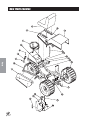
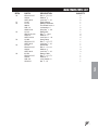
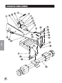
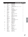
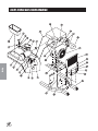
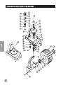
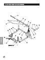
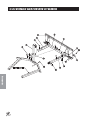
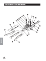
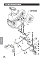
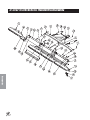
1
PARTS & SERVICE
MANUAL
SUPER RAKE 2 WHEEL DRIVE
Model 13-551-C Bunker Rake
SUPER RAKE 3 WHEEL DRIVE
Model 13-550-C Bunker Rake
Starting Serial #1080 (2WD)
Starting Serial #6201 (3WD)
January, 1999
SMITHCO PRODUCT SUPPORT
1-800-891-9435
Hwy SS and Poplar Avenue, Cameron WI 54822
E-mail: [email protected]
CONTENTS
Introduction
Introduction ........................................ 1-10
Service
Introduction ....................................................... 1
Symbols ........................................................ 2-3
Safe Practices .................................................. 4
Safety Precautions ........................................... 5
Specifications ................................................ 6-7
Optional Equipment .......................................... 7
Setup ................................................................ 8
Controls & Instruments ..................................... 9
Operation ........................................................ 10
Service .............................................. 11-17
Maintenance .............................................. 11-13
Service Chart .................................................. 14
End User’s Service Chart ............................... 15
Adjustments .............................................. 16-17
Storage ........................................................... 17
Diagrams
Diagrams ........................................... 18-23
Wiring Diagram ......................................... 18-19
Hydraulic Diagram .................................... 20-21
Wiring Schematic .................................................... 22
Hydraulic Schematic ................................................ 23
Parts .................................................. 24-57
Parts
Accessories
Main Frame ..............................................
Accelerator Linkage ..................................
Right Fender and Engine ..........................
Left Fender and Tank ................................
Console ....................................................
Two Wheel Drive Front Fork .....................
Three Wheel Drive Front Fork ..................
Engine and Pump .....................................
Rear Axle ..................................................
Hydraulic Oil Filter ....................................
Hydraulic Oil Tank .....................................
Rear Rake Lift ...........................................
On-Off Valve .............................................
Hydraulic Valve .........................................
13-110 Variable Pump ..............................
24-27
28-29
30-31
32-33
34-35
36-37
38-39
40-41
42-43
44-45
44-45
46-47
48-49
50-51
52-53
13-032 Front Wheel Motor (4.9 C.I.) ......... 54-55
13-615 Rear Wheel Motor (7.5 C.I.) ......... 56-57
Accessories .................................... 58-113
13-505 Lift Assembly ................................ 58-59
13-395 Front Mount Fan Rake ................. 60-61
13-413 Hydraulic Sand Plow with Lift ....... 62-65
13-355 Hydraulic 3-Bank Valve ................ 66-67
13-644 Sand Plow .................................... 68-71
13-107 Infield Scarifier ............................. 72-73
13-116 Weed Cultivator ............................ 74-75
13-199 Edger Kit ....................................... 76-77
13-577 Scarifier Vertical Blades ............... 78-79
13-111 Drag Mat Kit .................................. 80-81
42-026 84” SS Tournament Rake ............ 82-85
42-130 84” Steel Tournament Rake ......... 86-89
42-128 72” SS Tournament Rake ............ 90-93
42-132 72” Steel Tournament Rake ......... 94-97
13-438 Rake Assembly ............................ 98-99
13-606 Rake Assembly ........................ 100-101
13-319 Fan Rake Kit ............................. 102-103
13-298 Fan Rake Attachment ............... 102-103
13-319 Fan Rake Kit ............................ 102-103
26-007 Professional Infield Finisher ..... 104-105
26-008 Flex Action Field Finisher ......... 106-109
34-191 Box Grader ................................ 110-113
34-190 Spiker ........................................ 114-117
Reference ...................................... 118-120
EC Declaration of Conformity ....................... 118
Decal List ...................................................... 119
Quick Reference Replacement Parts ........... 120
Warranty ............................... Inside Back Cover
Reference
Thank you for purchasing a
Introduction
INTRODUCTION
product.
Read this manual and all other manuals pertaining to the Super Rake carefully as they have safety, operating,
assembly and maintenance instructions. Failure to do so could result in personal injury or equipment damage.
Keep manuals in a safe place after operator and maintenance personnel have read them. Right and left sides
are from the operator’s seat, facing forward.
All
machines have a Serial Number and Model Number. Both numbers are needed when ordering
parts. The serial number plate on the Super Rake is located on the right side main frame. Refer to engine
manual for placement of engine serial number.
For easy access record your Serial and Model numbers here.
Information needed when ordering replacement parts:
1. Model Number of machine
2. Serial Number of machine
3. Name and Part Number of part
4. Quantity of parts
1
SYMBOLS
Introduction
Read
Operator’s
Manual
2
Electrical Power
No Electrical
Power
Engine - Stop
Engine - Start
Engine - Run
Engine Oil
Temperature
Light
Water
Temperature
RPM
Gasoline
Diesel
Glow Plug - On
Glow Plug - Off
Glow Plug
Hour Meter
Hour Meter
Hand Throttle
Choke - Closed
Choke - Open
Park Brake
Park Brake
Release
Hydraulic Oil
Level
Fuse
H
R
Up/Down Arrow
Down/Lower
Up/Raise
No Smoking
Moving Parts
Manual
Operation
Pinch Point
Step
Hot Surface
Hydraulic Fluid
Penetration
Lift Arm
Tractor
Engage
Disengage
PTO
Ground Speed
Fast
Slow
High
Reverse
L
N
Low
Neutral
F
Introduction
SYMBOLS
Forward
Warning
Danger
Caution
3
SAFE PRACTICES
Introduction
1. It is your responsibility to read this manual and all publications associated with this machine (engine,
accessories and attachments).
2. Never allow anyone to operate or service the machine or its attachments without proper training and
instructions. Never allow minors to operate any equipment.
3. Learn the proper use of the machine, the location and purpose of all the controls and gauges before you
operate the equipment. Working with unfamiliar equipment can lead to accidents.
4. Wear all the necessary protective clothing and personal safety devises to protect your head, eyes, ears,
hands and feet. Operate the machine only in daylight or in good artificial light.
5. Inspect the area where the equipment will be used. Pick up all debris you can find before operating.
Beware of overhead obstructions and underground obstacles. Stay alert for hidden hazards.
6. Never operate equipment that is not in perfect working order or without decals, guards, shields, or other
protective devices in place.
7. Never disconnect or bypass any switch.
8. Carbon monoxide in the exhaust fumes can be fatal when inhaled, never operate a machine without
proper ventilation.
9. Fuel is highly flammable, handle with care.
10. Keep engine clean. Allow the engine to cool before storing and always remove the ignition key.
11. After engine has started, machine must not move. If movement is evident, the neutral mechanism is not
adjusted correctly. Shut engine off and readjust so the machine does not move when in neutral position.
13. Never use your hands to search for oil leaks. Hydraulic fluid under pressure can penetrate the skin and
cause serious injury.
14. This machine demands your attention. To prevent loss of control or tipping of the vehicle:
A. Use extra caution in backing up the vehicle. Ensure area is clear.
B. Do not stop or start suddenly on any slope.
C. Reduce speed on slopes and in sharp turns. Use caution when changing directions on slopes.
D. Stay alert for holes in the terrain and other hidden hazards.
15. Before leaving operator’s position for any reason:
A. Disengage all drives.
B. Lower all attachments to the ground.
C. Set park brake.
D. Shut engine off and remove the ignition key.
16. Keep hands, feet and clothing away from moving parts. Wait for all movement to stop before you clean,
adjust or service the machine.
17. Keep the area of operation clear of all bystanders.
18. Never carry passengers.
19. Stop engine before making repairs/adjustments or checking/adding oil to the crankcase.
20. Use parts and materials supplied by SMITHCO only. Do not modify any function or part.
These machines are intended for professional maintenance on golf courses and baseball fields. Other use is
forbidden.
4
Banding is under tension.
Connecting battery cables to the wrong post could result in personal injury and/or damage to
electrical system. Make sure battery and cables do not interfere or rub on any moving part.
Connect red positive (+) cable (A) to battery first. When disconnecting remove black negative
(-) cable (B) first.
Gasoline is flammable. Caution must be used when storing or handling it. Do not fill fuel tank
while engine is running or in an enclosed area. Fumes are explosive and dangerous to inhale.
DO NOT SMOKE while filling fuel tank. DO NOT OVERFILL.
Disengage front wheel drive for transport and plow operation only. Three to two wheel drive
can be shifted on the fly. Two wheel drive increases ground speed.
Quick removal of foot from forward or reverse pedal will result in an abrupt stop of machine.
Before servicing or making adjustments to machine, stop engine and remove key from
ignition.
Follow all procedures and ONLY use parts prescribed by the manufacturer. Read the engine
manual before maintenance.
Do not use petroleum solvents, eg., kerosene, which will cause cartridge to deteriorate. Do
not use pressurized air to clean cartridge. Pressurized air can damage cartridge.
Battery Electrolyte is an acidic solution and should be handled with care. If electrolyte is
splashed on any part of your body, flush all contact areas immediately with liberal amounts of
water. Get medical attention immediately.
Use of booster battery and jumper cables. Particular care should be used when connecting a
booster battery. Use proper polarity in order to prevent sparks.
5
Introduction
SAFETY PRECAUTIONS
SPECIFICATIONS
Introduction
WEIGHTS AND DIMENSIONS
Length with Rake
Length with out Rake
Width with Rake
Width with out Rake
Height
Wheel Base
Ground Clearance
Turning Radius
Crated Weight
85" (216cm)
68" (173cm)
73.5" (187cm)
58" (147cm)
44" (112cm)
47" (119cm)
7" (18cm)
10" (25cm) Inside Back Tires
990 lbs (449kg)
SOUND LEVEL (DBA) AT 3200 RPM
At ear level
At 3 ft (0.914 m)
At 30 ft (9.14 m)
84 dba
89 dba
74 dba
ENGINE
Make
Model#
Type / Spec#
Code
Horsepower
Torque
Fuel Pump
Fuel
Air Cleaner
Cooling System
Displacement
Bore & Stroke
Governor
Lubrication System
Valve Clearance
Ignition Type
Idle Speed
Maximum Speed
Briggs and Stratton Vanguard
303447
1018A2
95110111
16 Hp (12 Kw)
24.3 ft/lb at 2400 RPM
Vacuum Operated
Unleaded 85 Octane Gasoline Minimum
Dual Element on Engine
Remote Replaceable Element Mounted on Fender
Air Cooled
29.3 CID (480cc)
2.68" x 2.60" (68mm x 66mm)
Mechanical
Pressure type
Cold, Intake and Exhaust Lash 0.004" - 0.006" (0.10mm - 0.15mm)
Magnetron®
1200 RPM
3600 RPM
WHEELS & TIRE
PARK BRAKE
(3) 21 x 11.00 x 8 NHS 5 psi (0.35bar)
Hand Operated Lever
FRAME CONSTRUCTION
Welded Structural Steel Tubing
HYDRAULIC SYSTEM
Pump
Filter
Grade of Fluid
DRIVE
Sunstrand Hydrostatic Pump
10 Micron
SAE 10W-40 API Service SG Motor Oil
Hydrostatic Pump to Wheel Motors
Two or Three Wheel Drive (Switchable)
HYDRAULIC DRIVE WHEEL MOTOR
Front
Rear
6
Parker (4.9 cu/in (80cc) Fixed Displacement)(Three wheel drive ONLY)
Parker (7.8 cu/in (128cc) Fixed Displacement)
SPEED
Forward Speed
Reverse Speed
0 to 10 mph (0-16 kph)
0 to 4 mph (0-6 kph)
DRIVE CONTROL
Foot control, 2 pedals, Forward and Reverse, Also controls engine speed
STEERING
Front Wheel, 15" (38cm) - Steering Wheel, 7:1 reduction ratio
ELECTRICAL SYSTEM
12 volt, 16 Amp alternator, Negative ground, Electric start
BATTERY (Not Included)
BCI Group
Cold Cranking Amps
Ground Terminal Polarity
Maximum Length
Maximum Width
Maximum Height
Automotive type 45-12 volt
Size 45
480
Negative (-)
9" (23cm)
5.38" (14cm)
9" (23cm)
SEAT
Adjustable position deluxe seat with back support
FLUID CAPACITY
Crankcase Oil
Fuel
Hydraulic Fluid
Introduction
SPECIFICATIONS (CONTINUED)
Approximately 1.5 quart (1.4 liters) without filter
Approximately 1.75 quart (1.7 liters) with filter
15.6 quart (14.8 liters)
12.9 quart (12.2 liters)
OPTIONAL EQUIPMENT
13-505 Attachment Lift (13-551 Only)
26-007 Professional Infield Finisher
13-395 Front Mount Fan Rake
26-008 Flex Action Field Finisher
13-413 Front Mounted Sand Plow
34-191 Box Grader
13-355 3-Bank Valve (used with 13-412)
34-190 Spiker
13-644 Sand Plow
42-502 Green Star Spiker Reel Set (3)
13-107* Infield Scarifier
42-503 RBS Mount for Smithco Super Rake
13-116* Weed Cultivator
42-512 Green Star Roller Set (3)
13-199* Edger Kit
42-513 Green Star Brush Set (3)
13-577* Scarifier, Vertical Blades
42-520 Green Star RBS Main Frame
13-111 Drag Mat Kit
42-530 22-11.00 x 8 Turf Track R/S Tire
13-438 Rake Assembly
42-531 22-11.00 x 8 Custom Smooth Tread Tire
13-606 Rake Assembly with Lexan Blades
42-550 Green Star Total RBS System
13-319 Fan Rake Kit
13-298 Fan Rake Attachment
*
Must have 13-505 Lift Assembly installed before installation (13-551 Only).
7
SETUP
Introduction
The Super Rake arrives from
with some assembly required before service.
1. Remove top and sides from shipping crate. Remove metal banding from machine. Remove seat, steering
wheel and anything els in create.
Banding is under tension.
2. Set park brake. Park brake is located on left side of console.
Push brake lever forward and park brake is engaged.
3. Rear wheel mounting. Block front tire. Jack up rear of
machine being careful not to damage underside of machine.
Place wheel on hub lining up bolt holes. Use ten lug bolts
provided. Then torque to 64 - 74 ft/lb (87-100Nm) using a
cross pattern. Retorque after first 10 hours and every 200
hours thereafter. Lower machine to ground and remove
blocks and jack.
4. Install steering wheel (Ref#1) on machine. Place steering
wheel on shaft (Ref#3). Line up holes and insert 1/4 x 2" Roll
Pin (Ref#2) into wheel and shaft. Tighten set screw.
5. Check tire pressure. Rear tire pressure should be 5 psi
(0.35bar). Front tire is fluid filled only on 2WD.
6. Battery not furnished. Install an automotive type 45 -12 volt;
300 cold cranking amps (minimum) battery in battery box
located under the seat. Battery should be in battery box with
posts to right with positive to rear. This is a negative grounding system. Attach battery hold-downs. Then attach red
positive (+) cable (A) to positive terminal. Slide rubber boot
over positive terminal to prevent shorts. Attach black negative
(-) cable (B) to negative terminal.
Connecting battery cables to the wrong post could result in personal injury and/or damage to
electrical system. Make sure battery and cables do not interfere or rub on any moving part.
Connect red positive (+) cable (A) to battery first. When disconnecting remove black negative
(-) cable (B) first.
7. Check engine oil and add as necessary. Dip stick is located on back left side of engine. Oil fill is located
on left valve cover, see engine manual for recommended motor oil. DO NOT OVERFILL.
8. Fill fuel tank, located on left rear of machine, with Unleaded 87 Octane gasoline (minimum).
Gasoline is flammable. Caution must be used when storing or handling it. Do not fill fuel tank
while engine is running or in an enclosed area. Fumes are explosive and dangerous to inhale.
DO NOT SMOKE while filling fuel tank. DO NOT OVERFILL.
9. Check hydraulic oil level in right side tank. The level should be 2" to 21/2" from top of fill neck when fluid is
cold. If level is low, add SAE 10W-40 API Service SG motor oil.
10. Machine should be greased before starting. Refer to Lubrication under Maintenance for locations.
11. Read operating instructions before starting machine.
8
Introduction
CONTROLS & INSTRUMENTS
INSTUMENT PANEL
Located on right fender.
A. Ignition Switch: Located on front of the right fender.
B. Two Or Three Wheel Drive: Front wheel drive valve is located on
front right fender. Push to engage front wheel drive and pull to disengage front wheel drive.
Disengage front wheel drive for transport and plow operation only. Three to two wheel drive can be shifted on the
fly. Two wheel drive increases ground speed.
C. Ammeter: The ammeter indicates the rate of charging or discharging
of batttery.
D. Fuse Holder and Fuse: Located in center on right side of instrument
panel. A 30 Amp fuse is used.
E. Oil Light: The oil light should come on when ignition is on, without
engine running. The oil light will light when the oil pressure is low. If oil
light should come on, shut off engine immediately and find cause.
F.
Hour Meter: The hour meter indicates hours of machine operation.
The hour meter operates when ignition switch is on.
G. Choke: Choke is located in center of instrument panel. Pull choke to rear
to close choke plate when starting a cold engine. A warm engine may not
require "choking" to start.
H. Hand Throttle: Hand throttle is located on left side of instument panel. Use
it to regulate engine speed.
RIGHT FLOORBOARD
Two Pedal Foot Control: Foot Pedal controls forward and reverse motion and
also acts as a brake. Pushing down on front pedal (I) will give you a forward
motion and pushing down on rear pedal (J) will give you a reverse motion.
When pedal is released the hydrostatic transmission centers and stops the
vehicle with a braking action. Ground speed is proportional to how far the foot
pedal is depressed. (K) is the Hand Lift for the Sand Plow.
Quick removal of foot from forward or reverse pedal will result
in an abrupt stop of machine.
VALVE PANEL
The Lift Levers are located on left fender. To raise pull back and to lower push
forward. Release the lever when attachment is in proper position and lever will
return too neutral. The Rake Lift lever (L) is on the outside of the machine. The
Lift Assembly lever (M) is on the inside closest to the seat unless equipped with
a hydraulic plow then the plow lever is closest to the seat.
STEERING
Acquaint yourself with steering before operating machine. The automotive type steering wheel is connected to
the front wheel assembly by a chain driven sprocket. This allows for quick turns and short turning radius.
SEAT ADJUSTMENT
Seat Adjustment Lever is located under front of seat on left side. It allows seat adjustment forward or backward
for operator’s comfort. There are four different bolt patterns so that you can manually adjust seat to fit
operator’s comfort.
PARK BRAKE
Park brake is located on left side of steering console. Push lever forward to set brake and pull lever rearward to
release brake. Park brake must be applied to start trap rake.
9
OPERATION
Introduction
STARTING ENGINE
Before operating this machine, become familiar with all controls and
functions of these units. Also complete all maintenance requirements
and read all safety warnings. By knowing the machine thoroughly, how
it operates and by doing the prescribed maintenance steps, you can
expect relatively trouble-free operation for years to come.
1. Make sure the fuel flow valve, located on the fuel tank, is “ON.”
2. Set park brake. Start safety switch is on the park brake.
3. The ignition switch is located on right fender. Insert key (A) and
turn clockwise until engine starts (C). Release key and it will
return to run position (B). Use choke and hand throttle as necessary.
4. Allow engine to idle and warm up a few minutes before selecting a direction of travel.
HOW TO RAKE A SAND TRAP
View bunker to determine the most efficient pattern to follow so that rake pattern and configuration of bunker will
flow in same general direction and look attractive.
Enter bunker at its lowest point. Perhaps drain area or another point where “lip” of the trap is minimal.
Hydraulic drive tractors engine speed should open at 75% - 100% of maximum order
to insure proper hydraulic system performance and maximum engine cooling.
Operate at 2-4 mph (3-6.5 kph) for best raking results. Control speed with
hydraulic pedal.
Once fully inside bunker, lower
rear rake and proceed
forward as described
above.
First pass should be
directly down center
of trap. This helps
avoid extremely sharp
turns that will spoil sands’ appearance. Once at far end, turn
machine and drive down one side of trap
and come back up other side.
Grass or other material may build up on rake tines as machine passes “enter/exit” point. Lift rake briefly while
still moving forward.
Do not rake closer than 6" (15cm) to edge of trap.
Do not rake slopes in trap. The weight of machine will pull sand down.
Use cultivator or other center mounted accessories only as necessary for compacted sand. Frequent use will
leave sand too soft and objectionable to some golfers.
Use front mounted plow to push sand to desired locations within trap.
After exiting trap, secure machines in accordance with practices described in this manual. Rake trap edges,
slopes and “enter /exit” area with a hand rake.
After returning to maintenance area, thoroughly clean machine, check fluids, and lubricate as advised in this
manual.
10
MAINTENANCE
Before servicing or making adjustments to machine, stop engine and remove key from ignition.
Use all procedures and parts prescribed by the manufacturer's. Read the engine manual
before operation.
The suggested maintenance checklist is not offered as a replacement for the manufacturer’s but as a supplement. You must adhere to guidelines established by manufacturer for warranty coverage. In adverse conditions
such as dirt, mud or extreme temperatures, maintenance should be more frequent.
Service
DAILY CHECKLIST
1. Check park brake adjustment. Adjust as required.
2. Check engine oil level. Add as needed. DO NOT OVERFILL.
3. Rear tire pressure should be 5 psi (0.35bar) maximum. Front tire is fluid filled only on the 2WD.
4. Inspect electrical system for loose connections or frayed wiring, including battery cables. Replace any
faulty equipment or tighten if loose.
5. Check hardware for loose or missing nuts, bolts, screws, etc., and tighten or replace as needed.
6. Inspect hydraulic lines for damage or leaks. Never use hands to inspect leaks.
7. Check hydraulic oil level in right side tank. The level should be 2" to 21/2" from top of fill neck when fluid is
cold. If level is low, add SAE 10W-40 API Service SG motor oil.
8. Change hydraulic oil filter after first 20 hours then at 100 hours, then every 250 hours thereafter.
9. Inspect steering, throttle and shift linkages for good hookups and clear travel.
10. Check anti-vibration mounts on engine frame.
11. Check controls for smooth, proper working operation. Lubricate as needed.
LUBRICATION
Use No. 2 General purpose Lithium Base Grease and lubricate every 100 hours. The Super Rake has one
grease fitting located in bearing on steering shaft.
AIR CLEANER ON ENGINE
1. Unhook clips on both sides of cover and remove cover.
2. Carefully slide pre-cleaner off cartridge.
To service pre-cleaner, wash in liquid detergent and water. Squeeze dry in a clean cloth. Saturate in
engine oil. Squeeze in clean, absorbent cloth to remove all excess oil. Replace if very dirty or damaged.
3. Remove knob and plate. Carefully remove cartridge to prevent debris from entering carburetor. To service
cartridge, clean by tapping gently on flat surface. Do not oil cartridge. Replace if very dirty or damaged.
Do not use petroleum solvents, eg., kerosene, which will cause cartridge to deteriorate. Do
not use pressurized air to clean cartridge. Pressurized air can damage cartridge.
4. Reinstall cartridge, plate and knob.
5. Reassemble pre-cleaner on cartridge.
6. Replace cover and reattach clips to body.
AIR CLEANER ON FENDER
1. Remove end cap and filter element, clean by tapping gently on flat surface. Do not oil cartridge. Replace
if very dirty or damaged.
2. Remove air clearner cap and clean. Cap can be washed in solvent, make sure its dry before reinstalling.
11
MAINTENANCE
TIRE PRESSURE
Caution must be used when inflating a low tire to recommended pressure. Over inflating can cause tires to
explode. Tires should be 5 psi (0.35bar). Improper inflation will reduce tire life considerably.
ENGINE OIL
Change and add oil according to chart below. Do not overfill. Use a high quality detergent oil classified "For
Service SE, SF, SG" SAE 30 oil. Use no special additives with recommended oils. Do not mix oil with gasoline.
SAE Viscosity Grades
Service
Starting Temperature Range Anticipated Before Next Oil Change
Air cooled engine run hotter than automotive engines. Use of multi-viscosity oils (10W-30, etc) above 40° F
(4° C) will result in high oil consumption and possible engine damage. Check oil level more frequently if using
these types of oils.
SAE 30 oil, if used below 40° F (4° C), will result in hard starting and possible engine bore damage due to inadequate lubrication.
HYDRAULIC OIL
1. Use SAE 10W-40 API Service SG/SH/CD/EC-11 motor oil.
2. For proper warranty, change oil every 500 hours or annually, which ever is first and change filter after
the first 20 hours, then at 100 hours, then every 250 hours thereafter.
3. The oil level should be 2" to 21/2" from top of fill neck when fluid is cold. Do not overfill.
4. After changing oil and/or filter, run the machine for a few minutes. Check oil level and for leaks.
5. Always use caution when filling hydraulic oil tank or checking level to keep system free of contaminants.
Check and service more frequently when operating in extremely cold, hot or dusty conditions.
6. If natural color of fluid is now black or smells burnt, it is possible that an overheating problem exists.
7. If fluid becomes milky, water contamination may be a problem.
8. If either of the above conditions happen, change oil and filter immediately after fluid is cool and find
cause. Take fluid level readings when system is cold.
9. In extreme temperatures you can use straight weight oil. We recommend SAE 30W API Service SG
when hot (above 90°F (33°C)) and SAE 10W API Service SG when cold (below 32°F (0°C) ambient
temperature. Use either motor oil or hydraulic oil, but do not mix.
10. Oil being added to the system must be the same as what is already in the tank. Mark tank fill area as to
which type you put in.
TOWING
When it is necessary to move the Super Rake without engine running, by-pass valve built into hydrostatic pump
must be "open" by truning it counter-clockwise. The valve is located on bottom left of pump. An "open" valve
allows fluid to pass through the wheels freely.When normal, driven, operation is desired, valve should be "closed
by turning it clockwise. Failure to "close" the valve with engine running means no power to wheels.
12
MAINTENANCE
WHEEL MOUNTING PROCEDURE
1. Set park brake. Turn machine off and remove key.
2. Block one of the other wheels.
3. Loosen nuts slightly on wheel to be removed.
4. Jack up machine being careful not to damage underside of machine.
5. Remove nuts, remove Wheel.
6. Torque nuts to 64-74 ft/lb (87-100Nm) using a cross pattern. Retorque after first 10 hours and every 200
hours thereafter.
7. Lower machine to ground and remove blocks and jack.
BATTERY
Batteries normally produce explosive gases which can cause personal injury. Do not allow flames, sparks or
any ignited object to come near the battery. When charging or working near battery, always shield your eyes
and always provide proper ventilation.
Battery cable should be disconnected before using "Fast Charge".
Charge battery at 15 amps for 10 minutes or 7 amps for 30 minutes. Do not exceed the recommended charging
rate. If electrolyte starts boiling over, decrease charging.
Always remove grounded (-) battery clamp first and replace it last. Avoid hazards by:
1. Filling batteries in well-ventilated areas.
2. Wear eye protection and rubber gloves.
3. Avoid breathing fumes when electrolyte is added.
4. Avoid spilling or dripping electrolyte.
Battery Electrolyte is an acidic solution and should be handled with care. If electrolyte is
splashed on any part of your body, flush all contact areas immediately with liberal amounts of
water. Get medical attention immediately.
JUMP STARTING
Use of booster battery and jumper cables. Particular care should be used when connecting a
booster battery. Use proper polarity in order to prevent sparks.
To jump start (negative grounded battery):
1. Shield eyes.
2. Connect ends of one cable to positive (+)
terminals of each battery, first (A) then (B).
3. Connect one end of other cable to negative (-)
terminal of "good" battery (C).
4. Connect other end of cable (D) to engine block
on unit being started (NOT to negative (-) terminal
of battery)
To prevent damage to other electrical components on unit being started, make certain that engine is at idle
speed before disconnecting jumper cables.
13
Service
5. Place new wheel on hub lining up bolt holes.
SERVICE CHART
Before servicing or making adjustments to the machine, stop engine, set park break, block
wheels and remove key from ignition.
C
C
400 Hours
R
R
R
R
C
C
C
300 Hours
C
R
R
C
C
C
250 Hours
R
200 Hours
As Required
C
100 Hours
Daily
Service
¤£ Engine Oil (Change every 50 hours)
¤ Engine Oil Filter
Engine for Leaks and Loose Parts
‡ Air Cleaner, Engine and Fender Mounted
‡ Air Cleaner Pre-Cleaner
Spark Plugs
Valve Clearance
Idle Speed
Air Cooling System
Hoses
* Tire Pressure
Visual Inspection of Tires
Fuel Level
Fuel Filter
Hydraulic Oil
† Hydraulic Oil Filter
Hydraulic System for Leaks and Loose Parts
Battery Electrolyte Level
Clean Battery Terminals
§ Torque Lug Nuts
Lubricate
R
R
R
C
C
C
R
R
C
C
C
C
C
C
C
C
C
C
C
C
C
C
C
C
C
C
C
C
C
C
C
C
C
C
C
C
C
C
C
C
C
C
C
C
C
C
C
C
C
C
R
R
C
Every 500 Hours/Yearly
Follow all procedures and ONLY use parts prescribed by the manufacturer. Read the engine
manual before maintenance.
R
R
C
R
R
R
C
C
C
C
C
C
R
R
R
C
C
C
C
C
C=Check or Clean at specified intervals
R=Replace at specified intervals
* Tire pressure: 5 psi (0.35 bar)
† Replace hydraulic filters after the first 20, 100, and every 250 there after.
§ Torque tire nuts after the first 10 hours and every 200 hours there after (64 to 74 ft/lb (87-100Nm))
¤ Change Oil and Filter after first 8 hours.
£ Change oil every 25 hours when operating under heavy load or in high ambient temperatures.
‡ Clean more often under dusty conditions or when airborne debris is present , replace air cleaner parts, if very dirty.
The suggested maintenance checklist is not offered as a replacement for the manufacturer’s engine manual but
as a supplement. You must adhere to the guidelines established by the manufacturer for warranty coverage. In
adverse conditions such as dirt, mud or extreme temperatures, maintenance should be more frequent.
14
¤£Engine Oil (Change every 50 hours)
¤ Engine Oil Filter
Engine for Leaks and Loose Parts
‡Air Cleaner (Paper Element)+A18+A18
‡Pre-Cleaner (Every 25 hours)
Spark Plugs
Valve Clearance
Idle Speed
Air Cooling System
Hoses
*Tire Pressure
Visual Inspection of Tires
Fuel Level
Fuel Filter
†Hydraulic Oil
Hydraulic System for Leaks and Loose Parts
Battery Electrolyte Level
Clean Battery Terminals
§Torque Lug Nuts
Lubricate
C=Check or Clean at specified intervals
R=Replace at specified intervals
* Tire pressure: 5 psi (0.35 bar)
† Replace hydraulic filters after the first 20, 100, and every 250 there after.
§ Torque tire nuts after the first 10 hours and every 200 hours there after (64 to 74 ft/lb (87-100Nm))
¤ Change Oil and Filter after first 8 hours.
£ Change oil every 25 hours when operating under heavy load or in high ambient temperatures.
‡ Clean more often under dusty conditions or when airborne debris is present , replace air cleaner parts, if very dirty.
15
Service
Every 500 Hours/Yearly
250 Hours
200 Hours
100 Hours
50 Hours
25 Hours
As Required
Daily
END USER’S SERVICE CHART
ADJUSTMENTS
RAKE LIFT CYLINDER
Completely lower Rake Lift. Remove cotter pin (A)
and clevis pin (B). Place attachment lift arms (C) at 1/16"
above cross member (D) on Rake Lift. Loosen jam nut (E).
Twist cylinder extension (F) so clevis pin end of cylinder extension lines up with holes in attachment lift arm. Replace clevis
and cotter pins. Tighten jam nut. Raise and lower Rake Lift to check
for proper clearance.
Service
PARK BRAKE
By turning knob on end of lever you can tighten or loosen brake a small amount. Make all adjustments on knob.
Adjusting yokes will result incable kinking.
STEERING CHAIN
Steering sprockets (K) should be level with each other, check with straight edge.
Make any adjustments. Slide idler pulley (J) so that it is snug onto the chain.
Tighten all nuts and bolts in place.
LIFT ASSEMBLY
When it is necessary to have attachment lift dig deeper or lower into
ground, relocate cylinder rod of hydraulic cylinder which controls
the lift distances, into lower set of holes in attachment lift swing
arm. This new position forces attachment farther down.
WHEEL ‘CREEP’ ADJUSTMENT
‘Creep’ is when engine is running and hydrostatic transmission is in
neutral, but due to inadequate alignment wheels still move. Do the following procedures to stop this motion.
1. Lift up and support machine so all wheels are off the ground and
can turn freely.
2. At rear of machine, on the bottom of the hydrostatic transmission
is the shift arm (A). Loosen bolts (B).
3. With engine running move stop (C) so it moves shift arm (A) to
center and wheel creep stops.
4. Tighten all fasteners and test by using foot pedal linkage to see
that the "creep" is removed.
5. Turn engine off and lower machine.
16
ADJUSTMENTS
Service
SPEED BOSS
Speed Boss allows the machine to operate at
a proper speed while raking bunkers on golf
courses. This speed has been factory set at
an average speed of 3-4 MPH(5-6.5 kph).
The Speed Boss will only limit the speed while
the rake is in lowerered into the operating
position. The speed setting may be adjusted
by removing the ball joint(A) from the limiting
arm(B). Then loosen jam nut(C). Turn ball
joint clockwise to make the machine operate
faster or turn counter clockwise to go slower.
Tighten jam nut. Connect ball joint to limiting
arm. Check to make sure nothing is binding
and test drive to check desired speed.
When the rear rake attachment is lowered while the machine is in forward position, the
forward speed of the machine will slow drastically. Operator should be prepared for rapid
change in speed.
STORAGE
Engines stored over 30 days need to be protected or drained of fuel to prevent gum from forming in a fuel system or on essential carburetor parts.
1. For engine protection, we recommend use of Briggs and Stratton Gasoline Additive, Part Number 5041,
or a comparable gasoline additive. Mix Additive with fuel in fuel tank or storage container. Run engine for
a short time to circulate additive through carburetor. Engine and fuel can be store up to 24 months. Your
Service Dealer has single-use pouches of Gasoline Additive available.
2. If engine is still warm, drain oil from crankcase. Refill with fresh oil of recommended grade.
3. Remove spark plugs and pour about 1 oz (3ml) of engine oil into cylinders. Replace spark plugs and
crank slowly to distribute oil.
4. Clean dirt and chaff from cylinders, cylinder head fins, blower housing, rotating screen and muffler area.
5. Store in a clean and dry area, but NOT near a stove, furnace or water heater which uses a pilot light or
any device that can create a spark.
17
WIRING DIAGRAM
Color Code Chart
Bl
Br
Y
Grn
O
R
B
P
W
Diagrams
18
Blue
Brown
Yellow
Green
Orange
Red
Black
Purple
White
WIRING DIAGRAM
PART#
DESCRIPTION
1
2
12-017
50-360
22-071
13-050
50-359
8862
22-002
13-488
13-491
13-641
Hour Meter
Fuse Holder
Fuse 30 AMP
Purple Wire (fuse to ammeter)
After Fire Solenoid (on engine)
Rectifier (on engine)
Ammeter
Stop Switch Terminal (on engine)
Battery Cable, Black
Battery, automotive type 45-12V; 300 cold cranking
AMPS minimum (53/8" wide x 9" high x 9" long)
Battery Cable, Red
Battery Boot
Solenoid (B & S# 807829)
Starter Cable
Starter (on engine)
Oil Pressure Light
Coupler
Interlock Switch
Ignition Switch (B & S# 496603)
Oil Sender (on engine) (B & S# 491657)
Red Wire (ignition to hour meter)
22-017
13-497
Ground Cable from Engine to Solenoid Mount
Wire Harness
3
4
5
6
7
8
9
10
11
12
13
14
15
16
17
18
19
*
22-003
22-054
22-055
12-031
13-492
13-215
QUANTITY
1
1
1
1
1
1
1
1
1
1
1
1
1
1
1
1
1
1
1
1
1
Diagrams
REF#
1
19
HYDRAULIC DIAGRAM
Diagrams
HYDRAULIC PRESSURES
Pump Displacement
Pump Input Speed (up to)
Max. Operating Pressure
Charge Pump Displacement
Max. Inlet Vacuum
Max. Case Pressure
Implement Setting
Relief Valve Pressure (set at)
13-261 Hydraulic Valve (2 bank)
13-355 Hydraulic Valve (3 bank)
20
.913 in.3/ rev
3600 RPM
3500 PSI, 4500 Peek PSI
.33 in.3/ rev
5 in. Hg
25 PSI
700 - 1000 PSI
3600 PSI
700 PSI
700 PSI
HYDRAULIC DIAGRAM
PART#
DESCRIPTION
1
2
13-032
13-424
8840-62
13-425
8840-69
13-409
18-174
18-228
18-266
13-587
13-584
13-586
8810-11
18-077
13-616
8810-36
18-077
13-110
23-006
23-031
8917-11
18-077
18-184
13-617
13-615
13-612
23-172
13-633
18-264
18-164
13-292
13-357
13-552
13-549
76-105
13-261
13-262
13-355
13-484
60-368
13-406
13-444
Wheel Motor
Hydraulic Hose (631/4 long)
Flex Guard Loom
Hydraulic Hose (701/4 long)
Flex Guard Loom
On - Off Valve
Elbow 1/2 ST Thread
Hollow Hex Plug
Elbow 45°
Hydraulic Hose (16 long)
Oil Tank
Filler Breather
Hose 5/8
Hose Clamp
Hydraulic Hose (29 long)
Hose 5/8
Hose Clamp
Hydrostatic Pump
Oil Filter
Replacement Filter Only
Suction Hose 5/8
Hose Clamp
Hydraulic Hose (29 long)
Hydrauic Hose (25 long)
Wheel Motor
Hydraulic Tube
Oil Cooler
Hydraulic Hose (191/2 long)
Cap (2WD only)
Hydraulic Hose (16 long)
Hydraulic Cylinder
Hydraulic Cylinder
Hydaraulic Hose (211/4ong)
Hydraulic Hose (241/8 long)
Hydraulic Hose (171/2long)
Hydraulic Valve (2 bank)
Valve Handle Set (2 bank)
Hydraulic Valve (3 bank)
Valve Handle Kit (3 bank)
Hydraulic Hose (591/4long)
Hydraulic Cylinder
Hydraulic Hose (50 long)
3
4
5
6
7
8
9
10
11
12
13
14
15
16
17
18
19
20
21
22
23
24
25
26
27
28
QUANTITY
1
1
1
1
1
2
2
2
1
1
1
1
2
1
1
2
1
1
Diagrams
REF#
1
2
1
1
2
2
1
2
2
2
1
1
1
1
1
1
1
1
1
1
21
WIRING SCHEMATIC 2 WHEEL DRIVE
Diagrams
22
Diagrams
HYDRAULIC SCHEMATIC 2 WHEEL DRIVE
HYDRAULCI SCHEMATIC 3 WHEEL DRIVE
23
MAIN FRAME DRAWING
Parts
24
MAIN FRAME PARTS LIST
1
2
3
4
5
6
7
8
9
10
11
12
13
14
15
16
17
18
19
PART#
DESCRIPTION
13-419
13-422
HSD-14-100
13-418
HB-38-16-250
HW-38
HNTL-38-16
13-208
HB-38-16-350
HW-38
HNCL-38-16
13-035
HSD-14-100
20-057
20-129
13-010
HB-516-18-125
HW-516
HWL-516
HN-516-18
13-547
HW-516
HWL-516
HN-516-18
13-009
HB-516-18-125
HW-516
HWL-516
HN-516-18
13-596
78-024
HRS-316-050
13-570
13-569
26-034
HWL-516
HN-516-18
HB-516-18-200
HNTL-516-18
13-016
HB-516-18-100
HN-516-18
HW-516
HWL-516
13-631
13-610
11-005-01
13-610-02
60-268
13-118
13-623
HWL-12
HN-12-20
Left Floor Board
Left Rubber Mat
Drill Screw 14 x 1
Front Bumper
Bolt 3/8 - 16 x 21/2
Washer 3/8
Lock Nut 3/8 - 16
Bumper Brace
Bolt 3/8 - 16 x 31/2
Washer 3/8
Center Locknut 3/8 - 16
Console
DrilL Screw 1/4 x 1
Steering Wheel
Center Cap
Left Seat Bracket
Bolt 5/16 - 18 x 11/4
Washer 5/16
Lockwasher 5/16
Nut 5/16 - 18
Adjustable Seat
Washer 5/16
Lockwasher 5/16
Nut 5/16 - 18
Right Seat Bracket
Bolt 5/16 - 18 x 11/4
Washer 5/16
Lockwasher 5/16
Nut 5/16 - 18
Rear Hood, Orange
Draw Latch
Pop Rivet 3/16 x 1/2
Bracket
Gas Spring 60#
Ball Stud
Lockwasher 5/16
Nut 5/16 - 18
Bolt 5/16 - 18 x 2
Lock Nut 5/16 x 18
Seat Hinge
Bolt 5/16 - 18 x 1
Nut 5/16 - 18
Washer 5/16
Lockwasher 5/16
Main Frame
Tire and Wheel
Tire 21 x 11.00 x 8 Compass
Wheel
Lug Bolt 1/2 - 20 x 15/16
U-Bolt
Axle
Lockwasher 1/2
Nut 1/2 - 20
QUANTITY
1
1
3
1
2
2
2
2
2
2
2
1
4
1
1
1
1
1
1
1
1
4
4
4
1
1
1
1
1
1
2
6
1
1
2
2
2
2
2
1
2
2
4
2
1
2
2
2
10
2
1
4
4
Parts
REF#
25
MAIN FRAME DRAWING
Parts
26
MAIN FRAME PARTS LIST
20
21
22
23
24
25
26
PART#
DESCRIPTION
HB-38-16-125
HW-38
HNTL-38-16
13-637
13-214
8900-6
HWL-14
HNW-14-20
13-213
HB-516-18-100
HW-516
HNTL-516-18
13-099
HB-38-16-175
HNTL-38-16
13-218
HB-38-16-125
HW-38
HNTL-38-16
22-054
HB-38-16-125
HW-38
HWL-38
HN-38-16
Bolt 3/8 - 16 x 11/4
Washer 3/8
Lock Nut 3/8 - 16
Engine Mount
Battery Hold Down
Flex Guard Loom 1/4
Lockwasher 1/4
Wing Nut 1/4 - 20
Battery Box
Bolt 5/16 - 18 x 1
Washer 5/16
Lock Nut 5/16 - 18
Hose Clamp
Bolt 3/8 - 16 x 13/4
Lock Nut 3/8 - 16
Mud Guard
Bolt 3/8 - 16 x 11/4
Washer 3/8
Lock Nut 3/8 - 16
Battery Cable
Bolt 3/8 - 16 x 11/4
Washer 3/8
Lock Washer 3/8
Nut 3/8 - 16
QUANTITY
2
2
2
1
1
1
2
2
1
4
6
4
1
1
1
1
3
4
3
1
1
1
1
1
Parts
REF#
27
ACCELERATOR LINKAGE DRAWING
Parts
28
ACCELERATOR LINKAGE PARTS LIST
1
2
3
4
5
6
7
8
9
10
11
12
13
14
15
16
17
18
19
20
21
22
23
24
25
26
PART#
DESCRIPTION
13-420
13-421
HCP-516-100
11-100
13-526
13-499
HB-14-20-100
HWL-14
HN-14-20
HMB-12-14
13-510
13-515
HP-18-100
13-512
HP-18-100
HN-516-24
13-511
18-234
HP-18-100
34-038
18-234
13-624
HB-38-16-100
HW-38
HNTL-38-16
HRS-316-050
8946-1.5
13-625
8946-1.5
HRS-316-050
11-050
HRP-14-100
13-628
18-115
HWL-14
HN-14-28
13-623
11-021
HWL-38
HB-38-16-125
HW-38
HNTL-38-16
13-637
HN-38-24
13-632
HNJ-58-18
13-635
HB-14-20-075
HNTL-14-20
Right Floor Board
Right Rubber Mat
Clevis Pin 5/16 x 1
Linkage Yoke 5/16 - 24
Foot Pedal Assembly (Includes Ref# 2, 3, 5, 7 through11)
Grip
Bolt 1/4 - 20 x 1
Lockwasher 1/4
Nut 1/4 - 20
Machine Bushing 1/2 x 14GA
Foot Pedal Bracket
Forward/Reverse Decal
Cotter Pin 1/8 x 1
Linkage Rod
Cotter Pin 1/8 x 1
Nut 5/16 - 24
Reverse Pedal with Bushing
Bushing
Cotter Pin 1/8 x 1
Centering Arm with Bushing
Bushing
Stop with Plastic Wear Strip
Bolt 3/8 - 16 x 1
Washer 3/8
Lock Nut 3/8 - 16
Pop Rivet 3/16 x 1/2
Plastic Wear Strip
Shift Arm with Plastic Wear Strip
Plastic Wear Strip
Pop Rivet 3/16 x 1/2
Extension Spring
Roll Pin 1/4 x 1
Engine Frame
Ball Joint 1/4 - 28
Lockwasher 1/4
Nut 1/4 - 28
Axle
Rubber Engine Mount
Lockwasher 3/8
Bolt 3/8 - 16 x 11/4
Washer 3/8
Lock Nut 3/8 - 16
Engine Mount
Nut 3/8 - 24
Push-Pull Cable with Nuts
Jam Nut 5/8 - 18
Cable Bracket
Bolt 1/4 - 20 x 3/4
Lock Nut 1/4 - 20
QUANTITY
1
1
1
1
1
2
1
1
2
2
1
1
1
1
1
1
1
1
1
2
2
1
2
1
2
1
1
1
1
1
1
1
1
2
2
4
1
2
4
2
2
2
1
4
1
4
1
2
2
Parts
REF#
29
RIGHT FENDER AND ENGINE DRAWING
Parts
30
RIGHT FENDER AND ENGINE PARTS LIST
1
2
3
4
5
6
7
8
9
10
11
12
13
14
15
16
17
18
19
20
21
22
23
24
25
26
27
28
29
30
31
32
33
34
PART#
DESCRIPTION
13-488
13-409
13-539
13-566
13-640
HSA-8-075
22-003
12-017
11-130
11-131
13-593
15-013
13-583
50-081
HW-14
HN-14-20
13-416
11-132
HB-14-20-075
HWL-14
HN-14-20
11-133
18-123
34-160
34-162
HSM-10-32-063
HWL-10
HN-10-32
HST-14-20-075
HWL-14
HN-14-20
34-163
HN-38-24
21-161
27-113
27-115
18-116
13-609
15-165
15-165-01
13-531
13-518
13-491
23-172
18-015
13-004
HMB-916-14
23-140
HB-716-14-175
HNCL-716-14
Ignition Key with Switch
On-Off Valve 3WD to 2WD
Choke Control with Cable
Instrument Panel
Instrument Panel Decal
Tapping Screw #8 x 3/4
Ammeter
Hour Meter
Air Cleaner with Element
Filter Element (Replacement)
Right Fender, Orange
Rubber Bumper
Trash Bucket
Rubber Insulator
Lockwasher 1/4
Nut 1/4 - 20
Right Hood Support
Mounting Band
Bolt 1/4 - 20 x 3/4
Lockwasher 1/4
Nut 1/4 - 20
Air Inlet Cap
Hose Clamp #32 19/16 - 21/2
Throttle Control with Cable
Throttle Bracket
Machine Screw #10 - 32 x 5/8
Lockwasher #10
Nut #10 - 32
Truss Machine Screw 1/4 - 20 x 3/4
Lockwasher 1/4
Nut 1/4 - 20
Cable Bracket
Nut 3/8 - 24
Wire Block
Rubber Elbow
Tube
Hose Clamp #24 11/16 - 2
Rubber Hose
Engine Briggs and Straton 16HP
Air Filter Element with Pre-Cleaner
Engine Oil Filter
Carburetor to Air Cleaner Gasket
Oil Switch
Oil Cooler
Pipe Thread Reducer 1/2 x 1/4
Cooler Bracket
Machine Bushing 9/16 x 14GA
Elbow
Bolt 7/16 - 14 x 13/4
Center Lock Nut 7/16 - 14
Main Frame
Rubber Engine Mount
Washer 3/8
Lockwasher 3/8
Nut 3/8 - 24
Ground Cable
Engine Frame
Bolt 3/8 - 16 x 21/2
Lock Nut 3/8 - 16
Blo Plug
11-021
HW-38
HWL-38
HN-38-24
22-017
13-628
HB-38-16-250
HNTL-38-16
13-524
QUANTITY
1
1
1
1
1
4
1
1
1
1
1
1
1
1
1
1
1
2
4
4
4
1
1
1
1
4
4
4
2
2
2
1
2
2
1
1
3
1
1
1
1
1
1
1
2
1
6
2
2
2
1
4
4
8
8
1
1
4
4
1
Parts
REF#
31
LEFT FENDER AND TANK DRAWING
Parts
32
LEFT FENDER AND TANK PARTS LIST
1
2
3
4
5
6
7
8
9
10
11
12
13
14
15
16
17
18
19
20
21
22
23
24
25
26
27
28
29
30
PART#
DESCRIPTION
13-565
13-554
13-261
13-262
14-062
14-203
14-106
HB-14-20-200
HW-14
HWL-14
HN-14-20
HSA-8-075
HCP-516-125
11-100
HN-516-24
13-594
13-588
15-013
50-081
HW-14
HN-14-20
13-415
HW-38
HWL-38
HN-38-16
23-006
23-031
HB-14-20-075
HWL-14
HW-14
13-217
13-584
13-586
13-631
13-654
22-002
HP-18-100
60-106
HB-38-16-175
HW-38
HWL-38
HN-38-16
50-264
HNJ-916-12
60-536
13-585
26-054
26-055
8800-12
18-186
50-403
8800-7
18-186
Valve Cover
Valve Cover Decal
Hydraulic Valve with Handle
Valve Handle Set
Seal Kit
Spring Centering Assembly Kit (One per Bank)
Relief Assembly Kit
Bolt 1/4 - 20 x 2
Washer 1/4
Lockwasher 1/4
Nut 1/4 - 20
Tapping Screw #8 x 3/4
Clevis Pin 5/16 x 11/4
Linkage Yoke 5/16 - 24
Nut 5/16 - 24
Left Fender, Orange
Gas Gauge and Cap
Rubber Bumper
Rubber Insulator
Lockwasher 1/4
Nut 1/4 - 20
Left Hood Support
Washer 3/8
Lockwasher 3/8
Nut 3/8 - 16
Hydraulic Oil Filter
Hydraulic Filter Element
Bolt 1/4 - 20 x 3/4
Lockwasher 1/4
Washer 1/4
Oil Filter Bracket
Oil Tank
Filler Breather
Main Frame
Park Brake Bracket
Interlock Switch
Cotter Pin 1/8 x 1
Brake Lever
Bolt 3/8 - 16 x 13/4
Washer 3/8
Lockwasher 3/8
Nut 3/8 - 16
Brake Cable with Nuts
Jam Nut 9/16 - 12
Bellows (One Each End of Brake Cable)
Gas Tank with Cap
Bushing Insert
Shut Off Valve
Fuel Hose 1/4 x 111/2
Hose Clamp
Fuel Filter
Fuel Hose 1/4 x 61/2
Hose Clamp
QUANTITY
1
1
1
1
1
1
1
2
2
2
2
4
1
1
2
1
1
1
3
1
1
1
1
3
5
1
1
4
4
4
1
1
1
1
1
1
1
1
2
2
2
2
1
4
2
1
1
1
1
2
1
1
2
Parts
REF#
33
CONSOLE DRAWING
Parts
34
CONSOLE PARTS LIST
1
2
3
4
5
6
7
8
9
10
PART#
DESCRIPTION
HRP-14-200
20-057
HSSHS-516-18-050
20-129
13-034
40-009
HB-516-18-175
HNTL-516-18
13-035
HWK-316-075
60-300
HRP-532-150
13-564
25-285
HSA-8-075
Roll Pin
Steering Wheel
Set Screw 5/16 - 18 x 1/2
Center Cap
Top Steering Shaft
Flange Bearing
Bolt 5/16 - 18 x 13/4
Lock Nut 5/16 x 18
Console
Woodruff Key 3/16 x 3/4
U-Joint
Roll Pin 5/32 x 11/2
Console Cover
Super Rake Warning Decal
Tapping Screw #8 x 3/4
QUANTITY
1
1
1
1
1
1
2
2
1
1
1
1
1
1
4
Parts
REF#
35
TWO WHEEL DRIVE FRONT FORK DRAWING
Parts
36
TWO WHEEL DRIVE FRONT FORK PARTS LIST
1
2
3
4
5
6
7
8
9
10
11
12
13
14
15
16
17
18
19
20
21
22
23
24
25
26
27
28
29
30
31
32
33
PART#
DESCRIPTION
13-005
11-038
11-039
HWK-316-063
HRP-532-150
HSSHS-38-16-038
60-300
60-325
60-298
HMB-58-14
11-040
HNAJ-114-12
HP-18-200
HBM-114-10
HKSQ-14-100
13-039
HB-38-16-150
HWL-38
HN-38-16
20-141
20-142
20-143
13-448
HMB-100-10
11-042
80-019
11-043
11-041
80-167
HNAR-100-14
HP-18-150
11-005
11-005-01
11-005-02
HNL-12-20
HP-18-150
HNAT-34-16
Bottom Steeing Shaft
Bearing
Oil Seal
Woodruff Key 3/16 x 5/8
Roll Pin 5/32 x 11/2
Set Screw 3/8 - 16 x 3/8
U-Joint
Spacer
Sprocket (3510 x 5/8)
Machine Bushing 5/8 x 14GA
Spacer
Slotted Jam Nut 11/4 - 12
Cotter Pin 1/8 x 2
Machine Bushing
Machine Key 1/4 x 1/4 x 1
Steering Sprocket
Bolt 3/8 - 16 x 11/2
Lockwasher 3/8
Nut 3/8 - 16
Spacer
Oil Seal
Bearing
Front Fork
Machine Bushing 1 x 10GA
Spacer
Hub (Includes Bearings, Seal, Dust Cap and Lug Nuts)
Bearing
Seal
Dust Cap
Slotted Jam Nut 1 - 14
Cotter Pin 1/8 x 11/2
Tire and Wheel
Tire 21 x 11.00 x 8 Compass
Wheel
Lug Nut 1/2 - 20
Cotter Pin 1/8 x 11/2
Slotted Nut
Part of Main Frame
Idler Pulley(serial number 1019-1083)
Idler Pulley(serial number 1084 and up)
Bolt 3/8 - 16 x 13/4
Washer 3/8
Lockwasher 3/8
Nut 3/8 - 16
Roller Chain #35
Connecting Link #35
Offset Link #35
40-022
26-060
HB-38-16-175
HW-38
HWL-38
HN-38-16
13-040
18-114
18-143
QUANTITY
1
2
2
2
1
2
1
2
1
1
3
1
1
2
1
1
2
2
4
2
2
2
1
2
1
1
2
1
1
1
1
1
1
1
5
1
1
Parts
REF#
1
1
1
As Required
1
1
1
1
As Required
37
THREE WHEEL DRIVE FRONT FORK DRAWING
Parts
38
THREE WHEEL DRIVE FRONT FORK PARTS LIST
1
2
3
4
5
6
7
8
9
10
11
12
13
14
15
16
17
18
19
20
21
22
23
24
25
26
27
28
29
30
31
32
33
34
35
PART#
DESCRIPTION
13-005
11-038
11-039
HWK-316-063
HRP-532-150
HSSHS-38-16-038
60-300
60-325
60-298
HMB-58-14
11-040
HNAJ-114-12
HP-18-200
HBM-114-10
HKSQ-14-100
13-039
HB-38-16-150
HWL-38
HN-38-16
20-141
20-142
20-143
13-130
13-652
13-032
18-172
18-171
13-033
11-005
11-005-01
11-005-02
60-268
14-265
HWK-516-100
HNTL-12-13
HB-12-13-700
HP-18-150
HNAT-34-16
Bottom Steeing Shaft
Bearing
Oil Seal
Woodruff Key 3/16 x 5/8
Roll Pin 5/32 x 11/2
Set Screw 3/8 - 16 x 3/8
U-Joint
Spacer
Sprocket (3510 x 5/8)
Machine Bushing 5/8 x 14GA
Spacer
Slotted Jam Nut 11/4 - 12
Cotter Pin 1/8 x 2
Machine Bushing
Machine Key 1/4 x 1/4 x 1
Steering Sprocket
Bolt 3/8 - 16 x 11/2
Lockwasher 3/8 - 16
Nut 3/8 - 16
Spacer
Oil Seal
Bearing
Front Fork
Hose Clamp
Wheel Motor
Reducer
Seal Lock
Hub
Tire and Wheel
Tire 21 x 11.00 x 8 Compass
Wheel
Lug Bolt 1/2 - 20 x 15/16
Nut 1 - 20
Woodruff Key 5/16 x 1
Lock Nut 1/2 - 13
Bolt 1/2 - 13 x 7
Cotter Pin 1/8 x 11/2
Slotted Nut 3/4 - 16
Part of Main Frame
Idler Pulley(serial number 6038-6220)
Idler Pulley(serial number 6221 and Up)
Bolt 3/8 - 16 x 13/4
Washer 3/8
Lockwasher 3/8
Nut 3/8 - 16
Roller Chain #35
Connecting Link #35
Offset Link #35
40-022
26-060
HB-38-16-175
HW-38
HWL-38
HN-38-16
13-040
18-114
18-143
QUANTITY
1
2
2
2
1
2
1
2
1
1
3
1
1
2
1
1
2
2
4
2
2
2
1
1
1
2
2
1
1
1
1
5
1
1
4
4
1
1
Parts
REF#
1
1
1
As Required
1
1
1
1
As Required
39
ENGINE AND PUMP DRAWING
Parts
40
ENGINE AND PUMP PARTS LIST
1
2
3
4
5
6
7
8
9
10
11
12
13*
14*
15*
16
17
18
19
20
21
22
23
24
25
*
PART#
DESCRIPTION
15-165
13-532
27-123
23-076
23-143
18-267
23-130
23-139
18-188
23-126
13-625
13-110
HSSH-12-13-175
HWL-12
13-655
HSSHS-516-18-075
HSSHS-38-16-050
HWK-316-063
13-666
13-667
HSSHS-516-18-075
HSSHS-38-16-050
HKSQ-14-100
HB-716-14-175
HWL-716
60-212
HB-38-16-250
HNTL-38-16
13-175
13-639
21-173
HN-38-24
13-627
13-626
13-631
Engine Briggs and Straton 16HP
Exhaust Port to Muffler Gasket
Muffler
O-Ring Adapter
Connector
Staright Thread Connector
Elbow
Barb Fitting
Elbow 45°
O-ring Plug
Shift Arm
Variable Pump (Right Rotation)
Socket Screw 1/2 - 13 x 13/4
Lockwasher 1/2
Steel Coupler Half #4 3/4" Bore
Socket Head Set Screw 5/16 - 18 x 3/4
Socket Head Set Screw 3/8 - 16 x 1/2
Woodruff Key 3/16 x 5/8
Steel Coupler Insert #4
Steel Coupler Half #4 1" Bore
Socket Head Set Screw 5/16 - 18 x 3/4
Socket Head Set Screw 3/8 - 16 x 1/2
Machine Key 1/4 x 1/4 x 1
Bolt 7/16 - 14 x 13/4
Lockwasher 7/16
Adapter Pump Mount
Bolt 3/8 - 16 x 21/2
Lock Nut 3/8 - 16
Rake Lift Assembly
Rod Speed Limiter
Ball Joint 3/8 - 24
Nut 3/8 - 24
Limiting Arm
Mounting Base
Main Frame
QUANTITY
1
2
1
1
1
2
1
1
1
1
1
1
2
2
1
1
1
1
1
1
1
1
1
4
4
1
4
4
1
1
1
2
1
1
1
16-664
Coupler Kit
1
Parts
REF#
41
REAR AXLE DRAWING
Parts
42
REAR AXLE PARTS LIST
1
2
3
4
5
6
7
8
9
10
11
12
13
14
15
16
17
18
19
20*
21*
22*
23*
24
*
PART#
DESCRIPTION
60-268
14-265
34-100
HNTL-12-13
34-101
18-265
13-612
34-058
34-122
HWK-516-100
HB-12-13-700
13-623
HB-12-13-750
50-264
13-655
HB-38-16-300
HW-38
HNTL-38-16
11-100
HN-516-24
HCP-516-100
HP-18-100
HMB-12-14
13-615
19-205
HN-516-24
Lug Bolt 1/2 - 20 x 15/16
Nut 1 - 20
Hub and Disc
Lock Nut 1/2 - 13
Complete Brake
45° Elbow
Hydraulic Tube Assembly
Swivel Tee
Elbow
Woodruff Key 5/16 x 1
Bolt 1/2 - 13 x 7
Axle
Bolt 1/2 - 13 x 71/2
Brake Cable with Nuts
Cable Bracket
Bolt 3/8 - 16 x 3
Washer 3/8
Lock Nut 3/8 - 16
Linkage Yoke
Nut 5/16 - 24
Clevis Pin 5/16 x 1
Cotter Pin 1/8 x 1
Machine Bushing 1/2 x 14GA
Wheel Motor
Cam Side Pad
Cam Side Pad Support
Carrier Side Pad
Carrier Side Pad Support
Compression Spring
Nut 5/16 - 24
QUANTITY
34-101-01
34-101-02
Pad Kit with 2 Pads
1
Pad Kit with 2 Pads and Steel Backing Hydraulic Oil Filter
10
2
2
8
1
2
2
4
2
2
6
1
2
1
1
2
2
2
1
1
1
1
6
2
1
1
1
1
1
1
Parts
REF#
43
HYDRAULIC OIL FILTER DRAWING
HYDRAULIC OIL TANK DRAWING
Parts
44
HYDRAULIC OIL FILTER PARTS LIST
REF#
1
2
3
4
5
6
PART#
DESCRIPTION
13-217
HB-14-20-075
HWL-14
HW-14
23-006
23-031
18-008
23-139
23-142
Oil Filter Bracket
Bolt 1/4 - 20 x 3/4
Lock washer 1/4
Washer 1/4
Hydraulic Oil Filter
Hydraulic Oil Filter Element
Reducer Bushing
Barb Fitting
Elbow
QUANTITY
1
2
2
2
1
1
2
1
1
HYDRAULIC OIL TANK PARTS LIST
1
2
3
4
5
6
PART#
DESCRIPTION
13-584
18-118
13-586
HSM-8-32-038
HWS-8
HB-14-20-075
HWL-14
HW-14
23-142
17-018
17-019
Oil Tank
Pipe Plug 1/8
Filler Breather
Machine Screw #8 - 32 x 3/8
Star Washer #8
Bolt 1/4 - 20 x 3/4
Lockwasher 1/4
Washer 1/4
Connector
Male Brance Tee
Male Elbow
QUANTITY
1
1
1
6
6
4
4
4
2
1
1
Parts
REF#
45
REAR RAKE LIFT DRAWING
Parts
46
REAR RAKE LIFT PARTS LIST
1
2
3
4
5
6
7
8
9
10
11
PART#
DESCRIPTION
HCP-12-150
18-208
13-357
14-253
HNJ-34-16
13-366
13-194
HB-38-16-100
HW-38
HNTL-38-16
13-175
HP-18-100
HB-12-13-150
HW-12
HNTL-12-13
Clevis Pin 1/2 x 11/2
Elbow
Cylinder
Seal Kit
Jam Nut 3/4 - 16
Cylinder Extension
Rake Holder
Bolt 3/8 - 16 x 1
Washer 3/8
Lock Nut 3/8 - 16
Rake Lift Assembly
Cotter Pin 1/8 x 1
Bolt 1/2 - 13 x 11/2
Washer 1/2
Lock Nut 1/2 - 13
Main Frame
QUANTITY
2
2
1
1
1
1
1
1
1
1
1
2
4
4
4
Parts
REF#
47
ON-OFF VALVE DRAWING
Parts
48
ON-OFF VALVE PARTS LIST
PART#
DESCRIPTION
1
2*
3*
4*
5
6
7*
8*
9*
10
11
12
13
14
15
18-228
14-243
14-242
14-244
18-175
18-161
14-245
14-246
13-427
HB-38-16-125
HW-38
HB-38-16-250
HNTL-38-16
34-044
Hollow Hex Plug
Spool
Snap Ring
Quad Seal
Elbow 1/2 - 45°
Elbow Standard Thread 5/8 x 1/2
Valve Body
Lockwasher
Knob
Valve Bracket
Bolt 3/8 - 16 x 11/4
Washer 3/8
Bolt 3/8 - 16 x 21/2
Lock Nut 3/8 - 16
45° Elbow
13-409
On-Off Valve
*
QUANTITY
2
1
2
2
2
2
1
1
1
1
2
6
2
4
1
Parts
REF#
49
HYDRAULIC VALVE DRAWING
Parts
50
HYDRAULIC VALVE PARTS LIST
1
2
3
4
5
6
7
8
9*
10
11*
12
13
14
15
*
PART#
DESCRIPTION
13-672
14-062
14-106
13-261-03
13-261-01
13-261-07
13-261-06
13-261-05
18-166
13-261-04
18-168
14-203
13-261-02
14-204
13-673
Left Handle w/ Linkage
Seal Kit
Relief Assembly Kit
N.R. Plug
Housing
Plunger
Spring
Plug
Adapter
Plug Cap (For Shipping Only)
Elbow
Spring Centered Kit
Plug
Linkage Kit (Includes Hitch Pin, Clevis Pin And Link)
Right Handle w/ Linkage
13-261
Hydraulic Valve (comes with all except * ones)
QUANTITY
1
1
1
1
1
2
2
2
4
6
2
One Per Bank
1
2
1
2-Bank
Parts
REF#
51
13-110 VARIABLE PUMP DRAWING
Parts
52
13-110 VARIABLE PUMP PARTS LIST
PART#
DESCRIPTION
1
2
3
4
5†
6
7
8
9
10*
11
12
13
14‡
15*‡
16‡
17‡
18‡
19§
20§
21*§
22§
23§
24§
25*§
26£
27£
28£
29*£
30£
31
32
33
34
35
36
37
38
39
40*
41†
42*
43
44¤
45¤
46*¤
47¤
14-222
14-130
13-110-01
14-115
O-Ring
Ring
By-Pass Valve
Valve Plate
Cylinder Block
Pump Shaft
Woodruff Key
Pipe Plug
Needle Bearing
Lip Seal
Washer
Truncated Shaft (long 2 holes)
Retaining Ring
Plug
O-Ring
Shim Pack Kit
Release Valve Spring
Relaese Valve Cone
Hex Head Screw
Needle Bearing
Lip Seal
Charge Pump Housing
Straight Pin
Geroter Assembly
O-Ring
Release Valve Cone
Check Release Valve Spring
Shim Pack Kit
O-Ring
Plug
Truncated Shaft (short 1 hole)
Retaining Ring
Ball Bearing
Retaining Ring
Variable Swash Plate
Spring Pin
Thrust Plate
Pin
Roller Bearing
Gasket
Pump End Cap
O-Ring
Hex Head Screw
Ball
Check Valve Spring
O-Ring
Check Valve Plug
14-084
14-131
13-110-05
14-069
14-014
14-113
14-220
14-105
13-110-10
14-219
14-263
13-110-11
13-110-14
14-129
14-054
13-110-13
14-135
14-136
14-235
14-234
14-219
13-110-10
14-212
14-133
14-128
14-132
14-221
14-216
14-114
14-215
14-217
14-107
13-110-04
13-110-09
13-110-08
13-110-07
*
†
§
¤
£
14-098
Seal Kit
Parts are not available. Replace with new unit.
13-110-15
Charge Pump
13-110-16
Check Valve Kit
14-214
Relief Valve Kit
‡
13-110-17
QUANTITY
1
1
1
1
1
1
1
4
2
2
2
1
2
1
1
1
1
1
4
1
1
1
1
1
1
1
1
1
1
1
1
1
1
1
1
3
1
1
1
1
1
2
4
2
2
2
2
Parts
REF#
Relief Valve Kit
53
13-032 FRONT WHEEL MOTOR (4.9 C.I.) DRAWING
Parts
54
13-032 FRONT WHEEL MOTOR (4.9 C.I.) PARTS LIST
1*
2
3*
4
5
6
7
8*
9
10
11
12
13*
14
15
16
17
18*
19*
20
*
PART#
DESCRIPTION
QUANTITY
13-032-38
Water & Dirt Seal
Service Housing Assembly
Inner Seal
Thrust Bearing
Inner Bearing
Thrust Bearing
Drive Link
Ring Seal
Manifold
Commulator Assembly(matched set)
End Cover
Bolt
Commulator Seal(matches with #10)
Rotor Set (matched set)
Plate Wear
Coupling Shaft
Woodruff Key 5/16 x 1
Nut 1 - 20
Thrust Washer
Backup Washer
Backup Washer
Outer Bearing
1
1
1
1
1
1
1
5
1
1
1
7
1
1
1
1
1
1
2
1
1
1
14-080
Seal Kit
1
13-032-27
13-032-28
13-032-29
13-032-30
13-032-31
13-032-32
13-032-33
14-134
13-032-34
13-032-35
13-032-36
HWK-516-100
14-265
13-032-37
Parts
REF#
55
13-615 REAR WHEEL MOTOR (7.5 C.I.) DRAWING
Parts
56
13-615 REAR WHEEL MOTOR (7.5 C.I.) PARTS LIST
1*
2
3*
4
5
6
7
8*
9
10
11
12
13*
14
15
16
17
18*
19*
20
*
PART#
DESCRIPTION
QUANTITY
13-032-38
Water & Dirt Seal
Service Housing Assembly
Inner Seal
Thrust Bearing
Inner Bearing
Thrust Bearing
Drive Link
Ring Seal
Manifold
Commulator Assembly(matched set)
End Cover
Bolt
Commulator Seal(matches with #10)
Rotor Set (matched set)
Plate Wear
Coupling Shaft
Woodruff Key 5/16 x 1
Nut 1 - 20
Thrust Washer
Backup Washer
Backup Washer
Outer Bearing
1
1
1
1
1
1
1
5
1
1
1
7
1
1
1
1
1
1
2
1
1
1
14-080
Ref# 2
Seal Kit
Includes #4, #5, #17(2 req'd) and #20
1
13-615-05
13-032-27
13-032-28
13-032-29
13-615-03
13-032-31
13-032-32
13-032-33
13-615-01
13-615-02
13-032-35
13-615-04
HWK-516-100
14-265
13-032-37
Parts
REF#
57
13-505 LIFT ASSEMBLY DRAWING
Accessories
58
13-505 LIFT ASSEMBLY PARTS LIST
REF#
1
2
3
4
5
6
7
8
9
10
11
12
13
14
15
16
PART#
HCP-12-150
HB-716-14-150
13-004
HSSQ-38-16-200
HN-38-16
HB-38-16-125
HW-38
HNTL-38-16
13-146
HNTL-716-14
HNTL-38-16
HB-38-16-200
18-166
18-292
13-292
HP-18-100
DESCRIPTION
Clevis Pin 1/2 x 11/2
Bolt 7/16 -14 x 11/2
Cooler Bracket
Main Frame (Part of Trap Rake)
Square Head Set Screw 3/8 - 16 x 2
Nut 3/8 - 16
Bolt 3/8 -16 x 11/4
Washer 3/8
Lock Nut 3/8 -16
Attachment Lift
Lock Nut 7/16 -14
Lock Nut 3/8
Bolt 3/8 -16 x 2
Adapter
Elbow w/ Orfice
Hydraulic Cylinder
Cotter Pin 1/8 x 1
18-164
14-253
Hydraulic Hose
Seal Kit for 13-292
QUANTITY
1
2
1
1
1
1
3
1
1
2
1
1-16
3
1
1
1
2
LIFT ASSEMBLY INSTALLATION
1.
Raise and block machine so you can get under it safely.
2.
Replace (Ref# 2)Bolts located toward rear of machine with two new 7/16 - 14 x 11/2 bolts. Place (Ref# 9)Attachment Lift
under frame with cylinder tabs on left side of machine and the arms pointing to rear. Use two 7/16 - 14 lock nuts to hold
in place.
3.
Lower machine to ground.
4.
Connect (Ref# 15)Cylinder to (Ref# 4)Frame using (Ref# 1)Clevis Pin and (Ref# 16)Cotter Pin with cylinder ports
pointing up.
5.
Bolt rod end of cylinder in top hole of (Ref# 9)Attachment Lift using (Ref# 12)Bolt , two (Ref# 7)Washers (one on each
side of cylinder rod) and (Ref# 11)Locknut . Bolt head should be to the outside.
6.
Before making the attachment adjustment, be sure tire pressure in all tires is the same. On a level surface, lower
attachment to ground until one side touches. On the right side of the attachment lift there is an adjustment (Ref# 5 and
6)to level the arms.
7.
If adjustable side is high, adjust (Ref# 5)Square Head Set Screw to lower attachment so that it is level with the ground.
If adjustable side is low, adjust the Square Head Set Screw to raise attachment level to the ground. Tighten Lock Nut.
8.
Put (Ref# 6)Bolts with one 3/8 washer through arm and bracket. The bolt head should be to the outside of machine,
with lock nut on inside.
9.
Put (Ref# 14)Elbow with orfice into port on clevis end of cylinder (pointing to rod end) and tighten. Put one (Ref#
13)Adapter in other port and tighten.
10.
Remove two plugs from valve and replace with two adapters. Tighten both adapters.
11.
To connect hoses, first connect tube end of hose to adapter on rod end of cylinder. Leave it loose. Route hose to
bottom port of valve. Tighten both ends of hose. Then connect other hose (hose end) to elbow in cylinder and tube end
to top port of valve. Tighten both ends of the hose.
12.
Assemble valve handle to valve.
13.
Sit on seat and start machine. Work the valve so lift will raise and lower. Do this until air works out and cylinder
operates smoothly. At same time check for hydraulic leaks. Shut engine off.
14.
Check hydraulic oil tank level. The level should be about 2" to 21/2" from top of fill neck when fluid is cold. Use SAE
10W-40 API Service SG motor oil.
59
Accessories
13-505 Lift Assembly comes standard on 13-550 Super Rake optional on 13-551 Super 2.
13-395 FRONT MOUNT FAN RAKE DRAWING
Accessories
60
13-395 FRONT MOUNT FAN RAKE PARTS LIST
REF#
1
2
3
4
5
6
7
8
9
10
11
12
13
14
15
16
17
18
19
20
21
22
23
24
PART#
DESCRIPTION
13-403
13-477
13-396
HB-14-20-175
HNCL-14-20
HB-38-16-225
HNCL-38-16
HB-516-18-175
HWL-516
HN-516-18
13-478
13-402
11-055
HNTL-38-16
HB-38-16-375
HB-14-20-200
HNCL-14-20
13-310
13-472
HB-38-16-250
HW-38
HNTL-38-16
21-445
13-474
13-238
15-015
HCP-12-150
HHP-18
11-050
13-172
20-019
HG-14-28-180
13-473
15-013
Handle
Left Extension
Fan Rake Holder
Bolt 1/4 - 20- 13/4
Center Lock Nut 1/4 - 20
Bolt 3/8 - 16 x 21/4
Center Lock Nut 3/8 -16
Bolt 5/16 - 18 x 13/4
Lockwasher 5/16
Nut 5/16 - 18
Right Extension
Edge Rake Holder
Compression Spring
Lock Nut 3/8 - 16
Bolt 3/8 - 16 x 33/4
Bolt 1/4 - 20 x 2
Center Lock Nut 1/4 - 20
Rake
Right Pusher Bar
Bolt 3/8 - 16 x 21/2 (part of Trap Rake)
Washer 3/8 (part of Trap Rake)
Lock Nut 3/8 -16
Spring
Cross Brace
Release Lever
Pedal Pad
Clevis Pin 1/2 x 11/2
Bridge Pin 1/8
Spring
Plow Lift Holder
Bushing
Grease Fitting 1/4 - 28 x 180°
Left Pusher Bar
Rubber Bumper
QUANTITY
1
1
1
2
2
4
4
2
2
2
1
1
1
1
1
6
6
6
1
2
2
2
2
1
1
1
2
2
1
1
2
1
1
2
This Fan Rake Kit fits on the front bumper of the Super Rake. Any Current pusher bars must be removed from the machine. If the Sand
Plow is being replaced, the pedal release lever and plow lift holder can remain on the bumper. Simply disconnect the lower end of the (Ref#
16)Springs from the plow cross bar and leave the holder on the bumper. If the Super Rake has no attachments on the front end, bolt (Ref#
22)Plow Lift holder to the bumper using the same fasteners that hold the bumper to the underside of the console(nose cone).
1.
Install (Ref# 23 & 14)Right and Left Pusher Bars to frame tabs using (Ref# 20)Clevis Pins and Bridge Pins.
2.
Put (Ref# 17)Cross Bar in place and loosely hold it together with (Ref# 5)Bolts and Nuts.
3.
Attach (Ref# 16)Springs to the holes in the Cross Brace.
4.
If the fan rake bars are not pre-assembled, place the center (Ref# 3)Fan Rake Holder over the ends of Pusher Bars. Tighten the
cross brace and the fan rake holder to the pusher bars with (Ref# 5)Bolts and Nuts.
5.
Insert (Ref# 2 & 7)Extensions in the ends of the center holder. Secure them with (Ref# 6)Fasteners.
(The straight (Ref# 2)Extension goes in the left end, the bent (Ref# 7)Extension goes in the right end).
6.
Fasten (Ref# 8)Edge Rake Holder to the extension with (Ref# 11)Bolt, (Ref# 9) Spring and (Ref# 10)Lock Nut.
7.
Fit the six (Ref# 13)Rakes over the holder tubes and secure them with (Ref# 12)Bolts and Nuts.
8.
Insert (Ref# 1)Handle into the tube sockets of the center holder, lining up the desired holes and tightening with (Ref# 4)Bolts and
Nuts.
Test the installation by lifting the rake unit until it engages the hook of (Ref# 18)Pedal Release Lever. Press down on the Pedal release lever.
Pressing down on the pedal lever should allow the Rakes to drop and be guided by (Ref# 1)Handle for depth of raking. Lifting on the handle
should raise the rakes to engage the hook again until the rakes are needed again.
61
Accessories
RAKE INSTALLATION
13-413 HYDRAULIC SAND PLOW WITH LIFT DRAWING
HYDRAULIC VALVE PLUMBING
Accessories
62
13-413 HYDRAULIC SAND PLOW WITH LIFT PARTS LIST
2
3
4
5
6
7
8
9
10
11
12
13
14
15
16
17
18
19
20
PART#
DESCRIPTION
13-325
HB-38-16-100
HW-38
HNCL-38-16
13-407
15-013
13-168
13-352
13-322
HCP-12-200
HHP-18
HB-38-16-125
HW-38
HWL-38
HN-38-16
HB-38-16-100
HWL-38
HN-38-16
13-167
HB-12-13-300
HWL-12
HN-12-13
HB-38-16-225
HW-38
HNCL-38-16
13-169
HCP-12-150
HHP-18
HB-38-16-250
HWL-38
HN-38-16
13-406
14-267
23-141
HNJ-58-18
23-018
13-324
HCP-58-175
HHP-18
13-444
60-368
13-355
Brace
Bolt 3/8 - 16 x 1
Washer 3/8
Center Lock Nut 3/8 -16
Cylinder Bracket
Rubber Bumper
Left Pusher Bar
Hydraulic Sand Plow
Lift Bar
Clevis Pin 1/2 x 2
Bridge Pin 1/8
Bolt 3/8 -16 x 11/4
Washer 3/8
Lockwasher 3/8
Nut 3/8 -16
Bolt 3/8 -16 x 1
Lockwasher 3/8
Nut 3/8 -16
Wear Blade
Bolt 1/2-13 x 3
Lockwasher 1/2
Nut 1/2 - 13
Bolt 3/8 -16 x 21/4
Washer 3/8
Center Lock Nut 3/8 - 16
Right Pusher Bar
Clevis Pin 1/2 x 11/2
Bridge Pin 1/8
Bolt 3/8 -16 x 21/2 (part of Trap Rake)
Lockwasher 3/8 (part of Trap Rake)
Nut 3/8 -16 (part of Trap Rake)
Hydraulic Cylinder
Seal Kit
Union Adapter
Jam Nut 5/8 - 18
O-ring Elbow
Ram Extension
Clevis Pin 5/8 x 11/4
Bridge Pin 1/8
Hydraulic Hose 55"
Hydraulic Hose 64"
3 Bank Hydraulic Valve
QUANTITY
1
1
4
3
1
2
1
1
1
1
1
2
2
2
2
4
4
4
1
2
2
2
4
4
4
1
2
2
2
2
2
1
1
1
1
1
1
1
1
1
1
1
Accessories
REF#
63
13-413 HYDRAULIC SAND PLOW WITH LIFT DRAWING
Accessories
64
1.
Loosely bolt (Ref# 2)Brace, to (Ref# 3)Cylinder Bracket with the brace on top. The bolt and washer are on top; the
washer and nut are on the bottom.
2.
Remove two bolts that go through the bumper and bumper brace. Use these to bolt the cylinder bracket to the bumper.
3.
Place the cylinder bracket to the bumper so that the brace will fit over the ends of the bolt (ones holding the top ends of
the bumper brace). Fasten it to the bolts with a washer and a center lock nut on each side. Bolt the bottom of the
Cylinder Bracket to the bumper with the bolts from above. Tighten all fasteners.
4.
Fasten (Ref# 5 & 14) Pusher Bars to the (Ref# 6)Sand Plow, as shown. Leave loose.
5.
Fasten (Ref# 7)Lift Bar to the Pusher Bars as shown. Leave loose.
6.
Put the Plow in front of the Trap Rake and slide it back so that the Pusher Bars can be connected to the tabs on the
frame with (Ref# 15)Clevis Pin and Bridge Pin.
7.
Tighten the bolts and nuts holding the left bar to the pusher bars.
8.
Set the plow at the desired angle and tighten the bolts and nuts holding it to the pusher bars.
9.
Attach the hydraulic cylinder to the cylinder bracket with the 5/8 x 13/4 clevis pin and one 1/8 bridge pin. The ports on the
cylinder must point to the left side of the machine.
10.
Thread the jam nut and the ram extension onto the cylinder rod end and leave them loose to find the required length.
11.
Either extend the rod or raise the plow up and fasten them together with the 1/2 x 2 clevis pin and 1/8 bridge pin.
12.
Put the handles on the 3-bank valve with the straight one in the middle and the bent ones pointing to the outsides.
13.
Mark the hoses on the 2-bank valve that is on the machine so that they can be put in the same position on the 3-bank
valve.
14.
Disconnect the negative (-) ground battery cable from the battery. Place a drain pan under the valve in the machine. Be
sure engine is cool before disconnecting the hoses. Remove the 2-bank valve.
15.
Remove the fittings from the 2-bank valve and put them into the 3-bank valve (with the inside bank for the sand plow).
Put the two new (23-018)O-ring Elbows, into the ports for the diesel trap rake or the two (23-011)Adapters for the gas
trap rake.
16.
Put the 3-bank valve into the machine and reconnect the hoses. The outside bank is the rake lift; middle bank is the
attachment lift; the inside bank is for the sand plow.
17.
Drill a 3/8 diameter hole in the left floorboard, 12 inches forward from the rear edge and 31/2 inches down from the
edge.
18.
Put the o-ring elbow into the top port of the cylinder and the union adapter into the bottom port. Both fittings should
point down and towards the rear of the machine. Do not tighten fittings at this time.
19.
Connect the two hoses to the cylinder using the ridge end first. Connect (13-444)hose (55” long) to the bottom of
the cylinder and the bottom of the valve. Connect (60-368)hose (64” long) to the top of the cylinder to the top of
the valve. Route the hose along the left side floorboard and up to the valve being careful to leave clearance by
moving parts. Tighten all fittings.
20. Secure the two hoses to the inside of the left floorboard using (60-501)hose strap. Place the 5/16 - 18 x 11/2 truss
machine screw through the hole you drilled with one hose on each side of the screw. Place the hose strap over the
screw and hoses, tighten 5/16 - 18 center locknut. Use one nylon tie about half way to the cylinder and the other about
half way to the valve.
21.
Reconnect the negative (-) ground battery cable to battery.
22.
Make sure that everything is clear of the machine. Start the machine, work the valve so that the plow will both raise and
lower. Also, do this with both the attachment lift and the rake lift. Work the lift a number of times until all air works out of
the plow circuit and the cylinder works smoothly. At this time look for hydraulic leaks. If there are leaks, turn engine off
and repair, start up and check again.
23.
Double check all fasteners and fittings, be sure they are tight.
24.
Check the hydraulic oil level. The level should be 2” to 21/2” from the top of the fill neck. If more is needed, use SAE
10W-40 API service SG motor oil.
65
Accessories
13-413 HYDRAULIC SAND PLOW WITH LIFT INSTRUCTIONS
13-355 HYDRAULIC 3-BANK VALVE DRAWING
Accessories
66
13-355 HYDRAULIC 3-BANK VALVE PARTS LIST
1*
3
4
5
6
7
8
9
10*
11*
12
13*
14
15
16
17
18
PART#
DESCRIPTION
13-672
14-205
14-106
13-261-03
13-355-01
13-261-07
13-261-06
13-261-05
18-166
23-011
13-261-04
18-168
14-203
13-261-02
76-025
13-673
16-671
Left Handle w/ Linkage
Seal Kit
Relief Assembly Kit
H.R. Plug
Housing
Plunger
Spring
Plug
Adapter
Adapter
Plug Cap
Elbow
Spring Centered Kit
Plug
Linkage Kit (includes Hitch Pin, Clevis Pin and
Right Handle w/ Linkage
Handle w/ Linkage
13-355
Hydraulic Valve 3-Bank(includes all except *)
QUANTITY
Link)
1
1
1
1
1
3
3
3
4
2
8(shipping only)
2
1 per Bank
1
3
1
1
1
Accessories
REF#
67
13-644 SAND PLOW DRAWING
Accessories
68
13-644 SAND PLOW PARTS LIST
2
3
4
5
6
7
8
9
10
11
12
13
14
15
16
17
18
19
20
21
22
23
24
25
PART#
DESCRIPTION
13-208
13-642
HB-12-13-200
HNCL-12-13
HMB-12-14
80-006
HNJ-12-20
HB-38-16-350
HW-38
HNTL-38-16
15-015
16-062
13-643
HB-38-16-100
HW-38
HWL-38
HN-38-16
HB-12-13-275
HNCL-12-13
27-017
27-073
HB-38-16 -100
HWL-38
HN-38-16
13-167
HB-38-16-300
HW-38
HNTL-38-16
13-169
HCP-12-150
HHP-18
13-168
HB-516-18-225
HW-516
HNTL-516-18
13-645
15-019
HB-38-16-250
HW-38
HNTL-38-16
Bumper Brace
Lift Handle
Bolt 1/2 - 13 x 2
Center Lock Nut 1/2 - 13
Machine Bushing 1/2 x 14GA
Rod End
Jam Nut 1/2 - 20
Bolt 3/8 - 16 x 31/2
Washer 3/8
Top Lock Nut 3/8 - 16
Pedal Pad
Pedal Pad Plate
Left Lift Rod
Bolt 3/8 - 16 x 1
Washer 3/8
Lock Washer 3/8
Nut 3/8 - 16
Bolt 1/2 - 13 x 23/4
Center Lock Nut 1/2 -13
Sand Plow Blade
Right Lift Rod
Bolt 3/8 - 16 x 1
Lock Washer 3/8
Nut 3/8 - 16
Wear Blade
Bolt 3/8 -16 x 3
Washer 3/8
Lock Nut 3/8 -16
Right Pusher Bar
Clevis Pin
Bridge Pin 1/8
Left Pusher Bar
Bolt 5/16 - 18 x 21/4
Washer 5/16
Lock Nut 5/16 -18
Handle
Hand Grip
Bolt 3/8- 16 x 21/2
Washer 3/8
Top Lock Nut 3/8 -16
QUANTITY
2
1
2
2
6
2
2
2
2
2
1
1
1
2
2
2
2
2
2
1
1
4
4
4
1
2
4
2
1
2
2
1
2
2
2
1
1
2
2
2
Accessories
REF#
69
13-644 SAND PLOW DRAWING
Accessories
70
13-644 SAND PLOW INSTRUCTIONS
1. Disconnect the negative (-) ground battery cable from the battery.
2. Remove the four tapping screws holding the console cover to the console and remove the cover.
3. Remove the nuts from (Ref# 8)Bolts. To hold the bolts you will have to go through the opening in the
console. Remove (Ref# 25 and 2)Hardware and Bumper Brace.
4. Place the tabs on (Ref# 3)Lift Handle over the (Ref# 8)Bolts and the angle on the Lift Handle to the right
side of the machine. Next put Bumper Brace over the bolts with a washer and a center lock nut. Leave
hardware loose at this time. Put (Ref# 25)Hardware back through the bumper and bumper brace. Tighten
all four bolts at this time.
5. Replace the Console Cover.
6. Bolt (Ref# 23 )Handle to (Ref# 3)Lift Handle using (Ref# 22)Bolts, Washers and Lock Nuts.
7. Put (Ref# 24)Hand Grip onto the handle.
8. Assemble (Ref# 19 & 21)Pusher Bars to (Ref# 13)Plow using (Ref# 14 & 15)Hardware. There are two
holes to bolt (Ref# 15)Hardware in. Using hole closest to the blade will result in a shallow cut, whereas
using the hole furthest from the blade will result in a deeper cut. The slot on the pusher bar is for a more
fine tuned adjustment.
9. Put (Ref# 9 & 10)Pedal Pad and Pedal Pad Plate into (Ref# 11)Left Lift Rod using (Ref# 15)Hardware.
10. Put (Ref# 6)Rod Ends onto (Ref# 11 & 12)Lift Rods with (Ref# 7)Jam Nuts first. Adjust to equal lengths.
Bolt Lift Rods (the one with the pedal to the left side of the machine) to lift arms with the ball joints to the
outside. Bolt from the outside with (Ref# 4)Hardware with 3 1/2” machine bushing between each rod end
and lift arm.
11. Check to make sure level to hard surface after final assembly.
12. Slide plow under machine and connect to machine as shown. Use (Ref# 20)Clevis Pin and Cotter Pin.
13. Connect (Ref# 11 & 12)Lift Rods to (Ref# 19 & 21)Pusher Bars using (Ref# 18)Hardware as shown. The
three holes in the lift rods are for adjusting the position of the hand lever. The top hole moves the lever
forward and holds the blade with the most clearance. Each hole down moves the lever to the rear of the
machine and decreases blade clearance by approximately one inch.
Accessories
14. Reconnect the negative (-) ground battery cable to the battery.
71
13-107 INFIELD SCARIFIER DRAWING
Accessories
72
13-107 INFIELD SCARIFIER PARTS LIST
REF#
1
2
3
4
5
6
7
8
9
10
11
12
13
14
15
PART#
DESCRIPTION
QUANTITY
13-117
Grader Blade
HCP-12-150
Clevis Pin 1/2 x 11/2
HHP-18
Bridge Pin 1/8
13-115
Hitch (Pistols)
HMB-34-10
Machine Bushing 3/4 x 10GA
HMB-12-14
Machine Bushing 1/2 x 14GA
HP-18-100
Cotter Pin 1/8 x 1
HB-38-16-100
Bolt 3/8 - 16 x 1
13-114
Digger Blade
13-113
Frame
HNCL-38-16
Center Lock Nut 3/8 - 16
HRP-14-100
Roll Pin 1/4 x 1
Attachment Lift (part of Lift Assembly)
HB-716-14-150
Bolt 7/16 - 14 x 11/2
HNTL-716-14
Lock Nut 7/16 -14
19-217
Transportation Hook
1
2
3
2
12
4
1
9
9
1
9
2
2
2
1
INFIELD SCARIFIER INSTALLATION
Optional Lift Assembly 13-505 must be installed before installing this unit on Super 2.
1. Slide the Transportation Hook over the right tube of the (Ref# 2) Frame. Insert (Ref# 12) Bridge Pin in
hook for use when required later.
2. Using nine (Ref# 10) Bolts and (Ref# 7) Nuts attach (Ref# 8) Digger Blades to (Ref# 2) Frame.
3. Insert (Ref# 13) Hitch (pistols) into tubes of Frame with up to five (Ref# 5) Machine Bushings in front and
one bushing in the rear of tube. Secure pistols with (Ref# 6) Roll Pins. Check spacing before driving in
roll pin all the way. For more tire clearance, machine bushings may be moved from front to rear.
4. Attach (Ref# 1)Grader Blade to (Ref# 2) Frame as shown using (Ref# 9) Machine Busing and (Ref# 11)
Cotter Pin.
5. Lift (Ref# 1 and 2) Grader Blade/Frame Unit and hook pockets over the arms of (Ref# 4) Attachment Lift.
Accessories
6. Attach pistols to the tabs of the trap rake frame undercarriage in the rear holes using (Ref# 14) Clevis
Pins, (Ref# 12) Machine Bushings and (Ref# 14) Bridge Pins.
7. Turn machine on and test for proper operation.
73
13-116 WEED CULTIVATOR DRAWING
Accessories
74
13-116 WEED CULTIVATOR PARTS LIST
REF#
1
2
3
4
5
6
7
8
9
10
11
12
13
14
15
16
17
PART#
DESCRIPTION
HB-716-14-150
Bolt 7/16 - 14 x 11/2 (Part of Trap Rake)
Main Frame (Part of Trap Rake)
Lock Nut 7/16 - 14 (Part of Trap Rake)
Attachment Lift (part of Lift Assembly)
Square Head Set Screw 3/8 -16 x 2
Nut 3/8 - 16
Bolt 3/8 - 16 x 11/4
Washer 3/8
Lock Nut 3/8 - 16
Machine Bushing 1/2 x 14GA
Cotter Pin 1/8 x 1
Machine Bushing 3/4 x 10GA
Roll Pin 1/4 x 1
Nut 3/8 - 16
Lockwasher 3/8
Left Frame Cultivator
Blade
Bolt 3/8 - 16 x 11/4
Hitch (Pistols)
Bridge Pin 1/8
Clevis Pin 1/2 x 11/2
Right Frame Cultivator
HNTL-716-14
HSSQ-38-16-200
HN-38-16
HB-38-16-125
HW-38
HNTL-38-16
HMB-12-14
HP-18-100
HMB-34-10
HRP-14-100
HN-38-16
HWL-38
13-120
13-096
HB-38-16-125
13-115
HHP-18
HCP-12-150
13-121
QUANTITY
2
1
2
1
1
1
1
1
1
1
1
12
2
8
8
1
4
8
2
2
2
1
INSTALLATION WEED CULTIVATOR
Optional Lift Assembly 13-505 must be installed before installing this unit on Super 2
1. Attach (Ref# 11 and 17) Cultivator Frames together at center pin using (Ref# 5) Machine Bushings and
(Ref# 6) Cotter Pin.
3. Insert (Ref# 14) Hitch, (pistols) into tubes of Frames ((Ref# 11 and 17) with up to five (Ref# 7) Bushings
in front and one Bushing in the rear of tube. Secure pistols with (Ref# 8) Roll Pins. Check spacing before
driving roll pin in all the way. For more tire clearance, the machine bushing may be moved from front to
rear.
4. Slide pockets of Cultivator Frames over arms of (Ref# 4) Attachment Lift.
5. Hook pistols up to tabs under trap rake frame by using rear holes with (Ref# 16) Clevis Pins and
(Ref# 15) Bridge Pin.
6. Start engine to test operation of Cultivator. Raise and lower attachment checking for leaks and to see
whether they are fairly level.
75
Accessories
2. Bolt four (Ref# 12) Blade Assemblies to Frames using eight (Ref# 13) Bolts, (Ref# 10) Lockwashers and
(Ref# 9) Nuts. The blade points should angle down and forward.
13-199 EDGER KIT DRAWING
Accessories
76
13-199 EDGER KIT PARTS LIST
REF#
1
2
3
4
5
6
7
8
9
10
11
12
13
14
15
16
PART#
DESCRIPTION
HCP-12-150
HHP-18
13-200
HB-12-13-150
HW-12
HWL-12
HN-12-13
13-203
HG-14-28-180
21-169
13-206
13-205
13-204
HMB-34-14
HWL-34
HNA-34-16
HP-18-150
HB-38-16-100
HWL-38
HW-516
HW-716
Clevis Pin, 1/2 x 11/2
Bridge Pin, 1/8
Edger Frame
Bolt 1/2 - 13 x 11/2
Washer 1/2
Lockwasher 1/2
Nut 1/2 - 13
Spindle Tube
Grease Fitting 1/4 - 28 x 180°
Bearing & Collar
Spindle Shaft
1
/2 Disc Flange
Disc
Machine Bushing 3/4 x 14GA
Lockwasher 3/4
Axle nut 3/4 - 16
Cotter Pin 1/8 x 11/2
Bolt 3/8 - 16 x 1
Lockwasher 3/8
Washer 5/16
Washer 7/16
Attachment Lift (Part of Lift Assembly)
Main Frame (Part of Trap Rake)
QUANTITY
2
2
1
2
2
2
2
1
1
2
1
1
1
2
1
1
1
1
1
1
1
EDGER KIT INSTALLATION
Optional Lift Assembly 13-505 must be installed before installing this unit on Super 2
1. For initial assembly, bolt (Ref# 5) Spindle Tube to (Ref# 3) Edger Frame at a 60° to 70° angle. Use
(Ref# 4) bolts, washers and nuts.
3. The edger unit mounts under the center of trap rake, fastening to Attachment Lift Assembly, 13-146.
4. Start engine and lower attachment lift FULLY. Stop engine.
5. Slide Edger Unit under trap rake from right side.
6. Position lift brackets (pockets) of edger on lift bars, both sides at once or one side at a time if only one
person is working on this.
7. Start engine again and raise lift bars until horizontal with ground. Stop engine.
8. Slide edger frame arms forward until holes of arms match rear holes of attachment bracket on main
frame of trap rake. Secure them with two each; 1/2 x 11/2 clevis pins and 1/8 bridge pins.
9. Start engine and test lift and edger to make sure that all works well.
10. To remove edger, lower lift until horizontal, undo the clevis and bridge pins, and slide edger off lift arms.
Use CAUTION when releasing unit so it will not come down to fast on anyone’s toes, fingers or legs.
77
Accessories
2. Next, make sure (Ref# 8) 1/2" thick by 31/2" round spacer is on spindle shaft up to shoulder. Then place
(Ref# 9) Disc onto the shaft followed by two (Ref# 10) 3/4 machine bushings, one 3/4 lockwasher and one
(Ref# 12) 3/4 - 16 axle nut. Tighten nut and use (Ref# 13) 1/8 x 11/2 cotter pin to lock it.
13-577 SCARIFIER VERTICAL BLADES DRAWING
Accessories
78
13-577 SCARIFIER VERTICAL BLADES PARTS LIST
REF#
1
2
3
4
5
6
7
8
9
10
11
12
13
14
15
PART#
DESCRIPTION
13-578
Frame
Main Frame (Part of Trap Rake)
Bolt 7/16 -14 x 11/2
Lock Nut 7/16 -14
Attachment Lift (part of Lift Assembly)
Machine Bushing 3/4 x 10GA
Roll Pin 1/4 x 1
Nut 3/8 - 16
Lockwasher 3/8
Tine Segment
Bolt 3/8 - 16 x 1
Hitch (Pistols)
Clevis Pin 1/2 x 11/2
Bridge Pin 1/8
Grader Blade
Hook
HB-716-14-150
HNTL-716-14
HMB-34-10
HRP-14-100
HN-38-16
HWL-38
26-042
HB-38-16-100
13-115
HCP-12-150
HHP-18
13-117
19-217
QUANTITY
1
2
2
1
12
2
10
10
5
10
2
2
5
1
1
INSTALLATION INSTRUCTIONS
Optional Lift Assembly 13-505 must be installed before installing this unit on Super 2
1. Bolt five tine segments (Ref 9) to frame (Ref 1) using ten bolts, lockwashers and nuts (Ref 7, 8 and 10) as
shown on drawing.
2. Put hook (Ref 15) over right hand tube on frame (Ref 1). Hook is to used to hold grader blade up when not
in use.
3. Insert hitch (pistols) (Ref 11) into tubes of main frame with up to five machine bushings (Ref# 5) in front
and one bushing in rear of the tube. Secure pistols with roll pins (Ref# 6). Check the spacing before driving
roll pin in all the way. For more tire clearance, machine bushings may be moved from front to rear.
4. Put the grader blade (Ref 14) on as shown using two bridge pins (Ref 13).
6. Attach pistols to the tabs of the trap rake frame undercarriage in the rear holes using clevis pins (Ref 12)
and bridge pins (Ref 13).
7. Turn machine on and test for proper operation.
79
Accessories
5. Lift up frame (Ref 1) and hook pockets over the arms of attachment lift (Ref 4).
13-111 DRAG MAT KIT DRAWING
Accessories
80
13-111 DRAG MAT KIT PARTS LIST
REF#
PART#
DESCRIPTION
1
2
3
4
HHP-18
HB-38-16-225
HWL-38
HN-38-16
13-195
19-605
19-601
13-156
13-157
Bridge Pin 1/8
Hitch (Part of Trap Rake)
Rake Lift (Part of Trap Rake)
Bolt 3/8 - 16 x 21/4
Lockwasher 3/8
Nut 3/8 - 16
Left Mat Carrier Post
Drag Mat Chain
Drag Mat
Right Mat Carrier Post
Carrier Lock Strap
1
1
1
4
4
4
1
1
1
1
2
13-112
Carrier Kit, posts with hardware
1
5
6
7
8
9
QUANTITY
DRAG MAT KIT INSTALLATION
1. Looking from the rear of the trap rake, mount the (Ref# 8) Mat Carrier Post outside the right rear corner
of the rake lift with the (Ref# 9) Lock Strap on the inside of the rake lift side plate. Bolt into place with two
(Ref# 4) bolts, nuts and lockwashers.
2. Mount the (Ref# 5) Left Mat Carrier outside the left corner similar to the right side with the (Ref# 9) Lock
Strap to the inside.
3. To carry the Mat, roll it up and place it in the brackets of the Carrier Posts.
Accessories
4. To use the mat, unroll it flat and hook it up to the trap rake hitch with the clevis pin and bridge pin.
81
42-026 84"(213CM) STAINLESS STEEL TOURNAMANT RAKE DRAWING
Accessories
82
42-026 84"(213CM) STAINLESS STEEL TOURNAMANT RAKE DRAWING
2
3
4
5
6
7
8
9
10
11
12
13
14
15
16
17
18
19
20
21
23
24
25
26
27
28
29
30
31
PART#
HSTS-516-18-100
HWL-516
HN-516-18
42-104
HSTS-516-18-075
HW-516
HWL-516
HN-516-18
42-111
42-102
HRP-14-100
HMB-58-14
20-018
42-100
HCP-12-450
13-647
HCP-12-150
HHP-18
HP-18
HB-14-20-175
HNTL-14-20
HSTS-38-16-100
HWL-38
HN-38-16
42-109
42-105
42-106
42-122
42-103
42-107
HNC-14-20
HWL-14
42-116
42-110
42-101
42-108
42-177
HSTS-38-16-125
HWL-38
HN-38-16
15-013
8892-6
HSSQ-38-16-200
HN-38-16
DESCRIPTION
QUANTITY
Stainless Truss Head Screw 5/16 - 18 x 1
16
Lockwasher 5/16
16
Nut 5/16 - 18
16
Finishing Blades
4
Stainless Truss Head Screw 5/16 - 18 x 3/4
6
Washer 5/16
6
Lockwasher 5/16
6
Nut 5/16 - 18
6
Left Outside Mount
1
Outside Rake
2
Roll Pin 1/4 x 1
2
Machine Bushing 5/8 x 14GA
4
Oilite Bushing (comes with drawbar)
4
Draw Bar
1
Clevis Pin 1/2 x 41/2
1
Hitch
1
Clevis Pin 1/2 x 11/2
1
Bridge Pin 1/8
1
Cotter Pin 1/8 x 1
1
Bolt 1/4 - 20 x 13/4
1
Lock Nut 1/4 - 20
1
Stainless Steel Truss Head Screw 3/8 - 16 x 1
4
Lockwasher 3/8
4
Nut 3/8 - 16
4
Right Outside Mount
1
Top Strap
4
Bottom Strap
4
Rake Spring
12
Groomer Blades
3
Matting
4
Cap Nut 1/4 - 20
2
Lockwasher 1/4
2
Rubber insert
2
Left Inside Mount
1
Center Rake
1
Right Inside Mount
1
Spring Holder
12
Stainless Steel Truss Head Screw 3/8 - 16 x 11/4
12
Lockwasher 3/8
12
Nut 3/8 - 16
12
Rubber Bumper
2
Hose Wrap 1/4"
2
Square Head Set Screw 3/8 - 16 x 2 (comes with 13-647)
2
Nut 3/8 - 16 (comes with 13-647)
2
Accessories
REF#
1
83
42-026 84"(213CM) STAINLESS STEEL TOURNAMENT RAKE DRAWING
Accessories
84
RAKE ASSEMBLY INSTRUCTIONS
1.Attach drawbar (Ref 9) to hitch (Ref 11) using clevis pin (Ref 10) and cotter pin (Ref 12).
2. Attach rubber bumper (Ref 29) using cap nut and lock washer (Ref 21). Attach the rubber inserts (Ref 23)
to the inside mounts (Ref 24 and 26).
3. Attach the left outside mount (Ref 4), the left inside mount (Ref 24), the outside trowel mount (Ref 15), and
the inside trowel mount (Ref 26) to the outside and center rakes (Ref 5 and 25)as shown. Use the 1"
stainless steel truss head screws (Ref 14) on the outside hole of each rake.
4. Use the spring holder (Ref 27) and the 11/4" stainless steel truss head screws (Ref 28) to attach rake
springs (Ref 18) to the rakes.
5. Slide a machine bushing onto outside rake frames then slide the outside rake frames (Ref 5) into the
tubing on the end of the drawbar. Hold in place with another machine bushing and a roll pin (Ref 6).
6. Attach center rake (Ref 25) to draw bar (Ref 9) as shown, using the 1/4 - 20 - 13/4 bolt and lock nut (Ref 13)
with the shaft of the center rake between the tabs on the bottom of the drawbar.
7. Attach the matting (Ref 20) and the top strap (Ref 16) to the inside and outside mounts using stainless
steel truss head screw 5/16 - 18 x 1 (Ref 1). Attach four finishing blades (Ref 2) to the matting on the inside
and outside mounts with the stainless steel truss head screw 5/16 - 18 x 1 (Ref 1) going through the
finishing blade, matting, and bottom strap (Ref 17).
8. Place the three groomer blades (Ref 19) under the three rake assemblies as shown, using (Ref 3).
9. Attach the rake hitch (Ref 11) to the trap rake hitch.
10. The end links of chain on the drawbar are to be hooked to the hooks of the trap rake lift.
11. With the rake on the ground pull the rake to the right side until it is 2-3 inches from the tire.
12. Using the adjustment screw (Ref 31) on the right side of hitch, adjust the screw until it hits the trap rake
hitch, located on rear axle. Lock nut so adjustment will not change.
13. Repeat steps 8 and 9 on left side.
14. Turn machine on and test for operation of rake assembly by raising and lowering the rake assembly. Also
with rake down, turn sharp corners to check that rake does not touch wheels.
Accessories
NOTE: Test rake in sand to assure tire tracks are covered by the rake when turning sharp corners in either
direction. If there are tire tracks, readjust using the adjusting screws on the hitch, so the rake comes
closer to the tire.
85
42-130 84"(213CM) MILD STEEL TOURNAMENT RAKE DRAWING
Accessories
86
42-130 84"(213CM) MILD STEEL TOURNAMENT RAKE PARTS LIST
2
3
4
5
6
7
8
9
10
11
12
13
14
15
16
17
18
19
20
21
22
23
24
25
26
27
28
29
30
31
PART#
HST-516-18-100
HWL-516
HN-516-18
42-135
HST-516-18-075
HW-516
HWL-516
HN-516-18
42-111
42-133
HRP-14-100
HMB-58-14
20-018
42-100
HCP-12-450
13-647
HCP-12-150
HHP-18
HP-18-100
HB-14-20-150
HNTL-14-20
HST-38-16-100
HWL-38
HN-38-16
42-109
42-105
42-106
42-112
42-129
42-107
HNC-14-20
HWL-14
15-013
42-116
42-110
42-131
42-108
42-177
HSTS-38-16-125
HWL-38
HN-38-16
15-013
8892-6
HSSQ-38-16-200
HN-38-16
DESCRIPTION
QUANTITY
Truss Head Screw 5/16 - 18 x 1
16
Lock Washer 5/16
16
Nut 5/16 - 18
16
Finishing Blades
4
Truss Head Screw 5/16 - 18 x 3/4
6
Washer 5/16
6
Lock Washer 5/16
6
Nut 5/16 - 18
6
Left Outside Mount
1
Outside Rake
2
Roll Pin 1/4 x 1
2
Machine Bushing 5/8 x 14GA
4
Oilite Bushing(comes with drawbar)
4
Draw Bar
1
Clevis Pin 1/2 x 41/2
1
Hitch
1
Clevis Pin 1/2 x 11/2
1
Bridge Pin 1/8
1
Cotter Pin 1/8 x 1
1
Bolt 1/4 - 20 x 11/2
1
Lock Nut 1/4 - 20
1
Truss Head Screw 3/8 - 16 x 1
16
Lock Washer 3/8
16
Nut 3/8 - 16
16
Right Outside Mount
1
Top Strap
4
Bottom Strap
4
Rake Spring
12
Groomer Blades
3
Matting
4
Cap Nut 1/4 - 20
2
Lock Washer 1/4
2
Rubber Bumper
2
Rubber insert
2
Left Inside Mount
1
Center Rake
1
Right Inside Mount
1
Spring Holder
12
Stainless Steel Truss Head Screw 3/8 - 16 x 11/4
4
Lock Washer 3/8
4
Nut 3/8 - 16
4
Rubber Bumper
2
Hose Wrap 1/4"
2
Square Head Set Screw 3/8 - 16 x 2 (comes with 13-647)
2
Nut 3/8 - 16 (comes with 13-647)
2
Accessories
REF#
1
87
42-130 84"(213CM) MILD STEEL TOURNAMENT RAKE DRAWING
Accessories
88
RAKE ASSEMBLY INSTRUCTIONS
1. Attach drawbar(Ref# 9) to hitch(Ref# 11) using clevis pin(Ref# 10) and cotter pin (Ref# 12).
2. Bolt rake spring(Ref# 18) to rake frames(Ref# 5 & 25) using hardware(Ref# 14). Leave the two outside
holes on right and left rake open.
3. Slide a machine bushing onto outside rake frames then slide the outside rake frames(Ref# 5 & 25) into
the tubing on the end of the drawbar. Hold in place with another machine bushing and a roll pin (Ref# 6).
4. Attach rubber bumper(Ref# 22) and rubber inserts(Ref# 23)to the inside mounts.
5. Attach the inside mounts to the rake frames using hardware(Ref# 14). One bolt in each mounts will also
hold the rake spring in place.
6. Attach the matting(Ref# 20) and the top strap(Ref# 16) to the inside and outside mounts using Stainless
Truss Head Screw 5/16 - 18 x 3/4(Ref# 3).
6. Attach four finishing blades(Ref# 2) to the tabs of the inside and outside mounts with the Stainless Truss
Head Screw 5/16 - 18 x 1 (Ref# 1) going through the finishing blade, matting, and bottom strap(Ref# 17).
6. Attach the rake lift to the trap rake hitch.
7. The end links of chain on the drawbar are to be hooked to the hooks of the trap rake lift.
8. With the rake on the ground pull the rake to the right side until it is 2-3 inches from the tire.
9. Using the adjustment screw (Ref# 31)on the right side of hitch, adjust the screw until it hits the trap rake
hitch, located on rear axle. Lock jam nut so adjustment will not change.
10. Repeat steps 8 and 9 on left side.
11. Turn machine on and test for operation of rake assembly by raising and lowering the rake assembly. Also
with rake down, turn sharp corners to check that rake does not touch wheels.
12. NOTE: Test rake in sand to assure tire tracks are covered by the rake when turning sharp corners in
either direction. If there are tire tracks readjust, using the adjusting screws on the hitch, so the rake
comes closer to the tire.
13. Place the three groomer blades(Ref# 19) under the three rake assemblies.
14. Center blades below rear most row of Rake teeth. The blade is designed to miss the outside two “teeth’
and fit around the center ‘tooth’.
Accessories
15. Remove the two ‘teeth’ that line up with slots of each groomer blade. Move blade up and into position and
reattach ‘teeth’. Blade thickness should be accounted for by shortening the ‘teeth’ an equal length.
89
42-128 72"(183CM) STAINLESS STEEL TOURNAMENT RAKE DRAWING
Accessories
90
42-128 72"(183CM) STAINLESS STEEL TOURNAMENT RAKE PARTS LIST
2
3
4
5
6
7
8
9
10
11
12
13
14
15
16
17
18
19
20
21
23
24
25
26
27
28
29
30
31
PART#
HSTS-516-18-100
HWL-516
HN-516-18
42-137
HSTS-516-18-075
HW-516
HWL-516
HN-516-18
42-111
42-140
HRP-14-100
HMB-58-14
20-018
42-141
HCP-12-450
13-647
HCP-12-150
HHP-18
HP-18-100
HB-14-20-175
HNTL-14-20
HSTS-38-16-100
HWL-38
HN-38-16
42-109
42-105
42-106
42-122
42-138
42-107
HNC-14-20
HWL-14
42-116
42-110
42-139
42-108
42-177
HSTS-38-16-125
HWL-38
HN-38-16
15-013
8892-6
HSSQ-38-16-200
HN-38-16
DESCRIPTION
QUANTITY
Stainless Steel Truss Head Screw 5/16 - 18 x 1
16
Lock Washer 5/16
16
Nut 5/16 - 18
16
Finishing Blades
4
Stainless Steel Truss Head Screw 5/16 - 18 x 3/4
6
Washer 5/16
6
Lock Washer 5/16
6
Nut 5/16 - 18
6
Left Outside Mount
1
Outside Rake
2
Roll Pin 1/4 x 1
2
Machine Bushing 5/8 x 14GA
4
Oilite Bushing (comes with 42-141)
4
Draw Bar
1
Clevis Pin 1/2 x 41/2
1
Hitch
1
Clevis Pin 1/2 x 11/2
1
Bridge Pin 1/8
1
Cotter Pin 1/8 x 1
1
Bolt 1/4 - 20 x 13/4
1
Lock Nut 1/4 - 20
1
Stainless Steel Truss Head Screw 3/8 - 16 x 1
4
Lock Washer 3/8
4
Nut 3/8 - 16
4
Outside Trowel Mount
1
Top Strap
4
Bottom Strap
4
Rake Spring
12
Groomer Blades
3
Matting
4
Cap Nut 1/4 - 20
2
Lock Washer 1/4
2
Rubber Insert
2
Left Inside Mount
1
Center Rake
1
Inside Trowel Mount
1
Spring Holder
12
Stainless Steel Truss Head Screw 3/8 - 16 x 11/4
12
Lock Washer 3/8
12
Nut 3/8 - 16
12
Rubber Bumper
2
Hose Wrap
2
Square Head Set Screw 3/8 - 16 x 2 (comes with 13-647)
2
Nut 3/8 - 16 (comes with 13-647)
2
Accessories
REF#
1
91
42-128 72"(183CM) STAINLESS STEEL TOURNAMENT RAKE DRAWING
Accessories
92
RAKE ASSEMBLY INSTRUCTIONS
1. Attach drawbar (Ref 9) to hitch (Ref 11) using clevis pin (Ref 10) and cotter pin (Ref 12).
2. Attach rubber bumper (Ref 29) using cap nut and lock washer (Ref 21). Attach the rubber inserts (Ref 23)
to the inside mounts (Ref 24 and 26).
3. Attach the left outside mount (Ref 4), the left inside mount (Ref 24), the outside trowel mount (Ref 15), and
the inside trowel mount (Ref 26) to the outside and center rakes (Ref 5 and 25)as shown. Use the 1"
stainless steel truss head screws (Ref 14) on the outside hole of each rake.
4. Use the spring holder (Ref 27) and the 11/4" stainless steel truss head screws (Ref 28) to attach rake
springs (Ref 18) to the rakes.
5. Slide a machine bushing onto outside rake frames then slide the outside rake frames (Ref 5) into the
tubing on the end of the drawbar. Hold in place with another machine bushing and a roll pin (Ref 6).
6. Attach center rake (Ref 25) to draw bar (Ref 9) as shown, using the 1/4 - 20 - 13/4 bolt and lock nut (Ref 13)
with the shaft of the center rake between the tabs on the bottom of the drawbar.
7. Attach the matting (Ref 20) and the top strap (Ref 16) to the inside and outside mounts using stainless
steel truss head screw 5/16 - 18 x 1 (Ref 1). Attach four finishing blades (Ref 2) to the matting on the inside
and outside mounts with the stainless steel truss head screw 5/16 - 18 x 1 (Ref 1) going through the
finishing blade, matting, and bottom strap (Ref 17).
8. Place the three groomer blades (Ref 19) under the three rake assemblies as shown, using (Ref 3).
9. Attach the rake hitch (Ref 11) to the trap rake hitch.
10. The end links of chain on the drawbar are to be hooked to the hooks of the trap rake lift.
11. With the rake on the ground pull the rake to the right side until it is 2-3 inches from the tire.
12. Using the adjustment screw (Ref 31) on the right side of hitch, adjust the screw until it hits the trap rake
hitch, located on rear axle. Lock nut so adjustment will not change.
13. Repeat steps 8 and 9 on left side.
14. Turn machine on and test for operation of rake assembly by raising and lowering the rake assembly. Also
with rake down, turn sharp corners to check that rake does not touch wheels.
Accessories
NOTE: Test rake in sand to assure tire tracks are covered by the rake when turning sharp corners in either
direction. If there are tire tracks, readjust using the adjusting screws on the hitch, so the rake comes
closer to the tire.
93
42-132 72"(183CM) MILD STEEL TOURNAMENT RAKE DRAWING
Accessories
94
42-132 72"(183CM) MILD STEEL TOURNAMENT RAKE PARTS LIST
2
3
4
5
6
7
8
9
10
11
12
13
14
15
16
17
18
19
20
21
23
24
25
26
27
28
29
30
31
32
PART#
HST-516-18-100
HWL-516
HN-516-18
42-170
HST-516-18-075
HW-516
HWL-516
HN-516-18
42-111
42-172
HRP-14-100
HMB-58-14
20-018
42-141
HCP-12-450
13-647
HCP-12-150
HHP-18
HP-18-100
HB-14-20-150
HNTL-14-20
HST-38-16-100
HWL-38
HN-38-16
42-109
42-105
42-106
42-112
42-170
42-107
HNC-14-20
HWL-14
15-013
42-116
42-110
42-173
42-108
42-177
HSTS-38-16-125
HWL-38
HN-38-16
15-013
42-171
8892-6
HSSQ-38-16-200
HN-38-16
DESCRIPTION
QUANTITY
Truss Head Screw 5/16 - 18 x 1
16
Lock Washer 5/16
16
Nut 5/16 - 18
16
Finishing Blades
4
Truss Head Screw 5/16 - 18 x 3/4
6
Washer 5/16
6
Lock Washer 5/16
6
Nut 5/16 - 18
6
Left Outside Mount
1
Outside Rake
2
Roll Pin 1/4 x 1
2
Machine Bushing 5/8 x 14GA
4
Oilite Bushing(comes with drawbar)
4
Draw Bar
1
Clevis Pin 1/2 x 41/2
1
Hitch
1
Clevis Pin 1/2 x 11/2
1
Bridge Pin 1/8
1
Cotter Pin 1/8 x 1
1
Bolt 1/4 - 20 x 11/2
1
Lock Nut 1/4 - 20
1
Truss Head Screw 3/8 - 16 x 1
16
Lock Washer 3/8
16
Nut 3/8 - 16
16
Right Outside Mount
1
Top Strap
4
Bottom Strap
4
Rake Spring
12
Finishing Blades
4
Matting
4
Cap Nut 1/4 - 20
2
Lock Washer 1/4
2
Rubber Bumper
2
Rubber insert
2
Left Inside Mount
1
Center Rake
1
Right Inside Mount
1
Spring Holder
12
Stainless Steel Truss Head Screw 3/8 - 16 x 11/4
4
Lock Washer 3/8
4
Nut 3/8 - 16
4
Rubber Bumper
2
Groomer Blades
3
Hose Wrap
2
Square Head Set Screw 3/8 - 16 x 2 (comes with 13-647)
2
Nut 3/8 - 16 (comes with 13-647)
2
Accessories
REF#
1
95
42-132 72"(183CM) MILD STEEL TOURNAMENT RAKE DRAWING
Accessories
96
RAKE ASSEMBLY INSTRUCTIONS
1. Attach drawbar(Ref# 9) to hitch(Ref# 11) using clevis pin(Ref# 10) and cotter pin (Ref# 12).
2. Bolt rake spring(Ref# 18) to rake frames(Ref# 5 & 25) using hardware(Ref# 14). Leave the two outside
holes on right and left rake open.
3. Slide a machine bushing onto outside rake frames then slide the outside rake frames(Ref# 5 & 25) into
the tubing on the end of the drawbar. Hold in place with another machine bushing and a roll pin (Ref# 6).
4. Attach rubber bumper(Ref# 21) and rubber inserts(Ref# 23)to the inside mounts.
5. Attach the inside mounts to the rake frames using hardware(Ref# 14). One bolt in each mounts will also
hold the rake spring in place.
6. Attach the matting(Ref# 20) and the top strap(Ref# 16) to the inside and outside mounts using Stainless
Truss Head Screw 5/16 - 18 x 3/4(Ref# 3).
6. Attach four finishing blades(Ref# 2) to the tabs of the inside and outside mounts with the Stainless Truss
Head Screw 5/16 - 18 x 1 (Ref# 1) going through the finishing blade, matting, and bottom strap(Ref# 17).
6. Attach the rake lift to the trap rake hitch.
7. The end links of chain on the drawbar are to be hooked to the hooks of the trap rake lift.
8. With the rake on the ground pull the rake to the right side until it is 2-3 inches from the tire.
9. Using the adjustment screw (Ref# 32) on the right side of hitch, adjust the screw until it hits the trap rake
hitch, located on rear axle. Lock jam nut so adjustment will not change.
10. Repeat steps 8 and 9 on left side.
11. Turn machine on and test for operation of rake assembly by raising and lowering the rake assembly. Also
with rake down, turn sharp corners to check that rake does not touch wheels.
12. NOTE: Test rake in sand to assure tire tracks are covered by the rake when turning sharp corners in
either direction. If there are tire tracks readjust, using the adjusting screws on the hitch, so the rake
comes closer to the tire.
13. Place the three groomer blades(Ref# 30) under the three rake assemblies.
14. Center blades below rear most row of Rake teeth. The blade is designed to miss the outside two “teeth’
and fit around the center ‘tooth’.
Accessories
15. Remove the two ‘teeth’ that line up with slots of each groomer blade. Move blade up and into position and
reattach ‘teeth’. Blade thickness should be accounted for by shortening the ‘teeth’ an equal length.
97
13-438 RAKE ASSEMBLY WITH FINISHING BLADES DRAWING
Accessories
98
13-438 RAKE ASSEMBLY WITH FINISHING BLADES PARTS LIST
REF#
1
2
3
4
5
6
7
8
9*
10
11
12
13
14
15
16
17
18
*
PART#
13-441
HMB-58-14
HNCL-58-11
HMB-12-14
HP-18-100
13-440
13-443
13-439
19-106
13-442
HCP-12-150
13-365
HB-58-11-400
HSSQS-38-16-200
HNS-38-16
HHP-18
13-647
HCP-12-450
13-417
DESCRIPTION
Right Rake
Machine Bushing 5/8 x 14GA
Lock Nut 5/8 - 11
Machine Bushing 1/2 x 14GA
Cotter Pin 1/8 x 1
Center Rake
Finishing Blade
Left Rake
Rake teeth
Groomer Blade
Clevis Pin 1/2 - 11/2
Drawbar
Bolt 5/8 - 11 x 4
Stainless Steel Square Head Set Screw 3/8 -16 x 2
Stainless Steel Nut 3/8- 16
Bridge Pin 1/8
Hitch (includes Ref 14)
Clevis Pin 1/2 - 41/2
Connector Link
13-445
Rake Teeth Kit (25 Studs and Hardware)
QUANTITY
1
2
2
11
3
1
5
1
25
3
3
1
2
2
2
1
1
1
10
1
1.
Attach drawbar (Ref 12) to hitch (Ref 16) using clevis pin, machine bushing and cotter pin (Ref 17, 4 and 5).
2.
Bolt rake teeth (Ref 9) to frames, keeping all the same length. Leave the two outside holes on right and left rake open
(Ref A).
3.
Lay out rake frames (Ref 1,6 and 8). Connect them using clevis pin, machine bushing and cotter pin (Ref 11, 4 and 5).
4.
Attach drawbar to left and right frames using bolt, machine bushing, and nut (Ref 13, 2 and 3).
5.
Attach five finishing blades (Ref 7) to the tabs of the rake frames using master link (Ref 18). Blades may be mounted
with saw tooth up or down, depending on the desired finish of the sand trap.
6.
Attach the rake hitch (Ref 16) to trap rake hitch on the rear axle using a clevis pin and bridge pin (Ref 11 and 15).
7.
The end links of chain on the drawbar are to be hooked to the hooks of the trap rake lift.
8.
With the rake on the ground pull the rake to the right side until it is 2-3 inches from the tire.
9.
Using the adjustment screw (Ref 14) on the right, adjust the screw until it hits the trap rake hitch, located on rear axle.
Lock jam nut so adjustment will not change.
10.
Repeat steps 8 and 9 on left side.
11.
Turn machine on and test for operation of rake assembly by raising and lowering the rake assembly. Also with rake
down, turn sharp corners to check that rake does not touch wheels.
12.
NOTE: Test rake in sand to assure tire tracks are covered by the rake when turning sharp corners in either direction. If
there are tire tracks, readjust using the adjusting screws on the hitch, so the rake comes closer to the tire.
GROOMER BLADES - GOLF COURSE USE ONLY.
1. Place the three groomer blades (Ref 10) under the three rake assemblies (Ref 1, 6 and 8) .
2.
Center blades below rear most row of rake teeth. The blade is designed to miss the outside two “teeth’ and fit around
the center ‘tooth’.
3.
Remove the two ‘teeth’ that line up with slots of each groomer blade. Move blade up and into position and reattach
‘teeth’. Blade thickness should be accounted for by shortening the ‘teeth’ an equal length.
99
Accessories
RAKE ASSEMBLY INSTRUCTIONS
13-606 RAKE ASSEMBLY WITH LEXAN BLADES DRAWING
Accessories
100
13-606 RAKE ASSEMBLY WITH LEXAN BLADES PARTS LIST
REF#
1
2
3
4
5
6
7
8
9*
10
11
12
13
14
15
16
17
18
19
*
PART#
13-441
HMB-58-14
HNCL-58-11
HMB-12-14
HP-18-100
13-440
13-605
13-439
19-106
13-442
HCP-12-150
13-365
HB-58-11-400
HSSQS-38-16-200
HNS-38-16
HHP-18
13-647
HCP-12-450
13-417
18-272
DESCRIPTION
Right Rake
Machine Bushing 5/8 x 14GA
Lock Nut 5/8 - 11
Machine Bushing 1/2 x 14GA
Cotter Pin 1/8 x 1
Center Rake
Lexan Blade (with weight & rivets)
Left Rake
Rake teeth
Groomer Blade
Clevis Pin 1/2 - 11/2
Drawbar
Bolt 5/8 - 11 x 4
Stainless Steel Square Head Set Screw 3/8 -16 x 2
Stainless Steel Nut 3/8- 16
Bridge Pin 1/8
Hitch (includes Ref 14)
Clevis Pin 1/2 - 41/2
Connector Link
Nylon Bushing
13-445
Rake Teeth Kit (25 Studs and Hardware)
QUANTITY
1
2
2
11
3
1
5
1
25
3
3
1
2
2
2
1
1
1
10
10
1
1.
Attach drawbar (Ref 12) to hitch (Ref 16) using clevis pin, machine bushing and cotter pin (Ref 17, 4 and 5).
2.
Bolt rake teeth (Ref 9) to frames, keeping all the same length. Leave the two outside holes on right and left rake open
(Ref A).
3.
Lay out rake frames (Ref 1,6 and 8). Connect them using clevis pin, machine bushing and cotter pin (Ref 11, 4 and 5).
4.
Attach drawbar to left and right frames using bolt, machine bushing, and nut (Ref 13, 2 and 3).
5.
Attach five lexan blades (Ref 7) to the tabs of the rake frames using master link (Ref 18) and nylon bushings (Ref 19).
Blades may be mounted with saw tooth up or down, depending on the desired finish of the sand trap.
6.
Attach the rake hitch (Ref 16) to trap rake hitch on the rear axle using a clevis pin and bridge pin (Ref 11 and 15).
7.
The end links of chain on the drawbar are to be hooked to the hooks of the trap rake lift.
8.
With the rake on the ground pull the rake to the right side until it is 2-3 inches from the tire.
9.
Using the adjustment screw (Ref 14) on the right, adjust the screw until it hits the trap rake hitch, located on rear axle.
Lock jam nut so adjustment will not change.
10.
Repeat steps 8 and 9 on left side.
11.
Turn machine on and test for operation of rake assembly by raising and lowering the rake assembly. Also with rake
down, turn sharp corners to check that rake does not touch wheels.
12.
NOTE: Test rake in sand to assure tire tracks are covered by the rake when turning sharp corners in either direction. If
there are tire tracks, readjust using the adjusting screws on the hitch, so the rake comes closer to the tire.
GROOMER BLADES - GOLF COURSE USE ONLY.
1. Place the three groomer blades (Ref 10) under the three rake assemblies (Ref 1, 6 and 8) .
2.
Center blades below rear most row of rake teeth. The blade is designed to miss the outside two “teeth’ and fit around
the center ‘tooth’.
3.
Remove the two ‘teeth’ that line up with slots of each groomer blade. Move blade up and into position and reattach
‘teeth’. Blade thickness should be accounted for by shortening the ‘teeth’ an equal length.
101
Accessories
INSTALLATION INSTRUCTIONS
13-319 FAN RAKE KIT DRAWING
13-298 FAN RAKE ATTACHMENT DRAWING
Accessories
102
13-319 FAN RAKE KIT PARTS LIST
REF#
PART#
DESCRIPTION
1
2
3
4
5
6
13-326
13-329
13-327
13-328
29-541
13-310
Left Holder
Long Holder
Center Holder
Right Holder
Lock Pin
Rake
QUANTITY
1
2
1
1
5
5
FAN RAKE KIT INSTRUCTIONS
1. Remove connector links that hold Rake Blades to rake frame.
2. Remove Groomer Blades from rake frame that are held on with (Ref# A)rake teeth studs. Replace rake
teeth studs.
3. Place (Ref# 1)Left Holder, angle side up, to the outer rake teeth hole and install rake tooth stud.
4. Remove the 8th rake tooth stud from the end of right and left rake frame and place (Ref# 2)Long Holders
on top, reinstall rake teeth studs.
5. Remove rake tooth in direct center of rake and install the (Ref# 3)Center Holder. Reinstall rake teeth
studs.
6. Place (Ref# 4)Right Holder, angle side up, to the outer rake teeth hole and install rake tooth stud.
7. Slide (Ref# 6)Fan Rake onto holders and pin with (Ref# 5)Lock Pin.
13-298 FAN RAKE ATTACHMENT PARTS LIST
1
2
3
4
5
6
7
8
9
10
11
PART#
DESCRIPTION
13-310
13-306
HB-38-16-100
HN-38-16
HWL-38
HCP-12-450
HHP-18
19-107
HP-18-100
HCP-12-150
13-307
HNCL-14-20
HB-14-20-200
Rake
Frame
Bolt 3/8 - 16 x 1
Nut 3/8 - 16
Lockwasher 3/8
Clevis Pin 1/2 x 41/2
Bridge Pin 1/8
Drawbar
Cotter Pin 1/8 x 1
Clevis Pin 1/2 x 11/2
Hitch
Center Lock Nut 1/4 - 20
Bolt 1/4 - 20 x 2
QUANTITY
5
1
4
4
4
1
1
1
1
1
2
5
5
Accessories
REF#
FAN RAKE ATTACHMENT INSTRUCTIONS
1. Remove the complete rake assembly from the trap rake. Replace the clevis pin and bridge pin in the hitch
for future use with the rake.
2. Assemble (Ref# 9) Hitch to (Ref# 2)Frame using (Ref# 3)Hardware. Assemble (Ref# 6)Drawbar to the
hitch using (Ref# 4)Clevis Pin and (Ref# 7)Cotter Pin, as shown. The Different Holes in the hitch are for
adjusting the angle of the rakes.
3. Assemble the five (Ref# 1) Rakes to the (Ref# 2) Frame using 1/4 - 20 x 2 bolt and center lock nuts (Ref#
10 and 11). Slide the fan rake assembly under the rear of the trap rake to the hitch. Attach the (Ref# 6)
Drawbar to the hitch using the (Ref# 8) Clevis Pin and the (Ref# 5) Bridge Pin.
4. Hook the chains from the Frame to the hooks on the Rake Lift.
103
26-007 PROFESSIONAL INFIELD FINISHER DRAWING
Accessories
104
26-007 PROFESSIONAL INFIELD FINISHER PARTS LIST
REF#
1
2
3
4
5
6
7
8
9
10
11
PART#
DESCRIPTION
HP-18-100
HCP-12-150
HB-58-11-300
HNCL-58-11
13-365
26-045
HCP-12-450
HMB-12-14
19-107
HHP-18
Rake Holder (Part of Trap Rake)
Rake Lift (Part of Trap Rake)
Cotter Pin 1/8 x 1
Clevis Pin 1/2 x 11/2
Bolt 5/8 - 11 x 3
Center Lock Nut 5/8 - 11
Drawbar
Leveling Screen
Clevis Pin 1/2 x 41/2
Machine Bushing 1/2 x 14GA
Hitch
Bridge Pin 1/8
QUANTITY
1
1
1
1
2
2
1
1
1
1
1
1
PROFESSIONAL INFIELD FINISHER INSTALLATION
The Professional Field Finisher is used for smoothing and leveling fields to professional standards.
1. Attach (Ref# 7) Leveling Screen to (Ref# 6) Drawbar using two (Ref# 5)Bolts and Center Lock Nuts.
2. Attach (Ref# 10) Hitch to (Ref# 6) Drawbar using (Ref# 8) 1/2 x 41/2 Clevis Pin, (Ref# 9) 1/2 x 14GA
Machine Bushing and a (Ref# 3) 1/8 x 1 Cotter Pin.
3. Mount Professional Field Finisher to the hitch on the trap rake with a (Ref# 4) 1/2 x 11/2 Clevis Pin and
(Ref# 11) 1/8" Bridge Pin.
4. Hook chains from Finisher to Rake Lift Arms.
Accessories
5. NOTE: When assembled properly, rake will angle down from front to back. If front of finisher is not
higher than the back, damage will result to infield.
105
26-008 FLEX ACTION FIELD FINISHER DRAWING
Accessories
106
26-008 FLEX ACTION FIELD FINISHER PARTS LIST
1
2
3
4
5
6
7
8
9
10
11
12
13
14
15
16
17
18
19
20
PART#
DESCRIPTION
HCP-12-150
HP-18-100
HMB-12-14
HHP-18
26-046
26-049
26-047
21-060
26-115
HMB-58-14
11-040
26-041
HW-58
26-048
HCP-12-450
19-107
18-297
HB-38-16-125
HN-38-16
26-116
26-117
Rake Lift
Clevis Pin 1/2 x 11/2
Cotter Pin 1/8 x 1
Machine Bushing 1/2 - 14GA
Bridge Pin 1/8
Frame
Mounting Bar
Leveler Bar
3
/8 Chain Clevis
Mesh Finisher
Machine Bushing 5/8 x 14GA
Spacer 3/4"
Rasp Flail
Washer 5/8
Flail Bar Strap
Clevis 1/2 x 41/2
Hitch
Cap Plug
Bolt 3/8 - 16 x 11/4
Nut 3/8 - 16
Right Extension Arm
Left Extension Arm
QUANTITY
1
1
3
1
2
1
1
1
2
1
10
2
32
32
1
1
1
2
4
4
1
1
Accessories
REF#
107
26-008 FLEX ACTION FIELD FINISHER DRAWING
Accessories
108
FLEX ACTION FIELD FINISHER INSTALLATION
1. Install (Ref# 15)Flail Bar Strap to center of (Ref# 7)Mounting Bar with chain on top of Flail Bar Strap
and Mounting Bar bent away from you. Apply a light coat of lubricant to overall length of Mounting Bar.
2. Install one (Ref# 13)Rasp Flail with knobby side down adjacent to sides of (Ref# 15)Flail Bar Strap. Now
install a (Ref# 14)Flat Washer so it sits adjacent with the outside of the Rasp Flail. Continue to install Flails
with knobby sides down with Washers between until you have 16 flails and washers on each side of Bar
Strap. Force all Flails tightly toward Bar Strap.
3. After all 32 Flails have been installed, place one (Ref# 12)Spacer to each end of Mounting Bar adjacent
to Washer.
4. Install (Ref# 8)Leveler Bar to Mounting Bar, with curved Leveler Bar resting on top on the smooth sides of
Flails. If all Flails and Washers do not fit snugly at this time, remove Leveler Bar and install enough
Machine Bushings to ensure a snug fit. Then reinstall Leveler Bar.
5. Lay the (Ref# 6)Frame on the floor or bench with weld tabs facing up. Install ends of assembled Mounting
Bar, with knobby sides of Flails up, into welded tabs on each end of Frame and secure with (Ref#
3)Cotter Pin.
6. Install (Ref# 15)Flail Bar Strap to center tab on frame with 3/8 -16 x 1 bolt and 3/8 -16 center lock nut.
Loose fit is required. No not over tighten
7. Flip assembly over so knobby sides of Flails are now facing down. Install (Ref# 17)Hitch to frame with
(Ref# 16)Clevis Pin and (Ref# 3)Cotter Pin. The hitch should be attached to the frame as shown.
8. Install Bar Strap Chain over welded pin on Frame. Install Leveler Bar Chain on to pin and secure in place
with Bridge Pin. Use last Bridge Pin and Clevis Pin to hitch field finisher to your machine.
9. Add Extension Arms(Ref# 20) to rake lift. Super Star - use the center hole and only (2) 11/4 bolts(Ref#
19). Supreme & Super Rake - use the two outside holes on the extension arms and (4) 11/4 bolts. Hook
Lift Chains to Extension Arms(Ref# 20).
MESH FINISHER
To get a smoother finish, Install a Mesh Finisher onto your Flex Action Field Finisher.
1. If the 26-008 Flex Action Field Finisher is on your machine, lower it to the ground. You may have to pull
machine ahead slightly so the Field Finisher is lying flat on the ground or floor.
2. Lay Mesh finisher behind field finisher with weight bar facing up and chain hooks towards field finisher.
3. Take the two Chain Clevis’ and hook onto Leveler Bar and then thorough the chain hooks on Mesh
Finisher. The clevis pin that comes with the chain clevis should go through the chain clevis, first link on
chain hook (on the Mesh Finisher) and then through other side of the chain clevis. Insert the cotter pin.
4. Center Mesh Finisher with Flex Action Field Finisher.
5. Raise lift on your machine to insure proper ground clearance before driving your machine.
6. (Ref# A) Chain length is to control amount of mesh trailing behind flails for wet or dry conditions. For Wet
Conditions: Shorten (Ref# A)Chains. For Dry Conditions: May use maximum amount of (Ref# A)Chain to
make desired finish.
109
Accessories
OPERATING INSTRUCTIONS
Running Attachment with all Flails down, flat on the surface, will provide a leveling function. Running attachment
partially raised and Flails at a 20° - 40° angle in relation to the level surface, will provide a finishing function.
The flails increase down pressure for desired finish. Drive in wide circular patterns and increase or decrease
ground speed to achieve desired finish.
34-191 BOX GRADER DRAWING
Accessories
110
34-191 BOX GRADER PARTS LIST
1
2
3
4
5
6
7
8
9
10
11
12
13
14
15
16
17
PART#
DESCRIPTION
34-221
34-220
33-086
34-217
HST-38-16-100
HW-38
HNCL-38-16
34-218
HB-12-13-250
HNCL-12-13
HCP-12-150
HHP-18
34-216
13-276
34-214
HB-12-13-125
HW-12
HWL-12
HN-12-13
HB-12-13-150
HNCL-12-13
HMB-58-14
13-277
34-219
33-086
34-215
HNCL-58-11
Lift Assembly
Right Pivot Bracket
Bushing
Break Up Bar
Truss Head Machine Screw 3/8 - 16 x 1
Washer 3/8
Center Lock Nut 3/8 - 16
Cutter Blade
Bolt 1/2 -13 x 21/2
Center Lock Nut 1/2 - 13
Clevis Pin 1/2 x 11/2
Bridge Pin 1/8
Blade Assembly
Compression Spring
Spring Rod
Bolt 1/2 - 13 x 11/4
Washer 1/2
Lockwasher 1/2
Nut 1/2 -13
Bolt 1/2 - 13 x 11/2
Center Lock Nut 1/2 - 13
Machine Bushing 5/8 - 14GA
Spring Pad
Left Pivot Bracket
Bushing
Threaded Spacer
Center Lock Nut 5/8 - 11
QUANTITY
1
2
2
1
4
4
4
1
2
2
2
2
1
2
2
4
4
4
4
1
1
4
4
2
2
2
4
Accessories
REF#
111
SUPER RAKE LIFT ASSEMBLY
Accessories
112
BOX GRADER PARTS LIFT
REF#
1
2
3
4
5
6
PART#
DESCRIPTION
13-357
HNJ-34-16
13-366
34-219
18-218
34-221
34-220
18-218
HB-12-13-150
HW-12
HWL-12
HN-12-13
Hydraulic Cylinder (comes with machine)
Jam Nut 3/4 - 16
Cylinder Extension (comes with machine)
Right Pivot Assembly
Bushing
Lift Assembly
Right Pivot Bracket
Bushing
Bolt 1/2 - 13 x 11/2 (comes with machine)
Washer 1/2
Lockwasher 1/2
Nut 1/2 - 13
QUANTITY
1
1
1
2
2
1
2
2
4
4
4
4
MOUNTING INSTRUCTIONS FOR SUPER RAKE
1.
To mount Box Grader to Super Rake you must remove the rake lift.
2.
On all Super Rakes unhook the speed boss arm before removing the rake lift. Completely remove the rod speed limiter
and ball joint from machine. The speed boss does not need to function when using the Box Grader.
3.
Position the Box Grader unit at the rear of the trap rake, using the bolts (Ref 6) that held the rake lift on, bolt pivot
brackets (Ref 3 & 5) to the frame. Please note the way the pivot brackets mount to the machine. Trim cuts point up
and tabs bend out.
4.
Loosen jam nut on cylinder and turn the cylinder extension (Ref 2) within a 1/4" of the end of the cylinder shaft.
5.
Attach the cylinder extension to the Box Grader using the second hole from the end.
6.
Turn the trap rake on and test the operation of the cylinder lift several times to make sure the grader blade travels all
the way up. To adjust, turn cylinder extension counterclockwise to lower and clockwise to raise.
7.
Springs should be adjusted to a length of 7". Adjust tension to your preference. Tighten to increase trip pressure.
8.
To lower break up bar, remove the two clevis pins from the sides of the Box Grader. The break up bar will tilt forward.
Accessories
The speed boss is not used with Box Grader. Leave unhooked.
113
34-190 SPIKER DRAWING
Accessories
114
34-190 SPIKER PARTS LIST
1
2
3
4
5
6
7
8
9
10
11
12
13
14
15
16
17
18
19
20
21
22
23
24
25
26
27
PART#
DESCRIPTION
13-391
HB-516-18-100
HWL-516
HN-516-18
13-661
HB-38-16-250
HW-38
13-371
HB-38-16-350
HW-38
HWL-38
HN-38-16
13-378
13-381
13-379
13-399
13-384
HB-38-16-250
HWL-38
HW-38
13-372
80-006
HB-12-13-275
HN-12-13
HWL-12
13-385
11-055
13-660
HB-12-13-300
HW-12
HN-12-13
13-377
HP-18-100
13-659
HB-12-13-150
HW-12
HWL-12
HN-12-13
13-382
13-658
HB-12-13-150
HW-12
HWL-12
HN-12-13
13-386
13-277
13-375
HN-12-13
HW-12
13-276
13-370
13-387
13-380
HMB-100-10
Bearing (2 each half)
Bolt 5/16 - 18 x 1
Lock Washer 5/16
Nut 5/16 - 18
Inside Spiker Blade
Bolt 3/8 - 16 x 21/2
Washer 3/8
Left Spiker Box
Bolt 3/8 - 16 x 31/2
Washer 3/8
Lock Washer 3/8
Nut 3/8 - 16
Spiker Blade
Spacer (large)
Spiker Bar
Spacer 1/2 "
Weight
Bolt 3/8 - 16 x 21/2
Lock Washer 3/8
Washer 3/8
Threaded Rod 1/2 - 20 x 4
Rod End with Grease Fitting
Bolt 1/2 - 13 x 23/4
Nut 1/2 - 13
Lock Washer 1/2
Left Tine
Die Spring
Spacer
Bolt 1/2 - 13 x 3
Washer 1/2
Nut 1/2 - 13
Spring Pivot Pin
Cotter Pin 1/8 x 2
Left Pivot
Bolt 1/2 - 13 x 11/2
Washer 1/2
Lock Washer 1/2
Nut 1/2 - 13
Cylinder Lift Frame
Right Pivot
Bolt 1/2 - 13 x 11/2
Washer 1/2
Lock Washer 1/2
Nut 1/2 - 13
Right Tines
Spring Pad
Spring Adjsutmant Rod
Nut 1/2 - 13
Washer 1/2
Compression Spring
Right Spiker Box
Bearing Spacer (inside only)
Spacer (short)
Machine Bushing 1 x 10GA
QUANTITY
4
8
8
8
2
2
2
1
4
8
4
4
22
20
2
2
2
4
4
4
2
2
2
2
2
1
4
1
1
2
1
2
2
1
2
2
2
2
1
1
2
2
2
2
1
4
2
4
4
2
1
2
2
4
Accessories
REF#
115
SUPER RAKE LIFT ASSEMBLY
Accessories
116
SPIKER LIFT PARTS LIST
REF#
1
2
3
4
5
6
PART#
DESCRIPTION
13-357
HNJ-34-16
13-366
13-382
13-658
13-659
HB-12-13-150
HW-12
HWL-12
HN-12-13
Hydraulic Cylinder
Jam Nut 3/4 - 16
Cylinder Extension
Cylinder Lift Frame
Right Pivot Bracket
Left Pivot Bracket
Bolt 1/2 - 13 x 11/2
Washer 1/2
Lockwasher 1/2
Nut 1/2 - 13
QUANTITY
1
1
1
1
1
1
4
4
4
4
MOUNTING INSTRUCTIONS FOR SUPER RAKE
1. To mount Spiker onto the Super Rake you must remove the rake lift.
2. You have to unhook the speed boss arm before removing the rake lift. Completely remove the rod speed
limiter and ball joint from machine. The speed boss does not need to function when using the Spiker.
3. Set the spiker behind the machine. Bolt the Spiker to the main frame using the outside holes on the pivot
brackets (Ref 4 & 5). Use the 1/2 - 13 x 11/2 bolts, washers, lockwashers and nuts (Ref 6).
4. Thread the cylinder extension (Ref 2) so it is just on the cylinder (Ref 1). Tighten down with jam nut.
5. Using the first hole from the end of the cylinder extension, hook the cylinder extension (Ref 2) to the
cylinder tab on the cylinder lift frame (Ref 3).
6. Compression springs should be tightened to 61/2 " for best result.
7. Test spiker for ground penetration. If there is too much ground penetration loosen the springs. If you
need more ground penetration, tighten springs.
Accessories
The speed boss is not used with spiker. Leave unhooked.
117
EC Declaration of Conformity
according to Directive 89/392/EEC
SMITHCO
We ______________________________________________________________________________________
(Name of supplier)
34 West Ave/Wayne, PA 19087
________________________________________________________________________________________
(Full address of the manufacturer - authorized representative established in the Community must also give the business name and address of the manufacturer)
declare under our sole responsibility, that the product
Gas Super Rake 13-550/13-551
________________________________________________________________________________________
(Make, Model)
to which this declaration relates corresponds to the relevant basic safety and health requirements of the
Directive 89/392/EEC,
(if applicable)
and to the requirements of the other Directives:
EN292-01
EN292-2
EN294
EN349
92/59
89/392
(Title and/or number and date of issue of the other Directives)
(if applicable)
For the relevant implementation of the safety and health requirements mentioned in the Directives, the
following standard(s) and/or technical specification(s) has (have) been respected:
ISO 37-1983
PREN836
ISO 1219-1976
SAE-HS-2800
SAE-J1362
(Title and/or number and date of issue of standard(s) and/or technical specification(s))
Cameron,
Wisconsin USA
______________________________
Reference
(Place and date of issue)
118
________________________________
(Name, function and signature of the authorized person)
DECAL LIST
This is a list of decals located on the Super Rake. Part number, description and location will help in reordering decals.
Front Wheel Drive
Forward/Reverse
Valve Panel
Instrument Panel
"2"
Moving Parts Hot
Super Rake (Slant)
Serial #
Alternator Battery
Stay Clear
Safety Warning
Pinch Points
Warning Hot
Refuel Gas
Caution Engine Idle
Made In U.S.A.
Smithco Black 7/8"
Briggs And Stratton
Speed Boss
Tire Pressure 5 psi
Smithco Round
CE
Park Brake
Hydraulic Fluid Level
Plow Lift
ByPass Valve
Lower Right Fender
Foot Pedal
Left Fender
Right Fender
Right anD Left Outside Fender(13-551 only)
Inside Rear Cowling
Right and Left Outside Fender
Right Main Frame
Above Battery On Nose Cone
Rear Cowling
Console
Front Right and Left Fender - Rear Hydraulic Pump
Rear Cowling
Left Fender Right Side Gas Cap
Engine
Above Left Corner of 25-285
Right and Left Nose Cone
Visible From Operators Position
Hang Tag
All Three Wheels
Steering Wheel
Left Side of Rear Cowling Below Seat (overseas machines only)
Left Side Console
Right Fender Behind Garbage Box
Optional
Hang Tag
Reference
13-437
13-515
13-554
13-640
15-598
16-088
17-065
25-004
25-277
25-279
25-285
25-286
25-298
25-307
25-308
25-322
25-329
25-333
25-337
25-354
27-077
27-086
27-087
27-093
27-096
25-342
119
QUICK REFERENCE REPLACEMENT PARTS
REPLACEMENT FILTERS
23-031
Hydraulic Oil Filter
15-165-01
Air Filter Element with Pre-Cleaner
11-131
Air Filter Element Fender Mounted
50-403
Fuel Filter
13-531
Engine Oil Filter
SEAL KITS
13-110
14-098
Briggs and Stratton# 5050
Briggs and Stratton# 492932
Variable Pump
Seal Kit
13-032 and 13-615 Wheel Motors
14-080
Seal Kit
13-261
14-062
14-106
14-203
Hydraulic 2 Bank Valve
Seal Kit
Relief Assembly Kit
Spring Centering Assembly Kit (1 per bank)
13-355
14-205
14-106
14-203
Hydraulic 3 Bank Valve
Seal Kit
Relief Assembly Kit
Spring Centered Assembly Kit (1 per bank)
*13-292
*13-357
*13-406
Hydraulic Cylinder (Attachment Lift Cylinder)
Hydraulic Cylinder for Rake Lift
Hydraulic Cylinder for Sand Plow Lift
FLUIDS
Engine Oil
Hydraulic Fluid
Refer to Engine Manual
SAE 10W-40 API Service SG Motor Oil
OTHER PARTS
Spark Plugs
Reference
120
RC12YC (Gap 0.030 inch (0.76mm))
*14-253
Seal Kit for cylinders with part number stamped on cylinder and a retaining
ring on rod end.
*14-267
Seal Kit for cylinders with part number stamped on cylinder and a spanner
nut on the rod end.
LIMITED WARRANTY
SMITHCO warrants this product to be free from defects in material and workmanship under normal
use for one year from the date of purchase by the original user. (60 days if product is used for rental
purposes.) All warranty claims must be handled through a SMITHCO authorized dealer or by
SMITHCO, INC. All transportation charges must be paid by the purchaser.
There is no further express warranty. All implied warranties, including those of merchantability and
fitness for a particular purpose, are limited to one year, (60 days if product is used for rental purposes) from the date of purchase by the original user, and to the extent permitted by law any and all
implied warranties are excluded and disclaimed after the expiration of such period.
All incidental and consequential damages, including pickup and delivery of the unit, communication, mileage charges and/or rental of a replacement unit during repair, are not covered under this
warranty, nor is any loss of income and/or other loss resulting from the failure of the product to
function due to a warranty defect.
The following items are not covered under the SMITHCO warranty, and are warranted by their
respective manufacturer.
(a) Engine and engine parts, including starters, generators, alternators and filters.
(b) Transaxle, differentials, gear boxes and mechanical pumps.
(c) Hydrostatic transmissions, hydraulic pumps and motors.
(d) Batteries.
(e) Wheels and tires.
A copy of the warranty for the above items is furnished if necessary with each SMITHCO product.
Some states do not allow limitations on how long an implied warranty lasts, or the exclusion or
limitations of incidental or consequential damages, so the above limitations or exclusions may not
apply to you. This warranty gives you specific legal rights and you may also have other rights, which
may vary from state to state.
Federal law now requires disclosure of the warranty which applies to this product prior to the sale to
a customer. Please leave this statement attached to the product and allow the buyer to remove it
after purchase.