1
This Base Manual covers 22, 24, and
26 Cu. Ft. Side by Side Refrigerators.
Refer to individual Technical Sheet
Service
for specific information on models.
22, 24, & 26 Cu. Ft.
Side by Side Refrigerators
This manual is to be used by qualified appliance technicians only.
Amana does not assume any responsibility for property damage or
personal injury for improper service procedures done by an
RS 1300005
Revision 0
November 2001
Important
Information
Pride and workmanship go into every product to provide our customers with quality products.
It is possible,
however, that during its lifetime a product may require service. Products should be serviced only by a qualified
service technician who is familiar with the safety procedures required in the repair and who is equipped with the
proper tools, parts, testing instruments and the appropriate service manual. REVIEW ALL SERVICE INFORMATION
IN THE APPROPRIATE SERVICE MANUAL BEFORE BEGINNING REPAIRS.
Important
Notices for Consumers
I
_,
and Servicers
WARNING
To avoid risk of serious injury or death, repairs should not be attempted by unauthorized personnel, dangerous
conditions (such as exposure to electrical shock) may result.
CAUTION
Amana will not be responsible for any injury or property damage from improper service procedures. If performing
service on your own product, assume responsibility for any personal injury or property damage which may result.
To locate an authorized servicer, please consult your telephone book or the dealer from whom you purchased this
product. For further assistance, please contact:
CONSUMER AFFAIRS
AMANA APPLIANCES
AMANA, IOWA 52204
DEPT.
OR
CALL
1-319-622-5511 or (1-800-843-0304)
and ask for
Consumer Affairs
If outside the United States contact:
AMANA
ATTN: CONSUMER AFFAIRS DEPT.
AMANA, IOWA 52204, USA
Telephone:
(3t9) 622-5511
Facsimile:
(3t9) 622-2180
TELEX: 4330076 AMANA
CABLE: "AMANA", AMANA, IOWA, USA
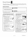
Recognize Safety Symbols, Words, and Labels
_IL
DANGER--Immediate
_IL
WARNING--Hazards
_k,
DANGER
hazards which WILL result in severe personal injury or death.
WARNING
or unsafe practices which COULD result in severe personal injury or death.
CAUTION
CAUTION--Hazards or unsafe practices which COULD result in minor personal injury or product or property
damage.
RS1300005
Rev. 0
2
Table of Contents
Important Information ................................................
Product Design ..........................................................
Component Testing ....................................................
Service Procedures .................................................
2
4
5
10
Service Equipment ..................................................
Drier Replacement ...................................................
Refrigerant Precautions ...........................................
Line Piercing Valves .................................................
Open Lines .............................................................
Compressor Operational Test ...................................
Dehydrating Sealed Refrigeration System ..................
Leak Testing ............................................................
Testing Systems Containing a
Refrigerant Charge ............................................
Testing Systems Containing
No Refrigerant Charge .......................................
Restrictions .............................................................
10
10
11
1t
11
11
12
12
Symptoms .........................................................
Testing for Restrictions .......................................
Evacuation and Charging .........................................
Evacuation ........................................................
13
13
14
14
Charging ...........................................................
Refrigerant Charge ............................................
HFC134a Service Information ...................................
15
15
16
System Diagnosis ....................................................
Disassembly Procedures
Refrigerator Compartment ....................................
Upper Light Socket & Lens .................................
Freezer Cold Control ..........................................
Defrost Timer ..........................................................
12
13
Machine Compartment
Water Valves .....................................................
Condenser Fan motor and Blade ........................
Health, Safety, and Handling ...............................
16
Comparison of CFC12 and HFC134a Properties .. 16
Replacement Service Compressor ............................
17
Compressor Testing Procedures .........................
17
Brazinc ...................................................................
17
18
19
20
Ice and Water Dispenser Diagram ............................
Water Valves Diagram ..................................................
Typical External Sweat Pattern ..................................
Troubleshooting Chart ................................................
21
22
23
24
30
30
30
30
Adaptive Defrost Control ....................................
Damper Control .......................................................
Water Filter Assembly .............................................
Water Tank Assembly ..............................................
Crisper Cover and Socket ..................................
Freezer Compartment
Freezer Light Socket ..........................................
Auger Motor Assembly .......................................
Auger Motor ......................................................
Auger Motor Capacitor ............................................
Evaporator Fan Motor Assembly .........................
Evaporator Fan Motor and Fan Blade .....................
Evaporator Removal ...............................................
Defrost Terminator (Thermostat) .........................
Defrost Heater ...................................................
Ice Maker Removal .................................................
12
Refrigerant Flow 22, 24, 26 cu. ft ..............................
Cabinet Air Flow 24, 26 cu. ft ....................................
Cabinet Air Flow 22 cu. ft ..........................................
27
Compressor ......................................................
Condensate Drain Tube .....................................
Condensate Drain Pan .......................................
3
30
31
31
31
31
31
31
31
32
32
32
32
32
32
33
33
33
33
33
33
Overload/Relay ..................................................
Condenser ........................................................
Bottom of Cabinet
34
34
Front Leveling Rollers ........................................
Rear Leveling Rollers .........................................
Cabinet Doors
Door Gaskets ....................................................
34
34
Dispenser Facade (Messenger Model) ................
Dispenser Ice Chute Door ..................................
Dispenser Light Socket ......................................
Dispenser D/C Solenoid .....................................
Dispenser Water Tube .......................................
High Voltage Board (Messenger Model) ..............
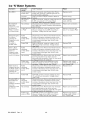
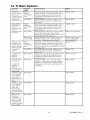
Ice 'N Water Systems
Troubleshooting of 5 button Dispenser ................
Troubleshooting of Messenger Dispenser ............
Troubleshooting of 3 button Dispenser ................
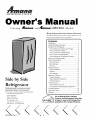
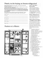
Appendix A
Owner's Manual ..................................................
34
35
35
35
35
35
RS1300005
34
36
40
45
A-2
Rev. 0
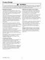
Product Design
WARNING
To avoid risk of electrical shock, personal injury, or death, disconnect electrical power source to unit, unless test
procedures require power to be connected. Discharge capacitor through a resistor before attempting to service.
Ensure all ground wires are connected before certifying unit as repaired and/or operational.
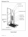
Refrigeration
System
Defrost
Compressor forces high temperature vapor into fan
cooled tube and wire condenser where vapor is cooled
and condensed into high pressure liquid by circulation
of air across condenser coil. (See Refrigerant Flow
Diagram, page 18)
Defrost heater is suspended on left side of evaporator
coil and across bottom to keep defrost drain free
flowing during defrost. Defrost water is caught in
trough under evaporator coil and flows through drain
hole in liner and drain tubing into drain pan. Air
circulated by condenser fan over pan evaporates
water.
Capillary enters evaporator at top back. Combined
liquid and saturated gas flows through back to bottom
of coil and into suction line. Aluminium tube evaporator
coil is located in freezer compartment where
circulating evaporator fan moves air through coil and
into fresh food compartment.
Adaptive
Large surface of evaporator allows heat to be
absorbed from both fresh food and freezer
Saturated gas is drawn off through suction line where
superheated gas enters compressor. To raise
temperature of gas, suction line is placed in heat
exchange with capillary.
Controls
Freezer compartment temperature is regulated by air
sensing thermostat at rear back of fresh food
compartment which actuates compressor. Control
capillary is inserted in well which routes capillary into
freezer. Control should be set to maintain freezer
between 0 ° to -2°F.
Fresh food compartment temperature is regulated an
air damper control governing amount of refrigerated
air entering fresh food compartment from freezer.
Fresh food compartment temperature should be
between 38 ° and 40°F.
RS1300005
Rev. 0
Defrost
System
(some models)
The ADC adapts the compressor run time between
defrosts to achieve optimum defrost intervals by
monitoring the cold control and length the defrost
heater is on.
compartments by airflow over evaporator coil causing
some of the liquid to evaporate. Temperature of
evaporator tubing near end of running cycle may vary
from -13 ° to -25°F.
temperature
(some models)
Defrost terminator (thermostat) is wired in series with
defrost heater. Terminator opens and breaks circuit
when preset high temperature is reached. After
defrost thermostat opens, thermostat remains open
until end of defrost cycle when cooling cycle starts and
terminator senses present low temperature and
closes.
High pressure liquid passes into post-condenser loop
which helps to prevent condensation around freezer
compartment opening and through molecular sieve
drier and into capillary tube. Small inside diameter of
capillary offers resistance, decreasing pressure, and
temperature of liquid discharged into evaporator.
Capillary diameter and length is carefully sized for
each system.
Temperature
Timer System
Every 8 hours of compressor run time defrost timer
activates radiant electric defrost heater suspended
from evaporator. After 33 minutes of defrost cycle
time, timer restores circuit to compressor.
4
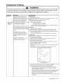
Component Testing
WARNING
I
To avoid risk of electrical shock, personal injury, or death, disconnect electrical power source to unit, unless test
procedures require power to be connected. Discharge capacitor through a resistor before attempting to service.
Ensure all ground wires are connected before certifying unit as repaired and/or operational.
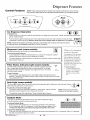
Component
Compressor
Description
When compressor electrical circuit is
energized, the start winding current
causes relay to heat. After an amount of
starting time, the start winding circuit
turns off. The relay will switch off the
start winding circuit even though
compressor has not started (for example,
when attempting to restart after
momentary power interruption).
Test Procedures
Resistance test
1. Disconnect power to unit.
2. Discharge capacitor by shorting across terminals with a resistor for 1 minute.
NOTE: (Some compressors do not have a run capacitor.)
3. Remove leads from compressor terminals.
4. Set ohmmeter to lowest scale.
5. Check for resistance between
Terminals "S" and "C", start winding
Terminals "R" and "C", run winding
If either compressor winding reads open (infinite or very high resistance) or
dead short (0 ohms), replace compressor.
With "open" relay, compressor will not
start because there is little or no current
Ground test
to start windings. Overload protection will
1. Disconnect power to refrigerator.
open due to high locked rotor run winding
2. Discharge capacitor, if present, by shorting terminals through a resistor.
current.
3. Remove compressor leads and use an ohmmeter set on highest scale.
4. Touch one lead to compressor body (clean point of contact) and other probe
With "shorted" relay or capacitor,
to each compressor terminal.
compressor will start and overload
• If reading is obtained, compressor is grounded and must be replaced.
_rotector will quickly open due to high
current of combined run and start
Operation test
If voltage, capacitor, overload, and motor winding tests do not show cause for
windings.
failure, perform the following test:
1. Disconnect power to refrigerator.
With open or weak capacitor,
2. Discharge capacitor by shorting capacitor terminals through a resistor.
compressor will start and run as normal
3. Remove leads from compressor terminals.
but will consume more energy.
4. Wire a test cord to power switch.
5. Place time delayed fuse with UL rating equal to amp rating of motor in test
cord socket. (Refer to Technical Data Sheet)
6. Remove overload and relay.
7. Connect start, common and run leads of test cord on appropriate terminals of
compressor.
8. Attach capacitor leads of test cord together. If capacitor is used, attach
capacitor lead to a known good capacitor of same capacity.
To AC supply
_Capacitor
Test configuration
9. Plug test cord into multimeter to determine start and run wattage and to check
for low voltage, which can also be a source of trouble indications.
10. With power to multimeter, press start cord switch and release.
• If compressor motor starts and draws normal wattage, compressor is
okay and trouble is in capacitor, relay/overload, freezer temperature
control, or elsewhere in system.
• If compressor does not start when direct wired, recover refrigerant at high
side. After refrigerant is recovered, repeat compressor direct wire test. If
compressor runs after recovery but would not run when direct wired
before recover, a restriction in sealed system is indicated.
• If compressor does not run when wired direct after recovery, replace faulty
compressor.
5
RS1300005
Rev. 0
Component Testing
I
WARNING
I
To avoid risk of electrical shock, personal injury, or death, disconnect electrical power source to unit, unless test
procedures require power to be connected. Discharge capacitor through a resistor before attempting to service.
Ensure all ground wires are connected before certifying unit as repaired and/or operational.
Component
Capacitor
Description
Run capacitor connects to relay
terminal 3 and L side of line.
Test Procedures
WARNING
Some compressors do not require a run
capacitor; refer to the Technical Data
Sheet for the unit being serviced.
To avoid electrical shock which can cause severe personal injury or death,
discharge capacitor through a resistor before handling.
1. Disconnect power to refrigerator.
2. Remove capacitor cover and disconnect capacitor wires.
3. Discharge capacitor by shorting across terminals with a resistor for 1 minute.
4. Check resistance across capacitor terminals with ohmmeter set on "X1 K"
scale.
•
•
•
•
Condenser
Condenser is a tube and wire
construction located in machine
compartment.
Condenser is on high pressure discharge
side of compressor. Condenser function
is to transfer heat absorbed by refrigerant
to ambient.
Higher pressure gas is routed to
condenser where, as gas temperature is
reduced, gas condenses into a high
pressure liquid state. Heat transfer takes
_lace because discharged gas is at a
higher temperature than air that is
passing over condenser. It is very
important that adequate air flow over
condenser is maintained.
Condenser is air cooled by condenser
fan motor. If efficiency of heat transfer
from condenser to surrounding air is
impaired, condensing temperature
becomes higher. High liquid temperature
means liquid will not remove as much
heat during boiling in evaporator as
under normal conditions. This would be
Good--needle
swings to 0 ohms and slowly moves back to infinity.
Open--needle does not move. Replace capacitor.
Shorted--needle
moves to zero and stays. Replace capacitor.
High resistance leak--needle jumps toward 0 and then moves back to
constant high resistance (not infinity).
Leaks in condenser can usually be detected by using an electronic leak detector
or soap solution. Look for signs of compressor oil when checking for leaks. A
certain amount of compressor oil is circulated with refrigerant.
Leaks in post condenser
For minute leaks
1. Separate condenser from rest of refrigeration system and pressurize
condenser up to a maximum of 235 PSI with a refrigerant and dry nitrogen
combination.
2. Recheck for leaks.
WARNING
To avoid severe personal injury or death from sudden eruption of high
pressures gases, observe the following:
Protect against a sudden eruption if high pressures are required for leak
checking.
Do not use high pressure compressed gases in refrigeration systems
without a reliable pressure regulator and pressure relief valve in the
lines.
indicated by high than normal head
_ressures, long run time, and high
wattage. Remove any lint or other
accumulation, that would restrict normal
air movement through condenser.
From condenser the refrigerant flows into
a post condenser loop which helps
control exterior condensation on flange,
center mullion, and around freezer door.
Refrigerant the flows through the drier to
_vaporator and into compressor through
suction line.
RS1300005
Rev. 0
loop are rare because loop is a one-piece copper tube.
6
Component Testing
WARNING
I
To avoid risk of electrical shock, personal injury, or death, disconnect electrical power source to unit, unless test
procedures require power to be connected. Discharge capacitor through a resistor before attempting to service.
Ensure all ground wires are connected before certifying unit as repaired and/or operational.
Component
Overload / Relay
Description
When voltage is connected and relay is
cool, current passes through relay to start
winding.
After a short time, current heats the
resistor in relay and resistance will rise
blocking current flow through relay.
Test Procedures
1. Disconnect power to the refrigerator.
2. Remove relay cover and disconnect leads.
3. Check resistance across terminals 2 and 3 with an ohmmeter:
Normal = 3 to 12 ohms
Shorted = 0 ohms
Open = infinite ohms
Start winding remains in the circuit through
run capacitor.
Freezer
temperature
control
Solid state relay plugs directly on
compressor start and run terminals. Relay
terminals 2 and 3 are connected within
relay. Run capacitor is connected to relay
terminal 3. L2 side of 120 VAC power is
connected to relay terminal 2.
Freezer temperature control is a capillary
tube operating a single pole, single throw
switch.
Freezer temperature control controls run
cycle through defrost timer.
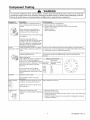
Altitude Adjustment
When altitude adjustment is required on a
G.E. control, turn altitude adjustment
screw 1/7 turn counter clockwise for each
Check for proper calibration with thermocouple capillary in air supply well by
recording cutqn and cut-out temperatures at middle setting. Refer to tech sheet
for model being serviced for expected temperatures.
Check control contacts are opening by disconnecting electrical leads to control
and turning control knob to coldest setting. Check for continuity across
terminals.
Altitude Counter in Feet
Turn Screw
Feet Above
1,000 feet increase in altitude up to 10,000 Sea Level
feet. One full turn equals 10,000 feet
maximum.
2,000
4,000
In most cases the need for altitude
6,000
adjustments can be avoided by simply
8,000
turning temperature control knob to colder
10,000
setting.
Ice Maker
3O
81
129
174
216
Optional on some models.
See "Ice Maker" section
information.
ECM condenser
motor
Clockwise (Angular
Degrees)
for service
Condenser fan moves cooling air across
condenser coil and compressor body.
Check resistance
across coil.
Condenser fan motor is in parallel circuit
with compressor.
Evaporator fan
motor
Evaporator fan moves air across
evaporator coil and throughout refrigerator
cabinet.
1. Disconnect
2. Disconnect
power to unit.
fan motor leads.
3. Check resistance from ground connection solder. Trace to motor frame must
not exceed .05 ohms.
4. Check for voltage at connector to motor with unit in refrigeration mode and
compressor operating.
7
RS1300005
Rev. 0
Component Testing
I
I
WARNING
To avoid risk of electrical shock, personal injury, or death, disconnect electrical power source to unit, unless test
procedures require power to be connected. Discharge capacitor through a resistor before attempting to service.
Ensure all ground wires are connected before certifying unit as repaired and/or operational.
Component
Refrigerator
switch
light
Description
Single pole, single throw switch
completes circuit for light when door is
open.
Test Procedures
Check resistant across terminals.
Switch arm depressed
"NO" terminals
Open
Switch arm up
"NO" terminals
Closed
Freezer light /
Interlock switch
Single pole, Double throw switch
completes circuit for light when door is
open. Completes circuit for dispenser
when door is closed
Check resistant across terminals.
Drier
Drier is placed at post condenser loop
outlet and passes liquefied refrigerant to
capillary.
Drier must be changed every time the system is opened for testing or
compressor replacement.
NOTE: Drier used in R12 sealed system is not interchangeable with
drier used in R134a sealed system. Always replace drier in R134a
system with Amana part number B2150504.
Desiccant
Grams
(20) 8 x 12 4AXH - 7 M>S> -
Switch arm depressed
"NO" terminals
Open
"NC" terminals
Closed
Switch arm not depressed
"NC" terminals
Open
"NO" terminals
Closed
Before opening refrigeration
disposal.
1.
2.
3.
4.
5.
6.
system, recover HFC134a refrigerant
for safe
Cut drier out of system using the following procedure. Do not unbraze drier.
Applying heat to remove drier will drive moisture into the system.
Score capillary tube close to drier and break.
Reform inlet tube to drier allowing enough space for large tube cutter.
Cut circumference of drier 1 W' below condenser inlet tube joint to drier.
Remove drier.
7. Apply heat trap paste on post condenser tubes to protect grommets from higt
heat.
8. Unbraze remaining part of drier. Remove drier from system.
9. Discard drier in safe place. Do not leave drier with customer.
under warranty, old drier must accompany warranty claim.
1
If refrigerator
WARNING
is
J
To avoid death or severe personal injury, cut drier at correct location.
Cutting drier at incorrect location will allow desiccant beads to scatter. If
spilled, completely clean area of beads.
Defrost timer
Z
Adaptive defrost
control (ADC)
Timer motor operates only when freezer
control is closed.
After specified amount of actual
operating time, inner cam in timer throws
the contacts from terminal 4, compressor
circuit, to terminal 2, defrost
thermostat/defrost
heater circuit.
After specified defrost cycle time, timer
cam resets the circuitry through terminal
4 to compressor.
The ADC adapts the compressor run
time between defrosts to achieve
1. To check timer motor winding, check for continuity between terminals
of timer.
2. Depending on rotating position of the cam, terminal 1 of timer is common to
both terminal 2, the defrost mode, and terminal 4, the compressor mode.
There should never be continuity between terminals 2 and 4.
3. With continuity between terminals 1 and 4, rotate timer knob clockwise until
audible click is heard. When the click is heard, reading between terminals 1
and 4 should be infinite and there should be continuity between terminals 1
and 2.
4. Continuing to rotate time knob until a second click is heard should restore
circuit between terminals 1 and 4.
Refer to specific Technical
optimum defrost intervals by monitoring
the cold control and length the defrost
heater is on.
RS1300005
Rev. 0
1 and
8
Data Sheet with unit for troubleshooting
procedure.
Component Testing
I
WARNING
To avoid risk of electrical shock, personal injury, or death, disconnect electrical power source to unit, unless test
procedures require power to be connected. Discharge capacitor through a resistor before attempting to service.
Ensure all ground wires are connected before certifying unit as repaired and/or operational.
Water valve
Description
Controls water flow to the ice maker.
Controlled by thermostat
Test Procedures
Check resistance
across coil windings.
in ice maker.
See Ice Maker Section for further
information.
Evaporator
Inner volume of evaporator allows liquid
refrigerant discharged from capillary to
9xpand into refrigerant gas.
Test for leaks in evaporator with electronic leak detector or with soap solution.
Compressor oil is circulated with refrigerant; check for oil when checking for
leaks.
Expansion cools evaporator tube and fin
temperature to approximately -20°F
transferring heat from freezer section to
refrigerant.
For minute leaks
Passing through suction line to
compressor, the refrigerant picks up
superheat (a relationship between
pressure and temperature that assures
complete vaporization of liquid
refrigerant) as the result of capillary tube
soldered to suction line.
Refrigerant gas is pulled through suction
line by compressor, completing
refrigeration cycle.
Evaporator defrost
heater
Thermostat
&ctivated when defrost thermostat,
defrost timer, and freezer control
complete circuit through heater.
Thermostat is in a series circuit with
terminal 2 of defrost timer, and defrost
heater. Circuit is complete if evaporator
ran motor operates when cold.
1. Separate evaporator from rest of refrigeration system and pressurize
evaporator up to a maximum of 140 PSI with a refrigerant and dry nitrogen
combination.
2. Recheck for leaks.
WARNING
To avoid severe personal injury or death from sudden erruption of
high pressurres gases, observe the following:
•
•
Protect against a sudden eruption if high pressures are required
for leak checking.
Do not use high pressure compressed gases in refrigeration
systems without a reliable pressure regulator and pressure relief
valve in the lines.
Check resistance
across heater.
To check defrost system :
1. Thermocouple defrost thermostat and plug refrigerator into wattmeter.
2. Turn into defrost mode. Wattmeter should read specified watts (according to
Technical Data Sheet).
3. When defrost thermostat reaches specified temperature +5°F (see Technical
Data Sheet), thermostat should interrupt power to heater.
Test continuity across terminals.
With power off and evaporator coil below freezing, thermostat should show
continuity when checked with ohmmeter. See "Heater, evaporator (defrost)"
section for additional tests.
Controls the circuit from freezer
thermostat through defrost terminator to
defrost heater. Opens and breaks circuit
when thermostat senses preset high
temperature.
Damper Control
Damper control balances the air delivery
between refrigerator and freezer
compartments providing temperature
control for refrigerator.
After defrost thermostat opens, thermostat remains open until end of defrost
cycle and refrigerator starts cooling again. Defrost thermostat senses a preset
low temperature and resets (closes).
Subject capillary to appropriate temperature
model being serviced).
(refer to Technical
Damper door should close to within _A" of completely
Data Sheet for
shut.
Internal capillary activates damper
If altitude adjustment is required, turn altitude adjustment screw 1/8 turn
control and door closes restricting flow of clockwise for each 1,000 feet increase in altitude.
air from freezer compartment to
refrigerator compartment.
There are no electrical connections to damper control. See Technical Data Sheet
for damper specifications for unit being serviced.
9
RS1300005
Rev. 0
Service Procedures
WARNING
To avoid risk of electrical shock, personal injury, or death, disconnect electrical power source to unit, unless test
procedures require power to be connected. Discharge capacitor through a 10,000 ohm resistor before attempting
to service. Ensure all ground wires are connected before certifying unit as repaired and/or operational.
Service
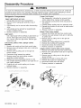
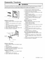
Drier Replacement
Equipment
Listed below is equipment needed for proper servicing
of HFC134a systems. Verify equipment is confirmed
by manufacturer as being compatible with HFC134a
and ester oil system.
Before opening refrigeration system, recover
HFC134a refrigerant for safe disposal.
Every time sealed HFC134a system is repaired, drier
filter must be replaced with, part # B2150504.
Equipment must be exclusively used for HFC134a.
Exclusive use of equipment only applies to italic items.
Cut drier out of system by completing the following
steps. Do not unbraze drier filter. Applying heat to
remove drier will drive moisture into system.
• Evacuation pump
Check with vacuum pump supplier to verify equipment
is compatible for HFC134a. Robinair, Model 15600
2 stage, 6 cubic feet per minute pump is
recommended.
• Four-way manifold gauge set, with low loss hoses
• Leak detector
WARNING
To avoid risk of severe personal injury or death, cut
drier at correct location. Cutting drier at incorrect
location will allow desiccant beads to scatter.
Completely clean area of beads, if spilled.
• Charging cylinder
• Line piercing saddle valve
(Schroeder valves). Seals must be HFC134a and
ester oil compatible. Line piercing valves may be used
for diagnosis but are not suitable for evacuation or
charging, due to minute holes pierced in tubing. Do
not leave mechanical access valves on system.
Valves eventually will leak. Molecules of HFC134a are
smaller than other refrigerants and will leak where
other refrigerants would not.
Swagging tools
Flaring tools
Tubing cutter
Flux
SiI-Fos
Silver solder
Oil for swagging and flaring
Use only part # R0157532
• Copper tubing
Use only part # R0174075 and # R0174076
• Dry nitrogen
99.5% minimum purity, with -40°F or lower dew point
• Crimp tool
• Tube bender
•
•
•
•
Micron vacuum gauge
Process tube adaptor k#
Heat trap paste
ICI appliance grade HFCI34a
RS1300005
Rev. 0
10
1.
Score capillary tube close to drier and break.
2.
Reform inlet tube to drier allowing enough space
for large tube cutter.
3.
Cut circumference of drier at 1-1/4", below
condenser inlet tube joint to drier.
4.
Remove drier.
5.
Apply heat trap paste on post condenser tubes to
protect grommets from high heat.
6.
Unbraze remaining part of drier. Remove drier
from system.
7.
Discard drier in safe place. Do not leave drier with
customer. If refrigerator is under warranty, old
drier must accompany warranty claim.
Service Procedures
WARNING
To avoid risk of electrical shock, personal injury, or death, disconnect electrical power source to unit, unless test
procedures require power to be connected. Discharge capacitor through a 10,000 ohm resistor before attempting
to service. Ensure all ground wires are connected before certifying unit as repaired and/or operational.
Refrigerant
Precautions
To AC supply
WARNING
]
Switch
To avoid risk of personal injury, do not allow
refrigerant to contact eyes or skin.
Compressor
Fuses
CAUTION
]
To avoid risk of property damage, do not use
refrigerant other than that shown on unit serial
number identification plate.
NOTE: All precautionary measures recommended by
refrigerant manufacturers and suppliers apply
and should be observed.
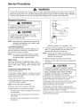
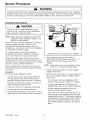
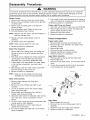
Line Piercing
Attaching Capacitor for Compressor Test
Valves
5. Connect a known good capacitor into circuit as shown
above. For proper capacitor size and rating, see
technical data sheet for unit under test.
Line piercing valves can be used for diagnosis, but
are not suitable for evacuating or charging due to
holes pierced in tubing by valves.
NOTE: Ensure test cord cables and fuses meet
NOTE: Do not leave line piercing valves on system.
Connection between valve and tubing is not
hermetically sealed. Leaks will occur.
specifications for unit under test (see Technical
Sheet for unit under test).
6. Replace compressor protector cover securely.
Open Lines
7. Plug test cord into outlet, then press and release start
cord switch.
During any processing of refrigeration system, never
leave lines open to atmosphere. Open lines allow water
vapor to enter system, making proper evacuation more
difficult.
Compressor
Operational
i
If compressor voltage, capacitor, overload, and motor
winding tests are successful (do not indicate a fault),
perform the following test:
If compressor runs when direct wired, it is working
properly. Malfunction is elsewhere in system.
power to unit.
2.Discharge capacitor by shorting capacitor
terminals through a resistor.
If compressor does not start when direct wired, recover
system at high side. After the system is recovered,
repeat compressor direct wire test.
NOTE: Not all units have run capacitor.
3.Remove leads from compressor
]
To avoid risk of damage to compressor windings,
immediately disconnect (unplug) test cord from power
source if compressor does not start. Damage to
compressor windings occurs if windings remain
energized when compressor is not running.
Test
(short term testing only)
1.Disconnect
CAUTION
terminals.
If compressor runs after system is recovered (but
would not operate when wired direct before recovery) a
restriction in sealed system is indicated.
4.Attach test cord to compressor windings.
• Common lead on test cord attaches to C terminal
If motor does not run when wired direct after recovery,
replace faulty compressor.
on compressor.
• Start lead on test cord attaches to S terminal on
compressor.
• Run lead on test cord attaches to M terminal on
compressor.
11
RS1300005
Rev. 0
Service Procedures
WARNING
To avoid risk of electrical shock, personal injury, or death, disconnect electrical power source to unit, unless test
procedures require power to be connected. Discharge capacitor through a 10,000 ohm resistor before attempting
to service. Ensure all ground wires are connected before certifying unit as repaired and/or operational.
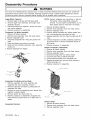
Dehydrating
Sealed Refrigeration
Testing Systems Containing No Refrigerant Charge
1. Connect cylinder of nitrogen, through gauge
manifold, to process tube of compressor and liquid
line strainer.
System
Moisture in a refrigerator sealed system exposed to
heat generated by the compressor and motor reacts
chemically with refrigerant and oil in the system and
forms corrosive hydrochloric and hydrofluoric acids.
These acids contribute to breakdown of motor winding
insulation and corrosion of compressor working parts,
causing compressor failure.
2. Open valves on nitrogen cylinder and gauge manifold.
Allow pressure to build within sealed system.
3. Check for leaks using soap suds.
If a leak is detected in a joint, do not to attempt to repair
by applying additional brazing material. Joint must be
disassembled, cleaned and rebrazed. Capture refrigerant
charge (if system is charged), unbraze joint, clean all
parts, then rebraze.
In addition, sludge, a residue of the chemical reaction,
coats all surfaces of sealed system, and will eventually
restrict refrigerant flow through capillary tube.
To dehydrate sealed system, evacuate system (see
paragraph Evacuation).
If leak is detected in tubing, replace tubing. If leak is
detected in either coil, replace faulty coil.
Leak Testing
[
DANGER
1
To avoid risk of serious injury or death from violent
explosions, NEVER use oxygen or acetylene for
pressure testing or clean out of refrigeration
systems. Free oxygen will explode on contact with
oil. Acetylene will explode spontaneously when put
under pressure.
It is important to check sealed system for refrigerant
leaks. Undetected leaks can lead to repeated service
calls and eventually result in system contamination,
restrictions, and premature compressor failure.
Refrigerant leaks are best detected with halide or
electronic leak detectors.
Testing Systems Containing a Refrigerant Charge
1. Stop unit operation (turn refrigerator off).
2. Holding leak detector exploring tube as close to
system tubing as possible, check all piping, joints,
and fittings.
NOTE: Use soap suds on areas leak detector cannot
reach or reliably test.
RS1300005
Rev. 0
12
Service Procedures
WARNING
To avoid risk of electrical shock, personal injury, or death, disconnect electrical power source to unit, unless test
procedures require power to be connected. Discharge capacitor through a 10,000 ohm resistor before attempting
to service. Ensure all ground wires are connected before certifying unit as repaired and/or operational.
Restrictions
3. Visually check system for kinks in refrigeration line
which is causing restriction. Correct kink and repeat
step 2.
Symptoms
Restrictions in sealed system most often occur at
capillary tube or filter drier, but can exist anywhere on
liquid side of system.
Restrictions reduce refrigerant flow rate and heat
removal rate. Wattage drops because compressor
not circulating normal amount of refrigerants.
4. Turn unit off and time how long it takes high and low
pressure gauges to equalize:
• If pressure equalization takes longer than 10
minutes, a restriction exists in the capillary tube or
drier filter. Go to step 5.
is
Common causes of total restrictions are moisture,
poorly soldered joints, or solid contaminants. Moisture
freezes at evaporator inlet end of capillary tube. Solid
contaminants collect in filter drier.
• If pressure equalization takes less than 10 minutes,
system is not restricted. Check for other possible
causes of malfunction.
5. Recover refrigerant in sealed system.
If restriction is on low side, suction pressure will be in a
vacuum and head pressure will be near normal.
NOTE: Before opening any refrigeration system,
capture refrigerant in system for safe disposal.
If restriction is on high side, suction pressure will be in
a vacuum and head pressure will be higher than
normal during pump out cycle.
6. Remove power from unit.
Refrigeration occurs on low pressure side of partial
restriction. There will be a temperature difference at
the point of restriction. Frost and/or condensation will
be present in most case at the point of restriction.
Also, system requires longer to equalize.
CAUTION
To avoid risk of personal injury or property damage,
take necessary precautions against high
temperatures required for brazing.
Slight or partial restriction can give the same
symptoms as refrigerant shortage including lower than
normal back pressure, head pressure, wattage, and
warmer temperatures.
7. Remove and replace restricted device.
8. Evacuate sealed system.
9. Charge system to specification.
Total restriction on the discharge side of compressor,
when restriction is between compressor and first half
of condenser, results in higher than normal head
pressure and wattage while low side is being pumped
out.
NOTE: Do not use captured or recycled refrigerant in
Amana units. Captured or recycled refrigerant
voids any Amana and/or compressor
manufacturer's warranty.
NOTE: Charge system with exact amount of refrigerant.
Refer to unit nameplate for correct refrigerant
charge. Inaccurately charged system will cause
future problems.
Testing for Restrictions
To determine if a restriction exists:
1. Attach gauge and manifold between suction and
discharge sides of sealed system.
2. Turn unit on and allow pressure on each side to
stabilize. Inspect condenser side of system. Tubing
on condenser should be warm and temperature
should be equal throughout (no sudden drops at any
point along tubing).
• If temperature of condenser tubing is consistent
throughout, go to step 4.
• If temperature of condenser tubing drops suddenly
at any point, tubing is restricted at point of
temperature drop (if restriction is severe, frost may
form at point of restriction and extend down in
direction of refrigerant flow in system). Go to step 5.
13
RS1300005
Rev. 0
Service Procedures
WARNING
To avoid risk of electrical shock, personal injury, or death, disconnect electrical power source to unit, unless test
procedures require power to be connected. Discharge capacitor through a 10,000 ohm resistor before attempting
to service. Ensure all ground wires are connected before certifying unit as repaired and/or operational.
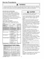
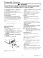
Evacuation
and Charging
1
CAUTION
Thermistor
Vacuum Gauge
]
Low Side
auge
E
Side Gauge
i
To avoid risk of fire, sealed refrigeration system
must be air free. To avoid risk of air contamination,
follow evacuation procedures exactly.
D
Drier/Process
Tube
Hose
Compressor
NOTE:
Before opening any refrigeration system, EPA
regulations require refrigerant in system to be
captured for safe disposal.
Proper evacuation of sealed refrigeration system is an
important service procedure. Usable life and
operational efficiency greatly depends upon how
completely air, moisture and other non-condensables
are evacuated from sealed system.
_Tube
.6 cm
Tubing
Vacuum Pump
Charging
Cylinder
Air in sealed system causes high condensing
temperature and pressure, resulting in increased
power requirements and reduced performance.
Equipment Setup For Evacuation And Charging
5. After compound gauge (low side) drops to
approximately 29 inches gauge, open valve "C" to
vacuum thermocouple gauge and take micron
reading.
Moisture in sealed system chemically reacts with
refrigerant and oil to form corrosive hydrofluoric and
hydrochloric acids. These acids attack motor windings
and parts, causing premature breakdown.
NOTE: A high vacuum pump can only produce a good
vacuum if oil in pump is not contaminated.
Before opening system, evaporator coil must be at
ambient temperature to minimize moisture infiltration
into system.
,
Evacuation
7. At 600 microns, close valve "A" to vacuum pump and
allow micron reading in system to balance. Micron
level will rise.
To evacuate sealed refrigeration system:
1. Connect vacuum pump, vacuum tight manifold set
with high vacuum hoses, thermocouple vacuum
gauge and charging cylinder as shown in illustration.
• If in 2 minutes, micron level stabilizes at 1000
microns or below, system is ready to be charged.
Evacuation should be done through I.D. opening of
tubes not through line piercing valve.
• If micron level rises above 1000 microns and
stabilizes, open valve "A" and continue evacuating.
2. Connect low side line to compressor process tube.
• If micron reading rises rapidly and does not
stabilize, a leak still exists in system.
3. Connect high side line to drier/process tube.
4. Evacuate both simultaneously. With valve "C" and "F"
closed, open all other valves and start vacuum pump.
RS1300005
Rev. 0
Continue evacuating system until vacuum gauge
registers 600 microns.
Close valve "A" to vacuum pump and valve "C" to
vacuum gauge. Invert charging cylinder and open
charging cylinder valve "F" to add partial charge for
leak checking. With leak detector, check manifold
connections and system for leaks. After locating
leak, capture refrigerant, repair leak, and begin at
step 1.
14
Service Procedures
WARNING
To avoid risk of electrical shock, personal injury, or death, disconnect electrical power source to unit, unless test
procedures require power to be connected. Discharge capacitor through a 10,000 ohm resistor before attempting
to service. Ensure all ground wires are connected before certifying unit as repaired and/or operational.
Charging
NOTE: Do not use captured or recycled refrigerant in
Amana units. Captured or recycled refrigerant
voids any warranty.
Refrigerant
Charge
Refrigerant charge in all capillary tube systems is
critical and exact amount is required for proper
performance. Factory charges are shown on serial
plate.
NOTE: Do not use refrigerant other than shown on
serial plate.
NOTE: Charge system with exact amount of refrigerant.
Refer to unit serial plate for correct refrigerant
charge. Inaccurately charged system will cause
future problems.
To charge system:
1. Close valves "A" to vacuum pump and "C" to vacuum
gauge and "E" to low side manifold gauge.
2. Set scale on dial-a-charge cylinder for corresponding
HFC134a pressure reading.
3. Open valve "F" to charging cylinder and let exact
amount of refrigerant flow from cylinder into system.
Close valve.
Low side gauge pressure should rise shortly after
opening charging cylinder valve as system pressure
equalizes through capillary tube.
If pressure does not equalize, a restriction typically
exists at capillary/drier braze joint.
4. If pressure equalizes, open valve "E" to low side
manifold gauge and pinch off high side drier process
tube.
5. Start compressor and draw remaining refrigerant from
charging hoses and manifold into compressor
through compressor process tube.
6. To check high side pinch-off drier process tube. Close
valve "D" to high side gauge. If high side pressure
rises, repeat high side pinch-off and open valve "D".
Repeat until high side pinch-off does not leak.
7. Pinch-off compressor process tube and remove
charging hose. Braze stub closed while compressor is
operating.
8. Disconnect power. Remove charging hose and braze
high side drier process tube closed.
9. Recheck for refrigerant leaks.
15
RS1300005
Rev. 0
Service
Procedures
WARNING
To avoid risk of electrical shock, personal injury, or death, disconnect electrical power source to unit, unless test
procedures require power to be connected. Discharge capacitor through a 10,000 ohm resistor before attempting
to service. Ensure all ground wires are connected before certifying unit as repaired and/or operational.
HFC134a
Service
Information
CAUTION
HFC134a is alternative refrigerant for CFC12.
HFC134a has an ozone depletion potential (ODP)
factor of 0.0 and a global warming potential (GWP)
factor of 0.27. HFC134a is not flammable and has
acceptable toxicity levels. HFC134a is not
interchangeable with CFC12. There are significant
differences between HFC134a and CFC12 which must
be considered when handling and processing
refrigeration system.
To minimize contamination, exercise extreme care
when servicing HFC134A sealed systems.
• No trace of other refrigerants is allowed in HFC134a
systems. Chlorinated molecules in other refrigerants
such as CFC12, etc. will lead to capillary tube
plugging.
• Ester oil is used in HFC134a systems. Do not use
mineral oil. HFC134a and mineral oils cannot be
Health, Safety, and Handling
Health, safety and handling considerations for
HFC134A are virtually no different than those for
CFC12.
Health, Safety, and
Handlina
Allowable overall
exposure limit
Vaoor exposure to skin
Liauid exposure to skin
Vaoor
exoosure
to eve
Lieuid exoosure to eve
Above minimum exposure
limit
Safety and handling
CFC12
HFC134a
1,000 ppm
Same
No effect
Can cause frostbite
Very sliaht eve irritant
Can cause frostbite
Same
Same
Same
Same
Same
Can cause Asphyxiation,
Tachycardia, and Cardia
Arrhvthmias
Wear appropriate skin
and eye protection. Use
with adequate
ventilation.
Remove or extinguish
ignition or combustion
sources. Evacuate or
ventilate area
Same
Fire explosion hazards
May decompose if
contact with flames and
heating elements.
Container may explode
if heated due to resulting
pressure rise.
Combustion products
are toxic.
Recvcle or reclaim.
Same
procedures
• CFC12 has much higher tolerance to system
processing materials, such as drawing compounds,
rust inhibitors, and cleaning compounds, than
HFC134a. Such materials are not soluble in HFC134a
systems. If materials were to be washed from system
surfaces by ester oils, they could accumulate and
eventually plug capillary tube.
• Care must be taken to minimize moisture entering
HFC134a system. Do not leave compressor or system
open to atmosphere for more than 10 minutes.
Excessive moisture in HFC134a system will react with
compressor oil and generate acid.
• Compressor must be replaced when performing low
side leak repair.
• Drier filter must always be replaced with service drier
filter, part #B2150504.
Same
Spill management
Disoosal
mixed. If mineral oils were used in HFC134a systems,
lubricant would not return to compressor and would
cause early compressor failure. If significant amount of
oil has been lost from compressor, replace oil rather
than adding oil.
• Ester oils used in HFC134a systems are so
hydroscopic that by the time an inadequate system
performance is detected, oil will be saturated with
moisture.
Same
Important: Unbrazing drier filter from tubing will drive
moisture from desiccant and into system, causing
acids to form. Do not unbraze filter drier from tubing. If
CFC12 service drier was installed in HFC134A system,
drier could overload due to excessive moisture.
Com 3arison of CFC12 and HFC134a Properties
i=roDerties/Characteristics
Ozone Depletion Potential
(QPP)
GlobalWarming Potential
(GPW)
Molecular weight
Boiling point at 1 atmosphere
Vapor pressure at 77°F
CFC12
1.0"
HFCI34a
0.0"
3.2*
0.27*
121
102
-22°F (-30°C)
80 psig
-15°F (126°C)
82 psig
82 tb/ft _
No
75 tb/ft _
No
• HFC134a compatible copper tubing, part #R0174075
(1/4" O.D. X 18" length) and part #R0174076 (5/16"
O.D. X 24" length) must be used when replacing
tubing.
• Avoid system contamination by using Towerdraw E610
evaporating oil, part # R0157532, when flaring,
swagging, or cutting refrigeration tubing.
(25oc/
Liauid densitv at 77°F (25°C_
Flammability
High-side system operating
Pressure at 65°F (18°C)
Low-side system operating
Pressure at 65°F (18°C)
RS1300005
Rev. 0
HFC134a approximately 3 psig
higher than CFC12
HFC134a approximately 2 psig
lower than CFC12
16
Service
Procedures
WARNING
To avoid risk of electrical shock, personal injury, or death, disconnect electrical power source to unit, unless test
procedures require power to be connected. Discharge capacitor through a 10,000 ohm resistor before attempting
to service. Ensure all ground wires are connected before certifying unit as repaired and/or operational.
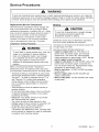
Replacement Service Compressor
Brazing
HFC134a service compressors will be charged with
ester oil and pressurized with dry nitrogen. Before
replacement compressor is installed, pull out 1 rubber
plug. A pop from pressure release should be heard. If
a pop sound is not heard, do not use compressor.
Positive pressure in compressor is vital to keep
moisture out of ester oil. Do not leave compressor
open to atmosphere for more than 10 minutes.
Compressor
Testing
1
CAUTION
]
To avoid risk of personal injury or property damage,
take necessary precautions against high
temperatures required for brazing.
Satisfactory results require cleanliness, experience,
and use of proper materials and equipment.
Procedures
Connections to be brazed must be properly sized, free
of rough edges, and clean.
WARNING
Generally accepted brazing materials are:
• Copper to copper joints: SIL-FOS (alloy of 15
percent silver, 80 percent copper, and 5 percent
phosphorous). Use without flux. Recommended
brazing temperature is approximately 1400°F. Do not
use for copper to steel connection.
• Copper to steel joints: SILVER SOLDER (alloy of 30
percent silver, 38 percent copper, 32 percent zinc).
Use with fluoride based flux. Recommended brazing
temperature is approximately 1200°F.
• Steel to steel joints: SILVER SOLDER (see copper
to steel joints).
• Brass to copper joints: SILVER SOLDER (see
copper to steel joints).
• Brass to steel joints: SILVER SOLDER (see copper
to steel joints).
To avoid death or severe personal injury, never use
oxygen, air or acetylene for pressure testing or
clean out of refrigeration system. Use of oxygen,
air, or acetylene may result in violent explosion.
Oxygen may explode on contact with oil and
acetylene will spontaneously explode when under
pressure.
Refer to Technical Data Sheet "Temperature
Relationship Chart" for operating watts, test points,
and temperature relationship test for unit being tested.
• Temperature testing is accomplished by using 3 lead
thermocouple temperature tester in specific locations.
Test point T-1 is outlet on evaporator coil and T-2 is
inlet. Test point T-3 is suction tube temperature
midway between where armaflex ends and suction
port of compressor (approximately 12 inches from
compressor).
• Thermocouple tips should be attached securely to
specified locations.
• Do not test during initial pull down. Allow one off cycle
or balanced temperature condition to occur before
proceeding with testing.
• Refrigerator must operate minimum of 20 minutes
after thermocouples are installed.
• Turn control to colder to obtain required on time.
• Wattage reading must be recorded in conjunction with
temperature test to confirm proper operation.
• Suction and head pressures are listed on
"Temperature and Relationship Chart". Normally these
are not required for diagnosis but used for confirmation
on systems which have been opened.
17
RS1300005
Rev. 0
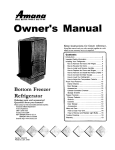
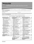
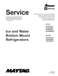
Refrigerant
Flow
SUCTION LINE
FLANGE
)R
IBE
INLET
HIGH
DRIER
CONDENSER
COMPRESSOR DISCHARGE
22, 24, 26 cu. ft. Side by Side
Refrigerant Flow Diagram
RS1300005
Rev. 0
18
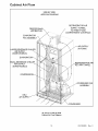
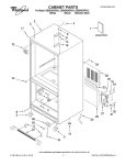
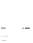
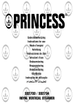
Cabinet
Air Flow
SIDE BY SIDE
AIRFLOW DIAGRAM
REFRI GERATOR AI R
SUPPLY TUNNEL
TO FRESH FOOD
COMPARTMENT CONTROLS
FREEZER BACK
(AIR BAFFLE)
EVAPORATOR
FAN ASSEMBLY
f
/
f
AIR SUPPLY
LARGE BEVERAGE
AIR SUPPLY
(SOME MODELS)
(IN FOAM)
CHILLER
BEVERAGE CHILLER
AIR SUPPLY
SOME MODELS)
CONDENSER FAN
ASSEMBLY
DELl
AI R SUPPLY
CONDENSER
24, 26 cu. ft. Side by Side
Cabinet Air Flow Diagram
19
RS1300005
Rev. 0
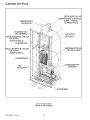
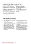
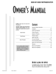
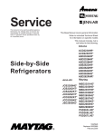
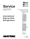
Cabinet
Air Flow
REFRIGERATOR AIR
COM PARTM ENT CONTROLS
SUPPLY TUNNEL
TO FRESH FOOD
FREEZER BACK
(AIR BAFFLE)
EVAPORATOR
FAN ASSEMBLY
LARGE BEVERAGE
AIR SUPPLY
CHILLER
(SOME MODELS)
EVAPORATOR
SMALL BEVERAGE
AIR SUPPLY
AIR SUPPLY
(IN FOAM)
_,
CHILLER
(SOME MODELS)
REFRIGERATOR AIF
RETURN TUNNEL
_!!
;R
i!!
_!!
i
i i!!
DELl
AIR SUPPLY
CONDENSER FAN
ASSEMBLY
_!!
i i!!
CONDENSER
22 cu. ft. Side by Side
Cabinet Air Flow Diagram
RS1300005
Rev, 0
20
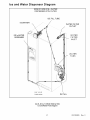
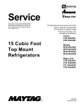
Ice and Water Dispenser
Diagram
SIDE BY SIDE ICE & WATER
DISPENSER WITH FILTER
ICE FILL TUBE
WATER
TANK
\*\
'\
5/16" X 5/16"
TUBE
UNION
22, 24, 26 cu. ft. Model Side by Side
Ice and Water Flow Diagram
21
RS1300005
Rev. 0
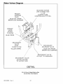
Vater Valves Diaaram
INCOMING
WATER
LINE CONNECTION
1/4" O.D
COPPER
TUBE
COMPRESSION
FITTING
PRIMARY
SOLENOID
VALVE
BLUE COIL WATER
BROWN COIL ICEMAKER
P RI MARY
VALVE
OUTLET
TO FILTER
BLUE STRIPE
SECONDARY
VALVE
INLET
FROM FILTER
YELLOW
SECONDARY
SOLENOID
VALVE
STRIPE
BLUE COIL WATER
BROWN COIL ICEMAKER
.,."
/
/
/
/
t
J
SECONDARY
VALVE
OUTLET
TO ICEMAKER
/'
/
/
/
SECONDARY
VALVE
OUTLET
WATER
TO WATER
TANK
DETAIL
22, 24, 26 cu. ft. Model Side by Side
Ice and Water Flow Diagram
RS1300005
Rev. 0
22
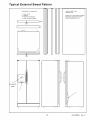
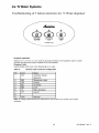
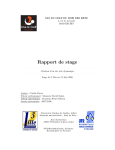
Typical
External
Sweat Pattern
Classification of condensation:
1
2
3
4
=
=
=
=
Conditions after 4 hour
laboratory test:
Haze or Fog
Beading
Beads or Small Drops
Drops Running Together
Ambient: 90°F, 84% relative humidity
Refrigerator compartment at 40°F
Freezer compartment at 0°F
i
IBTM
ILM
n
f--i
n
f
[-7
/o
3/
.t.._....
ICE CHUTE
DOOR
3
7
kJ
23
_
"
RS1300005
v
•
Rev. 0
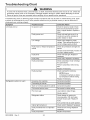
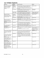
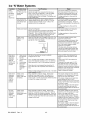
Troubleshooting
Chart
WARNING
To avoid risk of electrical shock, personal injury, or death, disconnect electrical power source to unit, unless test
procedures require power to be connected. Discharge capacitor through a resistor before attempting to service.
Ensure all ground wires are connected before certifying unit as repaired and/or operational.
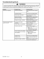
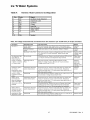
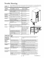
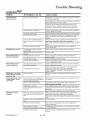
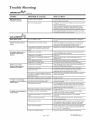
Troubleshooting chart on following pages contains symptoms that may be seen in malfunctioning units. Each
symptom is accompanied by one or more possible causes and by a possible remedy or test to determine if
components are working properly.
Symptom
Possible Causes
Corrective
Action
Unit does not run
No power to unit
Check for power at outlet. Check
fuse box/circuit breaker for blown
fuse or tripped breaker. Replace or
reset.
Faulty power cord
Check with test light at unit; if no
circuit and current is indicated at
outlet, replace or repair.
Low voltage
Check input voltage for proper
voltage. Take appropriate action to
correct voltage supply problem.
Faulty motor or freezer temperature
control
Check all connections are tight and
secure.
Jumper across terminals of control. If
unit runs, replace control.
Faulty timer
Check with test light. Replace if
necessary.
Faulty relay
Check relay. Replace if necessary.
Faulty compressor
Check compressor motor windings
for opens/shorts.
Perform compressor direct wiring
test.
Replace if necessary.
Faulty overload
Refrigerator section too warm
Check overload for continuity.
NOTE: Ensure
compressor/overload are below
trip temperature before testing.
Excessive door opening
Replace if necessary.
Consumer education
Overloading of shelves
Consumer education
Warm or hot foods placed in cabinet
Consumer education
Cold control set too warm
Set control to colder setting.
Poor door seal
Level cabinet. Adjust hinges.
Replace gasket.
Refrigerator airflow
Check damper is opening by
removing grille. With door open,
damper should open. Replace if
faulty.
Turn control knob to colder position.
RS1300005
Rev. 0
Interior light remains on
Check switch. Replace if necessary.
Faulty condenser fan or evaporator
fan
Check fan and wiring. Replace if
necessary.
Faulty compressor
Replace compressor.
24
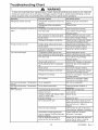
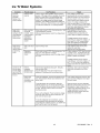
Troubleshooting
Chart
WARNING
To avoid risk of electrical shock, personal injury, or death, disconnect electrical power source to unit, unless test
procedures require power to be connected.
Discharge capacitor through a resistor before attempting to service.
Ensure all ground wires are connected before certifying unit as repaired and/or operational.
Possible
Symptom
Refrigerator
Freezer
warm
section
too cold
and refrigerator
sections
too
Causes
Corrective
Refrigerator
too cold
temperature
Refrigerator
adiusted
Temperature
airflow
control set
Adjust refrigerator
control.
set too warm
Poor door seal
Reset temperature
Dirty condenser
or obstructed
grille
Faulty control
Freezer
section
too cold
Freezer
Unit runs continuously
Check condenser
Test control.
shortage
or restriction
temp control set too cold
Adjust freezer
Cold control capillary not properly
clamped to evaporator
Temperature
control set too cold
Reposition
or obstructed
grille
Faulty condenser
fan
on
Check condenser
control.
and grille. Clean.
Faulty control
shortage
or restriction
Refrigerant
overcharge
Replace
if necessary.
Check fan and wiring.
necessary.
Test control.
Refrigerant
hinges.
gasket.
Check switch.
fan or evaporator
control.
if failed.
clamp and tighten.
Level cabinet. Adjust
light remains
if failed.
temperature
Replace
Adjust temperature
Replace
Unit runs continuously.
normal.
Unit runs continuously.
too cold.
Noisy operation
and grille. Clean.
Replace
Check for leak or restriction. Repair,
evacuate and recharge system.
Test control.
Dirty condenser
Poor door seal
hinges.
gasket.
Faulty control
Interior
controls.
Level cabinet. Adjust
Replace
Refrigerant
temperature
Check air flow.
not properly
controls
Action
Replace
Replace
if failed.
Check for leak or restriction. Repair,
evacuate and recharge system.
Check for overcharge.
recharge system.
Evacuate
Air in system
Check for low side leak. Repair,
evacuate and recharge system.
Temperature
Ice on evaporator
See "Ice on evaporator".
Temperature
Faulty defrost
thermostat
Loose flooring
or floor not firm
Check thermostat. Replace
necessary.
Repair floor or brace floor.
Cabinet
Tubing
tubing,
not level
if
and
if
Level cabinet.
in contact with cabinet,
or other metal
other
Drip pan vibrating
Adjust
tubing.
Adjust drain pan.
Fan hitting another
part
Ensure fan properly aligned and all
attaching hardware and brackets are
tight and not worn. Tighten or
replace.
Worn fan motor bearings
Check motor for loss of lubricant or
worn bearings. Replace if necessary.
Compressor mounting grommets
worn or missing. Mounting hardware
loose or missinq
Free or loose parts causing or
allowing noise during operation
Tighten hardware. Replace
grommets if necessary.
25
Inspect unit for parts that may have
worked free or loose or missing
screws. Repair as required.
RS1300005
Rev. 0
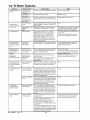
Troubleshooting
Chart
WARNING
To avoid risk of electrical shock, personal injury, or death, disconnect electrical power source to unit, unless test
procedures require power to be connected. Discharge capacitor through a resistor before attempting to service.
Ensure all ground wires are connected before certifying unit as repaired and/or operational.
Symptom
Possible Causes
Corrective Action
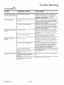
Frost or ice on evaporator
Defrost thermostat faulty
Check defrost thermostat. Replace if
failed.
Evaporator fan faulty
Check fan motor. Replace if failed.
Defrost heater remains open
Check defrost heater continuity.
Replace if failed.
Defrost control faulty
Check control and replace if failed.
Open wire or connector
Check wiring and connections.
Repair as necessary.
Refrigerant shortage or restriction
Check for leak or restriction. Repair,
evacuate and recharge system.
Loose wire or thermostat
connections
Check wiring and connections.
Repair as necessary.
Supply voltage out of specification
Check input voltage. Correct any
supply problems.
Overload protector open
Check overload protector for
continuity. If open, replace overload.
NOTE: Ensure
overload/compressor are below
trip temperature before testing.
Faulty compressor motor capacitor
Check capacitor for open/short.
Replace if necessary.
Unit starts and stops frequently
(cycles on and off)
(some compressors do not require
motor capacitor)
RS1300005
Rev. 0
NOTE: Discharge capacitor
before testing.
Faulty fan motor
Check fan motor. Replace if failed.
Restricted air flow
Check condenser and grille for dirt.
Clean.
Refrigerant shortage or restriction
Check for leak or restriction. Repair,
evacuate and recharge system.
26
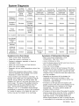
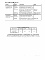
System Diagnosis
CONDITION
SUCTION
PRESSURE
VARIATION
FROM
NORMAL
HEAD
PRESSURE
VARIATION
FROM
NORMAL
T1 INLET
TEMPERATURE
VARIATION
FROM NORMAL
T2 OUTLET
TEMPERATURE
VARIATION
FROM NORMAL
T3 SUCTION
TEMPERATURE
VARIATION
FROM NORMAL
WATTAGE
VARIATION
FROM
NORMAL
Refrigerant
Overcharge
Increase
Increase
Warmer
Warmer
Colder
Increase
Shortage of
Refrigerant
Decrease
Decrease or
Increase
See Text
Colder
Warmer
Warmer
Decrease
Partial
Restriction
Decrease
Decrease or
Increase
See Text
Note 2
Colder
Warmer
Warmer
Decrease
Air in System
Near Normal
Increase
Warmer
Warmer
Warmer
Increase
Decrease
Decrease
Colder
Warmer
Warmer
Increase
Increase
Warmer
Warmer
Warmer
Increase
Normal or
Warmer or
Decrease
Colder
Warmer
Warmer
Decrease
Low Ambient
Installations
(High
Ambients the
Reverse)
Additional
Heat Load
Inefficient
Compressor
Symptoms
Increase
of an Overcharge
Symptoms
• Above normal freezer temperatures.
• Longer than normal or continuous run.
of Refrigeration
Decrease
Shortage
• Rise in food product temperature in both
compartments. (See Note 1 below.)
• Long or continuous run time.
• Look for obvious traces of oil that would occur due to a
• Freezing in refrigerator, especially on forced air
meatkeeper models.
• Higher than normal suction and head pressure.
• Higher than normal wattage.
• Evaporator inlet and outlet temperatures warmer than
normal.
• Suction tube temperature below ambient. Always
check for separated heat exchanger when suction
temperature is colder than ambient.
Various conditons could indicate an overcharge. For
example, if the cooling coil is not defrosted at regular
intervals, due to a failure of the defrost system, the
refrigerant will "flood out" and cause the suction line to
frost or sweat. The cause of this problem should be
corrected rather than to purge refrigerant from the
sytem. Running the freezer section colder than
necessary (-2 to -1 F. is considered normal package
temperatures) or continuous running of the compressor
for a variety of reasons, or the freezer fan motor not
running, may give the indication of an overcharge.
27
leak or cracked refrigerant line.
• Lower than normal wattage.
• Compressor will be hot to touch because of the heat
generated by the motor windings from long continuous
running. It will not be as hot as it would be with a full
charge and long run times for some other reason such
as a dirty condenser.
• Depending on the amount of the shortage, the
condenser will not be hot, but closer to room
temperature. The capillary tube will be warmer than
normal from a slight shortage.
• If the leak is on the high side of the system, both
gauges will show lower than normal readings and will
show progressively lower readings as this charge
becomes less. The suction pressure guage will
probably indicate a vacuum.
• If the leak is on the low side of the system the suction
pressure guage will be lower than normal - probably in
a vacuum - and the head pressure gauge will be
higher than normal. It will probably continue to
become higher because air drawn in through the leak
is compressed by the compressor and accumulates in
RS1300005
Rev. 0
System Diagnosis
the high side (condenser) of the system.
• Only partial frosting of evaporator instead of even
frosting of entire coil.
NOTE 1: Usually the first thing that is noticed by the
user is a rise in temperature foods. Although
temperatures will rise in both the freezer section
and the food compartment, the frozen meats
and vegetables will not thaw immediately. The
customer doesn't associate the problem with
the freezer section and will first notice that milk
and other food beverages are not cold enough.
Under some circumstances, such as in the case of
forced air meatkeeper model with a slight shortage of
refrigerant, freezing in the food compartment may be
experienced due to the additional running time. With a
refrigerant leak, however, it always gets worse and as
the refrigerant charge decreases the temperature will
continue to rise.
With a shortage of refrigerant the capillary line will not
have a full column of liquid. As a result, there is a
noticeable hissing sound in the evaporator. This should
not be mistaken for the regular refrigerant boiling
sounds that would be considered normal.
Symptoms
of a Restriction
Always remember refrigeration (cooling) occurs on the
low pressure side of a partial restriction (obviously a
total restriction will completely stop the circulation of
refrigerant and no cooling will take place).
Physically feel the refrigeration lines when a restriction
is suspected. The most common place for a restriction
is at the drier-filter or at the capillary tube inlet or outlet.
If the restriction is not total there will be a temperature
difference at the point of restriction, the area on the
evaporator side will be cooler. In many cases frost and/
or condensation will be present. A longer time is
required for the system to equalize.
Any kinked line will cause a restriction so the entire
system should be visually checked.
A slight restriction will give the same indications as a
refrigerant shortage with lower than normal back
pressure, head pressure, and wattage, warmer product
temperatures.
NOTE 2: If a total restriction is on the discharge side of
the compressor, higher than normal head
pressures and wattages would result. This is
true only while the low side is being pumped out
and if the restriction was between the
compressor and the first half of the condenser.
RS1300005
Rev. 0
28
To diagnose for a restriction versus a refrigerant
shortage, discharge the system, replace the drier-filter,
evacuate and recharge with the specified refrigerant
charge. If the unit performs normally three possibilities
exist: 1) refrigerant loss, 2) partially restricted drierfilter, and 3) moisture in system.
If the unit performs as it previously did you may have a
restricted capillary line or condenser or kinked line.
Find the point of restriction and correct it.
A restriction reduces the flow rate of the refrigerant and
consequently reduces the rate of heat removal.
Complete restriction may be caused by moisture, solid
contaminants in the system, or a poorly soldered joint.
Moisture freezes at the evaporator inlet end of the
capillary tube or solid contaminants collect in the drierfilter. The wattage drops because the compressor is not
circulating the usual amount of refrigerant.
As far as pressure readings are concerned, if the
restriction, such as a kinked line or a joint soldered shut
is anywhere on the low side, the suction pressure would
probably be in a vacuum while the head pressure will be
near normal. If the restriction is on the high side, the
suction pressure, again, will probably be in a vacuum
while the head pressure will be higher than normal
during the pump out period described earlier. In either
case, it will take longer than the normal ten minutes or
so for the head pressure to equalize with the low side
after the compressor stops.
Symptoms
of Air in System
This can result from a low side leak or improper
servicing. If a leak should occur on the low side, the
temperature control would not be satisfied; thus,
continuous running of the compressor would result. The
compressor would eventually pump the low side into a
vacuum drawing air and moisture into the system. Air
and R134A do not mix so the air pressure would be
added to the normal head pressure, resulting in higher
than normal head pressures.
One way to determine if air is in the system is to read
the head pressure gauge with the product off and
evaporator and condenser at the same temperature and
then take the temperature on the condenser outlet tube.
This temperature should be within 3 ° or 4° F. of what the
Pressure-Temperature Relation chart shows for the
given idle head pressure. If the temperature of the
condenser outlet is considerably lower than the idle
head pressure of the gauge this would indicate there is
air in the system.
Thorough leak checking is necessary. Correct the
source of the leak. Do not attempt to purge off the air
because this could result in the system being
undercharged. It is best to discharge, replace drier,
evacuate and recharge with the specified refrigerant
charge.
System Diagnosis
Symptoms of Low or High Ambient
Temperature
Installation
Lower ambient air temperature reduces the condensing
temperature and therefore reduces the temperature of
the liquid entering the evaporator. The increase in
refrigeration effect due to operation in a lower ambient
results in a decrease in power consumption and run
time. At lower ambients there is a reduction in cabinet
heat leak which is partially responsibile for lower power
consumption and run time.
An increase in refrigeration effect cannot be expected
below a certain minimum ambient temperature. This
temperature varies with the type and design of the
product.
Generally speaking, ambient temperatures cannot be
lower than 60 ° F. without affecting operating efficiency.
Conversely, the higher the ambient temperature the
higher the head pressure must be to raise the high side
refrigerant temperature above that of the condensing
medium. Therefore, head pressure will be higher as the
ambient temperature raises. Refrigerators installed in
ambient temperatures lower than 60 ° F. will not perform
as well because the pressures within the system are
generally reduced and unbalanced. This means that the
lower head pressure forces less liquid refrigerant
through the capillary line. The result is the symptoms of
a refrigerant shortage. The lower the ambient
temperature the more pronounced this condition
becomes.
When a point where the ambient temperature is below
the cut-in of the Temperature Control is reached, the
compressor won't run.
The drain traps will freeze in ambient temperatures
32 ° F.
of
Heat Load
A greater heat load can result from the addition of more
than normal supply of foods, such as after doing the
weekly shopping. Other items contributing to an
additional heat load would be excessive door openings,
poor door sealing, interior light remaining on, etc.
An increase in heat being absorbed by the refrigerant in
the evaporator will affect the temperature and pressure
of the gas returning to the compressor. Compartment
temperatures, power consumption, discharge, and
suction pressures are all affected by heat load.
Pressures will be higher than normal under heavy heat
load.
29
RS1300005
Rev. 0
Disassembly
Procedures
WARNING
To avoid risk of electrical shock, personal injury, or death, disconnect electrical power source to unit, unless test
procedures require power to be connected. Discharge capacitor through a resistor before attempting to service.
Ensure all ground wires are connected before certifying unit as repaired and/or operational.
Refrigerator
Freezer Cold Control
Compartment
1. See disassembly instructions for removal of cold
control, defrost timer, damper control assembly.
2. With assembly out disconnect wires and ground to
cold control.
Upper Light Sockets and Lens
1. Unsnap light cover from top of compartment.
2. Remove screws holding light assembly to top of
cabinet.
3. Carefully detach capillary tube from assembly holder.
4. Depress tab at bottom of cold contol to relase control
from assembly.
5. Reverse procedure to reassemble.
3. Light assembly can be removed after disconnecting
wires.
4. Light sockets can be removed by squeezing tabs
inward to release sockets.
Defrost Timer (some models)
1. Remove cold control and fresh food control knobs.
5. Reverse procedure to reassemble.
Light Switch
Use a taped putty knife to carefully pry light switch out
of liner. When light switch is free of compartment
liner, remove wires from light switch. Remove light
switch from unit.
2. Remove screw just between knobs and on right side
of control cover.
3. Remove cover by pulling cover to the right and
forward off tabs.
4. Release tabs holding defrost timer to assembly.
5. Remove timer by lifting off of assembly.
6. Disconnect harness from defrost timer.
7. Reverse procedure to reassemble.
Cold Control, Defrost Timer, Damper Control
Assembly
1. Remove cold control and fresh food control knobs.
2. Remove screw just between knobs and on right side
of control cover.
3. Remove cover by pulling cover to the right and
forward off tabs.
4. Disconnect wiring harness from cabinet.
5. Remove screws from side holding complete
assembly to center bulkhead.
6. Release front tab by depressing rearward on tab.
7. Pull complete assembly carefully to your right and out
from center bulkhead.
8. Carefully pull cold control capillary out of center
bulkhead sleeve.
9. Reverse procedure to reassemble.
COLD CONTROL
DAMPER CONTROL
Adaptive Defrost Control (ADC) (some models)
1. Remove cold control and fresh food control knobs.
2. Remove screw just between knobs and on right side
of control cover.
3. Remove cover by pulling cover to the right and
forward off tabs.
4. Release front left tab to remove ADC cover,
5. Remove ADC board from locating tabs.
6. Disconnect harness from ADC board.
7. Reverse procedure to reassemble.
ADC CONTROL
HOUSING
DEFROST TltV£R ASSEMBLy
D ¢_PERCOkTRO£G_SKETS
ti.0.
r.. -,,-If
*.
"...
|
_
"_
ADC HOUSING
/
ADC BOARD
/'
/
/"
/
CoLo
DAMPER
SH_FT
CO_TRC_
CCI_TRO
EXTENSION
RS1300005
Rev. 0
30
_C
/
/*
COVER
Disassembly
Procedures
WARNING
To avoid risk of electrical shock, personal injury, or death, disconnect electrical power source to unit, unless test
procedures require power to be connected. Discharge capacitor through a resistor before attempting to service.
Ensure all ground wires are connected before certifying unit as repaired and/or operational.
Damper Control
.
Remove cold control and fresh food control knobs.
2. Remove screw just between knobs and on right side
of control cover.
3. Remove cover by pulling cover to the right and
forward off tabs.
4. Slide off styrafoam block. Retain for future use.
5. Pull shaft extension free of control.
9. From inside of fresh food compartment pull tubing up
and out of cabinet to complete removal of water tank.
10.Reverse procedure to reassemble.
Crisper Light Cover and Socket
1. Push down and forward on light cover and lift off tabs.
2. Remove light bulb and pry socket with taped putty
knife to release socket from liner.
3. Disconnect wires from socket.
NOTE: Observe wide and narrow clip leg orientation of
shaft and damper cover.
4. Reverse procedure to reassemble.
6. Release side tabs holding damper control to
assembly.
7. Lift damper control off of assembly
Freezer Compartment
Freezer Light socket
1. Remove auger ice bucket and fast freeze shelf.
2. Remove auger motor assembly. (see auger motor
assembly removal.
3. Remove light bulbs.
4. Disconnect wiring from light sockets.
5. Squeeze retaining tab to release sockets
6. Reverse procedure to reassemble.
NOTE: Retain damper gasket for future use.
8. Reverse procedure to reassemble.
Water Filter Assembly
1. Remove filter cover opening cover and pulling rear
left side of cover to the left to release cover from
holding pin.
2. Filter head can be released from holding bracket by
opening tabs on left side filter head and pulling
downward and to your left to release filter head.
3. Tubing needs to be disconnected from water valves
in the machine compartment. (see water valve
removal)
4. After tubing is loose from water valves pull the filter
head and tubing out the front of unit.
5. Reverse procedure to reassemble.
Auger Motor Assembly
1. Remove auger ice bucket and fast freeze shelf.
2. Remove light bulbs
3. Remove two hex head screws, one from each side of
cover.
4. Lift and slide assembly toward the front, disconnect
wiring harness and remove assembly.
NOTE: Make sure to note tubing end colors when
reinstalling new head and tubing assembly.
Water Tank Assembly
1. Remove crisper drawers from fresh food
compartment.
2. Remove hex screw holding water tank to rear
bulkhead.
3. On rear of cabinent remove hex screws holding
water valve cover plate.
4. Remove plate and tubing away from cabinet to
expose water valves and tubing.
5. Disconnect water tube from secondary valve coming
from water tank, remove compression nut from
tubing.
6. On front of unit remove toe grill and disconnect water
coupler going to water dispenser
7. Remove compression nut from water tubing on
cabinet side of connection.
8. From rear of cabinet pull water tube out of conduit
going to dispenser.
Auger Motor
1. Remove auger drive hex nut.
2. Remove three hex nuts holding auger motor to
assembly.
3. Disconnect wires from auger motor capacitor.
4. Reverse procedure to reassemble.
31
RS1300005
Rev. 0
Disassembly
Procedures
WARNING
To avoid risk of electrical shock, personal injury, or death, disconnect electrical power source to unit, unless test
procedures require power to be connected. Discharge capacitor through a resistor before attempting to service.
Ensure all ground wires are connected before certifying unit as repaired and/or operational.
Auger Motor Capacitor
1. Remove auger ice bucket and fast freeze shelf.
2. Remove auger motor assembly. (see auger motor
assembly removal.
3. Disconnect leads from capacitor, remove hex screw
and remove capacitor.
4. Reverse procedure to reassemble.
NOTE:
1.
2.
3,
4.
Evaporator Fan Motor Assembly
1. Remove all freezer shelving.
2. Remove lower evaporator cover hex head screws.
3. Remove evaporator cover.
4. Disconnect evaporator fan wiring and ground from
motor.
5. Raise top freezer cover about two inches.
6. Grasp and pull complete evaporator motor assembly
toward you.
7. Remove assembly from freezer.
SHROUD
ASSEMBLY
FAN
Reclaim refrigerant per instructions in "Service
Procedures" before attempting evaporator
removal. To avoid system contamination, do not
leave system open for more than 10 minutes.
Remove
Remove
Remove
Remove
all freezer shelving.
lower evaporator cover hex head screws.
evaporator cover.
defrost thermostat and defrost heater from
coil ( see disassembly instructions for both).
5. Release evaporator coil from clips by pulling coil off of
clips.
6. Unsweat evaporator coil after completing reclaiming
procedures found in Service Procedures section of
this manual.
7. Reverse procedure to reassemble.
Defrost Terminator (Thermostat)
1. Remove all freezer shelving.
2. Remove lower evaporator cover hex head screws,
3. Remove evaporator cover.
4. Disconnect orange lead from defrost heater.
5. Cut Brown lead close to defrost terminator.
BLADE
\
6. Unclip defrost terminator from evaporator coil.
7. Replace terminator and use wire nut(s) included in
defrost terminator kit.
/
/
!
8. Reverse procedure to reassemble.
Evaporator Fan Motor and Fan Blade
1. Remove evaporator fan motor assembly (see
evaporator fan motor assembly removal).
2. Remove evaporator fan blade by pulling blade off
evaporator fan shaft.
3. Remove fan motor by squeezing motor retainer clips
together to release retainer.
4. Remove retainer and slide motor out.
DEFROSTHEATE_
5. Reverse procedure to reassemble. Evaporator fan
blade should be pushed down on on shaft until it is
seated.
HEATER CLIps
Defrost
Evaporator Removal
RS1300005
Rev. 0
Heater
1. Remove all freezer shelving..
2. Remove lower evaporator cover hex head screws..
3. Remove evaporator cover.
32
Disassembly
Procedures
WARNING
To avoid risk of electrical shock, personal injury, or death, disconnect electrical power source to unit, unless test
procedures require power to be connected. Discharge capacitor through a resistor before attempting to service.
Ensure all ground wires are connected before certifying unit as repaired and/or operational.
4. Grasp evaporator by left side to release coil from
retainer clips.
5. Turn Evaporator slightly to expose heater leads.
6. Disconnect heater leads from harness.
7. Release heater clips holding heater to evaporator coil.
8. Remove heater.
9. Reverse procedure to reassemble.
3. Disconnect wiring harness connector from condenser
motor.
Ice Maker Removal
Compressor
1. Remove machine compartment hex screws.
2. Remove cover.
3. Remove bale strap which retains overload/relay/
capacitor.
4. Pull overload/relay/capacitor assembly off of
compressor terminals.
5. Disconnect ground wires attached to compressor.
6. Follow reclaiming procedures in Service Procedures
section of this manual.
7. Remove drier.
4. Remove
attached
5. Remove
6. Remove
7. Reverse
1. Remove auger ice bucket and fast freeze shelf.
2. Disconnect ice maker harness from rear bulkhead.
3. Remove front two screws from left ice bucket rail.
4. Remove screws supporting ice maker from side
bulkhead.
5. Remove ice maker.
6. Reverse procedure to reassemble.
NOTE: Make sure to get fill tube inserted in to fill cup
fully when reassembling
Machine
hex screws from mounting brackets
to motor.
motor and fan blade out the rear of shroud.
the retainer nut to remove fan blade.
procedure to reassemble.
8. Unbraze low and high pressure lines at compressor.
9. Remove compressor mounting bolts.
10.Lift compressor out of unit.
Compartment
Water Valves
1. Remove water valve cover plate on left side of
machine compartment.
2. Disconnect wiring from water valve, reference color of
connector to correct solenoid.
3. Disconnect water tubing from water valves, reference
or mark tubing to ensure correct hookup upon
reassemble.
4. Remove hex screw attaching valve to water valve
cover plate.
5. Reverse procedure to reassemble.
NOTE:
Install new drier and compressor per
instructions in "Service Procedures." Evacuate
and recharge sealed system per instructions in
"Service Procedures."
Condensate
Drain Tube
1. Remove machine compartment hex screws.
2. Remove cover.
3. Locate and remove hex screw holding drain tube in
place.
4 Remove drain tube by pulling down on drain tube.
5. Reverse procedure to reassemble
Condensate
NOTE:
Drain Pan
Condensate drip pan may spill when steps 1
thru 4 are performed. Have a towel ready to
mop up spillage.
1. Remove machine compartment and water valve
cover hex screws.
2. Remove covers
3. Remove screws holding condenser shroud to base
pan.
4. Raise rear of unit up about three inches and block up.
5. Remove two rear torx head screws holding rear of
basepan to cabinet located under basepan.
Condenser Fan Motor and Blade
1. Remove machine compartment hex screws.
2. Remove cover
33
RS1300005
Rev. 0
Disassembly
Procedures
{
J
WARNING
To avoid risk of electrical shock, personal injury, or death, disconnect electrical power source to unit, unless test
procedures require power to be connected. Discharge capacitor through a resistor before attempting to service.
Ensure all ground wires are connected before certifying unit as repaired and/or operational.
leveling roller.
4. Slide leveling roller out rear of slot to remove roller.
5. Reverse procedure to reassemble.
6. Lower cabinet back to floor after removing blocks.
7. Raise cabinet off of basepan enough to allow removal
of condenser shroud, disconnect any wiring attached
to shroud to ease removal of shroud.
8. After shroud is removed bend copper tubing up out of
condensate pan to allow removal of condensate pan.
9. Reverse procedure to reassemble.
Rear Leveling Rollers
1. Remove machine compartment and water valve
cover hex screws.
2. Remove covers.
3. Tilt unit forward lifting rear of unit up about three
inches.
Overload/Relay
1. Remove machine compartment hex screws.
2. Discharge capacitor (if unit is so equipped) through a
10.000-ohm resistor.
4. Block unit up to keep weight off of rear leveling
rollers.
5. Un screw leveling bolts from rear leveling rollers.
6. Push the leveling roller out the slots in the bottom of
the unit.
7. Reverse procedure to reassemble.
3. Using fingers and standard screwdriver, press and
pry bale strap off the overload/relay/capacitor
assembly.
4. Reverse procedure to reassemble.
Condenser
NOTE:
Removal
Cabinet
Condenser is removed by laying unit on it's back
and requires at least two people to do this
procedure.
Door Gaskets
1. Grasp gasket in upper corners and pull gasket out of
dart retainer.
2. When reinstalling door gaskets start at corners
pushing dart edge into retainer and make sure to
seat gasket flush to door.
1. Remove machine compartment hex screws.
2. Remove cover.
3. Remove condenser fan motor and shroud.
4. Disconnect harness plug connecting machine
compartment to cabinet.
5. Follow reclaiming procedures in Service Procedures
section of this manual.
Dispenser Facade (Messenger model)
1. Remove drip tray by pulling it straight out from door.
2. Remove two hex screws at the bottom of facade that
were hidden by drip tray.
3. Push down on facade to release retainer clips.
4. Remove facade and disconnect ten pin connector
and two pin speaker connector from display board.
5. Reverse procedure to reassemble.
6. Remove drier and unbraze tubing connecting
machine compartment to cabinet.
7. Disconnect all cabinet wiring from machine tray.
8. With the help of second person lay unit on back on
raised surface.
9. Remove four torx head screws holding basepan to
cabinet.
10. Lift and remove basepan to access condenser coil.
11. Unbraze condenser coil from connecting tubing.
12. Remove condenser coil by unsnapping it from
retainers in basepan.
13. Reverse procedure to reassemble.
Bottom
of Cabinet
Front Leveling Rollers
1. Remove toe grill and hinge caps.
2. Raise and block unit up three inches off of floor.
3. Screw front leveler bolts until they are loose from
RS1300005
Rev, 0
Doors
34
Disassembly
Procedures
WARNING
To avoid risk of electrical shock, personal injury, or death, disconnect electrical power source to unit, unless test
procedures require power to be connected. Discharge capacitor through a resistor before attempting to service.
Ensure all ground wires are connected before certifying unit as repaired and/or operational.
4.
5.
6.
7.
GR
LE S _M _o_
Remove wires from dispenser light socket.
Disconnect ground wire from solenoid assembly.
Disconnect wires from D/C solenoid.
Remove screws holding D/C solenoid and ice chute
assembly.
8. Remove complete assembly.
9. Rotate to backside and remove screws holding D/C
solenoid to ice chute assembly.
10.Lift ice chute door to release plunger from retainer.
11.Slide D/C solenoid out of the side of ice chute
assembly.
12.Reverse procedure to reassemble.
"I"_
F_CAD
SCREWS
"I"_'_"
Dispenser Ice Chute Door
1. Remove dispenser facade (see dispenser facade
removal)
2. Remove ice chute assembly (see D/C solenoid
removal)
3. After ice chute assembly is removed unsnap ice
chute dispenser door from assembly.
4. Retain spring if good, replace if bad.
5. Remove rubber seal from door and replace if bad.
6. Reverse procedure to reassemble.
Dispenser Water Tube
1. Remove toe grill and left hinge cap to expose
dispenser water line coupler.
2. Disconnect water line coupler.
3. Remove compression nut and sleeve from door side
of coupler.
4. Remove dispenser facade (see dispenser facade
removal).
5. Remove holding clip from water line in cavity.
6. Pull water tube up from conduit in cavity to remove
water tube.
7. Reverse procedure to reassemble.
High Voltage Board (Messenger Model)
1. Remove dispenser facade (see dispenser facade
removal)
2. Disconnect high voltage and low voltage harness
from high voltage board mounted on back wall of
cavity.
3. Remove screws holding high voltage board to cavity.
4. Reverse procedure to reassemble.
i1_-""
_*,.
DC SOLENOID
LIGHT
SOCKET
Dispenser Light Socket
1. Remove dispenser facade (see dispenser facade
removal)
2. Remove light bulb.
3. Disconnect wires to socket assembly.
4. Squeeze tabs located by terminals to release socket.
5. Reverse procedure to reassemble.
Dispenser D/C Solenoid
1. Remove dispenser facade (see dispenser facade
removal)
2. Remove dispenser water tube clip.
3. Remove water tube from assembly collar.
35
RS1300005
Rev. 0
Ice 'N Water Systems
Troubleshooting
I
FILTER
of 5 button electronic Ice 'N Water dispenser
DISPENSER
LOCK
WA'/I_R
,4,,,=,,a
CRUHH _,'_
FILTERED
CU_
AUTO LIGHT
]
WATER
Dispenser Operation
Select WATER,CRUSHED
or CUBEDmode by pushing the button on the dispenser panel. A green indicator light
above the button indicates the current selection. Selection mode cannot be changed from CRUSHED
to CUBEDor
from CUBED
to CRUSHED
while ice dispenser is in operation.
Dispenser Light
Light activates at full power when dispensing ice or water. A sensor activates light at half-power when light level
around refrigerator is low. Activate or deactivate sensor by pushing AUTOLIGHTbutton located on control fa£ade.
Green light above AUTOLIGHTbutton indicates sensor is active.
Dispenser Lock
Prevents operation of water and ice dispensers. To activate or deactivate lock, press and hold D{SPENSER
LOCK
button for 3 seconds. Green light above button indicates dispenser lock.
Automatic Lock Out
Shuts down both ice and water mechanisms of dispenser when either mechanism has run continuously for 5
minutes. To return power to dispenser, press and hold DISPENSER
LOCKfor 3 seconds. Auger motor shuts off
automatically after 3 minutes of continuous operation. After about 3 minutes in shut-off state, auger motor
resets automatically.
Filter Status Light
This feature reminds users to replace water filter after 6 months have passed or after 500 gallons of water are
filtered, whichever happens first.
NOTE: Filter status light turns red after 6 months have passed or after 500 gallons of water are dispensed,
even if bypass is installed and unit is used without filter cartridge.
Green light indicates filter in good condition. Red light indicates filter replacement needed.
The filter monitor works by keeping track of time:
• Six months is approximately 16 million seconds.
• The refrigerator's water system requires about 53,000 seconds to pass 500 gallons of water.
• Each second that water is dispensed counts as 1.20 ounces of water.
• An additional 3.20 ounces of water is counted every 30 minutes. This attempts to account for ice usage.
Filter Status Light Reset
Once filter light turns red, it remains red until reset. To reset filter indicator, press both DISPENSER
LOCKand WATER
pushbuttons simultaneously and hold for 4 seconds. Make sure green light flashes 3 times when indicator
resets.
RS1300005
Rev. 0
36
Ice 'N Water Systems
Table A:
Pin
1
2
3
4
5
6
7
8
9
10
Harness
10-pin Connector
Configuration
Color
GY
BR
BU
OR
BK
RD
YL
VT
Siqnal
Ice Door Chute Solenoid
Dispenser Li,qht
Crushed
Cubed
Line Out
Main Actuator
Water Valve
Line In
WH
Neutral
Note: All voltage measurements are referenced to line neutral or pin 10 (WH wire) of 10-pin connector.
SvmDtom
No LED Iit
Possible Cause
Switch failure in
freezer door.
Incorrect harness
wiring,
No power to the PCB.
Test Procedure
Reoair
With unit powered, open freezer door. Press freezer door
switch in. If freezer Iiaht does not turn off. switch is defective.
Replace
switch.
Correct
Verify wire color on 10-pin connector.
Refer to Table A.
With unit powered, measure voltage between (WH wire) and
(VT wire) pin 8 of 10-pin connector. Meter should read
120VAC.
wiring,
Replace PCB
if meter reads
120VAC.
No continuity.
Disconnect power. Measure continuity between (BR wire) pin
2 of 10-pin connector and dispenser lamp terminal.
Repair open
connection.
Water dispenser
switch is pressed
in Water, Crushed
or Cubed mode.
Failed light bulb or
PCB.
With unit powered, press the Main dispenser switch.
Measure voltage on pin 2 (BR wire) of 10-pin connector.
Voltage should read 120 VAC.
Replace
dispenser
light bulb if
voltage reads
120 VAC.
Dispenser light is
on without
Failed Main dispenser
switch (failed short)
Disconnect power. Remove both leads from the switch and
measure resistance across switch terminals. Resistance
Replace
switch
No dispenser light
when Main or
pressing the Main
or Water dispenser
switch in Water,
Crushed or Cubed
mode.
Water LED is
illuminated but
does not dispense
water when Main
dispenser switch is
pressed.
Water starts to
dispense as soon
as Water mode is
selected without
pressing the Main
dispenser switch
Failed PCB
should read less than 1 _) in this position and higher than 10
M_) when switch is open.
With PCB powered, measure voltage on pin 3 (BU wire) of 10pin connector. Voltage should read 0 VAC.
Failed Main dispenser
switch (failed open)
Disconnect power. Remove both leads from the switch and
measure resistance across switch terminals. Resistance
No continuity
should read less than 1 _) in this position and higher than !0
M_) when switch is open.
Disconnect power. Remove the cover of freezer door hinge
located on top of the unit and disconnect the connectors.
Check OR wire (Din 4 of 10-Din connector1 for continuity.
Failed Main dispenser
switch (failed short)
Disconnect power. Remove both leads from the switch and
measure resistance across switch terminals. Resistance
Failed PCB
should read less than 1 (-) in this position and higher than !0
M_) when switch is open.
With PCB powered, measure voltage on pin 7 (YL wire) of 10nin nnnn_nfnr \/nltan_ £hniiId r_ad N \/AC;
37
Replace
PCB.
Replace
switch.
Repair open
connection.
Replace
switch.
Replace
RS1300005
PCB.
Rev. 0
Ice 'N Water Systems
Symptom
Cubed LED is illuminated
but does not dispense
cubed ice when Main
dispenser
pressed.
switch
is
Possible
Cause
Failed Main
dispenser
switch (failed
open)
Test Procedure
Repair
Disconnect power. Remove both leads from the
switch and measure resistance across switch
terminals. Resistance should read less than 1 £_ in
Replace
switch.
this position and higher than 10 M£_ when switch
is open.
Disconnect power. Remove the cover of freezer
door hinge located on top of the unit and
disconnect the connectors. Check OR wire (pin 4
of 10-Din connector_ for continuity.
Repair open
connection.
Failed auger
motor or PCB.
With PCB powered, press the Main dispenser
switch. Measure voltage on pin 4 (OR wire) of 10Din connector. Voltaae should re ad 120VAC.
Replace auger motor if
voltage reads 120VAC.
If not. reDlace PCB.
Cubed ice starts to
Failed Main
switch
dispenser
switch (failed
short)
Disconnect power. Remove both leads from the
switch and measure resistance across switch
Replace
dispense as soon as
Cubed mode is selected
No continuity
without pressing the Main
dispenser switch
terminals. Resistance should read higher than 10
M£_ when switch is open and Iess than 1 £_when
switch is closed.
Failed PCB
With PCB powered, measure voltage on pin 4
(OR wire)of 10-pin connector. Voltage should
read 0 VAC.
Replace
PCB.
Dispenser operates
continuously even when
Dispenser Lock mode is
_iv_,
Auto Lightmode does not
operate.
Failed PCB
With PCB powered, measure voltage on pin 5 (BK
wire) of 10-pin connector. Voltage should read 0
VAC.
Replace
PCB
Failed PCB
With PCB powered and Auto Light activated,
cover the light sensor. Measure voltage on pin 2
(BR wire) of 10-pin connector. Voltage should
read 1/2 the AC Dower SUDDIV(120 VAC_.
Replace
PCB.
Ice or Water dispenser
mechanism runs
Failed PCB
With PCB powered, measure voltage on pin 5 (BK
wire) of 10-pin connector. Voltage should read 0
VAC.
Replace
PCB.
Failed PCB
Verify with the user if unit has been unplugged
a long period.
Demonstrate
reset operation to customer.
Replace water filter and
reset Filter Status.
Replace PCB if problem
continues. Customer
education.
Failed solenoid
Disconnect power. Remove both leads from the
solenoid and measure the resistance across
solenoid terminals. Resistance should read
101.2 + 10%.
Replace
solenoid.
Failed PCB
Measure voltage on pin 1 (GY wire) of 10-pin
connector. Voltage should read approximately
55VDC when ice chute door is open (solenoid
energized) or 0VDC when closed (solenoid not
enerqized/.
Replace
PCB.
Failed PCB
Replace
PCB
Failed PCB
Replace
PCB
Failed PCB
Replace
PCB
continuously.
Filter Status LED never
changes
to red.
1. Auger motor operates in
Cubed or Crushed mode
but ice door chute never
opens.
2. Auger motor operates in
Cubed or Crushed mode
but ice door chute never
cioses.
No LED lit, Water
dispenser operates, auger
motor operates only in
Cubed mode and ice chute
door does not open or
remains open.
No LED lit, Water
dispenser operates, auger
motor operates only in
Cubed mode and dispenser
Iiqht is on continuously.
Neither Water, Crushed or
Cubed LED will not
illuminate but Water,
Crushed or Cubed mode
operates properly when
selected.
RS1300005
Rev. 0
38
for
Ice 'N Water Systems
Symptom
Possible
Cause
Test Procedure
Repair
Crushed
Failed Main
Disconnect power. Remove both leads from the
switch and measure resistance across switch
terminals. Resistance should read less than 1 £_ in
Replace
LED is illuminated
but does not dispense
crushed ice when Main
dispenser
pressed.
Crushed
switch
is
dispenser
switch (failed
open)
this position
switch.
and higher than 10 M£_ when switch
i_ epen,
ice starts to
dispense as soon as
Crushed mode is selected
without pressing the Main
dispenser switch.
No continuity
Disconnect power. Remove the cover of freezer
door hinge located on top of the unit and
disconnect the connectors. Check BU wire (pin 3
of 1 0.pin connector) for continuity.
Repair open
connection.
Failed auger
motor or PCB.
With PCB powered, press the Main dispenser
switch. Measure voltage on pin 3 (BU wire) of 10Din connector. Voltaae should read 120VAC.
Replace auger motor if
voltage reads 120VAC.
If not. replace PCB.
Failed Main
Disconnect power. Remove both leads from the
switch and measure resistance across switch
terminals. Resistance should read less than 1 £_ in
Replace
switch
Replace
PCB.
dispenser
switch (failed
short)
Failed PCB
Supply pressure
Filter model
Bypass installed
Filter model
New filter installed
this position and higher than 10 M£_ when switch
is open.
With PCB powered, measure voltage on pin 3 (BU
wire) of 10-pin connector. Voltage should read 0
VAC.
Seconds to dispense 10 oz. water
35 psig
45 psig
55 psig
75 psig
9.0
8.0
7.0
6.0
11.0
10.0
8.0
7.0
Amana specifies a minimum supply pressure of 35 psig for water filter units. Minimum pressure
requirement ensures that water valves close and sufficient water volume is available to fill icemaker.
Proper fill is 140 cc. of water in 7.5 seconds. Failure of water valves to close because of low pressure
will result in fill-tube freeze-up or dripping at cavity.
39
RS1300005
Rev. 0
Ice 'N Water Systems
Troubleshooting
of Amana Messenger Ice 'N Water dispenser
j
,q.,.,..=o
,
IJANI :25P
Q
r
Hidden
Key Pad
/
_._RUSHED
/
i MESSAGE)
CUBED
!
WATER j/
/
WATE_
Power Board: This PCB is attached to the freezer door cavity. A wire harness from the door hinge runs
through the door and terminates in the cavity. The power board receives its power from this harness.
This PCB has 4 relays and a triac onboard that control the water valve, the night-light, the ice chute solenoid
as well as the auger motor for crushed and cubed ice.
Control Board: This PCB is attached to the dispenser fa£ade by 2 screws. All of the LCD Modules graphic
information, message center voice information and the microcontroller logic are onboard. There is also a
breakaway PCB with a microphone for the message center and a light sensor for automatic night-light
operation. The breakaway PCB attaches to the fa£ade by 2 snaps and a couple of alignment rails. This PCB
sends command signals to the power board to energize the relays and triac on the power board. The control
board receives its power from the power board through the 10-pin jumper harness. The voltage signals on
this board do not exceed 5 VDC when the refrigerator is operating.
LCD Module: This PCB is attached to the dispenser facade insert-molded, clear polycarbonate lens by 4
screws. It receives its power and information from a 20-pin ribbon cable that attaches to the control board.
It is a 288x96 FSTN liquid crystal graphic display utilizing 2 TAB drivers.
It also has 7 ultra-bright blue colored LEDs positioned along the top of the module that together form a
backlight so that graphic information is easily read in low ambient light oonditions.
Keyboard: This component has 6 switches and is attached to the front of the fagade. The switch circuits
attach to the control PCB via a tail through the back of the fagade.
Speaker: This component is attached to the ice chute extension by slidhg into a slot. A speaker cap is
pushed into place to hold the speaker in place. It couples the speaker energy into the surrounding plastic ant
prevents the speaker from rattling during high volume playback. The speaker will distort at high volume
message playback levels but it should not rattle. The speaker wires attach to the control board just under th_
keyboard connector.
RS1300005
Rev. 0
40
Ice 'N Water Systems
Freezer
Pin
Door Harness connection
to the power board:
Color
Power
Signal and State Definition
Board
Graphic
Marking
1
WH
NEU
2
N/C
3
RD/WH
FF
4
VT
FZ
0 VAC CONSTANT
LINE NEUTRAL INPUT (TOP PIN OF
LARGE CONNECTOR}
NO CONNECTION
FRESH FOOD DOOR
FREEZER
INPUT
DOOR INPUT
DOOR OPEN
0 VAC
DOOR CLOSED
115VAC
DOOR OPEN
DOOR
112YAQ
5
RD
L1
6
YL
WAT
LINE POWER
7
OR
CUB
CUBED
8
BU
CSH
CRUSHED
9
GY
tCE
10
BR
LIT
WATER
INPUT
SOLENOtD
tOE MOTOR
tCE CHUTE SOLENOID
NIGHT-LIGHT
115 VAC CONSTANT
OUTPUT
tCE MOTOR
VALVE ON
115 VAC
DRIVE
DRIVE
OUTPUT
control
Harness
from
the
board
header
Jl:
Pin
Color
I
GY
board
header
OUTPUT
NIGHT-LIGHT
0 VAC
2
RD
WATER SWITCH
4
10
BK
(2.0 - 2.5 VDC continuous)
3
SWITCH
N/C
BK
COMMON
CUBED ICE (5VDC WHEN ENERGIZED)
WATER (5VDC WHEN ENERGIZED)
(5VDC CONSTANT)
NO CONNECTION
GROUND
Keyboard
switch
(BOTTOM
PIN OF SMALL CONNECTOR)
test:
PRESS PAD NAME
MEASURE
MESSAGE
2AND4
MENU
3AND4
LEFT
1 AND 3
CENTER
1 AND 4
RIGHT
1 AND 5
HIDDEN
MESSAGE
LEVEL
Harness
Door status input (both doors open or closed - 2.0 VDC, FZ door
open - 5VDC_ FF door open - < 0.5 VDC)
BU
N/C
Switch
DISPENSER
5
WH
HALF-BRIGHT
65 VAC
OR
FULL BRIGHT LEVEL
115 VAC
Dispenser
(0, 2 or4 VDC) (TOP PIN OF SMALL
ON POWER BOARD)
ICE CHUTE (5VDC WHEN ENERGIZED}
CRUSHED tCE (5VDC WHEN ENERGIZED)
9
OFF
NOT ENERGIZED
0 VAC
Signal
OR
8
SOLENOID
BU
4
RD
CRUSHED WINDtNG
OFF 0 VAC
Color
Reference
YL
CRUSHED
WINDING
ON 115 VAC
1
VT
7
CUBE WINDING
OFF 0 VAC
J1 to the
3
6
CUBE WINDING
ON 115 VAC
Pin
Si£1nal
NIGHT-LIGHT
CONNECTOR
BR
power
VALVE OFF
0 VAC
SOLENOID ENERGIZED
115 VAC
(BOTTOM Pt N OF LARGE
CONNECTOR)
Jumper
CLOSED
g VA_
100 - 500 OHMS ACROSS
TRACES
2 AND 5
LED CIRCUIT
7 TO 8 (< 2 K OHMS)
8 TO 7 (INFINITE OHMS)
41
RS1300005
Rev. 0
Ice 'N Water Systems
Symptom
Dead
Control:
No display
No sound
No
dispensing
Possible Cause
Open circuit in the
L1 RED wire in the
freezer door
harness.
Open circuit in the
neutral WHITE wire
in the freezer door
harness.
Test Procedure
Unplug the refrigerator.
Remove the large 1g-pin connector from the power
board. Power up the refiigerator. Take line voltage
reading between RED wire on pin 5 (L1) on the
connector across to the unit chassis. The reading must
be line voltaee level.
Perform test above first, then if it passes, take tine
voltage reading between RED wire pin 5 (L1) on the
connector across to WHITE wire pin 1 (NEU). The
reading must be tine voltage level.
Repair
If the correct voltage is not measured,
then locate source of the open on L1 or
the ground wire/connection to the walt
outlet and repair/replace as necessary.
If voltage reading is ok, then go to the
frame below.
If the correct voltage is not measured,
then locate source of the open and
repair/replace as necessary. If break in
the wire is not accessible, then replace the
door.
If voltage reading is ok, then go to the
frame below.
Failed power board
Failed control
board or LCD
Module.
Either ice or
water never
dispenses.
Animation
does not
display when
the switch is
pressed.
1.
2.
3.
4.
Open wire on
the dispenser
harness
Control board
failure.
Switch failure
Mechanical
failure of
pushbatton or
dispenser
pad.
Unplug the refrigerator.
Remove the small 10-pin connector at the bottom of the
power board from the power board. Power up the
refrigerator. Take a voltage reading between pin 8 and
pin 10 at the very bottom of the header on the PCB.
The reading must be 5.0 VDC +/- 0.25 VDC.
Place one Probe Ieft of the C4 graphic on the PCB. The
other probe needs to be placed on the solder test point
just right d J1 the 10 pin header.
Control Board
With the unit powered up, connect a voltmeter
configured for DC volts:
For a "no auger motor operation", check across pins 1
and 4 of the dispenser connector. For a "no water flow",
check across pins 2 and 4 of the dispenser connector.
When the switch is not pressed there should be 5.0
VDC. When the switch is pressed, there should be 0
VDC.
Measure voltage without pressing the switch. The meter
should measure 5.0 VDC.
Water never
dispenses.
Animation
displays
when the
switch is
pressed.
Failed control
board, power
board, watervalve
or harness.
Setup voltmeter to read line voltage. Attach meter
probes to Power board J2 pins 1 (WH) and 6 (YL).
When the system is powered up and the dispenser
switch is open, < 15 VAC must be read. When the switch
is closed, line voltage must be read.
If the correct voltage is not measured,
then replace the power board.
If voltage reading is ok, then go to the
frame below.
If the correct voltage is present, then
replace the control board.
If the correct voltage is not present, then
disconnect the LCD Module tail at the
control board and check the voltage again.
Now if the correct voltage is present,
replace the LCD Module.
If the black and white jumper harness
wires are not making good contact, then
repair/replace the jumper harness wires,
otherwise replace the control board.
If there is 0 VDC, then disconnect the
dispenser harness and read the meter
again.
If there is still 0 VDC then replace the
control board.
Otherwise if the meter reads 5.0 VDC,
then close the switch. The meter must
read OVDC. If it does not, then test the
dispenser harness connectiors, water and
dispenser switch function and mechanical
functioning of the pushbattons.
Repair or replace as needed.
If the proper voltages are read, then the
problem is in the wiring back to the water
valve or one of the water valves.
If the proper voltages are not read, then
setup voltmeter to read 5.0 VDC.
Measure voltage on the power board from
J1 pins 7 to 10.5 VDC must be read when
the switch is closed.
If the proper voltage is read, then replace
the power board otherwise check the
harness and replace either the harness or
the controI board.
Ice never
dispenses.
Animation
displays
when switch
is closed.
Failed control
board, power
boa_,auger motor
or harness.
Setup voltmeter to read line voltage. Attach meter
probes to Power board J2 pins 1 (WH) and 7 (OR) for
cubed ice or 8 (BL) for crushed ice direction. When the
system is powered up and the dispenser switch is open,
<15 VAC must be read. When the switch is closed, line
voltage must be read.
If the proper voltages are read, then the
problem is in the wiring back to the auger
motor or the auger motor itself.
If the proper voltages are not read, then
setup voltmeter to read 5VDC. Measure
voltage on the power board from J1 pins 6
(RD) for cubed or 5 (BU) for crushed and
pin 10 (BK). 5 VDC must be read when
the switch is closed.
If the proper voltage is read, then replace
the power board otherwise check the
harness and replace either the harness or
the control board.
RS1300005
Rev. 0
42
Ice 'N Water Systems
Svmotom
Ice never
dispenses.
Animation
Test Procedure
Reuair
Failed ice chute
solenoid
Possible Cause
Listen for auger motor operation while the switch is
pressed. If the auger motor is operating, then check
that the ice chute door is not mechanically stuck
closed. If there is not a mechanical problem, then
check for line voltage across the solenoid during
operation. If line voltage is present then replace the
solenoid. Otherwise, verify that there is line voltage on
J2 of the power board pins 1 to 9 during operation.
Motor is cycling
on thermal
overload. Switch
Set up meter to read 5 VDC. Check across pins 1 and
4 of the dispenser connector.
Without pressing dispenser switch the voltage should
be 5 VDC.
If line voltage is present, then
repair/replace the wiring to the solenoid.
Otherwise check for 5.0 VDC present at
the power board J1 pins 4 to 10. If5.0
VDC is present, then replace the power
board. If no voltage is present, then
check the same pins on J! of the control
board. If5 VDC is present on the control
board then repair/replace the harness,
else replace the control board.
If the reading is 0 VDC, then the
dispenser switch is closed in error.
Troubleshoot the pad assembly and
switch. Repair or replace as necessary.
displays when
switch is closed.
Auger motor
continuously
cycling on and off
when dispenser
button is not
being pressed.
is stuck closed or
mechanical
obstruction is
If voltage measures ok, then remove
probe from pin 1 and check voltage at J1
pins 4 and 5. If 5 VDC is read at either
point, then replace the control board
otherwise replace the Dower board.
forcing switch
closure.
Water flowing
continuously
without pressing
a dispensing
button.
Water valve stuck
open.
Open the freezer door.
If the water flow does not stop, then
replace the water valve.
Otherwise ao to the frame below.
Dispensing
switch stuck
closed
Set up meter to read 5 VDC. Check across pins 1 to 4
and 2 to 4 of the dispenser connector.
Without pressing dispenser switch the voltage should
be 5 VDC.
If either reading is 0 VDC, then the switch
is closed in error. Troubleshoot the pad
assembly or Front Fill button and switch.
Repair or replace as necessary.
If voltage measures ok, then remove
probe from pin 1 and check voltage at J1
pin 7. If 5 VDC is read, then replace the
control board otherwise replace the power
board.
Cannot turn off
the door alarm
and the display
says one of the
doors is open all
the time.
Failed or
improperly
adjusted door or
the door switch.
Failed wiring
harness or
connection to the
Open the door signaled as being open. Manually
close the door switch.
Does the alarm stop? If so, then check the door
adjustment. Otherwise go to the next frame below.
Unplug the refrigerator. Remove the fa(2adefrom the
door. Disconnect the freezer door harness from the
power board.
Adjust door, door switch or replace the
door switch as needed to turn off the
alarm.
If the voltage readings are incorrect, then
power down the refrigerator and replace
the power board.
power board.
To test the freezer door connections, attach the
voltmeter probes to J2, VT wire (pin 4) and WH (pin
10) on the harness. Set up the meter for line voltage
AC type. Place the meter so that it is not held or
touching any metal.
Power up the refrigerator. There must be line voltage
across the meter when the door is closed and <!5
Otherwise power down the refrigerator.
Attach the control board to the unit. Move
the probes to J1 pins 10 and 2 on the
control board. Repeat the last test. If the
voltage readings are incorrect, then
replace the jumper harness, otherwise
replace the control board.
VAC when the door is open.
To test the refrigerator door connections, use the
same procedure as for the freezer door test above
except attach the voltmeter probes to J2, RD/VVHwire
(pin 3) and WH (pin !0) on the harness.
43
RS1300005
Rev. 0
Ice 'N Water Systems
Symptom
Dispenser light never
turns on.
Possible Cause
The butb is not
screwed in tight in
the socket.
The bulb filament
Test Procedure
Check to see if the bulb is tight in the socket.
Repair
Screw the bulb in tight.
Check the bulb for continuity.
Replace the butb.
Test for the presence d tine voltage across
the terminals on the socket while dispensing.
Repair/replace the butb socket.
The votume is set
too low.
Press the MESSAGE PAD. Record and play
back a message. Adjust the volume until it
can be heard.
Done.
A speaker wire is not
attached or is
broken.
Measure the resistance of the speaker and
wire harness, it should be 8 +/- 1 Ohms.
No message LED
Failed keyboard.
Set up meter to read 5 VDC. Press the
MESSAGE PAD. Record a message and
press STOP button. The message LED
should begin to flash. If it does not, then
measure the voltage from pin 4 of the
dispenser switch header J4 on the control
board to R14 just above and to the right of
the keyboard connector
If the reading is within range, then replace
the control board. Otherwise, replace the
speaker or repair the wire connection.
The voltage should being cycling between
5 and 0 VDC.
If it does not, then replace the control
board, otherwise replace the keyboard.
Prerecorded sounds
are ok but cannot
hear user messages
at alt.
Control board
Press the MESSAGE PAD. Record and play
back a message. Try adjusting the volume.
If user messages cannot be heard but
prerecorded sounds can be heard, then
replace the Control board.
Messages can be
heard but there are
no prerecorded
sounds
The NO SOUND
option has been set
in the control.
From the dispenser screen press the MENU
pad. For the SOUND Option select either
TONE or VOICE and retest.
Control not
responding to
keyboard pad presses
Keyboard tail not
fully inserted into
control board
header.
Reinstall the keyboard tail into the control
board and retest.
If it works, then done.
If it fails, then verify the volume is turned
up loud enough to hear. If it still fails then
replace the control board.
Replace the keyboard if it fails the test,
otherwise replace the control board.
Night-Light is always
on. Sometimes it is
dim and sometimes it
is bright.
The LIGHT option is
configured ON.
When the LIGHT is ON, then in low light the
light is on at ½ power and when there is a lot
of ambient light, the light is on full power.
Done.
LCD Module is hard
to read.
The LCD backlight
has been turned off.
From the dispenser screen, press and hold
the MENU pad for 3 seconds until the screen
changes. Press the buttons under the arrow
pads until TURN ON THE DISPLAY LIGHT
is highlighted. Press the pad under SELECT
to turn on the display ti,qht.
From the dispenser screen press MENU pad
3 times until SET AUDIO VOLUME appears
in the disptay banner. Press SELECT pad to
display the SET LCD CONTRAST screen.
Press the up and down arrows untit the
desired contrast is achieved.
Done.
The LCD backtight has 3 separate levels;
tow, medium and high. When the room is
dark the backlight automatically wilt be in the
Iow state. In medium light tevet conditions
the LCD backlight witl be at a medium level.
In bright rooms the LCD backlight level wilt
be hiqh.
1. Press the message pad to get into the
message center.
2. Press the LEFT pad under the display to
record a message. Speak into the
microphone area for about 10 seconds.
3. Press the LEFT pad again to stop
recording. Does the message begin to flash
on and off?
No manual adjustment is available.
has opened.
The bulb socket
contacts are not
contacting the butb
No prerecorded
sounds or messages
can be heard.
microphone
malfunctioning
The LCD Contrast is
too low.
LCD backlight
sometimes is dim,
sometimes bright.
Automatic backlight
level adjustment.
No LCD Graphics
visible
Failed LCD Module
or control board.
If the control does not respond to keyboard
pad presses then test the keyboard as
defined above.
4. Press the MESSAGE pad and then press
and hold the CENTER pad under the display
to begin playback of the message and begin
increasing the votume of the playback. Can
the recorded messaae be heard?
RS1300005
Rev.
44
Done.
If the answer to either of these questions
is YES, then replace the LCD module.
Otherwise replace the control board.
Ice 'N Water Systems
Troubleshooting of 3 button electronic Ice 'N Water dispenser
_1
FILTEREE)
notions
[_IA TE,_
Dispenser Operation
Select WATER,CRUSHEDor CUBEDmode by pushing the button on the dispenser panel. A green
indicator light above the button indicates the current selection.
Dispenser Light
Light activates at full power when dispensing ice or water.
Table A:
Harness 9-pin Connector Configuration
Pin
Color
Signal
1
GY
Ice Door Chute
Solenoid
2
3
4
5
6
7
8
9
BR
OR
BU
RD
YL
VT
Dispenser Light
Cubed
Crushed
Line
Main Actuator
Line In
WH
Note: All voltage
connector
Neutral
measurements
are referenced
to line neutral
45
or pin 9 (WH wire) of 9-pin
RS1300005
Rev. 0
Ice 'N Water Systems
Symptom
Possible
Cause
No LED lit
Switch
freezer
Test
failure
door.
in
Incorrect
harness wirina.
No power to
the PCB.
Procedure
Repair
With unit powered,
open freezer door. Press
freezer door switch in. If freezer light does not
turn off, switch is defective.
Verify wire color on 9-pin connector.
Refer to
Table A.
With unit powered, measure voltage between
9 (WH wire) and pin 7 (VT wire) of 9-pin
connector.
Meter should read 120VAC.
Replace
Correct
pin
switch.
wiring.
Replace PCB if meter
reads 120VAC.
No dispenser
light when
dispenser
switch
is pressed in
Water, Crushed
or Cubed mode.
No continuity.
Disconnect
power. Measure
continuity
between
pin 2 (BR wire) of 9-pin connector
and dispenser
lamp terminal.
Repair
Failed light bulb
or PCB.
With unit powered, press the dispenser
switch.
Measure voltage on pin 2 (BR wire) of 9-pin
connector.
Voltage should read 120VAC.
Replace dispenser
bulb. If not, replace
Dispenser
on without
Failed
Disconnect
power. Remove both leads from the
switch and measure resistance
across switch
Replace
switch.
Replace
PCB.
Replace
switch.
light is
pressing the
dispenser
switch
in Water,
Crushed or
Cubed mode.
Water LED is
illuminated
but
does not
starts
Failed
PCB
Failed
dispense
water
when dispenser
switch is pressed
Water
dispenser
switch (failed
short)
to
dispense
as soon
as Water mode is
selected without
dispenser
switch (failed
open)
No continuity
crushed
dispenser
switch
is pressed.
read less than 1 £_
in this position and higher than 10 M£_ when
switch is open.
With unit powered, measure voltage on pin 2
(BR wire) of 9-pin connector.
Voltage should
read 0VAC
Disconnect
power. Remove both leads from the
switch and measure resistance
across switch
terminals.
Resistance
should read less than 1 £_
in this position and higher than 10 M£) when
switch is open.
Disconnect
power. Remove the cover of freezer
door hinge located on top of the unit and
disconnect
the connectors.
Check YL wire (pin 6
of 9-Din connector1 for continuitv.
Repair
open
connection.
Replace water vane if
voltage reads 120VAC.
not, replace PCB.
Failed
Disconnect
power. Remove both leads from the
switch and measure resistance
across switch
terminals.
Resistance
should read less than 1 £_
Replace
switch.
Replace
PCB.
Replace
switch.
dispenser
switch (failed
short)
PCB
Failed
dispenser
switch (failed
open)
No continuity
Failed auger
motor or PCB.
RS1300005
should
light
PCB.
With PCB powered, press dispenser
switch.
Measure voltage on pin 6 (YL wire) of 9-pin
connector.
Volta,qe should read 120VAC.
Failed
dispense
ice when
Resistance
connection.
Failed water
valve or PCB.
pressing the
dispenser
switch
Crushed
LED is
illuminated
but
does not
terminals.
open
Rev. 0
in this position and higher
switch is open.
than 10 M£_ when
With PCB powered, measure
(YL wire) of 9-pin connector.
read 0 VAC.
voltage
Voltage
on pin 6
should
Disconnect
power. Remove both leads from the
switch and measure resistance
across switch
terminals.
Resistance
should read less than 1 £_
in this position and higher
switch is open.
than 10 M£_ when
Disconnect
power. Remove the cover of freezer
door hinge located on top of the unit and
disconnect
the connectors.
Check BU wire (pin 4
of 9-pin connector)
for continuity.
With PCB powered, press dispenser
switch.
Measure voltage on pin 4 (BU wire) of 9-pin
connector.
Voltaae should read 120VAC.
46
If
Repair
open
connection.
Replace auger motor if
voltage reads 120VAC.
not. reolace PCB.
If
Ice 'N Water Systems
Possible
Symptom
Test
Procedure
Repair
Cause
Crushed
ice
Failed
starts to
as soon
Crushed
selected
pressing
dispenser
dispense
as
mode is
without
the
switch,
dispenser
switch (failed
short)
Cubed LED is
illuminated
but
does not
dispense
ice when
cubed
dispenser
switch
is pressed.
Failed
PCB
Failed
dispenser
switch (failed
open)
No continuity
Failed auger
motor or PCB.
Cubed
ice starts
Failed
Disconnect
power. Remove both leads from the
switch and measure resistance
across switch
terminals.
Resistance
should read less than 1 _)
Replace
switch
in this position and higher than 10 M£) when
switch is open.
With PCB powered,
measure voltage on pin 4
(BU wire) of 9-pin connector.
Voltage should
read 0 VAC.
Replace
PCB.
Disconnect
power. Remove both leads from the
switch and measure
resistance
across switch
Replace
switch.
terminals.
Resistance
should
1 _)
Disconnect
power. Remove both leads from the
switch and measure resistance
across switch
Repair
open
connection.
Replace auger motor if
voltage reads 120VAC. If
not, replace PCB.
Replace
switch
Replace
PCB.
Disconnect
power. Remove both leads from the
solenoid
and measure the resistance
across
solenoid terminals.
Resistance
should read101.2 ohms +I0%
Replace
solenoid.
Measure voltage on pin 1 (GY wire) of 9-pin
connector.
Voltage should read approximately
55VDC when ice chute door is open (solenoid
energized)
or 0 VDC when closed (solenoid
not
energized).
Replace
PCB.
PCB
Replace
PCB
Failed
PCB
Replace
PCB
Failed
PCB
Replace
PCB
to dispense as
soon as Cubed
mode is selected
dispenser
switch (failed
short)
without pressing
the dispenser
switch
Failed
PCB
With PCB powered,
measure
(OR wire) of 9-pin connector.
read 0 VAC.
1. Auger motor
operates
in
Cubed or
Crushed
mode
Failed
solenoid
but ice chute
never opens.
Failed
PCB
Failed
No LED lit, auger
motor operates
only in Cubed
mode, and
dispenser
light
never switches on
or never switches
off.
Neither Water,
Crushed or
Cubed LED will
not illuminate
but
door
read less than
in this position and higher than 10 M_) when
switch is open.
Disconnect
power. Remove the cover of freezer
door hinge located on top of the unit and
disconnect
the connectors.
Check OR wire (pin 3
of 9-pin connector)
for continuity.
With PCB powered,
press the dispenser
switch.
Measure voltage on pin 3 (OR wire) of 9-pin
connector.
Volta,qe should read 120VAC.
2. Auger motor
operates
in
Cubed or
Crushed
mode
but ice chute door
terminals.
Resistance
should read higher than 10
M£_ when switch is open and less than 1 £_ when
switch is closed.
voltage
Voltage
on pin 3
should
never _le_e_,
No LED lit, auger
motor operates
only in Cubed
mode, and ice
chute door never
opens or never
closes.
Water, Crushed
or Cubed mode
operates properly
when selected.
47
RS1300005
Rev. 0
Appendix A
A-
1
RS1300005 Rev. 0
ana
BUmLT BEI_ER [XAH
|r HAS T& BE'
Owner's
Covering
Manual
Distinctions° Models
_nd
Keep
instructions
Keep
this manual
place
in case warranty
for future
and your
sales
service
receipt
reference.
together
in a safe
is required.
Contents
Introduction
Important
Safety
Installing
Your
Information
Refrigerator
How to Remove
How to Install
.....................................
3
........................................
4
the Doors
the Handles
How to Connect
the Water
How to Level Your
How to Adjust
and Hinges
Your
Filtration
Fresh
Food
Features
....................................
5
6
Refrigerator
Shelves
System
.............. 4
Supply
the Temperature
About
Interior
2
...................................................................
.......................
.............................
Controls
.....................................
Side by Side
Features
Consumer
Affairs
12
13
..........................................................
13
Dispenser
Features
.................................................
14
Primary
Features
...................................................
14
Operation
14
Dispenser
Features
and Care
How to Clean
Trouble
Water
................................
...................................................
..........................................................
Your
How to Remove
Please contact us with your model and serial number:
12
...................................................................
Control
parts and accessories?
about your features?
10
11
...................................................
Shelves
Hints
Ordering
Questions
9
.......................................................
Features
Water
Refrigerator
9
........................................................
Primary
Door Storage
8
..................................................
Door Storage ..........................................................
Drawers
..................................................................
Freezer
7
........... 7
16
Unit ........................................
and Replace
Light Bulbs
15
16
....... 17
Shooting
.......................................................
18
Filter Data
........................................................
22
Warranty
......................................................................
23
Department
Amana Appliances
2800 - 220th Trail
Amana,
Amana ® has determined
that this
As
an
Energy
Star
®
Partner,
product*
meets
the Energy
Star ®
Iowa 52204
Ph# 1(800)843-0304
1(319)622-5511
Intemet:
outside
guidelines
U.S.A.
http:ii www.amana.com
A-
2
for energy
efficiency.
Please read this Owner's
maintenance
information.
Manual
thoroughly.
provides
proper
Service
Complete
registration
card and promptly
call the Consumer
Affairs Department.
Warranty
service
must
recommends
contacting
This manual
be performed
an authorized
return.
If registration
by an authorized
servicer
if service
card
is missing,
servicer.
Amana also
is required after warranty
expires. To locate an authorized
servicer,
call 1-800-NAT-LSVC
(1-800-628-5782),
or call 1(319)622-5511
if outside the U.S.A. You may also contact us on the web at
www.amana.com.
When
contacting
information
Model
Amana,
is on the serial
please
provide
the following
plate,
located
on ceiling
information.
of fresh
food
Product
section.
Number
Number
Purchase
Amana offers long-term service
protection t_r this new refrigerator.
Asure TM Extended Service Plan is
specially designed to supplement
Amana's strong warranty. This plan
covers parts, labor, and travel charges.
Call 1(800)528-2682,
_vw.amana.com
for
or contact
us at
more information.
Before
ServiCe:X
Calling
If smnething seems unusual, please
check "Trouble Shooting" section,
which is designed to help you solve
problems before calling service.
'P' Number
Serial
Plan
Date
Dealer
Name
Dealer
Address
Dealer
Phone
are Different
This
book
variety
of features
Mine?
to show
that
the
are available
in
the product
line. If your refrigerator
does not have all the options
that are
shown,
Features
from
is intended
ata
Glance
many
of these
options
may
be
purchased
by contacting
the Consumer
Aflhirs
Department.
See contact
information
on the cover
of your
manual.
@
1.
Temp Assure ® controls
2.
Spill Saver
TM
3.
Spill Saver
TM
Easy Glide
4.
Side Glide
TM
shelves-not
5.
Rear shelf
extensions
6.
Dell/Crisper
drawer
7.
Snack drawer
8.
Crisper
9.
Beverage
10.
Dairy center
11.
Door buckets
(pg. 11 )
(pg. 11 )
TM
(pg. 10)
(pg. 10)
grippers-not
12.
Tilt-out
bucket
13.
Beverage
Ice storage
(pg. 10)
(pg. 10)
TM
Chiller
-not
TM
shown
(pg. 10)
Chiller
TM (pg. 10)
shown
(pg. 10)
bin (pg. 12)
15.
Ice maker-not
16.
Quick
shown
17.
Stor-Mor®system
18.
Hanging
19.
Fixed freezer
20.
Water
21.
Airfilter-not
dispenser
22.
Lights-not
Chill Zone
wire
TM
(pg. 12)
(pg. 12)
(pg. 13)
shelf-not
shown
shelf (pg. 13)
filter-not
shown
(pg. 8)
shown (see LCD
instructions)
shown
(pg. 17)
Upper
fresh food (pg. 17)
Lower
fresh food (pg. 17)
Freezer
Dispenser
3
(pg. 9
(pg. 11 )
13a. Mini-Beverage
A-
shown
(pg. 9)
Organizer
11 a. Bucket
14.
shelf (pg. 9)
TM
(pg. 11 )
drawer
13b. Kid Zone
(pg. 7)
shelf (pg. 9)
(pg. 17)
(pg. 17)
RS1300005 Rev. 0
(pg. 13)
Important
Recognize
Safety
Symbols,
Words,
Safety
Labels
What
DANGER
DANGER---Immediate
hazards
which
WILL
result
about
in severe
personal
injury
or
WARNING
WARNING--Hazards
]
or unsafe practices which COULD
resultin severe personal
injuryor death.
[
CAUTION
CAUTION--Hazards
injury
or product
or unsafe
or property
practices
which
]
COULD
result
Need
safety
to Know
InstruCtions
personal
conditions
and
occur.
Colinilon
situations
sense,
that
may
caution, and care
must be exercised
when installing,
maintaining, or operating refrigerator.
Always contact your dealer, distributor,
service agent, or manufacturer
about
problems or conditions
you do not
understand.
1
WARNING
To reduce
refrigerator,
risk of fire, electric
shock,
serious
follow
these
basic
precautions,
1.
Read
2.
refrigerator.
Observe
all local
all instructions
before
using
8.
codes
and
9.
grounding
with a qualified
if you are not sure
electrician
5.
6.
DO NOT ground
7.
pipe.
Refrigerator
to cold
cord
line.
or replace
part of refrigerator
unless
not fit electrical
12.
manual
if instructions
are
Always
disconnect
refrigerator
supply
Proper
risk of injury
Disposal
of Your
or death,
follow
16. Always
the plug,
BEFORE
• Take
• Leave
rid of your old refrigerator,
YOU THROW
AWAY
please
YOUR
follow
of the past. Junked
if they sit out for "just a few days".
the instructions
OLD REFRIGERATOR
below
to help prevent
OR FREEZER:
off the doors.
the shelves
in place
so children
may not easily
Save These
RS1300005 Rev. 0
climb
inside.
Instructions
A-
4
or dropping
occurs,
unit or
or leak.
have
power
by qualified
cords
and/or
read and follow
manufacturer's
environment
storage
instructions
being
in refrigerator.
stored
precautions,
are not problems
in good
Bumping
worn
Refrigerator
IMPORTANT:
Child entrapment
and suffocation
including
following: are still dangerous-even
abandoned therefrigerators
getting
basic
refrigerator
plugs.
WARNING
To reduce
and be
personnel
required.
your
15. Replace
loose
Disconnect
must
codes
refrigerator
checked
service technician.
before
any service.
local
by licensed
If damage
skill level.
power cord by grasping
not the cord.
by a
with
to
electrical
refrigerator
can damage
cause unit to malfunction
DO NOT
or if they are
personal
attempting
outlet,
have proper outlet installed
qualified
electrician.
comply
condition.
or published
service
electrical
and grounding
when
in
your
for water,
power,
14. Keep
instructions.
beyond
from
connections
any
using
install refrigerator
according
installation
Instructions.
All
made
recommended
not understood
If
tag from
DO NOT service
attempt
volt, 15 amp., 60 cycle line. DO
NOT modify plug on power cord.
warning
with refrigerator
user-repair
103 to 126
13.
strip.
DO NOT tamper
controls.
owner's
to
adapter,
or power
cord.
specifically
water
is designed
on a separate
plug does
11.
this appliance
is properly
grounded.
DO NOT ground to a gas
operate
10.
injury,
or death
when
including
the following=
use a two-prong
DO NOT remove
power
Be sure to follow
instructions.
Check
DO NOT
extension
ordinances
4.
in minor
damage.
[
3.
You
Warning and Important Safety
Instructions appearing in this manual
are not meant to cover all possible
death.
[
Information
or
If you are
accidents.
and ideal
for items
Installing
Your
Refrigerator
These instructions were provided to aid you in the installation of your unit. Amana cannot be responsible
improper installation.
How
do I measure
opening
How
an
to insure
proper
fit?
Subflooring or floor coverings (i.e. carpet,
tile, wood floors, rugs) may make your
opening smaller than anticipated.
•
be h_stalled
hinge
of unit is completely
use dimensions
from floor to top
cap to verify
proper
Use an appliance dolly when moving unit. ALWAYS truck unit from its side
NEVER fi:olnits front or back.
Secure unit to dolly firmly with straps or bungee cords. Thread straps through
handles when possible. DO NOT overtighten. Overtightening restraints may
dent or damage outside finish.
h_toa
recess where top
covered,
Unit
Protect outside finish of unit during transport by wrapping cabinet in blankets
or inserting padding between the unit and dolly.
Some clearance may be gained by using the
leveling procedure under How to Level Your
Refrigerator.
If u_it is to
Your
Follow these tips when moving the unit to final location:
• NEVER transport unit on its side. If an upright position is not possible, lay unit on
its back. Allow unit to sit upright for approximately 30 minutes prior to plugging
unit in to assure oil return to the compressor. Plugging unit in immediately may
cause damage to internal parts.
This refrigerator was designed to fit a 69"
tall opening to allow for proper ventilation,
leveling, and door adjustments.
IMPORTANT:
to Transport
t\_r
of
How
clearance.
to Select
the
Location
Best
Observe these points when choosing the final location for your unit:
of cabinet
possible, shield unit with cabinet material.
(68 ¾")
V__
DO NOT install where temperature falls below 55°F (13°C). Malfunction may
FIo_ to top
B = Floor
occur at this temperature.
of top hinge
A = Floor to
asseml
assembly
Make
sureinstall
floor refrigerator
is level. If floor
not level,
shimorrear
of unit Ifwith
DO NOT
near isoven,
radiator,
otherwheels
heat source.
not a
piece of plywood or other shim materiah
top
(70 Vs")
L__L
_
of t,_p h
C= Back
Allow a minimum of 1/2"clearance along top and back of unit t\_r proper
ventilation.
of unit
with %" tilt to
To assure proper door closure, verity that the unit is leveled with a V4"tilt to
the back.
back (68 ½")
How
to Remove
the
Doors
and Hinges
Some installations require door removal to get refrigerator to final location.
WARNING
To avoid
electrical
• Disconnect
• Green
shock
power
ground
wire
which
can cause
to refrigerator
severe
before
must be attached
personal
removing
to top hinge
injury
or death,
doors.
Connect
while
performing
observe
power
door
the following:
only after replacing
removal
doors.
and replacement.
CAUTION
To avoid
damage
to walls
and flooring,
protect
soft vinyl
or other
flooring
with cardboard,
removing
Phillips
rugs,
or other
screw.
protective
material.
Installing
How
to Remove
the
Doors
(,_;,pe.,i,_g moad, o.ijO
Use a flat blade
•
and
Hinges
. )x _ _
Your
Refrigerator
_0_,ti_.,e_t
with doors.
screwdriver
or fingernail
to press
junction
point between
two connectors
to release.
. __,,I,_
_
!IY_
(som _ m odds)
Press
tab on underside
Detatch
connector
red
wire
of
harness
to release.
How
to Replace
How
to Install
the
and
Doors
Remove
Handles
Handles are located x_ithin fresh food section of refrigerator.
literature assembly.
LCD and
5-button
Remove
two
screws
from
re£rigera
Dispenser
/4
hex
bottom
tot
and
Models
Trim, plugs, and accent pieces x_ill be located x_ithin the
(non-stainless
steel)
nut
into screw holes
handle
section.
of
freezer
o£
at bottom
door.
Align door handles
with top
and bottom
sets of door clips,
and slide down until screw
holes on bottom
of handles
match
with
door screw
holes.
To remove
a£ter initial
install...
Follow steps 3 through 4 in reverse order.
NOTE; Fit may be tight. When removing
out.
Distinctions
3-button
Dispenser
Models
Snap
1
screws
bottom
Rem°ve
_°url/4't top and
hex
From
o£ doors.
through
•
1.
Nev.
U
top
trim over
and
bottom
of
A-
a£ter initial
large
round
install...
tight spaces.
Follow
steps
IMPORTANT:
6
_13UUUUb
handle
at
Snap in trim by inserting
end first.
To remove
Align
with
screw door
holes handles
and insert
in step
holes
handles.
"
removed
colored
screw
nut
•
screws
handle, pu!! up and
2 and 3 in reverse
To avoi d damage
order.
to handle,
use a
flat blade screwdriver
edge wrapped in masking
Handles
may need to be removed
if transporting
tape to remove colored handle trim.
unit
Installing
How
Your
to Install
Stainless
Steel
Refrigerator
the
Handles
_,o,,fi,,,,e_t
Models
Insert
I/4" hex
into predrilled
nut driver
hole at base
of handle
tighten
and
screw.
predrilled
hole, as
illustrated.
5Insert
screvc plug into
i6
freezer
Repeat
handle.
steps 2 through
To rein ore after initial
Follow
steps
a flat blade
masking
How
to Connect
the Water
[
5 in reverse
To avoid
damage
screwdriver
tape
I
in s tall...
2 through
IMPORTANT:
J
5 to install
edge
to remove
to unit, use
wrapped
screw
]
order.
in
plugs.
Supply
WARNING
To avoid
electrical
connecting
shock
water supply.
which
After
can cause
connecting
severe
personal
water supply,
injury or death,
connect
disconnect
power
to refrigerator
before
power.
CAUTION
To avoid property damage,
observe the following:
• Consult a plumber
to connect copper tubing
ordinances.
• Confirm water pressure
pressure
to water valve
• Wait
nuts by hand
24 hours
M_teHMs
Needed
• 14 (6 ram) outer
before
plumbing
to assure
to water valve is between
20 and 100 pounds
must be a minimum
of 35 pounds
per square
• DO NOT use a self-piercing,
or 3/16" (4.8 mm)
cause leaks if repair is attempted.
• Tighten
to household
to prevent
placing
cross
saddle
threading.
valve.
Finish
unit into final position
Both
flexible
NOTE"
Add 8' (2 m) to tubing
length
supply
for creation
loop.
of service
copper
needed
tubing
to reach
inch.
flow,
any water
with local
If water
become
codes
and
filter
is installed,
water
clogged
with time,
and may
and wrenches.
Do not overtighten.
leaks.
nut and sleeve
(see literature
pack)
Shut-off valve (requires a 1/4" or 6 mm hole to be drilled
into water supply before valve attachment)
water
• Adjustable
end
2Place
A-
water
nuts with pliers
and correct
• Brass
diameter
per square
inch.
reduce
tightening
to check
compliance
7
wrench
and insert tube into valve inlet port.
brass nut and sleeve on copper
tube
Attach nut on copper tubing to valve inlet port.
RS1300005 Rev. 0
Installing
How
to Connect
I3
on_rm
tubing.
the
secure
Water
attachment
Supply
bypulling
Your
<o,,..,<._
correct
on
any
clamp
to Level
Your
leaks.
Create service loop with remaining
attachsupply
to unit with
Turntubingon and
water
and "P"
[
How
Refrigerator
as illustrated.
Avoid
kinks.
Refrigerator
CAUTION
•
To avoid
damage
to walls
•
To avoid
damage
or breakage
•
DO NOT adjust
components.
3/[a t_dMs
and flooring,
protect
to adjusting
unit to be any shorter
soft vinyl
or other
flooring
bolt, do not use power
than
68 ½" inches
with cardboard,
tools
tall (minus
to correct
hinge
rugs,
or other
protective
material
leveling.
and cap).
Doing
so may damage
underside
Needed
• 3/8" hex head
driver
• Level
3
Turn
both
screws
front
adjustment
(A) clockwise
to rais&
and
counterclockwise
lower.
What
if my
to
tl_
Check
with level to verify 1/4'' tilt to the
back for proper
door closure.
doors
are
not
If unit is aligned
aligned?
and stable,
replace
toe grille.
i
Locate the higher door, and turn front adjustment screw
counterclockwise. Continue until doors are level.
If bottom of adjustment range is reached, and doors are
not level raise opposite door by turning front adjustment
screw clockwise.
What
if my unit
rocks?
Turn rear adjustment screw clockwise to raise rocking
corner.
Replace toe grille.
Replace toe grille
How
to Adjust
This refrigerator
Loca
upper
and
controls
Neither
left
Temperature
to operate
te refrigerator
set both
IMPORTANT:
set to Off.
the
is designed
at a household
Freezer
Controls
temperature
controls
fA
on
Check
to 4.
section
will cool if freezer
wall of fresh
(2Allow24hoursfortemperatures
food
section,
control
With freezer
to next highest
to next lowest
number
number
[ m _[.s38 ° to 40 ° F (3 ° to 4 ° C).
Allow
5 to 8 hours
tostabilize)(5Repeatprocess
IMPORrANr:Dueto designofunit,a!waysstarttomporature How
adjustments
(13 ° to 43 ° C).
to see that Fresh Food section
Turn control
Turn control
is
and
_¢_i:rl
of 55 ° to 110°F
section.
Materials
for adjustments
if too warm.
if too cold.
to take effect.
, asnecessary.
do I perform
a temperature
needed
)
test?
_[__.._'-)
2 thermometers measuring -5° to 50°F (-21 ° to
I3
Check
to see if freezer
temperature
is 0 ° to
2 ° F (-17 ° to -16 ° C).
• Turn control to next highest number if too warm.
• Turn control to next lowest number if too cold.
1
• Allow 5 to 8 hours for adjustments to take effect,
RS1300005 Rev. 0
A-
8
•
For Freezer
*, Place thermometer in glass
of vegetable oil in middle
freezer and
continue
" of
2 drinking
glasses
with step 3 of Temperature
Adjustment section.
10°C) _,,
For Refrigerator
Place thennolneter in glass
of water in middle of unit
and continue with step 3
of Temperature Adjustment
section.
About
Your
Water
Filter
Filtration
Removal
System...
and
Installation
WARNING
To avoid
serious
disinfection
illness
before
or death,
do not use unit where
water
is unsafe
I
or of unknown
quality
without
adequate
or after use of filter.
CAUnON
• Bypass
cartridge
• If water
filtration
• If system
Install
for
_2Remove
If unpleasant
bypass
later
of
_lter
•
Rotate
stops
and
gently
system.
Run
(approxim
change
filter
_
"x
_
I
until filter
cover
water
until
taste
where
flushing
water
or odor,
Water
to eject.
filter change
flush
system
when
qf
_"_'_
close&
'_,
"_
by tTushing
I
_lter
coun
from
_lter
head.
[9
Drain
Lf"_
and
water
From
dispose
_]ter
in
normal
excess
water
un
into
initial
What
u tes)
Wipe
water
When
through
runs
Select
steady.
may be required
in some
households
Dispenser
about
internal
if I choose
not
up
do I change
dispenser
a 1 to 2 minute
water
tank
to use
delay
choose
this option,
garbage.)
in
_lter
cover
and
the
water
models
feature
a water
on how
to operate
the
without
replace
filter
water
How
and reset
with
blue
change
indicator.
this feature,
in your manual,
dispensers.
refer
or the LCD
filter should be changed
Condition of water and amount used
do I order
a replacement
filter
cartridge?
water
filter
filter?
filter
in
to fill.
Amana
® Replacement
is available
:nay be used
}
determines/ife span of water filter cartridge, tf water use is
high: or if water is of poor quality, replacement may need to
take place more often.
system?
feature
or toilet,
household
to the dispenser
features
section
dispenser
booklet
for LCD-style
is of poor quality.
allow
sos
continuously
2 rain
to allow
filtration
If you
use,
sink
relea
air from
I'm trying
to dispense
water
to
flush the system,
Where's
the water?
dispersal
tJl it
I
J
IMPORTANT:
During
by dispensing
removing.
terclockwise
For units without indicator feature,
approximately
every 6 months.
water
is required.
Filter
Use caution
Turn
For instructions
Additional
when
cartridge.
cartridge
Jnto_
spurts
a rely
dispenser
or odor persists,
available
cartridge.
Replacing
from
clockwise
water
filter
cartridge
has an unpleasant
Filter
insert
and snap filter
Reduce
taste
replace
and water
cap and
label
iterhead.
•
to freeze,
months,
replacement
use.
sealing
end
Be sure to have
allowed
for several
of Water
blue
retain
filter water.
has been
used
of water.
Remove
NOT
system
has not been
2-3 glasses
Initial
DOES
1
also order
cartridge.
infi_rmation
bypass
through
through
Water
Amana
Amana
on the cover
Filter
cartridge
_ dealers
® Consumer
of your
model
and servicers.
Aft'airs
WF
50
You :nay
by using
the
manual.
cap.
A-
9
RS1300005 Rev. 0
Fresh
What
are
if These
Features
Different
Interior
from
Food
Features
This book is intended to show the variety of features that are available in the product
Mine?
line. If your refrigerator does not have all the options that are shown, many of these
options may be purchased by contacting the Consumer Affairs Department. See contact
information on the cover of your manual.
Shelves
CAUTION
To avoid personal injuryor property damage,
observe the following:
• Confirm shelf issecure before placing items on shelf.
• Handle tempered
temperature
glass shelves carefully.Shelves may break suddenly ifnicked, scratched, or exposed
to sudden
change.
p,-
Side
Glide
Side Glide
TM
Shelves
TM
shelves
double-crossbar
(some
models)
Spillsaver
TM Easy
(some models)
hook onto a rear
assembly.
Shelves
may be aligned
side
Spillsaver
by side to create a full width level surface,
or if attached
to separate
crossbars,
the
shelves may slide left or right to
accommodate
storage
needs.
To remove
and install
Ill
shelves
shelf:
To slide
reverse
above
back.
For ease
glass
shelf
extension
•
procedure.
Glide
TM
with a pull-out
items in the
of cleaning,
may be removed
and lifting
To remove
Spillsaver
TM
the convenience
of easy cleaning
design to reach
WI
To remove shelf, raise shelf
I,I
10 ° to unhook from double crossbar
and lift out.
To install,
Easy
TM
feature
Glide
by pulling
to full
out of frame.
shelf and frame, see instructions
stationary
shelves.
for
TM
shelves:
Spillsaver
Lift front of shelf slightly
and slide left or right.
To remove
and install
double-crossbar
slide
up to unhook
track.
To install,
cleaning.
assembh
To remove,
from
reverse
TM
Spillsaver TM stationary
shelves
hold simple spills for easier
•
To remove
assembly
To install
metal
procedure.
above
procedure.
Rear
shelves,
shelves,
Shelf
(some
lift up and out.
reverse
above
Extensions
models)
Rear shelf extensions
help prevent
off the back of the shelf.
To remove
•
straight
•
A-
10
shelf
extension:
pull extension
up from rear of shelf.
To install, insert posts of the
shelf extension
into holes in the
shelf
RS1300005 Rev. 0
and install
To remove,
frame.
articles
from falling
Fresh
Door
Food
Features
Storage
Dairy
Center
The dairy center
for items
such
provides
convenient
as butter,
yogurt,
cheese,
This compartment
is an adjustable
located in the door. It can be moved
several
different
accommodate
locations
storage
storage
,J_-_
Beverage
L -_
Mini-Chiller
etc.
reverse
Temperature-Controlled
to
needs.
above
.
from the freezer
Chiller TM.
!1
The Beverage
To
models)
and
slide Kid Zone
up and pull straight
To install,
reverse
above
TM
and
Chiller
TM
keep
to pass
to Beverage
TMcontrol
food
is located
remove
and
install
directly
Illk )
ChillerTM:
Chiller,
or door bucket
Chiller
straight
out.
procedure.
assembly
out.
_
align
"
may
I
I_l
_t
JlI ,
up and pull_
TM
To install,
I
in
the I I i_
temperature.
Beverage
above
I I1/€_
section.
need to be removed.
Referto
appropriate
instructions
and
remove item. Slide Beverage
TM
assembly
Chiller
icon for colder
dairy center
beverages.
To remove,
Chiller
snowflake
If located
The Kid Zone TM provides
adjustable
storage
for your child's preferred
snacks
Beverage
Mini Beverage
Control adjusts amount of air circulating
Beverage
Chiller TM. Turn control toward
I
r
(some
section
on the left wall of fresh
large
TM
models)
beverages
and other items up to 5°F(3°C)
colder than
the rest of the fresh food section. Air inlet allows air
procedure.
Kid Zone
(some
TM
The Temperature-Controlled
feature
to
To remove, slide dairy center
up and pull straight out.
To install,
ChillerTM/
I
I
one of the
Beverage
Chiller TM cold air
intake holes (A) with one of
the two air inlets
Tilt-Out
Door
(some
models)
(13) in door
liner. Push assembly
down
onto door liner retainer until
r
Buckets
it stops.
The Tilt-Out
frame,
food
Bucket
providing
items
assembly
adjustable,
in door.
The bucket
for easy
access
cleaning
and adjusting.
To remove
of items,
and install
To remove
bucket,
bucket,
into bucket frame
bucket upright.
of a bucket
assembly
storage
and
IMPORTANT:
for
bucket
Remove
Lift frame
bucket
Chil!e rTM Will not operate
holes
are not aligned
with air
in
bucket:
Door
tip bucket
slide
out
Buckets
Door buckets
individual
adjust
storage
to meet
needs.
bucket
and push
To remove,
slide bucket
pull straight
out.
To install,
To adjust
Beverage
properly
if air intake
inlet in door tiner.
tilts forward
and lifts out for ease
forward
and pull straight
to remove.
To install
consists
convenient
reverse
above
up and
\_:_1-L"_,]
procedure.
frame:
per above
off door support
instructions.
and place
i
in desired
door location.
Grip
Pads
The Grip Pads prevents
objects from sliding in the door
bucket.
Grip Pads
are top-rack
easy
A-
11
are removable
dishwasher
and
safe for
cleaning.
RS1300005 Rev. 0
"
Fresh
Food
Features
D rawers
Snack
Drawer
(some
models)
Beverage
(some
Organizer
The Beverage
the Spillsaver
holds
To remove,
pull drawer
extension.
out to full
Tilt up front of drawer
pull straight
To install,
•
out.
reverse
above
Drawer
The DeN/Crisper
system
than
refrigerator
cans.
out to remove.
To install,
reverse
above
procedure.
I use
for
a drawer_-,4_Y
temperature.
be used for den storage
beverage
Organizer:
What
setting
should
items in my humiditycontrolled
drawers?
climuh co_m'olled
provides
with a variable temperature
control that
keeps the compartment
up to 5°F (3°C)
colder
12-ounce
install
procedure.
i,,-
Dell/Crisper
and
To remove, empty contents
of Organizer.
Pull Organizer
forward to full extension
and lift front to release
from shelf rail. Pull
straight
and
Organizer TM slides out from underneath
Easy Glide TM shelf. The Organizer
TM
up to twelve
To remove
•
TM
models)
This drawer
or additional
• corn
•• zucchini
cauliflower
( o_t_,'
\
'li_ ,-_._
• oranges
•• grapes
apples
• cucumbers
can
• tomatoes
produce
storage.
NOTE:
Cold
air directed
can decrease
refrigerator
control
may need
to the Dell/Crisper
temperature.
#_,_ _
_j
System
Refrigerator
on the wall to the left of the drawer,
climate
controls
DeN/Crisper
normal
sMns.
items.
regulate
drawer.
refrigerator
Crisper
Garden
setting
Drawer
Fresh
keeps
fresh longer by providing
adjustable
humidity.
an environment
cold
•• corn
cauliflower
• zucchini
•• oranges
apples
• grapes
• cucumbers
• tomatoes
col<.les,.,,.,
<. steaks
bacon
with
_&r,
The Garden
Fresh TM controls regulate
the amount
humidity
in the crisper drawer.
Use the Iowsetting
skins.
for
produce
Use the high
setting
of
for
It is not
" cold
• hot
cuts
• bacon
dogs
recommended
leafyproduce,
for leafy
° hard
cheeses
_.
_-_ _
x %.J,_3
with outer
I use
den
Controls
produce
should
with outer
or other
clim_ifec'olm'olled_'_.
crisper
TM
for produce
for meats
setting
items
in my temperaturecontrolled
drawer?
in the
level to cold to provide
temperature
Use the coldest
What
the
the air temperature
Set control
asparagus
•• broccoli
cabbage
• fresh sprouts • fresh herbs
high
to be adjusted.
Controls
Located
o lettuce
• spinach
celery-
that
be stored
lettuce,
or other
in this drawer.
produce.
What
To remove
and
To remove
install
to full extension.
drawer
drawers:
drawer,
pull drawer
To install,
Please
out
reverse
out.
above
and install
crisper
Lift off wall supports
To instaN shelf,
and
I_
IOUUUUO
push in until
l'_V.
U
shelf
shelf
to prolong
the
onto
is flush
12
rules
when
in humidity-controlled
•
DO NOT line crispers with
Towels will retain moisture.
•
control
instructions
carefully. Not
setting controls correctly may damage
produce.
wall supports
with rear wall.
the following
wash produce before placing in
crispers. Any- additional
moisture
added to
the drawers
:nay cause produce to
prematurely spoil.
shelf:
and remove.
lower
I do
•
procedure.
To remove
observe
storing
produce
drawers:
Tilt up front of
and pull straight
can
life of my produce?
DO NOT
Follow
paper
towels.
Freezer
Features
This book is intended to show the variety of features that are available in the product
line. If your refrigerator does not have all the options that are shown, many of these
options may be purchased by contacting the Consumer Aft'airs Department. See contact
int\_rmation on the cover of your manual.
What if These Features
are Different
from Mine?
Primary
Features
CAUTION
To avoid
property
damage,
observe
the following:
• Do not force ice maker arm down or up.
• Do not place or store anything
in ice storage
bin.
WARNING
To avoid
explode
possible
injury, including
if exposed
Automatic
This
to extreme
death,
Dispensing
ice maker
creates
do not place
glass
items
Ice
the ice used
in the dispensing
between
water
o
and begins
•
ice created
operation
to verify
TM
Zone
TM
After
within
system
section
first
12 hours
is flushed
Ice
of ice.
of
lift Quick
from
a space
for items
to be
Chill
ice bin rails
and
out.
reverse
and
of impurities.
ice maker
Storage
above
Bin
The ice storage
reaches
dispensing
ice maker.
To remove
and install
arm is
below
ice storage
the automatic
bin:
Chill
ice maker.
0°
• Lift front of bin and pull out to its full extension.
front of bin and remove.
• To install,
harvest of
You will
every
3
_2:_
bin is located
• To remove bin, remove Quick
Zone TM. Raise ice maker
to 2°F (-18 ° to -17 ° C), ice
maker fills with water and
have a complete
begins
operating.
ice
approximately
TM
provides
fills with
ice bin is in place
freezer
or
quickly.
arm to deactivate
•
may shatter
procedure.
Instructions
Confirm
down.
objects
operating.
Discard
Operating
or frozen
• To install,
reaches
Allow approximately
24 hours
after installation
to receive first harvest
i.
chilled
pull straight
0 ° to 2°F (-18 ° to
-17 ° C), ice maker
Chill Zone
Zone
Confirm
ice bin is in place
and ice maker arm is down.
section
. Glass
TM
Chill
Quick
• To remove,
Using Ice Maker for the First Time
freezer
Chill Zone
Quick
Maker
system.
After
in Quick
cold.
_\__
_]
_--_,_
bin locks
slide
bin into rails below
into place.
ice maker,
Drop ce maker
and replace
Quick
ice maker
Lift up
until
arm to activate
Chill Zone
TM.
hours.
•
•
Stop ice production
ice maker arm until
Ice maker
pushed
will remain
IMPORTANT:
by raising
click is heard.
in the offposition
until
Ice bin must
be locked in proper place for
proper ice dispensing.
If freezer
door does not close, bin is not
arm is
down.
Ii_t
_,,,,
fr'_'_l
in proper location.
Turn auger
driver as shown to properly
align
ice bin with back of unff.
k
J
A-
13
RS1300005 Rev. 0
Freezer
Features
Shelves
V¸
Stor-Mor
_ System
Baskets
slide
out for easy
Shelves
needs.
can be removed
To remove
•
and
To remove,
install
snap
access
of items
in back.
to meet
individual
storage
Stor-Mor
right side
® shelf:
shelf from cabinet railing and
remove from wall mounting
clips.
To install,
reverse
NOTE:
Back
cabinet
to secure
above
Of sheffmust
firmly
alignment
will cause
To remove
and install
J
_/
,,l_/
|la
procedure.
be flush
in cabinet
shelf
I
of
Hanging
with back
railing.
of
Wire
Hanging wire shelf
trays, boxed frozen
Improper
to slide.
To remove
baskets:
Pinch
Shelf
rung hook
of hanging
wire
to release
hanging
wire shelf from right
side of Stor-Mor e_shelf. Shelf
basket
from
rails
and
shelf
inward
will swing
to release
,=_'_X_--%N'_,_,_
downward.
Press rung hook of hanging
wire shelf outward to remove
shelf
from freezer
To install
•
Door
I
•
Refer
Door
Perform
models}
for ice cube
shelf:
To remove,
pull basket forward
to full extension.
Lift front handle
remove.
(some
provides
extra storage
foods, ice packs, etc.
1__1
section.
shelf:
above
steps
in reverse
order.
Storage
to Fresh
Food
Buckets
section
for instructions.
]
(some models)
ilt-Out
Door Buckets
I
•
RS1300005 Rev. 0
A-
14
Refer to Fresh
Food
section
1
for instructions.
Dispenser
Primary
I
Features
Features
ispenser
Light
A light activates
Front
within
_ots/Jo_,_
the dispenser
Fill Button
The Front
Fill button
area at full power
(some
works
of the dispenser
to the dispenser
large
that will not fit into the dispenser
coffee
ice or water.
pad for dispensing
water.
controls,
providing
This feature
area (i.e. sport
an up-front
is convenient
bottles,
pitchers,
for filling
large
pans,
pots).
This feature
allows
To use, choose
against
added
dispenser
pad while
Dispenser
of dispensing
ice mode
pressing
from
ice and water
dispenser
the Front
control
on the back
the selection
Removable
Press
container
area.
When
the dispenser
panel
will dispense.
Fill button.
chosen
wall of the dispensing
on your
dispenser
control
Tray
The removable
tray at the bottom
and may
b e easily
of the dispenser
removed
area is designed
to collect
and emptying
purposes.
for cleaning
IMPORTANT:
Removable
not drain , Continuous
running into tray
wi!! cause tray
tray does
to overflow,
Water
simultaneously.
panel.
Pad
pad is located
pad is pressed,
spills
convenience
your preferred
The dispenser
small
dispensing
models)
independently
alternative
items
when
Dispenser
water
Operation
[
CAUTION
To avoid personal
injury or property damage,
observe following
• Do not put fingers,
hands, or any foreign
object into dispenser
• Do not use sharp
• Do not dispense
objects
to break
ice directly
instructions:
opening.
ice.
into thin glass,
fine china,
or delicate
crystal.
NOTE: During initial use of water dispenser,
allow
dispersal
to allow interna! water tank to fill, Discard
an approximate
!,2 minute delay in water
first ! 0- !4 containers
of water after initially
connecting
and extended
refrigerator
To use dispenser
Choose
Press
to household
selection
sturdy,
from
wide-mouthed
dispenser
container
Release
pressure
on dispenser
water may continue
to dispense,
Fill button
(some
button
to dispense,
NOTE;
when
and collect
!f wate r dispenser
will shut down
power
of nonuse.
panel.
dispenser
pad.
pad to stop water from
and collect in dispenser
dispensing.
tray. Large
A small amount
of
spills should be wiped
dry.
models):
desired
i s active
using
fill is reached.
in dispenser
to dispenser
control
against
Align container
under Front Fill button
Press and hold Front Fill button.
Release
periods
pad:
water
To use Front
water supply
tray.
for more
are&
blue water
A small
Large
droplet
amount
spills
should
than 3 minutes,
See Automatic
Lock
A-
as guide.
of water
may continue
be wiped
an automatic
dry.
lock out sensor
Out for further
15
information.
RS1300005 Rev. 0
Dispenser
Control
Features
NOTE:
LCD
Nl'ttlttD
rice
l
l
Dispenser
shows
mode
Press
directions
please
pertain
to
5.button and
refer to the information
3,button
booklet
controls
located
only. if your
in your literature
Unit has
packet.
_PIFN
Operation
To dispense
ice:
Select Cubed or Crushed
l
These
controls,
Features
_
ice mode
by pushing
button
on dispenser
pad. When
dispensing
control
panel.
A green
_
indicator
light
above
button
selection.
l
"
container
against
l
_
as possible t o [educe spraying.
Selection
mode may not be changed
whil e ic e dispenser
is i n 0Peration.
N__E;
_f dispenseris
active f_r m_re than 3 m_nutes_ an aut_mat_c __ck _ut sens_r _i__ shut d__n P__er
I
I I'/
_
_, t
L
to clispenser
'q
__
i l
area,
Dispenser
dispenser
See Automatic
Lock
Lock
(some
Out for further
crushed
button
will
Filter
Status
The Filter
Status
models)
Indicator
Light
Light serves
(some
as a reminder
for 3 seconds.
A green
models)
to replace
•
Lock
Out
Light
(some
Lightfunction
"_
_";_
that the light
levels
the ability
in room
.
to activate
the dispenser
pressAuto
light at half-power
when
the Light Sensor
,,,.I_-_
are low.
{_, _
To activate
and deactivate
Auto Light:
To activate,
press Auto Lightbutton
located on control panel.
light above button displays
to show that sensor is active,
To deactivate,
Lock Out feature
light above button will go
out.
for 4
the function
models)
offers
£e_ture?
To unlock dispenser:
To unlock dispenser, hold
Dispet_ser Lock button for 3
seconds. Green indicator
indicator:
The Auto
detects
Js the Automatic
and ice dispenser when either
dispenser has run continuously
for approximately
3 minutes. If
this mode goes into effect, the
green light will activate above the
Dispenser Lock button.
,,_
Press and hold both Dispenser
Lock and Water buttons simultaneously
seconds.
The green Filter Status Indicator
Light will flash 3 times when
has successfully
reset.
Auto
V/h_t
shuts down power to the water
the water
filter. A green light indicates that the filter is in good condition.
A red light
indicates
the filter should be changed.
Once light turns red, it will remain
red until function is reset.
To reset
to chute
The Automatic
3 out.
Indicator
as close
information,
To lock dispenser,
press and hold Dispenser
Lock button
indicator
light above button confirms
dispenser
is locked.
above
ice, hold container
Lightbutton.
Green
indicator
A green
indicator
,_,/':_'
,),._1
NOTE- Dispenserlight
will operate
whether ornotAuto
Lightis selected.
light will go out.
•
,J
r
Sabbath
This mode
while
allowing
To activate
•
Mode
is intended
to deactivate
the controls
Sabbath
to remain
power
to the LED and dispenser
lights,
('1_')
+
(_:_')
operational.
Mode:
Press and hold both Dispenser
Lock and Auto Lightbuttons
simultaneously
for 3 to 4 seconds.
After 3 to 4 seconds,
the LED and dispenser
lights will turn
off. Dispenser
light will not activate
during
dispensing
while in this mode.
To deactivate
Sabbath
Mode:
•
Press and hold both Dispenser
the LED and dispenser
_$1300005
Rev.
0
lights
Lock
and Auto
Lightbuttons
will activate.
A-
16
simultaneously
for 3 to 4 seconds.
After
3 to 4 seconds,
Hints
and
Care
What cleaners
does
Amana
recommend
my stainless
steel
f*
f
for
product?
(Part # 31960801)
Affairs division.
this,
For
or a list of other
cleaning
products,
Amana
information
Manual.
through
our
Unit
]
WARNING
To avoid
electrical
disconnect
power
contact
us at
using the
of your Owner's
Afthirs
shock
which
to refrigerator
can cause
before
on the cover
[
severe
cleaning.
personal
After
injury
cleaning,
or death,
connect
power.
do I remove
an odor
]
CAUTION
To avoid
personal
• Read
and follow
• Do not place
How
Your
recommended
please
Consumer
to Clean
[
Amana has a cleaner available for
purchase
Consumer
How
warping
injury
or property
manufacturer's
buckets,
shelves,
of accessories
may
damage:
directions
for all cleaning
or accessories
products.
in dishwasher.
Cracking
or
result
from my refrigerator?
1. Remove all food.
AREA
DO
2. Disconnect refrigerator.
Textured Doors
and Exterior
•
Abrasive or harsh cleaners
•
•
Ammonia
Chlorine
bleach
•
Concentrated detergents or
solvents
•
Metal or plastic-textured
scouring pads
Stainless Steel Doors
and Exterior
IMPORTANT."
•
Abrasive or harsh cleaners
•
Ammonia
•
Chlorine bleach
Damage to stainless steel
finish due to improper use
of cleaning products or
non -recommended
•
Concentrated detergents or
solvents
•
Metal or plastic-textured
scouring pads
•
•
Vinegar-based product
Citrus-based cleaners
•
Abrasive or harsh cleaners
•
•
Ammonia
Chlorine bleach
•
Concentrated detergents or
solvents
•
Metal or plastic-textured
scouring pads
•
Abrasive or harsh cleaners
•
Metal or plastic-textured
scouring pads
3. Clean the t_llowing items
using the appropriate instructions in
How
to ('lean
Your
• Walls,
floor,
interior.
• Drawers,
attention
mild
• Let
stand
jars.
Discard
using
a plastic
or expired
containers
Dry
containers,
odor-causing
tightly-sealed
products is not covered
under any warranty
Dispenser Controls
with warm water.
a soft, clean cloth.
spoiled
or store
and
items.
foods
in
to prevent
Door
Gaskets
odors.
7. Connect
power
t\_od to unit.
8. Alter 24
eliminated.
and brush
for 5 minutes.
and dry all bottles,
reoccurring
all
the t\_llowing
crevices
• Rinse surthces
surt:aces
with
6. Wrap
in this
to clean
detergent
solution
into
bristle brush.
5. Wash
and gaskets
by completing
• Dilute
of cabinet
to the instructions
special
crevices
steps:
:
and ceiling
shelves,
according
section.
4. Pay
Unit
Cabinet Interior
hours,
to refrigerator
check
if odor
and return
has been
If odor is still present...
1. Remove drawers and place on top shelf
of refrigerator.
USE
N/A
Condenser
Coil Remo*e
toe gri/le to acce*>
Condenser
Fan Outlet
Grille
See back of refrigerator
Accessories
She/v'es,
bzmkets, drawers, erc
•
2. Pack refrigerator and freezer sections
including doors with crumpled sheets
of black and white newspaper.
3. Place charcoal briquettes randmnly on
crumpled newspaper in both freezer and
refrigerator compartments.
4. Close doors and let stand 24 48 hours.
A Dishwasher
DO*.*
•
•
•
•
17
Use warm, soapy water and
a soft, clean cloth or
sponge.
Rinse surfaces with clean
warm water and dry
immediately to avoid water
spots
Use a vacuum cleaner hose
nozzle
•
Use a vacuum cleaner hose
nozzle with brush
attachment.
•
Follow removal and
installation instructions from
appropriate feature section.
•
Allowitems to adjust to
room temperature.
•
Dilute mild detergent and
use a soft clean cloth or
sponge for cleaning.
•
Use a plastic bristle brush
to get into crevices
Rinse surfaces with clean
warm mater.
•
A-
Use 4 tablespoons (60
milliliters) of baking soda
dissolved in I quart (1 liter)
warm soapy water.
Rinse surfaces with clean
warm water and dry
immediately to avoid water
spots
•
•
5. Repeat steps 5 through 7.
If odor was not eliminated, contact
Consumer Affairs Department using the
inff_rmation in the front of your Owner's
Manual.
NOT
Dry glass and clear items
immediately to avoid spots.
RS1300005 Rev. 0
Hints
How
to Remove
and
Replace
Light
,ilk WARNING
To avoid
electrical
disconnect
shock
power
bulb, connect
which
can cause
to refrigerator
before
\_
1
severe
personal
replacing
light
injury or death,
bulb. After
replacing
J
light
power.
around
•
Wear
gloves
when
replacing
Upper fresh food
1.
Locate
finger
gaps
Remove
light
3.
Replace with
40 watts.
4.
Replace
the following:
side of clear
bulbs
light
into holes
no greater
by inserting
side
bottom
tabs (A) on light
than
B
section
Pinch
out.
2.
3.
Remove
Replace
watts.
4.
Insert top tabs (B) of light cover into refrigerator
snap bottom portion over light assembly.
light bulb.
bulb with appliance
cover
• A freezer that is
efficiently.
1.
than
40
L__J
Dispensing
model freezer
liner and
A
1.
Remove
ice bin by lifting
front of bin and pulling
Remove
light bulb cover
by pinching
Clean door gaskets every three
months according to Owner's
Manual cleaning instructions. This
will assure that door seals properly
and unit runs efficiently.
out.
A
pulling
cover
Remove
light bulb. Replace
no greater
than 40 watts.
4.
insert
bottom
top portion
5.
Replace
top tab (A) and
out of liner.
3.
with
appliance
tab (B) of light cover
bulb
into liner and snap
• Take time to organize items in
refrigerator to reduce time that door
is open.
B
over light assembly.
ice bin by sliding
in until
bin locks
into place.
•
,d
Ice 'N Water
dispenser
1.
L2c2t2oi_get:tbulb
2
Replace
light
inside
top edgeof
bu!b with a 6-watt,
RS1300005 Rev. 0
dispenser
full runs most
• Refer to owner's manual section on
temperature controls for
recommended control settings
section
2.
2/3
Locate refrigerator in coolest part of
room. Avoid areas of direct sunlight,
or near heating ducts, registers, or
other heat producing appliances. If
this is not possible, isolate exterior
by using a section of cabinet or an
added layer of insulation.
l¸
and pull straight
bulb no greater
to
Do not use aluminum toil, wax
paper, or paper toweling as shelf
liners. This decreases air flow and
causes unit to run less efficiently.
in front of light assembly.
Lower fresh food section and
Non-dispensing
model freezer
of unit
Avoid adding too much warm food
to unit at one time. This overloads
compartments and slows rate of
cooling.
front tabs of
in liner directly
sides
Avoid overcrowding refrigerator
shelves. This reduces effectivity of
air circulation around food and
causes refrigerator to run longer.
bulbs.
appliance
the top and
supply ample ventilation
t\)r
optimum energy efficiency.
bulb.
and press in on each
down and remove.
light bulb cover
light shield
light
observe
section
on each
shield. Insert fingers
of shield. Pull shield
2.
damage,
OutGet of the
I Most
ow to
Your Energy
Dollar
• When placing refrigerator into final
position, allow t\)r 1" clearance
CAUTION
To avoid personal injury or property
• Allow light bulb to cool.
Care
Bulbs
!I _._
[
and
frame.
Unscrew
120 volt bu!b.
A-
18
1
]
I
/
U
J
• Be sure your doors are closing
securely by leveling unit as
instructed in your Owner's Manual.
Clean condenser coils of as
indicated in the owner's manual
every 3 months. This will increase
energy efficiency and cooling
performance.
Trouble
Shooting
Today's
NOISE
l'))_
refi'igerators
have new features
and are more energy efficient.
excellent insulating capabilities,
however, foam insulation is not as sound absorbent.
unfamiliar.
In time, these sounds will become familiar. Please refer to this infomlation
POSSIBLE
Clicking
Freezer control (.4) clicks when starting or
stoppin,q compressor.
Normal operation
Defrost timer (B) sounds like an electric
clock and snaps in and out of defrost
cycle.
Normal operation
Freezer fan (C) and condenser fan (D)
make this noise while operating.
Normal operation
Gurgling or
boiling sound
Evaporator (E) and heat exchanger (F)
refrigerant makes this noise when flowing.
Normal operation
Thumping
Ice cubes from ice maker(some
drop into ice bucket (13).
Normal operation
or
Dispenser
Vibrating
noise
is very energy
efficient
As a result, certain sounds
before calling service.
and has
may be
SOLUTION
TOPIC
Air rushing
whirring
Foam insulation
CAUSE
models)
ice chute (H_ closinq.
Normal operation
Compressor (I) makes a pulsating sound
while running.
Normal operation
Refrigerator
See Installation
Instructions for details on
is not level.
how to level your unit.
Buzzing
Ice maker water valve (J) hookup (some
models) buzzes when ice maker fills with
water.
Normal operation
Humming
Ice maker (14)is in the 'on' position without
water connection,
Stop sound by raising ice
maker arm to 'off' position.
See Automatic Ice Maker
section in your owner's
manual for details.
Ice auger (L) (some models) hums as
Normal operation
auger a,qitates ice during dispensing.
Compresser (I) can make a high pitched
Normal operation
hum while operating.
Solenoid valve (M) operating ice chute
door.
O
Normal operation
OPERATION
Freezer control
and lights are on,
but compressors
are not operating,
Refrigerator
Dell/Crisper
system
temperature
too warm
Control settin,qs are too low.
See section on Dell/Crisper
Freezer controls are set too low.
See controls section in owner's manual on how to adjust
/our controls.
Drawer is improperly positioned.
See section on Dell/Crisper
positioning.
Refrigerator is not plugged in.
Freezer control is not on.
Plug in unit.
Refrigerator
not operate
is in defrost mode.
Normal operation Wait 40 minutes to see if refrigerator
restarts,
is
does
system to adiust controls.
system to verify drawer
See section on controls in your owner's manual.
Replace any blown fuses. Check circuit breaker and reset if
Fuse is blown, or circuit breaker needs
to be reset.
necessary.
Power outage has occurred
Call local power company listing to report outage.
Refrigerator still
won't operate
Unit is malfunctioning.
Unplug refrigerator and transfer food to another unit. If
another unit is not available, place dry ice in freezer section
to preserve food. Warranty does not cover food loss.
Contact service for assistance.
Food temperature
is too cold
Condenser coils are dirty.
Clean according to cleaning instructions in your owner's
manual.
Refrigerator
too high.
See controls section in owner's manual on how to adjust
/our controls.
Beverage Chiller TM (some models) is
improperly positioned.
See section on Temperature-Controlled
to verify proper positionin¢i.
or freezer controls are set
A-
19
Beverage
Chiller
TM
RS1300005 Rev, 0
Trouble
TOPIC
POSSIBLE
CAUSE
Food temperature
appears too warm
Door is not closing properly.
Shooting
SOLUTION
Refrigerator is not level. See Installation Instructions
on how to level your unit.
for details
Check gaskets for proper seal. Clean, if necessary, according
cleaning instructions in owner's manual.
to
Check for internal obstructions that are keeping door from
closing properly (i.e. improperly closed drawers, ice buckets,
oversized or improperly stored containers or foodstuffs, etc.).
Refrigerator
has an odor
Water droplets form on
outside of refrigerator
Water droplets form on
inside of refrigerator
Controls need to be adjusted.
See the controls section in your owner's manual for assistance
in how to adiust your controls.
Condenser coils are dirty.
Clean accordinq to cIeaninq instructions
Rear air grille is blocked.
Check the positioning of food items in refrigerator to make sure
grille is not blocked. Rear air grille is located behind crisper
drawers.
Door has been opened frequently, or
has been opened for long periods of
time.
Reduce time door is open. Organize food items efficiently to
assure door is open for as short a time as possible.
Food has recently been added.
Allow time for recently-added food to reach refrigerator or
freezer temperature.
Refer to odor removal instructions in owner's manual.
Compartment is dirty or has odorcausin,q food.
Allow interior environment
open.
Air filter (some models) needs to be
chan,qed.
Change air filter.
Check gaskets for proper seal.
Clean, if necessary,
owner's manual.
in your owner's manual.
to adjust for period the door has been
according to cleaning instructions in
Humidity levels are high.
Normal durinq times of hiqh humidity.
Controls require adjustment
See the controls section in your owner's manual for assistance
in how to adjust your controls.
Humidity levels are high or door has
been opened frequently.
See the controls section in your owner's manual for assistance
in how to adjust your controls.
Check gaskets for proper seal.
Reduce time door is open. Organize food items efficiently to
assure door is open for as short a time as possible.
Clean, if necessary,
owner's manual.
according to cleaning instructions in
Refrigerator or ice maker
make unfamiliar sounds or
seems too loud
Normal operation
Refer to noise section of troubleshooting
manual.
DelilCrisper System and/or
crisper drawers do not
close freely
Contents of drawer, or positioning of
items in the surrounding compartment
Reposition food items and containers to avoid interference
the drawers.
could be obstructing
guide in owner's
with
drawer
Drawer is not in proper position
See section on Dell/Crisper System and/or crisper drawer
section for proper placement.
Refrigerator
See Installation Instructions
is not level.
Drawer channels are dirty or need
treatment.
for details on how to level your unit.
Clean drawer channels with warm, soapy water. Rinse and dry
thoroughly.
Apply a thin layer of petroleum ieIly to drawer channels.
Refrigerator runs too
frequently
Doors have been opened frequently or
have been opened for long periods of
time.
Reduce time door is open. Organize food items efficiently to
assure door is open for as short a time as possible.
Humidity or heat in surrounding
high.
Normal operation
area is
Food has recently been added.
Unit is exposed to heat by
environment or by appliances
to adjust for period the door has been
Allow time for recently-added
freezer temperature.
nearby,
Condenser coils are dirty.
RS1300005 Rev. 0
Allow interior environment
open.
food to reach refrigerator or
Evaluate your unit's environment.
run more efficiently.
Unit may need to be moved to
Clean according to cleaning instructions
manual.
A-
20
in your owner's
Trouble
Shooting
TOPIC
POSSIBLE
Refrigerator
runs too
frequently
(continued)
Controls
CAUSE
SOLUTION
need to be adjusted.
Door is not c(osing
properly
See the controls section in your owner's
in how to adjust your controls.
manual
Refrigerator
is not level. See
on how to level your unit
Instructions
Installation
for assistance
for details
Check for internal obstructions
that are keeping door from
closing properly (i.e. improperly closed drawers, ice buckets,
oversized or improperly stored containers or foodstuffs,
etc.).
Check gaskets for proper seal. Clean, if necessary,
to cleaning instructions
in owner's manual.
according
ICE &
Water
appears
Particles
cubes.
cloudy
in water
Air or air bubbles
and/or
ice
Carbon
in water.
This is normal when
with use.
dust from water filter cartridge.
first using dispenser
and wil! disappear
Initial water ejected through cartridge may contain harmless
carbon dust flushed from cartridge. Particles are safe for
consumption.
Wil! disappear after the first few uses.
Concentrations
of minerals in water will form
particles when water becomes frozen and
melts.
Particles
No indicator
lights are lit on
dispenser
control (some
Freezer
Verify that freezer door is closed. Power is removed
control when freezer door is opened.
models)
Refrigerator
door is not closed.
is not plugged
Fuse is blown,
reset,
Power outage
Refrigerator
Neither
dispensed
pushed
ice nor water
when
(some
pads
is
Freezer
or circuit
in.
needs
to be
has occurred.
Replace any blown fuses. Check
tripped circuits.
Call local power
Mode.
See dispenser
door is not closed.
company
control
Verify that freezer
are
Controls
Ice maker is not producing
enough
ice or ice is malformed
(some models)
occur
are in lock mode.
See dispenser
circuit
listing to report
instructions
breakers
ice
information.
control
instructions
for further
information.
Ice maker or ice maker-equipped
unit has just
recently been installed or a large amount of ice
has just been used.
Wait 24 hours for ice production
restock after emptied.
Water filter is clogged or needs to be changed.
Change
Ice maker has just recently been installed
large amount of ice has just been used.
Wait 24 hours for ice production
restock after emptied.
or a
is too low.
to
to begin
and for ice maker
to
water filter.
Low water pressure can cause valve to leak. Water pressure
must be between 20 to 100 pounds per square inch to function
per square
Ice maker
Confirm ice maker arm is down. See Automatic
section in your owner's manual for details.
Copper
supply
or plastic tubing
position
is not reaching
water
has kinks.
Check freezer
inch is
water filter.
Check water
Instructions.
Turn off water
removed,
Water pressure
in
and for ice maker
Change
water
delay
to begin
Water filter is clogged or needs to be changed.
Household
valve
from the
door is opened.
At initial use, there is an approximate
45-second
dispensing while the internal water tank is filling.
arm is not in correct
from the
for any
Power is removed
Water tank is fi!ling.
Water pressure
supplies.
outage.
properly. A minimum pressure of 35 pounds
recommended
for units with water filters.
Ice maker is not producing
(some models)
in water
for further
door is closed.
control when freezer
models)
and naturally
Plug in unit.
breaker
is in Sabbath
are not harmful
connection
supply
replace
procedure
and remove
Ice Maker
in your Installation
kinks.
If kinks cannot
be
tubing.
is too low.
Water pressure must be between 20 to I00 pounds per square
inch to function properly. A minimum pressure of 35 pounds
per square inch is recommended
for un)ts with water filters.
temperature.
See the controls sect)on )n your owner's manual for assistance
on how to adjust your controls. Freezer must be between 0 to
2°F (-I8 to-I7°C)to
produce ice.
Ice bin is not installed properly
See ice bin section
A-
21
for proper
installation
and alignment.
RS1300005 Rev. 0
Trouble
TOPIC
POSSIBLE
Ice maker is not producing
ice (some models-continued)
Improper
CAUSE
Shooting
SOLUTION
water valve was installed.
Check water connection
Instructions.
Self-piercing
procedure in your Installation
and 3116"saddle valves cause low
water pressure and may clog the line over time. Amana
responsible
for property damage due to improper
installation
or water connection.
Unit is leaking water
Ice forms in inlet tube to ice
maker
Water flow is slower than
normal
Dispenser
water is not cold
Plastic tubing was used to complete water
connection.
Amana recommends using copper tubing for installation.
Plastic is less durable and can cause leakage. Amana is
not responsible
for property damage due to improper
installation
or water connection.
Improper water valve was installed.
Check water connection proce_Jure in your Installation
Instructions. Self-piercing and V1G"saddle valves cause low
water pressure and may clog the line over time. Amana is
not responsible for property damage due to improper
installation or water connection,
Water pressure is low.
Water pressure must be between 20 to 100 pounds per
square inch to function properly. A minimum pressure of 35
pounds per square inch is recommended for units with
water filters.
Freezer temperature
See the controls section in your owner's manual for
assistance on how to adjust your controls. Freezer is
recommended to be between Oto 2°F (-18 to -17°C).
is too high.
Water pressure is low.
Water pressure must be between 20 to 100 pounds per
square inch to function properly. A minimum pressure of 35
pounds per square inch is recommended for units with
water filters.
Improper water valve was installed.
Check water connection proce£ture in your Installation
Instructions. Self-piercing and V16" saddle valves cause low
water pressure and and may clog the line over time.
Amana is not responsible
for property damage due to
improper installation
or water connection.
Copper or plastic tubing has kinks.
Turn off water supply and remove kinks.
removed, replace tubing.
Water filter is clogged or needs to be
changed.
Change water filter.
Refrigerator
Allow approximately
chill.
has been recently installed
Water has settle into water lines outside
holding tank and has warmed to room
temperature.
A-
22
If kinks cannot be
!2 hours for water in holding tank to
Water supply in holding tank has been
depleted.
RS1300005 Rev. 0
is not
Discard first glass of water and refill.
Water
Filter
Data
System
Specification
Refrigerator
Water
and
Filter
Performance
Cartridge
Data Sheet
Model WF50
Specifications
Service
Flow
Rate
(Maximum)
.............................................
0.75 GPM (2.83 Limin)
Rated
Service
Life WF50-NI300
(Maximum)
........................
300 gallons/1135
liters
Rated
Service
Life WF50-WI500
(Maximum)
.......................
500 gallons/1892
liters
Maximum
Operating
Minimum
Temperature
Pressure
Maximum
Requirement
Operating
General
Use
water treatment
Pressure
Conditions:
needs.
Read
........................................
100° F/38 ° C
..........................................
35 psi/138
..............................................
this Performance
Data
kPa
120 psi/827
Sheet
and compare
kPa
the capabilities
of this
unit with your actual
DO NOT use this product where water is microbiologically
unsafe or of unknown quality
without
adequate disinfection
before or after the system.
System
certified
for cyst reduction
may be used on disinfected
water that may contain
filterable
cysts.
The Amana _ Clean
information
from
'n Clear
TM
retractable
at the front of your
this filtration
requirements
system.
manual
Please
water
filtration
to order).
Timely
refer to the applicable
system
uses
replacement
section
a WF50
replacement
of filter cartridge
in this owner's
cartridge
is essential
manual
for general
(see Amana
for performance
operation,
_ contact
satisfaction
maintenance
and troubleshooting.
This systems has been tested according
to ANSI/NSF
42 and 53 for reduction of the substances
listed
below. The concentration
of the indicated substances
in water entering the system was reduced to a
concentration
less than or equal to the permissible
limit for water leaving the system, as specified
in
ANSI/NSF
42 and 53.
Performance
Data*
Influent
Effluent
Average
%
Maximum
Water
Averaue
Reduction
Effluent
3ubstance
Min. Required
Reduction
inlet
DH
_ead
0.15 m,q/L
0.001
m,q/L
99.33%
0.001
m,q/L
0.010
m,q/L
6.5
_ead
0.15 ma/L
0.002
malL
98.66%
0.003
me/L
0.010
ma/L
8.5
lcount/mL
99.99%
3 count/mL
> 99.95%
NA
0.12
98.98%
0.18 NTU
0.5 NTU
NA
2,vst
25000
I-urbidity
count/mL
11.8 NTU
_indane
0.00063
ktrazine
0.0097
_,hlorine
=articulate**
__.4-D
0.00005
0.0002
count/mL
458
92.06%
0.00005
97.93%
0.0006 ma/L
mo/L
0.003
mulL
ma/L
NA
NA
0.17 ma/L
275%
NA
2400 count/mL
285%
NA
ua/L
84.42%
100 ua/L
O.16 MFL/mL
99.96%
0.16 MFL/mL
ma/L
45.45
*
Tested using a flow rate of 0.75 GPM (2.83 L/min.) and a maximum
under standard laboratory
conditions,
however, actual performance
Performance
tested and certified by NSF international
**
Particle
size range
0.00001
99.68%
0.09
900 count/mL
ua/L
MFLtmL
malL
me/L
95.26%
1.9 ma/L
286667
291.6667
ksbestos
mu/L
moiL
NTU
classification
of test. Particles
0.0017
ma/L
99%
NA
NA
pressure of 120 psi (827 kPa)
may vary. Health Claim
used were 0.5 -1 microns.
California Certificate number 01-1486
A-
23
RS1300005 Rev. 0
Amana
First
Refrigerator
Warranty
Year
Amana will replace, free of charge, any part which is defective due to workmanship or materials.
Second
through
Fifth
Year
Amana will replace free of charge, any sealed system component (compressor, condenser, evaporator, drier and
interconnecting tubing) and repair any food compartment liner (exclusive of door liner) which is defective due to
workmanship or materials.
Warranty
Owner's
Limitations
Responsibility
Provide proof of purchase (sales receipt).
Provide normal care and maintenance. Replace
owner replaceable items where directions appear in
Owner's Manual.
Begins at date of original purchase.
Excludes original and replacement water or air filter
cartridges (if equipped with the filtration system).
Original and replacement cartridges are warranted
for 30 days, parts only, against defects of material
or workmanship.
Service must be performed by an authorized Amana
technician.
Make product reasonably accessible for service.
Pay premium service costs for service outside
technician's normal business hours.
Pay for service calls related to product installation
and usage.
Damage due to shipping and handling is not covered
by this warranty.
Amana Appliances Factory Service
1-800-628-5782 inside USA
Warranty
Is Void
If
For more information,
Amana Appliances Consumer
Amana Appliances
2800 220th Trail
Amana, Iowa 52204
1-800-843-0304 inside USA
(3t9) 622-5511 worldwide
www.amana.com
Repairs resulting from the following:
• Serial plate is defaced.
• Product is used on a commercial, rental, or
leased basis.
• Product has defect or damage due to product
accident, alteration, connection to an improper
electrical supply, fire, flood, lightning, or other
conditions beyond the control of Amana.
• Product is improperly installed or used.
IN NO EVENT
SHALLAMANA
This warranty
gives
do not allow
the exclusion
RS1300005 Rev. 0
BE LIABLE
you specific
FOR INCIDENTAL
legal rights,
or limitation
OR CONSEQUENTIAL
and you may have others
of incidental
or consequential
A-
24
which
DAMAGES.
vary from state to state.
damages,
Services
so this
exclusion
For example,
may not apply
some
to you.
states