1
I'
CONGRATULATIONS
CESSNA
MOD E L 1?2M
....
CONCRATULATIONS
CESSNA
MODEL T72Il{[
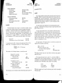
O u r i r r t e r e s ti n y o u r f l y i n g p l e a s u r eh a s n o t c e a s e dw i t h y o u r p u r c h a s eo f a C e s s n a . W o r l d w i d e , t h e C e s s n aD e a l e rO r g a n i z a t i o nb a c k e d b y t h e C e s s n aS e r v i c eD e p a r t m e n ts t a n d s r e a d y
t o s e r v ey o u . T h e f o l l o w i n g s e r v i c e sa r e o f f e r e d b y m o s t C e s s n aD e a l e r s :
T H E C E S S N AW A R R A N T Y - - l t i s d e s i g n e dt o p r o v i d e y o u w i t h t h e m o s t c o m p r e h e n s i v ec o v e r a g ep o s s i b l e :
No exclusions
a.
b.
C o v e r a g ei n c l u d e sp a r t s a n d l a b o r
A v a i l a b l ea t C e s s n aD e a l e r sw o r l d w i d e
c.
Best in the industry
d.
S p e c i f i c b e n e f i t s a n d p r o v i s i o n so f t h e w a r r a n t y p l u s o t h e r i m p o r t a n t b e n e f i t s f o r
y o u a r e c o n t a i n e d i n y o u r C u s t o m e r C a r e P r o g r a m b o o k s u p p l i e dw i t h y o u r a i r p l a n e .
W a r r a n t y s e r v i c ei s a v a i l a b l et o y o u a t a n y a u t h o r i z e d C e s s n aD e a l e r t h r o u g h o u t t h e
w o r l d u p o n p r e s e n t a t i o no f y o u r C u s t o m e r C a r e C a r d w h i c h e s t a b l i s h e ys o u r e l i g i b i l ity under the warranty.
F A C T O R Y T R A I N E D P E R S O N N E Lt o p r o v i d ey o u w i t h c o u r t e o u se x p e r t s e r v i c e .
F A C T O R Y A P P R O V E DS E R V I C E E O U I P M E N Tt o p r o v i d ey o u w i t h t h e m o s t
e f f i c i e n t a n d a c c u r a t ew o r k m a n s h i p p o s s i b l e .
OF CONTEI\.
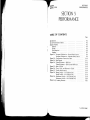
TABLE
OF CONTENTS
Welcome to the ranks of Cessnaowners! Your Cessnahas been designedand constructed to
g i v e y o u t h e m o s t i n p e r f o r m a n c e ,e c o n o m y , a n d c o m f o r t . l t i s o u r d e s i r et h a t y o u w i l l f i n d
f l y i n g i t , e i t h e r f o r b u s i n e s so r p l e a s u r e ,a p l e a s a n ta n d p r o f i t a b l e e x p e r i e n c e .
T h i s h a n d b o o k h a s b e e n p r e p a r e da s a g u i d e t o h e l p y o u g e t t h e m o s t p l e a s u r ea n d u t i l i t y
f r o m y o u r a i r p l a n e . l t c o n t a i n s i n f o r m a t i o n a b o u t y o u r C e s s n a ' se q u i p m e n t , o p e r a t i n g p r o c e d u r e s ,a n d p e r f o r m a n c e ;a n d s u g g e s t i o n sf o r i t s s e r v i c i n ga n d c a r e . W e u r g e y o u t o r e a d
it from cover to cover,and to refer to it frequently.
TABLE
SECTION
CENERAL
. 1
LIMITATIONS
. 2
EMERCENCY
PROCEDURES
3
NORMALPROCEDURES
.
4
PERFORMANCE
5
WEICHT& BALANCE/
EQUTPMENT
LIST.
6
AIRPLANE
& SYSTEMS
DESCRIPTIONS
.
AIRPLANE
HANDLINC,
SERVICE
& MAINTENANCE
.
SUPPLEMENTS
(OptionalSystemsDescription
& OperatingProcedures
)
A S T O C K O F G E N U I N E C E S S N AS E R V I C E P A R T S o n h a n d w h e n v o u n e e d t h e m .
T H E L A T E S T A U T H O R I T A T I V E I N F O R M A T I O N F O R S E R V I C I N GC E S S N A
A I R P L A N E S , s i n c eC e s s n aD e a l e r sh a v ea l l o f t h e S e r v i c eM a n u a l sa n d P a r t s
Catalogs,kept current by Service Letters and Service News Letters, published by
C e s s n aA i r c r a f t C o m p a n y .
I
W e u r g e a l l C e s s n ao w n e r s t o u s e t h e C e s s n aD e a l e rO r g a n i z a t i o nt o t h e f u l l e s t .
A c u r r e n t C e s s n aD e a l e r D i r e c t o r y a c c o m p a n i e sy o u r n e w a i r p l a n e . T h e D i r e c t o r y i s r e v i s e d
f r e q u e n t l y , a n d a c u r r e n t c o p y c a n b e o b t a i n e d f r o m y o u r C e s s n aD e a l e r . M a k e y o u r
D i r e c t o r y o n e o f y o u r c r o s s - c o u n t r yf l i g h t p l a n n i n g a i d s ; a w a r m w e l c o m e a w a i t s y o u a t
every CessnaDealer.
T h i s h a n d b o o k w i l l b e k e p t c u r r e n t b y S e r v i c eL e t t e r sp u b l i s h e db y C e s s n aA i r c r a f t
C o m p a n y . T h e s e a r e d i s t r i b u t e d t o C e s s n aD e a l e r sa n d t o t h o s e w h o s u b s c r i b e
t h r o u g h t h e O w n e r F o l l o w - U p S y s t e m . l f y o u a r e n o t r e c e i v i n gs u b s c r i p t i o ns e r v i c e ,
y o u w i l l w a n t t o k e e p i n t o u c h w i t h y o u r C e s s n aD e a l e rf o r i n f o r m a t i o n c o n c e r n i n g '
t h e c h a n g es t a t u s o f t h e h a n d b o o k . S u b s e q u e n tc h a n g e sw i l l b e m a d e i n t h e f o r m
o f s t i c k e r s . T h e s es h o u l d b e e x a m i n e da n d a t t a c h e dt o t h e a p p r o p r i a t ep a g e i n t h e
h a n d b o o k i m m e d i a t e l y a f t e r r e c e i p t ;t h e h a n d b o o k s h o u l d n o t b e u s e d f o r o p e r a t i o n a l p u r p o s e su n t i l i t h a s b e e n u p d a t e d t o a c u r r e n t s t a t u s .
iiil(iv
blank)
I
I
t_v
l'
I
f,r
CESSNA
MODEL I72M
SECl
GENE,
SECToN1
CENERAL
[]l
lri
I
',
I
1i
t1
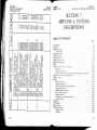
TABLE OF CONTENTS
Page
, ,)
i'
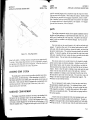
Three V i ew
Introducti on
D escri pti ve Dat a
Engine
Propeller
Fuel
oil
Maximum Certificated Weigh Lsj
Standard A irplane Weights
Cabin and Entry Dimensions .
Baggage Space and Entry Dimensions .
Specific Loadings.
Symbols, Abbreviations and Terminology
General Airspeed Terminology and Symbols .
Meteorological Terminology .
Engine Power Terminology
Airplane Performance and Flight Planning Terninology
Weight and Balance Terminology .
t-z
1- 3
1- 3
1-3
1-3
1-3
t-4
1-5
1-5
1-5
1-5
1-5
1-6
1,6
1-6
t-7
t-7
t-7
1-1
SECTION 1
GENERAL
CESSNA
MODEL I72i[/'[
CESSNA
MODEL I72\/I
SECTION 1
GENERAL
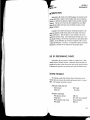
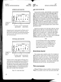
INTRODUCTION
This handbook contains 9 sections, and includes the material required
to be furnished to the pilot by CAR Part 3. It also contains supplemental
data supplied by Cessna Aircraft Company.
It
Section 1 provides basic data and information of general interest.
also contains definitions or explanations of symbols, abbreviations, and
terminology commonly used.
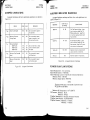
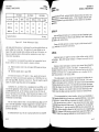
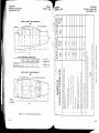
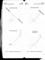
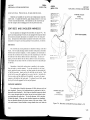
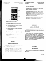
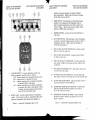
NOTES:
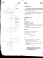
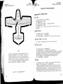
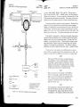
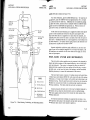
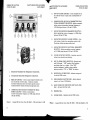
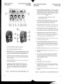
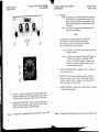
1.
Wing span shown with strobe lights
installed.
Maximum height shown with nose
gear depressed,dll tires and nose
strut properly Inflated, aod flashing
beacon installed.
3
Wheel ' ase length is 65,,.
Propeller ground clearance is I 1 3/4,,.
5.
Wing area rs I 74 square feet.
6.
Minrmum turntnq rdd,llst*l)rvut point
to ,ruthoard wrrq t pl r, ? l' 5'-".
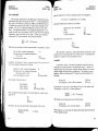
D E S C R I P T I V ED A T A
ENGINE
Number of Engines: 1.
Engine Manufacburer: Avco Lycoming.
Engine Model Number: 0-320-E2D.
Engine Type: Normally-aspirated, direct-drive, air-cooled, horizontallyopposed, carburetor equipped. four-cylinder e n s i n e w i t h 3 2 0 c u . i n .
displacement.
Horsepower Rating ancl Engine Speed: 150 rated BHP at 2700 RPM.
PROPELLER
Propeller Manufacturer: McCauley Accessory Division.
Propeller Model Number: 1C160/DTM?553.
Number of Blades: 2.
Propeller Diameter, Maximum: 75 inches.
Minimum: 74 inches.
Propeller Type: Fixed pitch.
FUEI
FueI Grade (and color):_11_Q18?Minirnum Grade Aviation Fuel (red).
Alternate fuels which are also approved are:
100/130 Low Lead AVGAS (green). (Maximum lead content of 2 cc
per gallon. )
100/130 Aviation Grade Fuer (green). (Maximum read content of
4.6 cc per gallon. )
6'-3"i AX.
lr-
l_
8'_;
Figure 1-1. Three View
NOTE
When substihurting a higher octane fuel, low lead AVGAS
100 should be used whenever possible since it will result
in less lead contamination of the engine.
1-3
_CESSNA
MODEL I72M
Fuel Capacity:
Standard Tanks:
Total Capacity: 42 gallons.
Total Capacity Each Tank: 21 gallons.
Total Usable: 38 gallons.
' Long
Range Tanks:
Total Capacity: 52 gallons.
Total Capacity Each Tank: 26 gallons.
Total Usable: 48 gallons.
NOTE
To ensure rnaximum fuel capacity when refueling, place
the fuel selector valve in either LEFT or RIGHT position to prevent cross-feeding.
II
CESSNA
MODEL T72M
SECTION 1
GENERAL
, U A X I , UU , V IC E R T I F I C A T EW
D EIGHTS
Takeoff, Noi'mal Category: 2300 lbs.
Utility Category: 2000 lbs.
Landing, Normal Category: 2300 tbs.
Utility Category: 2000 lbs.
Weight in BaggageCompartment, Normal Category:
BaggageArea I (or passenger on childts seat)-Station82 to 108:
120 lbs. Seenote below.
BaggageArea 2 -Station 108 to 142: 50 lbs. See note below.
NOTE
The maximum combinedweight capacity for baggageareas
1 and 2 is 120 lbs.
Weight in BaggageCompartment, Utility Category: In this category, the
baggagecompartment and rear seat must not be occupied.
orr
OiI Grade (Specification) :
MIL-L-6082 Aviation Grade Straight Mineral Oil: Use to replenish
supply during first 25 hours and at the first 25-hour oil change.
Continue to use until a total of 50 hours has accumulated or oil
consumption has stabilized.
STANDAR D AIRPLANE WEIGHIS
Standarcl Empty Weight, Skyhawk:
Skyhawk II:
1387 lbs.
1412 lbs.
Maximum Useful Load:
NOTE
The airplane was delivered from the factory with a corrosion preventive aircra-ft engine oil. This oil should be
drained after the first 25 hours of operation.
,[,
n'trL-L-22851 Ashless Dispersant Oit: This oil must be used after
first 50 hours or oiI consumptionhas stabillzea-RecommendedViscosity For TemperabureRange:
SAE 50 abov e 16" C (6 0 " F ).
S A E 1 0 W 3 0o r S A E 3 0 b e t w e e n- 1 8 " C ( 0 " F ) a n d 2 l ' C ( ? 0 ' F ) .
SAE 10W 30or S A E 2 0 b e l o w -1 2 ' C (1 0 " F ).
NOTE
Multi-viscosity oil with a range of SAE 10W30is recommendedfor improved starting in cold weather.
oiI Capacity:
Sump: B Quarts.
Total: 9 Quarts.
t-4
Normal Category
ffi
Skyhawk:
Skyhawk II:
888 lbs.
588 lbs.
CABIN AND ENTRYDIAAENSIONS
Detailed dimensions of the cabin interior
illustrated in Section 6.
and entry door openings are
B A G G A G E S P A C EA N D E N T R Y D t ' U E N S I O N S
Dimensions of the baggage area and baggage door opening are
trated in detail in Section 6.
S P E C I F I CT O A D I N G S
Wing Loading:
Power Loading:
13.2 lbs. /sq.ft.
15.3 lbs. /hp.
1-5
SECTION 1
GENERAL
CESSNA
MODEL I72NI
SYMBOLS, ABBREVIATIONS AND TERMINOLOGY
G E N E R A TA I R S P E E DI E R ' U I N O t O G Y A N D S Y f i I B O t S
KCA S
Knots Calibrated Airspeed is indicated airspeed corrected
error and expressed in knots.
Knots calibrated airspeed is equal to KTAS in standard atmosphere at sea level.
KIA S
Knots Indicated Airspeed is the speed shown on the airspeed
in knots.
KTA S
Knots True Airspeed is the airspeed expressed in knots relwhich is KCAS corrected for altibude
ffiir
and temperature.
VA
Manelyering Slged is the maximum speed at which you may
use abrupt control travel.
vFn
Maximum Flap Extended 9peed is the highest speed permissible with wing flaps in a prescribed extended position.
vNo
Maximum Structural Cruising Speed is the speed that should
, then only with caution.
vNn
Neve{ Exce?d Speed is the speed limit that may not be exceeded at any time.
VS
uto
VX
VY
Stailing Speed or the minimum
the airplane is controllable.
steady flight_gpee9 at which
Stalling Speed or the minimum -steady flight speed at which
the airplane is controllable in the landing configuration at
the most forward center of gravity.
Best Angle-of-Climb Speed is the speed which results in the
greatest gain of altitude in a given horizontal distance.
Best Rate-of-Cttnqb llpeect is the speed which results in the
a given time.
, UE T E O R Ot O G I C A T T E Rf r lI N O T O G Y
OAT
Outside Air Temperature is the free air static temperahrre.
degrees Celsius (formerly Centigrade) or degrees Fahrenheit.
SECTION 1
GENERAL
CESSNA
MODEL I72}/I
Standard
Temperature
StandardTemperature is 15"C at sea level pressure altitude
each 1000 feet of altitude.
ffior
P ressure
Altitude
Pressure Altitude is the altitude read from an altimeter
subscale has been set to 29.92 inches
ffiic
of mer cur y ( 1013m b) .
E N G I N EP O W E R T E R f r I I N O t O G Y
BHP
Bra]<eHolselpwer is the power developed by the engine'
RPM
Revolutions Per Minute is engine speed.
Static
RPM
Static RPM is engine speed attained during a full-throttle engine runup when the airplane is on the ground and stationary.
A I R P L A N E P E R F O R ' N A N C EA N D F L I G H I P L A N N I N G T E R I t , l I N O L O G Y
Demonstrated Crosswind Velocity is the velocity of the crosse control of the airPlane
during takeoff and landing was actually demonstrated during
certification tests. The value shown iS not considered to be
Demonstrated
Crosswind
Velocity
limiting.
Usable Fuel
ULabIe ILeI is the fuel available for f tight planning.
Unusable
Fuel
Unqsable FuSl is the quantity of fuel that can not be saf ely
used in flight.
GpH
GaIIons Pgr Hour is the amount of fuel (in gallons) consumed
per hour.
NMPG
Nautical Miles Per Gallon is the distance (in nautical miles)
gallon of fuel consumed at a sPecific engine power setting and./or flight configuration.
g
g is acceleration due to gravitY.
WEIGHI
AND
BATANCE TER'NINOLOGY
Reference Datum is an imaginary vertical plane from which
Reference
DatumffitancesaremeaSuredforbalancepurpoSes.
Station
Station is a location along the airplane fuselage given in
Eirn's of the distance from the reference datum.
t-7
SECTION 1
GENERAL
CESSNA
MODEL T72NI
Arm
Arm is the horizontal distance from the reference datum to
TFcenter of gravity (C. G. ) of an item.
Mo m ent
Momegl is the product of the weight of an item multiplied by
(Mornent divided by the constant 1000 is used in
its arm.
this handbook to simplify balance calculations bv reducing
the number of digits. )
Center of
Gravity
( c . c .)
Center of Gravity is the point at which an airplane, or equipm@ce
if suspended. Its distance from the
reference daturu is found by dividing the total nroment by the
total weight of the airplane.
A rrr
Center of GravityArnt is the arm olrtained by adding the
tfpianF;-indFidGT-moments
and dividing the sum by the
total weight.
C. G.
Limits
Center of Gravity Limits are the extreme center of gravity
Iocatibns wiTfiir*fficlr the airplane nrust be oneratecl at a
given weighl""
Standarci
Enrptv
Weight
the weigirr ol a standard airplane.
!@is
including unusable fr-rel, full cperatinll fiuids and full engine
oiI.
Basic Emptll Basi-c Erypty Weig'ht is the standarci cillprv weight plus the
Weighi
weight of optional equipment"
Uselul
Load
Llseful Load is the difference bet',veen takeoff weisht and the
6asic enrptn weighr.
Gross
(Loaded)
Weight
G r o s s ( L o a d e d ) W e i e h t i s t h e ioacled weight of the airplane.
Maximum
Takeoff
Weight
Maximum TakeoflWeight
Maximum
Landing
Weight
Maximum Landing lleight is the maximum weight approved
Tare
T at e is th e w e i g h t o f c h o c k s , b l o c ks, stands, etc. used
when weighing an airplane, and is included in the scale readings. Tare is deductedfrom the scale readins to obtain the
acbual (net) airplane weight.
1-B
SECTION 2
LIMITATIONS
CESSNA
MODEL 172M
SECTION2
LIMITATIONS
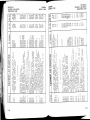
TABLE OF CONTENTS
Introduction
Airspeed Limitations
Airspeed Indicator Markings
Power Plant Limitations
Power Plant Instrument Markings
Weight Limits
Normal CategorS' .
Utility Category
Center of Gravity Limits
Normal Category .
Utility Categor.v
Maneuver Limits
Normal Category .
Utility Category
Flight Load Factor Limits
Normal Categor5:
Utility Category
Kinds of Operation Limits
FueI Limitations
Placards
Page
2-3
2-4
2-5
2-5
2- e',
2-6
2-6
.)i
2-1
2- 7
atn
A-"
Z-
|
oi
L-l
2-7
Qr,
a-6
Oal
z-a
.
2-9
2-9
2-74
is the maximum weight approved
run.
2-l/ (2-2 blank)
SECTION 2
LIMITA TIONS
CESSNA
MODEL I72M
INTRODUCTION
instrument markings, and
Section 2 includes operating limitations,
basic placards necessary for the sa.fe operation of the airplane, its engine,
standard systems and standard equipment. The limitations included in
this section have been approved by the Federal Aviation Administration.
When applicable, limitations associated with optional systems or equipment are included in Section 9.
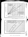
NC,TE
The airspeeds listed in the Airspeed Limitations chart
(figure 2-1) and the Airspeed Indicator Markings chart
(figure 2-2) are based on Airspeed Calibration data shown
in Section 5 with the normal static source. If the alternate static source is being used, ample margins should
be observed to allow for the airspeed calibration variations between the normal and alternate static sources as
shown in Section 5.
Your Cessna is certificated under FAA Type Certificate No. 3A12 as
Cessna Model No. 172M.
2-3
CESSNA
MOD E L 172M
SECTION 2
LIMITATIONS
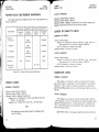
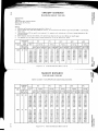
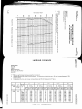
A I R S P E E DL I M I T A T I O N S
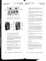
Airspeed limitations
fi,gure 2-1.
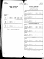
A I R S P E E DI N D I C A T O R ,M A R K I N G S
and their operational significance are shown in
SPEED
KCAS
KIAS
N e v e r E x c e e dS p e e d
158
160
D o n o t e x c e e dt h i s s p e e di n
any operation.
Vruo
Maximum Structural
C r ui s i n g S p e e d
126
128
D o n o t e x c e e dt h i s s p e e d
except in smooth air, and
then only with caution.
VrE
Maneuvering
Speed:
2300 Pounds
1950 Pounds
1600 Pounds
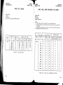
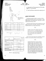
AirsPeed indicator markings and their color code significance are
shown in figure 2-2.
MARKING
K I A SV A L U E
OR RANGE
WhiteArc
4 1- 8 5
GreenArc
47 - 128
REMARKS
VruE
V4
96
BB
BO
97
B9
BO
Do not make full or abrupt
c o n t r o l m o v e m e n t sa b o v e
this speed.
Yellow Arc
Maximum Flap Extended
Speed
B6
B5
D o n o t e x c e e dt h i s s p e e d
with flapsdown.
Red Line
Maximum Window Open
Speed
158
Frgure 2-1.
SECTION 2
LIMITATIONS
CESSNA
MODEL I72}/n
160
D o n o t e x c e e dt h i s s o e e d
with windowsopen.
Airspeed Limitations
S I G NI F I C A N C E
Full Flap Operating Range. Lgy.et
- ildi m
i oiitnigs m a x i m u m w e i g h t V g o i n
cbnfiguration. uppei limit
i s m a x i m u m s p e e dp e r m i s s i b l ew i t h
flaps extended.
Normal Operating Range. _L*g-*.-"I
limit is maximum weight Vg with
f l a p sr e t r a c t e d . U p p e r l i m i t i s m a x i m u m s t r u c t u r a lc r u i s i n gs p e e d .
1 2 8- 1 6 0
O p e r a t i o n sm u s t b e g o n d u c t e d w i t h
c a u t i o na n d o n l y i n s m o o t h a i r .
160
M a x i m u m s p e e df o r a l l o p e r a t i o n s .
Figure 2-2.
Airspeed Indicator Markings
POWER PTANT LIMITATIONS
Engine Manufacburer: Avco Lycoming.
Engine Model Number: O-320-82D.
Engine Operating L.imits for Takeoff and Continuous Operations:
Maximum Power: 150 BHP.
Maximum Engine Speed: 2700 RPM.
NOTE
Jhe- static RPM range at full throttle
.6Ji- zsooto z42oRPM.
(carburetor
heat
Maximum Oil Temperature: llBoC (245'F).
OiI Pressure, Minimum:
2b psi.
Maximum: 100 psi.
Propeller Manufacturer: McCauley Accessory Division.
Propeller Model Number: 1Cl60/DTM?553.
Propeller Diameter, Maximum: ?b inches.
Minimum:
74 inches.
2-5
CESSI\A
MODEL I72NI
SECTION 2
LIMITATIONS
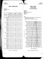
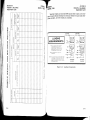
INSTRUMENT
markings
and their color code significance
are
RED LINE
G R E E NA R C
Y E L L O WA R C
RED LINE
MINIMUM
LIMIT
NORMAL
O P ER A T I N G
CAUTION
RANGE
MAXIMUM
LIMIT
Maximum Takeoff Weight: 2000 lbs.
Maximum Landing Weight: 2000 lbs.
Maximum Weight in BaggageCompartment: In the utility category, the
baggagecompartment and rear seat must not be occupied.
C E N T E RO F G R A V I T Y L I M I T S
NOR'NAt
Tachometer
At Sea Level
2200 2 5 O OR P M
2 7 O OR P M
At 5000 Ft.
2200 2600 RPM
2 7 O OR P M
A t 1 0 . 0 0 0F t .
2200 2 7 O OR P M
2 7 O OR P M
25 psi
Oil Pressure
2450F
Figure 2-3.
1 0 0p s i
60-90 psi
150 to 5oC
C a r b u r e t o rA i r
T e m p e r a t ur e
CATEGORY
Center of GravitY Range:
F o r w a r d : 3 5 . 0 i n c h e s a f t o f d a t u m a t 1 9 5 0 l b s . or less, with str;,ru"i'it
line variation to 38. 5 inches aft of dabum at 2 3 0 0 l b s .
Aft: 47. 3 inches aft of datum at all weights.
Datum: Front face of firewall.
lelgrence
UTILITYCATEGORY
10oo-2450F
Oil Temperature
SECTION 2
LIMITATIONS
UTITIIY CATEGORY
POWER PLANT INSTRUMENTMARKINGS
Power plant instrument
shown in figure 2-3.
CESSNA
MODEL 772M
Power Plant Instrument Markings
Center of Gravity Range:
Forward: 35.0 inches aft of datum at 1950 lbs. or less, with straigtrt
line variation to 35. 5 inches aft of datum at 2000 lbs.
Aft: 40. 5 inches aft of datum at aII weights.
Reference Datum: Front face of firer.vall
MANEUVER LIMITS
NOR'YTAt CATEGO RY
WEIGHT LIMITS
NORAAAL CATEGORY
Maximum Takeoff Weight: 2300 lbs.
Maximum Landing Weight: 2300 lbs.
Maximum Weight in Baggage Compartment:
Baggage Area 1 (or passenger on child's seat)-station 82 to 108:
120 lbs. See note below.
eagg;ge Area 2 -Station 108 to 142: 50 lbs. See note below.
NOTE
The maximum combined weight capacity for baggage areas
1 and 2 is 120 lbs.
2-6
This airplane is certificated in lrcth the normal and utili.ty category.
JIt_" normal category is applicable to aircraft intendecl for non-aerobatic
operations.
These include any maneuvers incidental to norrnal flying,
- stalls (except whip stalls) ancl turns in which the angle of bank is not nlore
*Than
60".
UTIIIIY CATEGORY
This airplane is not designecl for purely aerobatic flight. However,
in the acquisition of various certificates such as commercial pilot, instrument pilot and flight instructor, certain maneuvers are required by the
FAA. All of these maneuvers are permitted in this airplane when operated in the utility category.
In the utility category, the baggage compartment and rear seat must
2-7
SECTION 2
LIMITATIONS
not be occupied.
*5d'betow
i
CESSNA
MODEL 172M
No aerobatic maneuvers are approved except those list-
MANEUVER
RECOMMENDEDENTRY SPEED*
Chandelles .
Lazy Eights
Steep Turns
Spins
Stalls (Except Whip Stalls).
105 knots
95 knots
Slow Deceleration
Slow Deceleration
SECTION 2
LIMITATIONS
iff#'i nz'
KINDS OF O PERATION LIMITS
The airplane is equipped for day VFR and may be equipped for night
FAR Part 91 establishes the minimum reVFR and/or IFR operations.
for these operations. The referequipment
and
instrumentation
ouired
placard reence to types of flight operations on the operating limitations
time
of
Airworthiness
Certificate
issuance.
the
at
installed
equipment
iiects
Flight into known icing conditions is prohibited.
*Abrupt use of the controls is prohibited above 9? knots.
Aerobatics that may impose high loads should not be attempted. The
important thing to bear in mind in flight maneuvers is that the airplane is
clean in aerodynamic design and will build up speed quickly with the nose
down. Proper speed control is an essential requirement for execution of
any rraneuver, and care should always be exercised to avoid excessive
speed which in turn can inrpose excessive loads. In the execution of all
maneuvers, avoid abrupt use of controls. Intentional spins with flaps extended are prohibited.
FUEt LIMITATIONS
2 Standard Tanks: 2l U. S. gallons each.
Total Fuel: 42 U. S. gallons.
Usable Fuel (all flight conditions): 3B U. S. gallons.
Unusable F\rel: 4.0 U. S. gallor's.
2 Long Range Tanks: 26 U. S. gallons each.
-Total"
Fridl: 52 U. S. gallons.
-Us_ableFuel (all flight conditions): 48 U. S. gallons.
Unusable Fuel: 4. 0 U. S. sa1lons.
NOTE
To ensure maximum fuel capacity when refueling, place
the fuel selector valve in either LEFT or RIGHT position to prevent cross-feeding.
FLIGHT LOAD FACTOR LIMITS
N O R ' \ A A LC A I E G O R Y
Flight Loacj Factors (Gross Weight - 2300 lbs. )
* Flaps Up
*Flaps Down .
NOTE
+3.8g, -L.52g
+ 3.0g
*The design load factors are 150%of the above, and in all
cases, the structure meets or exceeds design loads.
U T I L I T YC A I E G O R Y
Flight Load Factors (Gross Weight - 2000 lbs. )
*Flaps Up
x F laps Dow n .
+4.49, -1.?6g
+ 3.0g
*The design load factors are l507o of the above, and in all
cases, the strucbure meets or exceeds design loads.
2-8
Takeoff and land with the fuel selector valve handle in
the BOTH position.
FueI Grade (and Color) : AO/gl Minimurn Grade Aviation F\rel (red).
Alternate fuels which are also approved are:
t00/130 Low Lead AVGAS (green). (tvtaximum lead content of 2 c c
per gallon. )
700/130 Aviation Grade FueI (green). (Maximum leacl content of
4. 6 cc per gallon. )
NOTE
When substituting a higher octane fuel, low lead AVGAS
L00 should be used whenever possible since it will result
in less lead contamination of the engine.
2-9
CESSNA
MODEL 1?2M
SECTION 2
LIMITATIONS
SECTION 2
LIMITATIONS
L7zl/n
PLACARDS
Forward of fuel selector valve:
The following information
individual placards.
is displayed in the form of composite or
entry,
(1) In full view of the pilot: (The "DAY-NIGHT-VFR-IFR"
shown on the example below, will vary as the airplane is equiPPed.)
(3) On the fuel selector valve (standard tanks):
This airplane must be operated in compliance with the operating
Iimitations as stated in the form of placards, markings, and
manua]s.
B OTH - 38 G AL. ALL FLI G HT ATTI TUDES
LE FT - 19 G AL. LEVEL FLI G HT O NLY
R IGHT - 19 G AL. LEVEL FLI G HT O NLY
OFF
-Nt\xIMUMS
I\4ANEWEzuNG SPEED (IAS)
GROSS WEIGHT
FLIGHT LOAD FACTOR
Utility Categorv
97 KNOTS
2000 lbs.
Normal Category
97 KNOTS.
2300 lbs.
FlapsUp
Flaps Down
On the fuel selector valve (long range tanks):
+ 3 .B , - L . 5 2
+ 3 .0
BOTH - 48 GAL. ALL FLIGHT ATTITUDES
LEFT - 24 GAL. LEVEL FLIGHT ONLY
RIGHT - 24 GAL. LEVEL FLIGHT ONLY
OFF
Normal Category - No acrobatic nraneuvers incluclittg' spins
approved.
Utility Category - Baggage colnpartment and r-ear seat must
not be occupied.
NO ACROBATIC MANEIIV-ERS APPROVED
EXCEPT THOSE LISTED BELOW
Maneuver
Recm. Entry Speed
ffies.
-
-mdGors
Lazy Eights
. 105 knots
SteepTurns
95 knots
Maneuver
Stalls (except
whip sta1ls) SIow Deceleratiot;
Altitude loss in stall recovery -- 180 feet.
Abrupt use of controls prohibited above 97 knots.
Spin Recovery: opposite rudder - forward elevator - neutralize
controls. Intentional spins with flaps extended are prohibited.
Flight into known icing conditions prohibited. This airplane is
certified for the follorving flight operations as of date of originai
airworthiness certificate :
2 - 10
Near fuel tank filler
cap (standard tanks):
Rer:m. Entry Speed
Sins l_'.;ffi
DAY-MGHT-VFR-IFR
(4)
FUE L
80/87 MrN. GRADE AVTATTONGASOLTNE
CAP. 21 U. S. C"AL.
Near fuel tank filler
cap (long range tanks):
FUEL
80/87 MrN. GRADE AVTATTONGASOLTNE
CAP. 26 U. S. G AL.
2-tI
SECTION 2
LIMITATIONS
(5)
Near flap indicator:
AVOID SLIPS WITH FLAPS EXTENDED
(6)
SECTION 3
EMERGENCY PROCEDURES
C ESSNA
MODEL 1?2M
SECToN3
PROCEDURES
EMERCENCY
In baggage compartment:
120 POUNDSMAXIMUM
BAGGAGEAND/OR ATIXiTJARYPASSENGER
FORWARDOF BAGGAGEDOOR LATCH
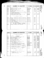
TABIE OF CONTENTS
50 POUNDSMAXIMUM
BAGGAGEAFT OF BAGGAGEDOOR LATCH
Introduction
Airspeeds For Safe Operation
Page
MAXIMUM 120 POUNDSCOMBINED
FOR ADDITIONAL LOADING INSTRUCTIONS
SEE WEIGHT AND BAI.ANCE DATA
(7)
On the instrument panel near over-voltage light:
H IGH VOL T A G E
3-3
3-3
OPERATIONA L CHECKLISTS
Engine Failures
Engine Failure During Takeoff Rrn .
Engine Failure Immediately After Takeoff .
Engine Failure During Flight
Forced Landings
Emergency Landing Without Engine Power
Precautionary Landing With Engine Power
Ditching .
Fires
Engine Fire During Start On Ground
Engine Fire In Flight .
Electrical Fire In Flight
Cabin Fire
Wing Fire
I r'r no
Inadvertent Icing Encounter
static source Blockage (Erroneous Instrument Reading
Suspected) .
_
Landing With A Flat Main Tire
Electrical Power Supply System MaUunctions
Over-Voltage Li[ht Illuminates
Ammeter Shows bischarge
A MPLIFIED
Ergine Failure .
Forcedlandings.
2-12
.
. . . .
. .
3,3
3-3
3-3
3-4
B-4
B-4
3-4
3-b
3-b
3-5
3-6
3-6
3-6
3-7
3-7
3-?
3-g
3_B
3-g
3-g
3_g
PROCEDIJRES
3_g
3_10
3-1
SECTION 3
EMERGENCY PROCEDURES
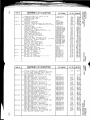
TABLE OF CONTENIS (Continued)
INTRODUCTION
Page
Landing Without Elevator Control
Fires
Emergency Operation In Clouds (Vacuum System Failure).
Executing A 180" Turn In Clouds .
Emergency Descent Through Clouds
Recovery From A Spiral Dive
Flight In Icing Conditions
Static Source Blocked
Spins
Rough Engine Operation Or Loss Of Power
Carburetor Icing
Spark PIug Fouling
Magneto Malfunction
Low Oil Pressure
Electrical Power Supply System Malfunctions
Excessive Rate Of Charge .
Insufficient Rate Of Charee
SECTION 3
EMERGENCY PROCEDURES
CESSNA
MODEL ITZM
3-10
3- 10
3 -1 1
3 -1 1
3-11
3 -1 2
3 -1 2
3 -1 2
3 -1 3
3 -1 3
3 -1 3
3- 14
3- 14
3-14
3 -1 5
3-15
3 -1 5
Section 3 provides checklist and amplified procedures for coping with
Emergencies caused by airplane or engine
emergencies that may occur.
rare
if proper preflight inspections and mainextremely
are
maLfunctions
Enroute weather emergencies can be minimized
tenance are practiced.
or eliminated by careful flight planning and good judgement when unexpected weather is encountered. However, should an emergency arise the basic
zuidelines described in this section should be considered and applied as
Emergency procedures associated
to correct the problem.
iu""rr"ty
with the ELT and other optional systems can be found in Section 9.
A I R S P E E D SF O R S A F E O P E R A T I O N
Engine Failure After Takeoff :
Wing Flaps Up
Wing Flaps Down .
Maneuvering Speed:
2300 Lbs
1950 Lbs
1600 Lbs
Maximum Glide:
2300 Lbs
Precautionar.y Landing With Engine Power
Landing Without Engine Power:
Wing Flaps Up
Wing Flaps Down .
65 I(IAS
60 KIAS
97 I(IAS
89 KIAS
80 I(IAS
65 I(IAS
60 KIAS
6b I(IAS
60 I(IAS
O P E R A T I O N A TC H E C K L I S T S
ENGINE FAILURES
E N G I N EF A I T U R ED U R I N G I A K E O F F R U N
(1)
(2)
(q)
t4)
(5)
Throtile -- rDLE.
Brakes -- Appl,y.
wing Flaps -- RETRACT.
Mixture -- IDLE CUT-OFF.
Ignition Switch -- OFF.
E N G I N EF A I [ U R EI A A ' U E D I A I E TAYF I E R I A K E O F F
(1) Airspeed -- 6b KrAS (ftaps
Up).
60 KIAS (flaps DOWN).
3-3
SECTION 3
EMERGENCY PROCEDURES
(2)
(3)
(4)
(5)
(6)
CESSNA
MOD E L 172M
Mixture -- IDLE CUT-OFF.
FueI Selector Valve -- OFF.
Ignition Switch -- OFF.
Wing Flaps -- AS REQUIRED.
Master Switch -- OFF.
E N G I N EF A I T U R ED U R I N G F L I G H T
( 1)
(2)
(3)
(4)
(5)
(6)
A ir s pee d -- 6 5 K IAS .
Carburetor Heat -- ON.
Fuel Selector Valve -- BOTH.
Mixture -- RICH.
Ignition Switch -- BOTH (or START if propeller is stopped).
Primer -- IN and LOCKED.
FORCEDLANDINGS
E , V \ E R G E N CLYA N D I N G W I I H O U T E N G I N E P O W E R
( 1) A ir s pe e d -- 6 5 I(IAS (fl a p s U P).
60 KIAS (flaps DOWN).
2) M i x t u r e - - I D L E C U T - O F F .
3 ) Fuei Selector Valve -- OFF.
4 ) Ignition Switch -- OFF.
Wing Flaps -- AS REQUIRED (40' recommended).
6 ) Master Switch -- OFF.
7 ) Doors -- UNTATCH PRIOR TO TOUCHDOWN.
B ) Touchdown -- SLIGHTLY TAIL LOW.
e ) Brakes -- APPLY HEAVILY.
c)
PRECAUTIONART
Y A N D I N G W I T H E N G I N EP O W E R
(1) Wing Flaps -- 20".
( Z ) A i r s B e e d- - 6 0 K I A S .
(3) selected Field -- FLY ovER, noting terrain and obstructions,
then retract flaps upon reaching a safe altitude and airspeed.
(4) Radio and Electrical Switches -- OFF.
(5) Wing Flaps -- 40" (on final approach).
( 6) A ir s pe e d -- 6 0 K IAS .
( 7) M as t e r Sw i tc h -- OF F .
(8) Doors -- UNTATCH PRIOR TO TOUCHDOWN.
(9) Touchdown-- SLIGHTLY TAIL LOW.
(10) Ignition Switch -- OFF.
( 11) B r ak es -- AP PL Y H E AV IL Y.
SECTION 3
EMERGENCY PROCEDURES
ffj'ei'fLT*M
DITCHING
(1) Radio -- TRANSMIT MAYDAY on 121. 5 MHz, giving location
and intentions.
(2) Heavy Objects (in baggage area) -- SECURE or JETTISON.
(3) Flaps -' 20o - 40o
(4) Power -- ESTABLISH 300 FTIMIN DESCENT at 55 KIAS.
(5) Approach -- High Winds, Heavy Seas -- INTO TIm WIND.
Light Winds, Heavy Swells -- PARALLEL
SWELLS.
TO
NCrI E
If no power is available, approach at 65 KIAS with flaps
up or at 60 KIAS with 10o flaps.
(6) Cabin Doors -- UNIATCH.
(7) Touchdown -- LEVEL ATTITUDE AT ESTABLISHED DESCENT.
(8) Face -- CUSHION at Louchdown with folcled coat or seat cushion.
(9) Airplane -- EVACUATE through cabin doors. If necessary,
open window and flood cabin to equalize pressure so doors can be
opened.
(10) Life Vests and Raft -' INFL,ATE.
FIRES
E N G I N EF I R ED U R I N G S T A R TO N G R O U N D
(1) Cranking -- CONTINUE, to get a start which would suck the
flames and accumulated fuel through the carburetor and into the engine.
If engine starts:
(2) Power -- 1?00 RPM for a few minutes.
(3) Engine -- SHUTDOWNand inspect for damage.
If engine fails to start:
(4)
(Sl
(6)
(7)
not
(8)
Throtile -- FULL OPEN.
Mixture -- rDLE CUT-OFF.
Cranking -- CONTINUE for two or three minutes.
Fire Exlinguisher -- OBTAIN (have ground attendants obtain if
installed).
Engine -- SECURE.
&. Master Switch -- OFF.
3-5
SECTION 3
EMERGENCY PROCEDURES
CESSNA
MOD E L 1?2M
b.
Ignition Switch -- OFF.
FueI Shutoff Valve -- OFF.
c.
(9) Fire -- EXTINGUISH using fire extinguisher, seat cushion, wool
blanket, or dirt.
If practical trv to remove carburetor air filter if it
is ablaze.
(10) Fire Damage -- INSPECT, repair clamage or replace damaged
components or wiring before conducting another flight.
SECTION 3
EMERGENCY PROCEDURES
cEssrilA
lrloppl,
l72M
(4) Land the airplane as soon as possible to inspect for damage.
WING FIRE
( 1 ) Navigation Light Switch -- OFF.
( 2 ) Pitot Heat Switch (if installed) -- OFF.
NOTE
E N G I N E F I R EI N F L I G H T
(1) Mixture -- IDLE CUT-OFF.
(2) F\rel Selector Valve -- OFF.
(3) Master Switch -- OFF.
(4) Cabin Heat and Air -- OFF (except overhead vents).
(5) Airspeed -- 100 KIAS (If fire is not extinguished, increase glide
speed to find an airspeed which will provide an incombustible mixture).
(6) Forced Landing -- EXECUTE (as described in Emergency Landing Without Engine Power).
Perform a sideslip to keep the flames away from the
fuel tank and cabin, and land as soon as possible using
flaps only as required for fina-I approach and touchdown.
I C I NG
I N A D V E R T E N ITC I N G E N C O U N I E R
E L E C T RI C A L F I RE I N F L I GH T
(1) Master Srvitch -- OFF.
(2) AII Other Switches (except ignition switch) -- OFF.
(3) Vents/Cabin Air/Heat -- CLOSED.
(4) Fire Extinguisher -- ACTIVATE (if available).
If fire appears out and electrical
of flight:
power is necessary for continuance
(5) Master Switch -- ON.
(6) Circuit Breakers -- CHECK for faulty circuit, do not reset.
(7) Radio/Electrical Switches -- ON one at a time, with delay after
each until short circuit is localized.
(B) Vents/Cabin Air/Heat -- OPEN when it is ascertained that fire
is completely extinguished.
CABIN FIRE
(1) Master Switch -- OFF.
(2) Vents/Cabin Air/Heat -- CLOSED (to avoid drafts).
(3) Fire Extinguisher -- ACTIVATE (if available).
WARNING
After discharging an extinguisher
ventilate the cabin.
within a closed cabin,
(1) Turn pitot heat switch ON (if installed).
(2) Turn back or change altitude to obtain an ortside air temperature
that is less conducive to icing.
(3) Pull cabin heat control full out and open defroster outlet to obtain
ma:<imumwindshield defroster airflow. Adjust cabin air control to
get maximum defroster heat and airflow.
(4) Open the throttle to increase engine speed and minimize ice
build-up on propeller blades.
(5) Watch for signs of carburetor air filter ice and apply carburetor
heat as required. An unexplained loss in engine speed could be caused
by carburetor ice or air intake filter ice. Lean the mixture for maximum RPM if carburetor heat is used continuously.
(6) Plan a landing at the nearest airport. With an extremely rapid
ice build-up, select a suitable "off airport" landing site.
(?) With an ice accumulation of t/a iich or more on the wing leading
e-dges,be prepared for significantly higher stall speed.
(8) Leave wing flaps retracted. With a severe ice build-up on the
horizontal tail, the change in wing wake airflow direction caused by
YinS flap extension could result in a loss of elevator effectiveness.
!9) open left window and, if practical, scrape ice from a portion of
. the windshield for visibifity in the bnding approach
(10) Perform a landing approach using a forward slip, if necessary,
for improved visibiht!.
,
(11)
Approach at 65 to zs KIAS, dependingupon the amount of the
_accumulation.
(12) Perform a landing
in level attitude.
3-7
SECTION 3
EMERGENCY
CESS}IA
MODEL 172M
PROCEDURES
ff## LT'M
S T A T I C S O U R , C EB L O C K A G E
{Erroneous Instrument Reoding Suspected)
(1) Alternate Static Source Valve -- PULL ON.
(2) Airspeed -- Consult appropriate calibration tables in Section b.
LANDING WITH A FLAT MAIN TIRE
(1) Approach -- NORMAL.
(2) Touchdown -- GOOD TIRE FIRST,
Iong as possible.
hold airplane off flat tire as
E L E C T R I C APTO W E R S U P P L YS Y S T E MM A L F U N C T I O N S
O V E R - V O t T A G E L I G H T I T L UN A I N A T E S
( 1 ) Master Switch -- OFF (both sides).
( 2 ) Master Switch -- ON.
( 3 ) Over-Voltage Light -- OFF.
If over-voltage
(4)
light illuminates
Flight -- TERMINATE
again:
AMPLIFIED PROCEDURES
E N G T N EF A I L U R E
If an engine failure occurs during the takeoff run, the most important
Those extra
thine to do is stop the airplane on the remaining runway.
provide
during
a
failure
of this
added
safety
will
checklist
the
itern,s on
type.
prompt lowering of the nose to maintain airspeed and establish a
elide attitude is the first response to an engine failure after takeoff . In
most cases, the landing should be planned straight ahead with only small
Altitude and airspeed are selchanges in direction to avoid obstructions.
dom sufficient to execute a 180' gliding turn necessary to return to the
runway. The checklist procedures assume that adequate time exists to
secure the fuel and ignition systems prior to touchdown.
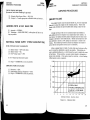
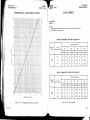
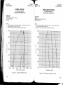
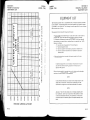
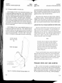
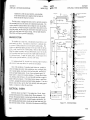
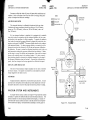
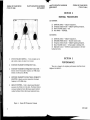
After an engine failure in flight, the best glide speed as shown in FigWhile gliding toure 3-1 should be established as quickly as possible.
ward a suitable landing area, an effort should be made to identify the cause
If time permits, an engine restart should be attempted as
of the failure.
If the engine cannot be restarted, a forced landing
shown in the checklist.
without power must be completed"
r 2,000
as soon as possible.
A , U T v I E T ESRH O W S D I S C H A R G E
SECTION 3
EMERGENCY PROCEDURES
F
l!
'.:;:::
10,000
I
( 1) A lt er nato r -- O F F .
(2) NonessentailElectrical Equipment -- OFF.
(3) Flight -- TERMINATE as soon as practical.
z
cc
a
8000
LU
F
uJ
6000
,r.'..,..:..:..:'
co
F
(9
tlt
-t-
4000
.,:.1.'
..r.'t.'.f'
:r'.'j"
2000
..::i:i.'
:.il':rli"
0
it"-l_
t
* SPEED
65 KIAS
I
* P R O P E L L EW
RI,N D T Y l I L L I NIG
.
{ <F r A P SU P * Z E R O W t N D
I
10
12
14
16
1B
G R O U N DD I S T A N C -EN A U T I C A LM I L E S
Figure 3-1.
Maximum Glide
3-9
SECTION 3
EMERGENCY PROCEDURES
CESS}IA
MODEL 1?2M
F O R C E DL A N D I N G 5
If all attempts to restart the engine fail and a forced landing is imminent, select a suitable fietd and prepare for the landing as discussed in
the checklist for engine off emergency landings.
Before attempting an "off airport" landing with engine power available, one should drag the landing area at a safe but low altitude to inspect
the terrain for obstructions and surface conditions, proceeding as discussed under the Precautionary Landing With Engine Power checklist.
Prepare for ditching by securing or jettisoning heavy objects located
in the baggage area and collect folded coats or cushions for protection of
occupantsr face at touchdown. Transmit Mayday message on 121- 5 MHz
Avoid a landing flare because of difficulty
giving location and intentions.
in judging height over a water surface.
L A N D I N G W I T H O U T E L E V A T O RC O N T R O T
Trim for horizontal flight(with an airspeed of approximately 60 KIAS
Then -do
and flaps set to 20") by using throttle and elevator trim control.
control the glide angle by
lqt "tt""g" ttt" "t"t
"t "ettl"g;
adjusting power exclusively.
At flareout the nose-down moment resulting from power reduction is
an adverse factor and the airplane may hit on the nose wheel. Consequently, at flareout, the elevator trim control should be adjusted toward
the full nose-up position and the power adjusted so that the airplane will
rotate to the horizontal attitude for touchdown. Close the throttle at touchdown.
FIRES
Although engine fires are extremely rare in flight, the steps of the
appropriate checklist should be followed i-f one is encountered. After
completion of this procedure, execute a forced landing.
The initial
ing insulation.
of the fire.
3- 10
indication of an electrical fire is usually the odor of burnThe checklist for this problem should result in elimination
crssNA
ifOpBt, LTZM
sEcTroN 3
EMERGENCY PROCEDURES
E M E R G E N C YO P E R A T I O N I N C L O U D S
re)
[ V " . u u m S Y s t e mF o i l u
In the event of a vacuum system failure during flight in marginal
weather, the directional indicator and attitude indicator will be disabled,
and the pilot will have to rely on the turn coordinator or the turn and bank
indicator if he inadvertently flies into clouds. The following instructions
turn coordinator or the turn
assume that only the electrieally-powered
and bank indicator is operative, and that the pilot is not completely proficient in instrument flYing.
EXECUTINGA I SOO TURN IN CTOUDS
Upon inadvertently entering the clouds, an immediate
made to turn back as follows:
plan should irc
(1) Note the time of the minute hand and observe the position of the
sweep second hand on the clock.
(2) When the sweep second hand indicates the nearest half-minute,
initiate a standard rate left turn, holding the turn coordinator sym*
bolic airplane wing opposite the lower left index mark for 60 seconds.
Then roll back to level flight by leveling the miniature airplane.
(3) check accuracy of the turn by observing the compass heading
which should be the reciprocal of the original heading.
(4) If necessary, adjust heading primarily with skidding motions
rather than rolling motions so that the compass will read more accurately.
(5) Maintain altitude and airspeed by cautious application of elevator
control.
Avoid overcontrolling by keeping the hands off the control
wheel and steering only with rudder.
E ' Y l E R G E N C YD E S C E N TT H R O U G H C t O U D S
U conditions preclude reestablishment of VFR flight by a 180' turn, a
descent through a cloud deck to vFR conditions may bl appropriate.
If.
possible, obtain radio clearance for an emergency descent through clouds.
To guard against a spiral dive, choose an easterly or westerly heading to
minimize compass card swings due to changing bank angles. In addition,
I(eep hands off the control wheel and steer a straight course with rudder
control by monitoring the turn coordinator.
Occaiionally check the compass heading and make minor corrections to hold an approximate
course.
Bef-ore descending into the clouds, set up a stabilized let-down condition
as follows:
(1) Apply tult rich mixture.
(2) Use full carburetor heat.
3 - 11
SECTION 3
EMERGENCY PROCEDURES
CESSNA
MOD E L 1?2M
(3) Reduce power to set up a 500 to 800 ft/min rate of descent.
(4) Adjust the elevator trim for a stabilized descent at 70-80 KIAS.
(5) Keep hands off the control wheel.
(6) Monitor turn coordinator and make corrections by rudder alone.
(7) Check trend of compass card movement and make cautious corrections with rudder to stop the turn.
(8) Upon breaking out of clouds, resume normal cruising flight"
R E C O V E R Y F R O A AA S P I R A L D I V E
SECTION 3
EMERGENCY PROCEDURES
ffJf# L'zNr
static source on, adjust indicated airspeed slightly
With the alternate
according to the arternate static source airspeed
,pprouch
*trins climb o"
configuration,
turt" in-section 5, appropriate to ventlwindow(s)
}iil'ili;n
speeds'
operating
the
normal
at
flown
be
to
ritpr"""
ZT::i;;'t*
altimeter variation from normal is 4 knots and
Maximum airspeed and
trre normal operating range with the window(s) closed. with
go r.;iJ",
larger viriations occur near stall speed' However, maxiwindow(s)open,
remains within 50 feet of normal.
mum altimeter variition
If a spiral is encountered, proceed as follows:
(1) CIose the throttle.
(2) Stop the turn by using coordinated aileron and rudder control to
align the symbolic airplane in the turn coordinator with the horizon
reference line.
(3) Cautiously apply elevator back pressure to slowly reduce the
airspeed to B0 KIAS.
(4) Adjust the elevator trim control to maintain an 80 KIAS glide.
(5) Keep hands off the control wheel, using rudder control to hold a
straight heading.
(6) Apply carburetor heat.
(7) Clear engine occasionally, but avoid using enough power to disturb the trimmed glide.
(B) Upon breaking out of clouds, resume normal cruising flight.
FLIGHT IN ICING CONDITIONS
Flight into icing conditions is prohibited.
An inadvertent encounter
with these conditions can best be handled using the checklist procedures.
The best procedure, of course, is to turn back or change altitude to escape icing conditions.
STATIC SOURCE BTOCKED
lf erroneous readings of the static source instruments (airspeed,
altimeter and rate-of-climb) are suspected, the alternate static source
valve should be pulled on, thereby supplying static pressure to these
instruments from the cabin.
NOTE
In an emergency on airplanes not equippedwith an alternate static source, cabin pressure can be supplied to the
static pressure instruments by breaking the glass in the
face of the rate-of-climb indicator.
3-t2
sPIN5
procedure
Shouldan inadvertent spin occur, the following recovery
used:
be
should
(1) RETARD THROTTLE TO IDLE POSITION.
(2) PTACE AILERONS IN NEUTRAL POSITION.
i S ) A P P LY AND HO LD FULL RUDDERO PPO SI TETO THE DI RECTION OF ROTATION.
THE RUDDERREACHESTHE STO P, M O VE THE
(4) JU S T ry
CONTROL-WEEET,BzuSKLY FORWARD FAR ENOUGH TO BREAK
THESTALL.Fu[ffivatormayberequiredataftcenterof
gravity loadings to assure optimum recoveries.
(5) HOL! THESE CONTROL INPUTS UNTIL ROTATION STOPS.
Prerililre relaxation of the control inputs may extend the recovery.
RUDDER, AND MAKE A
(6) AS ROTATION STOPS, NEUTRAT_tr,28
SMOOTHRECOVERY FROM THE RESULTINGDIVE.
NOTE
If disorientation precludes a visual determination of the
direction of rotation, the symbolic airplane in the turn
coordinator or the needle of the turn and bank indicator
may be referred to for this information.
For additional information on spins and spin recovery, see the
discussionunder SPINSin Normal Procedures (Section4).
R O U G H E N G I N E O P E R A T I O NO R L O 5 5 O F P O W E R
C A R B U R E T OIRC I N G
A gradual loss of RPM and eventual engine roughness may result from
3 -1 3
SECTION
3
EMERGENCY
PROCEDURES
r'Fecrr,.
MOD;;i;i]ft
the formation of carburetor ice. To clear the ice, apply full throtile and
pull the carburetor heat knob full out until the engine runs smoothly; then
remove carburetor heat and readjust the throttle. If conditions require
the continued use of carburetor heat in cruise flight, use the minimum
amount of heat necessary to prevent ice from forming and lean the mixture for smoothest engine operation.
S P A R KP L U G F O U L I N G
A slight engine roughness in flight may be causecl by one or more
spark plugs becoming fouled by carbon or lead deposits. This may be
verified by turning the ignition switch momentarily from BOTH to either
L or R position. An obvious power loss in single ignition operation is
evidence of spark plug or magneto trouble.
AJsuming that ipark plugs
are the more likely cause, lean the mixture to the recommenO"a lean setting for cruising flight.
If the problem does not clear up in several rninutes, determine if a richer mixture setting will prodrrce smoother operation. If not, proceed to the nearest airport for repairs using the BoTH
position of the ignition switch unless extreme roughness dictates the
trse
of a single ignition position.
I YA
l G N E T O I VA
l tFU NCTION
A sudden engine roughness or misfiring is usually evidence of magneto problems.
Switching from BOTH to either L or R ignition switch
position will identily which magneto is malfunctioning.
Sllect different
power settings and enrichen the mixture to determine if continued operation on BOTH magnetos is practicable.
If not, switch to the good mbgneio
and proceed to the nearest airport for repairs.
LOW OIL PRESSURE
If low oil pressure is accompanied by normal oil temperature, there
is a possibility the oil pressure gage or relief v-alve is maHunctioning,
A
leak in the line to the gage is not necessarily cause for an immediate precautiolary landing because an orifice in this line will prevent a sudden
loss of oil from the engine sump. However, a landing at the nearest airport would be advisable to inspect the source of trouble.
If a total loss of oil pressure is accompanied by a rise in oil temperature, there is good reason to suspect an engine failure is imminent.
Reduce engine power immediately and select a iuitable forced landine field.
Use only the minimum power required to reach the desired touchdSwn spoi.
3- 14
ffiilf LT*M
SECTION 3
EMERGENCY PROCEDURES
S U P P L YS Y S T E MM A L F UN C T I O NS
ELECTRICAL PO W E R
power supply system can be detected by
ilIalfunctions in ihe electrical
of the ammeter and over-voltage warning light; howo""iofrJ*onitoring
-^--no rhe cause of lhese malfunctions is usually diJficult to determine. A
drive belt or wiring is most likely the cause of alterna;;kil;ternato.r
although other factors could cause the problem. A damaged
ioiirir""es,
adjusted voltage regulator can also cause maffunctions.
oli-p"opeily
nature constitute an electrical emergency and should be
itris
ot
;"joiil;
Electrical power malfunctions usually fall into
immediately.
ir"ri-*itt,
rate of charge and insufficient rate of charge.
exceisive
;;;-;ri;tories:
the recommended remedy for each
describe
paragraphs
iollo*ing
iirl
situation.
E X C E S S I VR
EA T EO F C H A R G E
After engine starting and heavy electrical usage at low engine speeds
(such as extendedtaxiing) the battery condition will be low enoughto accept above normal charging during the initial part of a flight. However,
thirty minutes of cruising flight, the ammeter should be indicating
"tt""
Iess than two needle widths of charging current. If the charging rate were
to remain above this value on a long flight, the battery would overheat and
evaporatethe electrolyte at an excessive rate. Electronic components in
theblectrical system could be adversely affected by higher than normal
voltage if a faulty voltage regulator setting is causing the overchar$ng.
To pieclude these possibilities, an over-voltage sensor will automatically
shut down the alternator and the 6VdFVoltage warning light will illuminate
ETfif?!{fge voltage reaches approximately 16 volts. Assuming that the
malfunction was only momentary, an attempt should be made to reactivate
the alternator system. To do this, turn both sides of the master switch
off and then on again. If the problem no longer exists, normal alternator
charging will resume and the warning light will go off. If the light comes
on again, a malfunction is conJirmed. In this event, the flight should be
terminated and/or the current drain on the battery minimized because the
battery can supply the electrical system for only a limited period of time.
U-lhe emergency occurs at night, power must be conserved for later use
of Ianding lights and flaps during linding.
I N S U F F I C I E NRTA T EO F C H A R G E
If the ammeter indicates a continuous discharge rate in flight, the
alternator is not supplying power to the system and should be shut down
since the alternator field circuit may be placing an unnecessary load on
the system. AII nonessential equipment itroutO be turned off and the
flight terminated as soon as practical.
3-15/(3-16 blank)
SECTION 4
NORMAL PROCEDURES
4
SECTION
NORMALPROCEDURES
TABLEOF CONTENTS
Page
4-3
4-3
Introduction
Speeds For Safe OPeration.
CHECKLIST PROCEDURES
4- 5
4-5
4-5
4-5
4-5
4-5
4- 6
4- 6
4- 6
4- 6
4- 6
4-7
Preflight InsPection.
Cabin
Empennage
Right Wing, Trailing Eclge.
Right Wing.
Nose
Left Wing
Left Wing, Leading Edge
Left Wing, Trailing Edge
Before Starting Engine
Starting Engine
Before Takeoff
Takeoff
Normal Takeoff
Maximum Performance Takeoff
Enroute Climb .
Cruise
Descent
Before Landine.
Balked Landine.
Normal Landine
After Landing
Securing Airplane
AMPLIFIED
Starting Engine
+-l
4-7
4-7
4-B
4-B
4-B
4-B
4-9
4-9
4-9
4-9
PROCEDURES
4-11
4-1
SECTION 4
NORMAL PROCEDURES
{ A B L E O F C O N T E N T S( C o n t i n u e d )
Taxiing
Before Takeoff .
Warm-Up
Magneto Check .
Alternator Check .
Takeoff
Power Check
Wing FIap Settings
Crosswind Takeoffs
Enroute Climb .
Cruise
Stalls
Spins
Landing
Normal Landing
Short Field Landing
Crosswind Landing
Balked Landing
Cold Weather Operation
Starting
Flight Operations
Hot Weather Operation
Noise Abatement
L72M
SECTION 4
NORMAL PROCEDURES
INTRODUCTION
Page
4-11
4- 13
4- 13
4-13
4- 13
4 -1 3
4 -1 3
4-t4
4 -1 5
4 -1 5
4-15
4-17
4-t7
4 -1 9
4 -1 9
4 -1 9
4-20
4-20
4-20
4-20
4-22
4-23
4-23
Section 4 provides checklist and amplified procedures for the conduct
Normal procedures associated with Optional Sysof normal operation.
tems can be found in Section 9.
S P E E D SF O R S A F E O P E R A T I O N
Unless otherwise noted, the following speeds are based on a maximum weight of 2300 pounds and may be used for any lesser weight. However, to achieve the performance specified in Section 5 for takeoff distance, the speed appropriate to the particular weight must be used.
Takeoff, FlaPs UP:
Normal Climb Out
Maximum Performance Takeoff. Speed at 50 feet
Enroute Climb, Flaps Up:
NormaL, Sea Level
Normal, 10,000 Feet
Best Rate of Climb. Sea Level .
Best Rate of Climb, 10,000 Feet .
Best Angle of Climb, Sea Level
Best Angle of CIimLr, 10, 000 Feet
Landing Approach:
Normal Approacir, Flaps Up
Norrnal Approach, Flaps 40"
, 1n o
Short Field Approach, F.laps 'tv
Balked Landing:
During 'fransition to Maximum Power, Flaps 20o
Maximum RecommendedTurbulent Air penetration Speed:
2300 Lbs
1950Lbs
1600Lbs
Maximum DemonstratedCrosswind Velocity:
Takeoff or Landing .
70-80 KLAS
59 KLAS
80-90
70-80
?8
68
64
62
KIAS
KIAS
KIAS
KIAS
KIAS
KIAS
60.70 KIAS
55-65 KI,AS
60 KIAS
55 KIAS
97 KTAS
89 KTAS
80 KI,AS
15 KNOTS
4-3
CESSNA
MODEL 1?2M
SECTION4
NORMA L PROCEDURES
SECTION 4
NORIVIALPROCEDURES
itoost L72NI
C H E C K L I S TP R , O C E D U R E S
P R E F T I G H TI N S P E C T I O N
@ cABrN
- - REM O VE.
(1) Control Wheel Lock
o
F
F.
iz) Ignition !u1tc.tt - -
oN.
igl Master Switch
- - CHECK Q UANTI TY'
(4) FueI QuantitY I ndicat or s
oFF.
(5) Master Switch
child's seat is t o be
(6) BaggageDoor - - CHECK, lock wit h key if
occuPied.
@
e, v \ P E N N A G E
(1) R u d d e r G u s t L o c k - - R E M O V E '
(2) T a i l T i e - D o w n - - D I S C O N N E C T '
(3) C o n t r o l S u r f a c e s - - C H E C K f r e e d o m o f m o v e m e n t a n d s e c u r i t Y .
@
nIGHT wlNGTroilins Edge
(1) Aileron -- CHECK freeclom of movement and security.
@ n r G H Tw r N G
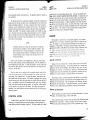
NOTE
Visually check airplane for general condition during
even
waLk-around inspection. In cold weather, r'emove
wing'
from
or
snow
ice
frost,
of
small accumulations
control
tail and control surfaces. AIso, make sure that
or deof
ice
accumulations
no
internal
surfaces contain
bris.Ifanightflightisplarured,checkoperationofall
lights, and make sure a flashlight is available'
Figure 4-1.
Preflight InsPection
(1) Wing Tie-Down -- DISCONNECT.
inflation.
izi Maii wheel Tire___ CHECK for proper
refueling, use sampler
each
after
and
day
the
of
(3) Before first itigtrt
cup and drain small"quantity of fuel from fuel tank sump quick-drain
valve to check for waier, sediment, and proper fuel grade (red).
(4) FueI Quantity -- CfinCX VISUALLY for desired level.
(5) FueI Fi l l er Cap - - SECI FE.
@ r.rose
(1) Engine OiI Level -- CHECK. P_qlqt_qpe-rate with less than six
. quarts. FilI to eight quarts for extended flight.
(2) Before first fiigtti of the day and after each refueling, prII out
strainer drain knob-for about four seconds to clear fuel strainer of
possible water and sediment. Check strainer drain closed. If water
is observed, the fuel system may contain additional water, and further drainlng of the system at the strainer, fueI tank sumps, and fuel
4-5
SECTION4
NORMAL PROCEDURES
selector valve drain plug will be necessary.
(3) Propeller and Spinner -- CHECK for nicks and security.
(4) Landing Light(s) -- CHECK for condition and cleanliness.
(5) Carburetor Air Filter -- CHECK for restrictions by dust or
other foreign matter.
(6) Nose Wheel Strut and Tire -- CHECK for proper inflation.
(7) Nose Tie-Down -- DISCONNECT.
(8) Flight Instrument Static Source Opening (left side of fuselage)
CHECK for stoppage.
@ I E F Tw r N G
(1) Main Wheel Tire -- CHECK for proper infiation.
(2) Before first flight of the day and a-fter each refueling, use sampler cup and drain small quantity of fuel from fuel tank sump quickdrainvalve to check for water, sediment ancl proper. fuel grade (red).
(3) Fuel Quantity -- CIIECK VISUALLY for desirecl level.
(4) FueI Filler Cap -- SECURE.
Q ) t E F Tw t N G L e o d i n s E d s e
(1) Pitot Tube Cover -- REMOVE and check opening for stoppage.
(2) Fuel Tank Vent Opening -- CHECK for stoppage.
(3) Stall Warning Opening -- CHECK for stoppage. To check the system, place a clean handkerchief over the vent opening and apply suction; a sound from the warning horn will confirm system operation.
(4) Wing Tie-Down -- DISCONNECT.
@
r E F Tw t N G T r o i l i n s E d s e
ff## L'tz*l
(2)
(3)
(4)
(5)
(6)
(7)
(8)
SECTION 4
NORIVIALPROCEDURES
-- COLD.
Carburetor Heat
-ON.
Master Switch
-p"i-"
-- AS REQUIRED (2 to 6 strokes; none if engine is warm).
itrrottle -- OPEN 1/8 INCH.
Propeller Area -- CLEAR.
Igniiion Switch -- START (release when engine starts).
Oi l P reszur e - - CHECK.
B E F O R ET A K E O F F
Cabin Doors and Window(s) -- CLOiSED and LOCKED.
Flight Controls -- FREE and CORRECT.
Elevator Trim -- TAKEOFF.
Flight Instruments -- SET.
Radios -- SET.
Autopilot (if installed) -- OFF.
Fuel Selector Val.ve -- BOTH.
Mixture -- zuCH (below 3000 feet).
(e) Parking Brake -- SET.
(10) T h r o t t l e - - 1 7 0 0 R P M .
Magnetos -- CHECK (RPM drop should not exceed 125 RPM
a.
on either magneto or 50 RPM differential between magnetos).
b.
Carburetor Heat -- CHECK (for RPM drop).
Engine Instruments and Ammeter -' CHECK.
c.
d.
Suction Gage -- CHECK.
( 1 1 ) Flashing Beacon, Navigation Lights and/or Strobe Lights -- ON
as required.
( 1 2 ) Throttle Friction Lock -- ADJUST.
( 1 3 ) Wing Flaps -- UP.
(1)
(2)
(3)
(4)
(5)
(6)
(?)
(8)
( 1 ) A i l e r o n - - C H E C K f o r f r e e d o m o f nlovement and securitv.
BEFORE STARTING ENGINE
(1)
(2)
(3)
(4)
( 5)
( 6)
Preflight Inspection -- COMPLETE.
Seats, Belts, ShoulderHarnesses -- ADJUST and LOCK.
FueI Selector Valve -- BOTH.
Radios, Autopilot, Electrical Equipment -- OFF.
B r ake s -- T ES T a n d S ET .
Cir c u i t B re a k e rs -- C H EC K IN .
STARTING ENGINE
(1) Mixture -- RICH.
4-6
TAKEOFF
NORftIAIIAKEOFF
(1) Wing Flaps -- up.
(2) Carburetor Heat -- COLD.
(3) Throtile -- FULL.
Elevator Control -- LrFT NOSEWHEEL (at 55 KrAS).
t:l
(D , C l i mb Speed- - ?0- 80 KI AS.
I I A X I ' I I U , V IP E RF OR , V I
A N C E T A K E OF F
(1) Wing Flaps -Up.
4-7
SECTION 4
NORMAL PROCEDURES
(2)
(3)
(4)
(5)
(6)
(?)
MOD
Carburetor Heat -- COLD.
Brakes -- APPLY.
Throttle -- FULL OPEN.
Brakes -- RELEASE.
Elevator Control -- SLIGHTLY TAIL LOW.
Climb Speed -- 59 KIAS (until aII obstacles are cleared).
if#'f nz'
-;A,S DESIRED'
(5) Wing FlaPs
-- 55-65 KIAS (flaps DOWN)'
AirJpeed
(6)
BATKED LAN DIN G
(1)
iZ\
(3t
(al
iSl
E N R O U T EC L I M B
( 1) A ir s p e e d -- ? 0 -9 0 KIA S.
SECTION 4
NORMAL PROCEDURES
Throttle -- FULL OPEN'
Carburetor Heat -- COLD'
Wing FIaPs -- 20" '
A i rsP eed - - 55 KI AS'
Wing FlaPs -- RETRACT slow1Y'
NOTE
If a maximum performance climb is necessa-ry, use
speeds shown in the Rate Of Climb chart in Section 5.
( 2) T h r o t t l e - - F U L L O P E N .
(3) Mixture -- FULL RICH (mi-xture may be leaned above 3000 feet).
NORMAL LANDING
( 1 ) Touchdown -- MAIN WHEELS FIRST.
(2) Landing Roll -- LOWER NOSE WHEEL GENTLY.
(3) Braking -- MINIMUM REQUIRED.
A F T E RT A N D I N G
CRUISE
( 1 ) Power -- 2200-2700RPM (no more than ?570).
( 2) E lev a to r T ri m -- A D J U S T "
(3) Mixture -- LEAN.
(1) Wing Flaps -- UP.
(2) Carburetor Heat -- COLD.
S E C U R I N GA I R P L A N E
DESCENT
( 1 ) Mixture -- RICH.
(2) P o w e r - - A S D E S I R E D .
(3) Carburetor Heat -- AS REQUIRED (to prevent carburetor icing).
(1)
(2)
(3)
(4)
(5)
(6)
Parking
Radios,
Mixture
Ignition
Master
Control
Brake -- SET.
Electrical Equipment, Autopilot -- OFF.
-- IDLE CUT-OFF (pulled full out).
Switch -- OFF.
Switch -- OFF.
Lock -- INSTALL.
B E F O R EL A N D I N G
(1)
(2)
(3)
(4)
4-B
Fuel Selector Valve -- BOTH.
Mixh-rre -- RICH.
Carburetor Heat -- ON (apply full heat before closing throttle).
Airspeed -- 60-70 KIAS (flaps UP).
4-9/(4-10 blank)
SECTION 4
NORMAL PROCEDURES
cESSrilA
MOD,EL ITZM
AMPLIFIED PROCEDURES
STARTING ENGINE
During engine starting, open the throttle approximately 1/B inch. In
warm temperatures, one or two strokes of the primer should be sufficient.
In cold weather, up to six strokes of the primer may be necessary. If the
engine is warm, no priming wiII be required. In extremely cold temperatures, it may be necessary to continue priming while cranking the engine.
Weak intermittent firing followed by puffs of black smoke from the'
exhaust stack indicate overprirning or flooding. Excess fuel can be
cleared from the combustion chambers by the following proceclure: Set
the mixture control full lean and the throttle fuIl open; then crank the engine through several revolutions with the starter.
Repeat the starting
procedure without any additional priming.
If the engine is underprimed (most likely in cold weather with a colcl
engine) it wiII not fire at all, and additional priming will be necessary.
As soon as the cylinders begin to fire, open the throttle slightly to keep it
running.
After starting, if the oil gage does not begin to show pressure within
30 seconds in the summertime and about twice that long in very cold
weather, stop engine and investigate.
Lack of oil pressure can cause
serious engine damage. After starting, avoid the use of carburetor heat
unless icing conditions prevail.
NOTE
Additional details concerning cold weather starting ancl
operation may be found under COLD WEATHER OPERATION paragraphs in this section.
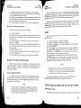
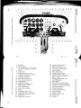
T A X I I NG
When taxiing, it is important that speed and use of brakes be held to
a minimum and that all controls be utilized (see Taxiing Diagram, figure
4-2) to maintain directional control ancl balance.
The carburetor heat control knob should be pushed full in during all
ground operations unless heat is absolutely necessary. When the lmob is
4-1,1
SECTION 4
NORMAL PROCEDURES
CESSNA
MODEL L72I[/,I
prlled out to the heat position,
SECTION 4
NORIVIAL PROCEDURES
air entering the engine is not filtered.
Taxiing over loose gravel or cinders should be done at low engine
speed to avoid abrasion and stone damage to the propeller tips.
B E F O R ET A K E O F F
USE UP AILERON
ON LH WING AND
NEUTRAL ELEVATOR
USE UP AILERON
ON RH WING AND
NEUTRAL ELEVATOR
WARIIA-UP
If the engine accelerates smoothly, the airplane is ready for takeoff.
Since the engine is closely cowled for efficient in-flight engine cooling,
precautions should be taken to avoid overheating during prolonged engine
operation on the ground. Also, Iong periods of idling may cause fouted
spark plugs.
t-Il
USE DOWN AILERON
ON LH WING AND
DOWN ELEVATOR
USE DOWN AILERON
ON RH WING AND
DOWN ELEVATOR
IUAGNETO CHECK
The magneto check should be made at 1700 RpM as follows. Move
ignition switch first to R position and note RPM. Next move switch back
to BOTH to clear the other set of plugs. Then move switch to the L position, note RPM and reburn the switch to the BorH position. RpM drop
should not exceed 125 RPM on either magneto or show greater than b0
RPM differential between magnetos. If there is a doubt concerning operation of the ignition system, RPM checks at higher engine speeds will usually confirm whether a deficiency exists.
An absence of RPM drop may be an indication of faulty grounding of
one side of the ignition system or should be cause for suspicion that the
magneto timing is set in advance of the setting specified.
A T T E R N A T O RC H E C K
CODE
NOTE
wrND DTRECTToN
quartering tail winds require caution.
!tro.n_S
Avoid sudden bursts of the throfile and sharp
braking when the airplane is in this attitude.
Use the steerable nose wheel and rudder to
maintain direction.
)
Prior to flights where verification of proper alternator and voltage
regulator operation is essential (such as night or instrument fiights), a
positive verification can be made by loading the electrical system
momentarilv (3 to b seconds) with the optional hnling light (if so ;A;ipp;;i,
;;
by operating the wing flaps during the engin" *""p
(l?00 RpM).' The ammeter will remain within a neeclle width of zero if the alternator and voltage regulator are operating properly.
TAKEOFF
POWERCHECK
Figure 4-2.
Taxiing Diagram
It is important to check full-throttle engine operation early in the
4-12
4-r3
SECTION 4
NORMAL PROCEDURES
SECTION 4
NORMAL PROCEDURES
CESSNa
MODEL1?2il
takeoff run. Any sign of rough engine operation or sluggish engine acceleration is good cause for discontinuing the takeoff. If this occurs, you
&re
-"
justified in making a thorough full-throttle,
static runup before another
takeoJf is_attempted.
The engine should run smoothly and turn approximately 2300 to 2420 RPM with carburetor heat off and mixture full rich.
NOTE
Carburetor heat should not be used during takeoff unless
it is absolutely necessary for obtaining smooth engine
acceleration.
Full-throttle runups over loose gravel are especiatly harmful to propeller tips. When takeoffs must be made over a gravel. surface, it is very
important that the throttle be advanced slowly. This allows the airplane
to start rolling before high RPM is cleveloped, ancl the gravel will be l;lown
back of the propeller rather than pulled into it. When unavoidable snrrtll
dents appear in the propeller blades, they should be inrnecliately corrccteclas described in Section B under Propeller Care.
IAKEOFFS
CROSSWIND
Takeoffs into strong crosswinds normally are performed with the min:ff,rm flap setting necessary for the field length to minimize the drift anli"-i---,iOiately after takeoff. The airplane is accelerated to a speed
?itntfy higher than normal, then pulled off abruptly to prevent possible
while drifting. When clear of the ground,
J"itfing back to the runway
-r*U"
i coordinated turn into the wind to correct for drift.
E N R O U T EC L IM B
Normal climbs are performed with flaps up and fuIl throttle and at
spedd$-5to 10 knots higher than best rate-of-climb speedsfor the best
-Cffiination of performance, visibility and engine cooling. The mixture
shouldbe full rich belorv 3000 feet and may be leaned above 3000 feet for
smoother operation or to obtain maximum RPM. If an obstruction dictates
the use of a steep climb angle, the best angle-of-climb speed should be
used with flaps up and maxinrum power.
NOTE
Prior to takeoff from fields above 3000 feet elevation, the mixtur+r
should be leaned to give maximum RPM in a full-throttle,
static rumrit.
After full throttle is applied, acljust the throttle friction lock cloc,,.wise to prevent the throttle from creeping back from a maximurn pDWr'rposition. Similar friction lock adjustments should be made as reouirr,-l
in other flight conditions to maintain a fixed throttle settinc."
WING
FLAP SETTINGS
Normal and obstacle clearance takeoffs are performecl with wing ilaps
up. The use of 1.0' flaps wiII shorten the ground run approximately L0 , .
but this advantage is lost in the climb to a 50-foot obstacle. Therefore.
the use of 10" fla"ps is reserved fgr mininrum ground runs or for takeolf
fiom soft or rough fields-. If 10o of flaps are used for minimurn grouncl
runs,-it is preferable to leave them extended rather than retract them in
the climb to the obstacle. In this case use an obstacle clearance speed of
55 KIAS. As soon as the obstacle is cleared, the flaps may be retiacted
as the aircra-tt accelerates to the normal flaps-up climb-out speed.
During a high altitude takeoff in hot weather where climb would be
marginal with 10' flaps, it is recommended that the flaps not be used for
takeoff. Flap settings greater than 10" are not approved for takeoff.
4-L4
Climbs at speecls lower than the best rate-of-climb speed
should be of short duration to improve engine cooLing.
CRUISE
Normal cruising is performed between 55%and 75%power. The engine
RPM;;a-6b-iiespondingluel consumption for various altitudes can be determined by using your Cessna Power Computer or the data in Section 5.
NCTIE
Cruising should be done at 65Voto 75% power until a total
-bT
50'hours has accumulated or oil consumption has staSIIiZdii. This is to ensure proper seating of the rings and
TJ*apliiicable to new enginei, anclengines in service folJg$Ltugcylinder replacement or top overhaul of one or
. mgr"e cylinders.
The Cruise Performance Table, Figure 4-3, illustrates the true airspeedand nautical miles per gallon during cruise for various altitudes and
Percent power. This table should be used as a guide, along with the avail4 - 15
,"""Tii|,il
SECTION 4
NORMAL PROCEDURES
7 5 %P O W E R
6 5 %P O W E R
5 5 %P O W E R
ALTITUDE
KTAS
NMPG
KTAS
NMPG
KTAS
NMPG
SeaLevel
112
13.5
106
14.7
97
15.2
4000 Feet
116
14.O
109
15 . ' l
99
15.5
8000 Feet
120
14.5
112
15.6
102
S t a n d a r dC o n d i t i o n s
Figure 4-3.
16 0
Zero Wind
Cruise Performance Tabie
able winds aloft information, to determine the most favorable altitucte and
power setting for a given trip. The selection of cruise altitude on the
basis of the most favorable wind conditions and the use of low power settings are significant factors that should be considered on every trip to
reduce fuel consumption.
To achieve the recommended lean mixture fuel consumption figures
shown in section 5, the mixture shouid be leaned as foilows:
(1) Pull the mixture control out until engine RPM peaks and begils
to fall off.
(2) Enrichen slightly back to peak RpM.
For best fuel economy at ?51} power or less, operate at the leanest
mixfure that rezults in smooth engine operation or at 50 RPM on the lean
side of the peak RPM, whichever occurs first.
This wilI result in approximately 5Ybgreater range than shown in this handbook.
carburetor ice, as evidenced by an unexplainecr drop in RpM, can be
removed by application of full carburetor heat. Upon regaining the original RPM (wittr heat off), use the minimum amount of heat (by trial ancl
error) to prevent ice from forming.
Since the heated air causes a richer
mixfure, readjust the mixture setting when carburetor heat is to be used
continuously in cruise flight.
The use of full carburetor heat is recommended during flight in heavy
rain to avoid the possibility of engine stoppage due to excessive water ingestion or carburetor ice. The mixbure setting should be readjusted for
smoothest operation.
In extremely
4-16
heavy rain,
the use of partial
carhrretor
heat (control
ffiL,zM
SECTION 4
NORIVIALPROCEDURES
*x?qd:**,:J*qi'i#"fi"
ffifi;;fr?ljj#ffi
operation'
STALLS
T h e s t a l l c h a r a c t e r i s t i c s a r e c o n v e n t i o n a ] a n d a u r a l w a r n 10
i n glarots
i s p r o -above
warning horn which sounds between 5 and
viaei'UV u "t^ff
ine statt in all configurations'
weight for both forward
Power-off stalt speeds at maximum
5'
Section
in
presented
c. g. positions are
and a-ft
S P I NS
within certain restrictIntentional spins are approved in this airplane
rear seat(s) are not
occupied
or
loadings
baggage
with
ed loadings. Spins
approved.
items should be
However, before attempting to perform spins several
be atshould
spins
No
flight.
a
sa^fe
assure
to
be carefuIly consiclered
both in spin entries
tempted wiitrout first having received clual inslr*ction
''rho is familiar with the
and spin recoveries from Jqualified instructor
spin characteristics of the Cessna 172M.
The cabin shoulcl be clean anci all loose equipment (including the miFor a solo
crophone and rear seat belts) should be stowed or secured.
flig-ht in which spins will be conducted, the copilot's seat belt and shoulder
harness should also be secured. The seat belts and shoulder harnesses
should be actjusted to provide proper restraint during all anticipated fligltt
conditions. However, care should be taken to ensure that the pilot can
easily reach the flighl controls and produce maximum control travels.
It is recommended that, where feasible, entries be accomplished at
high enough altitude that recoveries are completed 4000 feet or more above
ground level. At least 1000 feet of altitude loss should be allowed for a
1- turn spin and recovery, while a 6- turn spin and recovery may require
somewhat more than twice that amount. For example, the recommended
entry altitude for a G- turn spin would be 6000 f eet above ground level. In
any case, entries should be planned so that recoveries are completed weII
-abovethe minimum 1b00 feet above ground level required by FAR 91.71.
Another reason for using high altitndu" for practicing spins is that a
4-r7
SECTION 4
NORMAL PROCEDURES
*o"9ttifl*il
greater field of view is provided which will assist in maintaining
orientation.
SECTION 4
NORi\4AL PROCEDURES
L l72M
coordinator or the needle of the turn and bank indicator
may be referred to for this information.
pilot
The normal entry is made from a power-off stall. As the
stall i.s *o'
oproached, the elevator control should be smoothty pulled
to the ruli uit
position.
Just prior to reaching the stall 'breaki,
rudder control in the
desired direction of the spin rotation should be applied so that
fulI
deflection is reached almost simultaneously with-ieaching fuII
"uoo!.
un_ul.iito'..
A slightly greater rate of deceleration than for normal
stall entnes, application of ailerons in the direction of the desired spin,
and the use of
power at the entry will assure more consistent and positive
entries to irre
spin. As the airplane begins to spin, reduce the power to idle ano
return
the ailerons to neutral. Both elevator and rudder controls
shoulcl be held
full with the spin until the spin recovery is initiated. An inadvertent
relaxation of either of these controls could result in the development of
a nosedown spiral.
Variation in basic airplane rigging or in weight and balance due to
installed equipment or right seat occuparcy can cause differences in bein extended spins. These differences are normal and
iiuio", particularly
in the spin characteristics
and in the spiraling
variations
in
result
wi1
tendencies for spins of more than 2 turns. However, the recovery technique
should always be used and will result in the most expeditious recovery from
anY sPin,
For the purpose of training in spins and spin recoveries,
.
a 1 or 2
turn spin is adequate and should be used. up io 2
turns, tire spin wiil progress to a fairly rapid rate of rotation and aiteep attibude. gpplicat.ion
o1
^turn)"
recovery controls will produce prompt recoveries (witfrin l/4
ou.ing extended spins of two to three turns or more, the spin will tencl
to
change into a spiral, particularly to the right. This witl be
accompsniecl
by an increase in airspeecl and gravity loads on the airplane.
If this 1ccurs' recovery should be accomplished quickly by leveling the
wings urd
recovering from the resulting dive.
TANDING
Intentional spins with flaps extended are prohibited,
speeds which may occur during recovery are potentially
flap/vnng structure.
N O R ' Y l A LL A N D I N G
NormaL landing approaches can be made with power-on or power-off
with any flap setting desired. Surface winds and air turbulence are usually the primary factors in determining the most comfortable approach
speeds. Steep slips should be avoidecl with flap settings g"eater than 20'
due to a slight tendency for the eLevator to oscillate unaer certain combinations of airspeed, sicleslip angle, and center of gravity loadings.
Regardless of how many turns the spin is held or
how it is enterecl,
the following recovery technique should be
used:
(1) VERIFY THAT THROTTLE IS IN IDLE
PoSITIoN AND AILERoNs
ARE NEIITRAL.
(2) APPLY AND HOLD FULL RUDDER
OPPOSITE TO THE DIRECTION OF ROTATIOTI(3) JUST AqTER THE RUDDER REACHES
THE STOP, MOVE THE
CONTROT,_WTTEE-I, BRISKLY FORWARD FAR ENOUGH
TO BREAK
THE STALL.
(4) 4O!P THESE CONTROL INPUTS
UNTIL RCIATION STOPS.
(5) ffi-oTaTToI-lT9PS,
NEUTRA LIZE RUDDER, AND MAKE A
SMOOTHRECOVERY FROM THE RESULTINGDIVE.
NOTE
carburetor heat should be applied prior
reduction or closing of the throttle.
If disorientation precludes a visual determination of the
direction of rotation, the symbolic airplane in the turn
4-18
to any significant
. Actual touchdown shourd be made with power-off and on the main
wheels first to reduce the
landing speed and subsequent need for braking
landing roll.
The nose wheel is lowered to the runway genily after
lljn"
tne
speed has diminished to avoicl unnecessary
nose gear loads. This
procedure is
especially important in rough or soft field landings.
S H O R IF I E T DL A N D I N G
maximum performance short field landing in smooth air condi-
,tri*f**frtu{,iHri*s'g
t,^'Jol^1
NO{TE
since the high
damaging to the
4-t9
SECTION 4
NORMAL PROCEDURES
SECTION 4
NORI\4AL PROCEDURES
CESSNA
MOD E L 1?2M
tain the approach speed by lowering the nose of the airplane.
Tarchdolryn
should be made with power off and on the main wheels first.
Immediately
a-fter touchdown, Iower the nose wheel and apply heavy braking &s r€eli1pa
For maximum brake effectiveness, retract the flaps, hold the controi
wheel fulI back, and apply maximum brake pressure without stiding the
tires.
CR,OSSWIND TANDING
when landing in a strong crosswind, use the minimum flap setting
required for the field length. If flap settings greater than 20" are used
in sideslips with full rudder deflection, some elevator oscillation may be
felt at normal approach speeds. However, this cloes not affect control of
the airplane. Although the crab or combination method of drift correction
may be used, the wing-low methocl gives the best control. After touchdown, hold a straight course with the steerable nose wheel and occasional
braking if necessary.
The maximum allowable crosswind velocity is dependent upon pilot
capability as well as aircraft limitations.
With average pilot technique.
direct crosswinds of 15 knots can be handled with sa-fetv.
BATKED TANDING
In a balked landing (go-around) climb, reduce the wing flap settilg to
20" immediately after full power is appliecl. If the flaps *"""
extenclecj to
40"' the reduction to 20o may be approximated by placing the flap switch
in the UP position for two seconds ancl then refurning the switch to neutyal.
If obstacles must be cleared during the go-arounci climb, Ieave the wing.
flaps in the 10o to 20o rang'e and maintain a sa^feairspeed until the obstacles are cleared. Above 3000 feet, lean the mixfure to obtain maximurn
RPM. After clearing any obstacles, the flaps may be retracted as the airplane accelerates to the normal flaps-up climb speed.
COLD WEATHER OPERATION
STARIING
Prior to starting on a cold morning, it is advisable to pull the propelIer through several times by hand to "break loose" or "limber" the oil,
thus conserving battery energy.
4-20
NOTE
When pulling the propeller through by hand, treat it as
or broken
if the ignition switch is furned on' A loose
to
ground wire on either magneto could cause the engine
fire.
an external pre16 a{tremelv cold (-18"C anct lower) weather, the use of
possible
whenever
recommended
are
power
source
ff;;;;;
""ternal
and to reduce wear and abuse to the engine and
starting
i"1;;;'p""itiu"
Pre-heat will thaw the oil trapped in the oil cooler'
electrical system.
be congealed prior to starting in extremely cold temwill
;;t.n n""na6ty
lvtt"n using an external power source' the posltion.of the mas;;;;t";"r.
Ref91 to section T under Ground service PIug
importan[.
is
i;;;;it"h
details'
neceptacle for operating
ColdweatherstartingproceduresareaSfollows:
Wjth Prehe4
(1) With ignition switch OFF and throttle closed, prime the engine
hand'
four to eight strokes as the propeller is being turned over by
NOTE
Use heavy strokes of primer for best atomization of fuel.
Afterpriming,pushprimerallthewayinandturnto
locked position to avoid possibility of engine drawing fuel
through the Primer.
(2)
(3)
(4)
(5)
(6)
(?)
(8)
Propeller Area -- CLEAR.
Master Switch -- ON.
Mixhrre -- FULL RICH.
Throttle -- OPEN 1/8 INCH.
Ignition Switch -- START.
Release ignition switch to BOTH when engine starts.
Oil Pressure -- CHECK.
Without Preheat:
(1) Prime the engine six to ten strokes while the propeller is being
turned by hand with throttle closecl. Leave primer charged and ready
for stroke.
(2) Propeller Area -- CLEAR.
(3) Master Switch -- ON.
(4) Mixhrre -- FULL RICH.
4-21
CESSNA
MODEL 1?2M
SECTION 4
NORMAL PROCEDURES
(5) Ignition Switch -- START.
(6) Pump throttle rapidly to fuII open twice. Return to 1/8 inch
open position.
(7) Release ignition switch to BOTH when engine starts.
(B) Continue to prime engine until it is running smoothly, or alternately pump throttle rapidly over first 1/4 ot total travel.
(9) OiI Pressure -- CHECK.
(10) Pull carburetor heat knob full on after engine has started.
Leave on until engine is running smoothly.
(11) Lock Primer.
NOTE
If the engine does not start during the first few attempts,
or if the engine firing diminishes in strength, it is probable that the spa.rk plugs have been frosted over. Preheat must be used before another start is atternpted.
iAurioNl
pumping the throttr"
fuel to accumulate
;;;w
in the intake air duct, creating a fire hazard in the event
of a backfire.
If this occurs, maintain a cranking action
to suck flames into the engine. An outside attendant with
a fire extinguisher is advised for cold starts without preheat.
During cold weather operations, no indication will be apparent on the
oil temperature gage prior to takeoff if outside air temperatures are yery
cold. After a suitable warm-up period (2 to 5 minutes at 1000 RpM) , tccelerate the engine several times to higher engine RPM. If the engine accelerates smoothly and the oil pressure remains normal and steady, the
airplane is ready for takeoff.
FLIGHT OPERATIONS
Takeoff is made normally with carburetor
leaning in cruise.
heat off.
SECTION4
NORMAL PROCEDURES
CESSNA
MODEL I72M
H O T W E A T H E RO P E R A T I O N
Refer to the general warm temperature starting information under
Starting Engine in this section. Avoid prolonged engine operation on the
ground.
N O I S EA B A T E M E N T
Increased emphasis on improving the quality of our environment requires renewed effort on the part of all pilots to minimize the effect of
aircra^ft noise on the Public.
We, as pilots, can demonstrate our concern for environmental improvement, by application of the following suggested procedures, and
thereby tend to build public support for aviation:
(1) Pilots operating aircra-ft under VFR over outdoor assemblies of
persons, recreational and park areas, and other noise-sensitive
areas should make every effort to fly not less than 2,000 feet above
the surface, weather permitting, even though flight at a lower leveI
may be consistent with the provisions of government regulations.
(2) During departure from or approach to an airport, climb aufter
takeoff and descent for landing should be made so as to avoid prolonged flight at low altitude near noise-sensitive areas.
NOTE
The above recommended procedures do not apply where
they would conflict with Air Tra-tfic Control clearances
or instructions, or where, in the pilotts judgement, an
altitude of less than 2,000 feet is necessary for him to
adequately exercise his duty to see and avoid other aircraf t.
Avoid excessive
Carburetor heat may be used to overcome any occasional engine
roughness due to ice.
When operating in temperatures below -18oC, avoid using partial carburetor heat. Partial heat may increase the carburetor air temperature
to the 0'to 2I'C range, where icing is critical under certain atmospheric
conditions.
4-22
4- 2s/ ( 4- 24 blank)
SECTION b
PERFORMANCE
SECTION5
PERFORMANCE
,1,'
lrI
ill
il'
il
il
l',
I
I
TABLE OF CONTENTS
Page
Introduction
Use of Performance Charts
SampleProblem
Takeoff
Cruise
Fuel Required
Landing
Figure 5- 1, Airspeed Calibration - Normal Static Source
Airspeed Calibration - Alternate Static Source
Figure 5-2, Temperature Conversion Chart .
Figure 5-3, Stall Speeds
Figure 5-4, Takeoff Distance - 2300 Lbs
Takeoff Distance - 2100 Lbs and 1900 Lbs
Rate of Climb
Time, Fuel, and Distance to Climb
Cruise Performance .
Range profile - 38.0 Gallons Fuel
Range Profile - 48. 0 Gallons Fuel
Figure 5-9, Endurance profile - 3 { } . 0 G a l l o n s
Endurance Profile - 4 8 . 0 G a l l o n s
Figure 5-10, Landing Distance
Figure
Figure
Figure
Figure
5- 5,
5-6,
5-7,
5-8,
.
5-3
5-3
5-3
5- 4
5-5
5-6
5-7
5-8
5-9
5 -1 0
5-11
5-t2
5 -1 3
5- L4
5-15
5 -1 6
5-17
5 -1 8
5-19
5-20
5-21
5-r/(5-2 blank)
SECTION 5
PERFORMANCE
| N T R o DU C T I ON
performance data charts on the following pages are presented so that
g,6s'n&y know what to expect from the airplane under various conditions,
Lid ul"o, to facilitate the planning of flights in detail and with reasonable
The data in the charts has been computed from actual flight
i""uru"y.
airplane and engine in good condition and using average
the
with
lests
piloting techniques'
It should be noted that the performance information presented in the
finge and endurance profile charts allows for 45 minutes reserve fuel
based on 45% power. Fuel flow data for cruise is based on the recommended lean mixture setting. Some indeterminate variables such as mi:
propelk,r'
fuel
metering
characteristics,
technique,
engine
and
leaning
fure
condition, and air turbulence may account for variations of 70% or more
in range and endurance. Therefore, it is important to utilize all available
information to estimate the fuel required for the particular flight.
U S E O F P E R F O R M A N C EC H A R T S
Performance data is presented in tabular or graphical form to illustrate the effect of different variables.
Sufficiently detailed inforrnalion is
provided in the tables so that conservative values can be selected and used
to determine the particular performance fig;ure with reasonable accuracy.
SAMPLE PROBLEM
The following sample flight problem utilizes information from the
various charts to determine the preclictecl performance data for:r typical
flight. The following information is known:
AIRPI,A NE CONFIG URATION
Takeoff weight
Usable fuel
2250 Pounds
38 Gallons
TAKEOFF CONDITIONS
Field pressure altitude
Temperature
Wind component along runway
Field length
1500 Feet
28"C (16"C above standard)
12 Knot Headwind
3500 Feet
5-3
SECTION 5
PERFORMANCE
SECTION 5
PERFORMANCE
ff#i'f nz'
CRUISE CONDITIONS
Total distance
Pressure altitude
Temperature
Expected wind enroute
420 Nautical Miles
5500 Feet
20"C (16"C above standard)
10 Knot Headwind
LANDING CONDITIONS
Field pressure altibude
Temperature
Wind component along runway
Field leneth
2000 Feet
25" C
6 Knot Headwind
3000 Feet
TAKEOFF
The takeoff distance chart, figure 5-4, should be consulted, keeping
in mind that the distances shown are based on maximum performance
techniques. Conservative distances ca.n be estabiished by reading the
For
chart at the next higher value of weight, altitude and temperature.
exanrple, in this particular sample problem, the takeoff distance information presented for a weight of 2300 lbs. , a pressure altitude of 2000 feet
and a temperature of 30oC should be used and results in the following:
Ground roll
Total distance to clear a S0-foot obstacle
1 1 5 5F e e t
2030 Feet
A correction for the effect of wind may be made based on Note 3 of the
takeoff chart. The distance correction for a 12 knot headwind is:
12
-T
Knots
KnoiF
'x
problem.
the sarnple
C R UI 5 E
The cruising altitude and winds aloft information have been given for
this flight. However, the power setting selection for cruise must be determined based on several considerations. These include the cruise performance characteristics of the airplane presented in figure 5-7,..the
range profile chart presented in figure 5-8, and the endurance profile
chart presented in figure 5-9.
The range profile chart illustrates the relationship between power
and range. Considerable fuel savings and longer range result when lower
power settings are used.
For this sample problem with a cruise altitude of 5500 feet and distance of. 420 nautical miles, the range profile chart indicates that use of
a7\Vo power setting will necessitate a fuel stop, in view of the anticipated
10 knot headwind component. However, selecting a 65(h power setting
from the range profile chart yields a predicted range oI 477 nautical miles
under zero wind conditions. The endurance profile chart, figure 5-9,
shows a corresponding 4.4 hours.
The range figure of 417 nautical miles is corrected to account for the
expected 10 knot headwind at 5500 feet.
Range, zero wind
Decrease in range due to wind
(4.4 hours x 10 knot headwind)
Corrected range
loTo = rBToDecrease
477
44
TJ-5Nautical Miies
This results in the following distances, corrected for wind:
Ground roll, zero wind
Decrease in ground ro11
( 1 1 5 5t e e t x r S % )
Corrected ground roll
Total distance to clear a
50-foot obstacle, zero wind
Decrease in total distance
(2030 feet x 137o)
Corrected total distance
to clear 50-foot obstacle
1155
150
ft'OilPeet
2030
2.64
1 7 6 6F e e t
These distances are well within the takeoff field length quoted earlier f or
5-4
This indicates that the trip can be made without a fuel stop using approximately 6b7opower.
The cruise performance chart, figure 5-7, is entered at 6000 feet
altitude and 20oC above standard temperature.
These values most nearly
correspond to the expected altibude and temperature conditions. The engine speed chosen is 2500 RPM, which results in the following:
Power
True airspeed
Cruise fuel flow
627o
109 Knots
7.0 GPH
The power computer may be used to determine power and fuel consumption
during the flighi.
5-5
SECTION 5
PERFORMANCE
CESSNe
MODEL 1?2M
FUEL REQUIRED
:
CESSNA
raoppl, 172ltyn
SECTION 5
PERFORMANCE
for cruise is enduralce times fuel consum$ion:
The fuel required
The total fuel requirement for the flight may be estimated using the
performance information in figures 5-6 and 5-7, For this sample problem, figure 5-6 shows that a climb from 1000 feet to 6000 feet requires
2.0 gallons of fuel and may be used as a conservative estimate for this
problem.
This is for a standard temperature (as shown on the climb
chart).
The approximate effect of a non-standard temperature is to increase the time, fuel, and distance by L\Vo f.or each 10"C above standard
temperature, due to the lower rate of climb.
In this case, assuming a
temperature 16"C above standard, the correction would be:
4. t hours x ?. 0 gallons/hour
The total estimated fuel required
= 28. 7 Gallons
is as follows:
Engine start, taxi, and takeoff
Climb
Cruise
Total fuel required
This will leave a fuel reserve
1. 1
2.3
28.7
Tt
Gallons
of :
16:C x loTo = 760/o
Increase
Tre^
38.0
-32.1
With this factor included, the fuel estimate would be calculated as follows:
Fuel to climb, standard temperature
Increase due to non-standard temperature
(2.0 x 1670)
Corrected fuel to climb
2.0
0. 3
ZT Gallons
5. 9 Gallons
Once the flight is underway, ground speed checks will provide a more
accurate basis for estimating the time enroute and the corresponding fuel
required to complete the trip with ample reserve.
LANDING
In addition, the distance to climb, as given in figure 5-6, may be corrected for non-standard temperature as follows:
Distance to climb, standard temperature
Increase dr.reto non-standard temperature
(14 nautical miles x 7670)
Corrected distance to climb
74
2
fE wautical Miles
The resultant cruise distance is:
Total distance
Climb distance
Cruise distance
Ground roll
Total distance to clear a 50-foot obstacle
420
-16
ft'?[ Nautical Miles
with an expected10 knot headwind, the ground speeclfor cruise is predic t ed t o be:
109
-10
E Knots
Therefore, the time required for the cruise portion of the trip is:
404 Nautical Miles
-F
Knots
A proceclure similar to the takeoff calculations should be used for
Figure 5-10
estimating the landing distance at the destination airport.
presents maximum performance technique landing distances for various
airport altitude and temperature combinations. The distances corresponding to 2000 feet altitude and 30"C should be used and result in the
following:
= 4.1 Hours
590 Feet
1370 Feet
A correction for wind may be made based on Note 2 of the landing chart.
The distance correction for a 6 lanot headwind is:
6 Knots
ffi
x
lo%o= 77oDecrease
This results in the following wind-corrected
figures:
Ground roll
Total distance over a 50-foot obstacle
549 Feet
1274 Feet
These distances are well within the landing field length quoted previously
for this sample problem.
5-1
SECTION 5
PERFORMANCE
cESSNA
MOD E L 1?2M
SECTION 5
PERFORMANCE
CESSNA
MoDEL 772M
A I R S P E E DC A T I B R A T I O N
A I R S P E E DC A L I B R A T I O N
N O R ' Y l A tS I A I I C S O U R C E
A I T E R N A T ES I A T I C S O UR C E
HEATER/ VENTS
ANDWI NDO WS
CLO SED
F L A P SU P
N O R M A LK I A S
A L T E R N A T EK I A S
40
49
50
55
60
62
70
70
B0
B0
90
89
100
99
11 0
108
120
118
F L A P S1 O O
KIAS
KCAS
50
51
60
61
70
71
B0
82
90
91
40
40
50
51
60
61
70
71
B0
81
85
85
40
38
50
50
60
60
70
10
B0
79
85
83
100
101
1 1 0 120
1 1 ' l 121
130
131
140
141
FmPs too
F L A P SU P
KIAS
KCAS
40
39
40
49
50
55
60
62
70
71
B0
B0
85
85
130
128
140
138
N O R M A LK I A S
KIAS
ALTERNATE
FLAPS4OO
N O R M A LK I A S
KIAS
ALTERNATE
T I E A T E R / V E N TOSP E NA N D W I N D O W C
SLOSED
F L A P S4 O O
F L A P SU P
KIAS
KCAS
40
4t
50
54
Figure 5-1.
60
62
70
71
B0
81
85
86
Airspeed Calibration (Sheet 1 of 2)
N O R M A LK I A S
KIAS
ALTERNATE
40
36
50
48
60
59
10
70
B0
B0
90
89
40
38
50
49
60
59
10
69
80
79
85
84
40
34
50
47
60
57
70
67
80
77
85
81
100
99
110
iOB
120
11 8
130
128
140
139
100
103
11 0
113
120
123
130
133
i40
143
F L A P S1 O O
N O R M A LK I A S
ALTERNATEKIAS
FLAPS4OO
N O R M A LK I A S
ALTERNATEKIAS
WINDOWO
S PEN
F L A P SU P
N O R M A LK I A S
ALTERNATE
KIAS
40
26
50
43
60
51
70
10
B0
82
90
93
40
25
50
43
60
57
70
69
B0
B0
85
85
40
25
50
41
60
54
70
67
B0
tB
85
84
F L A P S1 O O
N O R M A LK I A S
ALTERNATE
KIAS
FLAPS4OO
N O R M A LK I A S
ALTERNATE
KIAS
Fi gu r e 5- 1. Air speed Calibr at ion ( Sheet2 ot 2)
5-9
SECTION 5
PERFORIVIANCE
''O".Tililf,
SECTION b
PERFORMANCE
''iioPnt' t72M
STAtL SPEEDS
T E M P E R A T U R EC O N V E R S IO N C H A R T
CONDITIONS:
PowerOff
NOTES:
l. Maximumaltitudelossduringa stallrecoveryi s a p p r o x i m a t e l y 1 8 0 f e e t .
2. KIAS valuesare approximate.
, F GRAVITY
' N O S TR E A R WA R D C E N I E RO
A N G L EO F B A N K
=
UJ
F LAP
WEIGHT
DEFLECTION
LBS
:E
z
I.I,
go
600
K I A S KCAS K I A S KCAS K I A S KCAS K I A S KCAS
cc
I
Iau
a
LU
LtJ
cc
(a
2300
uJ
o
450
300
20
UP
42
50
45
54
50
5g
59
71
100
3B
47
40
51
45
56
54
66
400
36
44
3B
47
43
'52
51
62
, \ A O S TF O R W A R D C E N T E RO F G R A V I T Y
A N G L EO F B A N K
WEIGHT
FLAP
LBS
D E FL E C T I O N
go
450
300
600
K I A S KCAS K I A S KCAS K I A S KCAS K I A S KCAS
-20
0
20
2300
40
D E G R E E -S C E L S I U S
Figure 5-2. Temperature Conversion Chart
5-10
UP
47
53
5'l
57
56
63
66
75
100
44
51
47
55
52
61
62
72
400
41
47
M
51
49
56
5B
66
Figure 5 -3.
Stall Speeds
5 -1 1
TAKEOFF DISTANCE
CJI
I
lt9
EVI
FlltrI
rItt dFJa
m A X t t v l u t vwl E t G H T2 3 0 0 L B S
e9
CONDITIONS:
F l a p sU p
Full Throttle Priorto BrakeRelease
P a v e d ,L e v e l , D r y R u n w a y
Zero Wind
F*
z
o
NOTES:
1.
M a x i m u m p e r f o r m a n c et e c h n i q u ea s s p e c i ife d i n S e c t i o n4 .
2.
P r i o r t o t a k e o f f f r o m f i e l d s a b o v e3 0 0 0 f e e t e l e v a t i o n t. h e m i x t u r e s h o u l d b e l e a n e dt o g i v e m a x i m u m R P M i n a f u l l t h r o t t l e ,
static runup.
D e c r e a s ed i s t a n c e s1 0 % t o r e a c h 9 k n o t s l r e a d w i n d . F o r o p e r a t i o n w i t h t a i l w i n d s u p t o 1 0 k n o t s , i n c r e a s ed i s t a n c e sb y 1 0 %
3.
for each 2 knots.
4.
W h e r e d i s t a n c ev a l u e h a s b e e n d e l e t e d ,c l i m b p e r f o r m a n c ea f t e r l i f t - o f f i s l e s st h a n 1 5 0 f p m a t t a k e o f f s p e e d .
F o r o p e r a t i o n o n a d r y , g r a s sr u n w a y , i n c r e a s ed i s t a n c e sb y 1 5 o / .o f t h e " g r o u n d r o l l " f i g u r e .
5.
TAKEOFF
100c
ooc
200C
300c
400c
SPEED
W E I G H T K I A S P RE S S
ALT
TOTAL
TOTAL
TOTAL
TOTAL
TOTAL
LBS
F T G R N D T O C L E A RG R N DT O C L E A BG R N D T O C L E A RG R N D T O C L E A RG R N DT O C L E A R
L I F T AT
R O L L 50 FT OBS R O L L 50 FT OBS R O L L 50 FT OBS R O L L 50 FT OBS R O L L 50 FT OBS
O F F 50 FT
2300
52
59
S .L .
1000
2000
3000
4000
5000
6000
7000
8000
715
850
930
1020
1125
1235
1365
1505
1665
1380
1510
1650
1815
2000
2210
2450
2730
3065
835
915
1000
11 0 0
1210
1330
1470
1625
1800
1475
lo t5
1770
1945
2145
2375
2640
2955
3320
895
980
1075
11 8 0
1300
1430
1580
1750
15 7 5
1725
18 9 5
2085
2305
25s5
2850
3 19 0
960
1050
'r
155
12tO
1395
1540
1700
1685
1845
2030
2235
2415
2150
3070
1030
1125
1235
1360
1495
1650
1795
1970
2170
2395
2655
2960
3
o
Eo
'E
FA
-7?2
Figure
5-4.
Takeoff
Distance
EF
(Street 7 of 2)
TAKEOFF DISTANCE
2 t o or B 5 A N D r 9 0 0 L B s
El(
o
R E F E RT O S H E E T1 F O RA P P R O P R I A TCEO N D I T I O NASN D N O T E S .
^:
U
H
11
19
K
TAKEOFF
S P E E D P RE S S
KIAS
ALT
WEIGHT
LBS
L IF T
AT
O F F 50 FT
2100
1900
50
47
56
54
FT
00c
100c
200c
300c
TOTAL
TOTAL
TOTAL
TOTAL
TOTAL
G R N DT O C L E A RG R N D T O C L E A RG R N D T O C L E A RG R N D T O C L E A RG R N DT O C L E A R
R O L L 5 0 F T O B S R O L L 5 0 F T O B S R OL L 5 0 F T O B S R O L L 5 0 F T O B S R O L L 5 0 F T O B S
S .L .
630
1000
690
2000 755
3000 830
4000 9 1 0
5000 1000
6000 11 0 0
7000 1215
8000 1340
11 3 0
1235
1350
1475
1620
1780
1965
2180
2425
680
740
810
890
980
10 7 5
11 8 5
1305
1445
1210
1320
1440
1580
17 3 5
1910
2 11 5
2345
2615
725
795
870
955
1050
1't55
1275
1405
1555
S .L .
505
1000
550
2000 600
3000 660
4000
125
5000 795
6000 8 7 0
7000 960
8000 1060
915
995
1085
11 8 0
1290
1 4 15
15 5 5
1 t1 5
1900
540
590
645
710
775
855
940
10 3 5
11 4 0
975
1060
580
635
695
760
835
915
1010
't110
I t55
1260
1380
i 515
16 7 0
1840
2040
1225
1290
1405
't540
1690
1860
2050
2210
2520
2815
780
855
935
1025
1125
1240
13 7 0
1510
1675
1315
1500
i 645
1805
1990
2195
2435
2 71 5
3040
835
915
1000
11 0 0
1210
1330
1465
1620
17 9 5
1465
1600
17 5 5
1930
2 13 0
2355
2615
2920
3280
1035
11 3 0
1230
1345
1475
1620
17 8 5
1 9 75
2 19 0
620
680
745
815
895
985
1080
11 9 5
1320
11 0 5
1205
1315
1435
1575
17 3 5
1910
2115
2350
665
725
795
870
955
1055
11 6 0
1280
1415
1175
1280
1400
1530
1680
1850
2045
2265
2520
CI
I
Cr,
II
4ooc
Figure 5-4.
Takeoff Distance (Sheet 2 of,2)
t{
H
^a
xH
3
X
>'.i
to
Az
trl en
SECTION 5
PERFORIVIANCE
SECTION 5
PERFORMANCE
t7zlil,l
RATE OF CTIMB
T I M E , F U E L ,A N D D I S T A N C ET O C T I M B
CONDITIONS:
F l a p sU p
Full Throttle
M i x t u r e L e a n e df o r M a x i m u m R p M D u r i n g C l i m b
CONDITIONS:
F l a P sU P
Full Throttle
Standard TemPerature
NOTES:
1. Add 1.1 gallons of fuel for engine start, taxi and takeoff allowance.
2. To obtain maximum rate of climb as shown in this chart. lean to maximum RPM
duringclimb.
f ncreasetime, fuel and distance by 1oo/ofor each 1OoC above standard temperature.
3.
Distancesshown are based on zero wind.
4.
WEIGHT
LBS
2300
PRESS
ALT
FT
S.L.
2000
4000
6000
8000
10,000
12,000
CLIMB
SPEED
KIAS
7B
76
t4
72
70
6B
66
Figure 5-5.
RATE OF CLIMB - FPM
-200c
00c
200c
400c
755
655
555
460
365
270
175
695
595
500
405
310
215
125
630
535
440
350
255
165
565
4to
380
290
Rate of Climb
^?
F R O MS E AL E V E L
PRESSURE
T E M P C L I M B R A T EO F
WEIGHT
ALTITUDE
SPEED C L I M B
og
LBS
T I M E F U E LU S E D D I S T A N C E
FT
KIAS
FPM
M I N GALLONS
NM
2300
S.L.
15
78
645
0
0.0
0
1000
13
77
605
2
0.3
2
2000
11
76
560
3
o.7
4
3000
I
75
520
5
1.1
7
4000
7
t4
480
l
1.5
I
5000
5
73
435
I
1.9
12
6000
3
72
395
12
2.3
16
7000
1
71
355
15
2.8
19
8000
-1
70
315
1B
3.3
23
9000
-3
69
270
21
3.9
28
10,000
-5
6B
230
25
4.5
33
11,000
-7
67
185
30
5.2
40
12.000
-9
66
145
36
6.1
I
Figure 5-6.
Time,
FueI, and Distance to Climb
5-74
5-15
CESSNA
MOD E L 1?2M
SECTION 5
PERFORMANCE
CRUISE PERFORMANCE
2000
4000
6000
8000
10,000
12,000
-: .'"' ;
o/o
KTAS
GPH
o/o
BHP
2550
2500
2400
2300
2200
BO
76
6B
61
55
114
111
101
102
96
B.B
8.3
7.5
6.9
6.4
75
71
64
5B
52
2600
2500
2400
2300
2200
BO
72
65
5B
52
116
111
101
101
95
B.B
7.9
t.3
6.7
6.3
75
6B
61
55
49
2650
2600
2500
2400
2300
2200
BO
76
69
62
56
50
118
i 16
111
106
100
g4
B.B
8.3
t.6
7.0
6.5
6.i
15
11
65
59
53
47
KTAS
' l1 3
1 " 1t
107
101
95
116
111
106
100
93
' l1 B
116
110
104
9B
92
2700
2600
2500
2400
2300
2200
BO
72
65
59
54
48
120
116
111
105
99
93
B.B
8.0
7.3
6.8
6.4
6.0
75
6B
62
56
45
120
115
109
103
97
91
2700
2600
2500
2400
2300
2200
16
69
63
57
51
46
120
115
110
104
97
92
8.4
7.6
7.1
6.6
6.2
5.8
t2
65
59
54
4B
43
120
114
108
102
96
90
2650
2600
2500
2400
2300
2200
69
66
60
54
49
44
117
114
108
102
96
91
7.6
7.4
6.8
6.4
6.0
5.7
Figure 5-7.
5- 16
STANDARD
TEMPERATURE
2 O O CB E L O W
S T A N D A R DT E M P
BHP
RANGE PROFILE
45 'UINUIES RESERVE
3 8 . O G A T T O N S U S A B T EF U E t
CONDITIONS:
R e c o m m e n d e dL e a n M i x t u r e
2300 Pounds
PRESSURE
RPM
ALTITUDE
SECTION 5
PERFORMANCE
fljjilf '!,z*
cl
65
62
57
51
46
41
116
113
106
100
95
B9
ABOVE
2OOC
STANDARD
TEMP
GPH
%
BHP
8.2
7.8
1.2
6.7
6.2
71
67
61
55
49
113
111
106
99
93
8.3
7.5
6.9
6.5
6.1
11
64
58
53
47
116
110
104
9B
92
b./
8.2
7.9
1.2
6.7
6.3
5.9
tl
6B
62
56
50
45
118
115
109
103
97
7.8
7.5
7.0
6.5
6.1
8.3
7.5
7.O
6.6
6.2
5.8
71
65
59
53
4B
43
120
114
108
101
96
90
7.9
7.3
6.8
6.4
6.0
5.7
6B
62
56
51
46
41
119
112
106
100
95
B9
7.3
7.O
6.6
6.2
5.9
5.5
Cruise Performance
62
59
54
49
43
3B
CONDITIONS:
2300Pounds
LeanMixturefor Cruise
Recommended
TemPerature
Standard
ZeroWind
KTAS G P H
9'r
114
111
105
99
94
8B
7.8
AO
NOTES:
1. Thischartallowsfor the fuel usedfor enginestart,taxi,takeoffandclimb,andthe
duringclimbasshownin figure5-6.
distance
fuel is basedon 45 minutesat 45%BHPandis 4.3 gallons.
Z. Beserve
t).1
12,OOO
104KTAS
7.8
7.2
6.3
5.9
10,000
I 1 2K T A S
8000
102KTAS
IJJ
IJJ
II
/.6
7.3
b.d
6.3
o,u
H
6000
f,
t
F
J
5.7
7.6
7"0
116KTAS
I09 KTAS
4000
b.a
6.2
5.8
trtr
2000
1n
6.8
o.+
6,0
5,7
5.3
S.L.
I12 KTAS
440
460
480
R A N G E- N A U T I C A LM I L E S
Figure 5-8.
Range Profile (Sheet 1 of 2)
5 -1 ?
SECTION 5
PERFORMANCE
SECTION 5
PERFORI\4ANCE
CESSNA
MoDEL t72I0J,{
RANGE PROFITE
ENDURANCE PROFILE
45 'vIINUTES
RESERVE
4 8 . O G A L T O N SU S A B T EF U E t
4 5 , U I N U T E S R E SE R V E
38.O GATTONS USABtE FUEt
CONDITIONS:
2300 Pounds
R e c o m m e n d e dL e a n M i x t u r e f o r C r u i s e
Standard Temperature
Zero Wind
CONDITIONS:
2300Pounds
LeanMixturefor Cruise
Recommended
Temperature
Standard
NOTES:
1 . T h i s c h a r t a l l o w s f o r t h e f u e l u s e d f o r e n g i n es t a r t , t a x i , t a k e o f f a n d c l i m b , a n d t h e
d i s t a n c ed u r i n g c l i m b a s s h o w n i n f i g u r e 5 - 6 .
2.
R e s e r v ef u e l i s b a s e do n 4 5 m i n u t e s a t 4 5 % B H P a n d i s 4 . 3 g a l l o n s .
NOTES:
1. Thischartallowsfor the fuel usedfor enginestart,taxi,takeoffandclimb,andthe
timeduringclimbasshownin figure5-6.
fuel is basedon 45 minutesat 45o/o
2. Reserve
BHp andis 4.3 gallons.
12,000
12,000
104KTAS
10,000
10,000
120KTAS
91 KTAS
102KTAS
I12 KTAS
8000
8000
F
F
Lt
t.tJ
LIJ
Ltl
LL
I
lJI
uJ
3
L
6000
3
6000
f,
F
F
t-J
J
I09 KTAS
116KTAS
4000
4000
I 1 2K T A S
580
106KTAS
600
97 KTAS
620
640
R A N G E- N A U T I C A LM I L E S
Figure 5-8.
5 -1 8
Range Profile
(Sheet 2 ot 2)
E N D U R A N C-EH O U R S
Figure 5-9.
Endurance profile
(Sheet 1 of 2)
5 -1 9
cn
!v
I
!9
- zn
A L T I T U D E- F E E T
o
-l
- d J m
f\)
Ao>oc9
6',i'j
o
6(D@
i
oooo
trdN8
6=
Hg
aq
d
a
':d!-i
E = P Y- {
ci3:-
d
X
:1 \-./
_lI3
F
o'i 6-v
I
€ ir
q9
?.2
=;qz
c=*
O(.o
- .
6
H
OJ
t J
6e
ar.
Z
a\
6 3
L'r
!
x
^
3 _ 3q
F'
Fcl
Sr
-o)
=
=u
s ,1 ;
oc
7
c
-O(D
c,tl
I
i€
m
=
-ta_
:- if @
Y
c
trt
i' -
_ _ 4
o
;
:1',
;ctt-
tm
HZ
poo
7zs
5Ae
I-
9
z ==1=
bR;
A
EZ
om
ttt,ln
cFm
Eo)
H
tam
>Hl
!-n
f,ol
T
A
b ttor -
C)-C
D
- -5)-
6'
o
I.
in(r.
5
(^)o)
1 6 g
Yia
6a
;"io
C.l.|
m-
(+
a3
t\9
Ffi
F
m
=
t9
3
o
E
L t to
;
(D
uA
qa
EF
TANDING
DISTANCE
CONDITIONS:
F l a p s4 0 o
Power Off
MaximumBraking
P a v e d ,L e v e l ,D r y R u n w a y
Zero Wind
NOTES:
M a x i m u m p e r f o r m a n c et e c h n i q u ea s s p e c i fi e d i n S e c t i o n 4 .
1.
y0%
D e c r e a s e d i s t a n c 1e os o / o t oer a c h 9 k n o t s h e a C w i n d . F o r o p e r a t i o n w i t h t a i l w i n d s u p t o l 0 k n o t s , i n c r e a s e d i s t a n c e s b 1
2.
for each 2 knots.
F o r o p e r a t i o no n a d r y , g r a s sr u n w a y , i n c r e a s ed i s t a n c e sb y 4 5 % o f t h e " g r o u n d r o l l " f i g u r e .
3.
400c
300c
200c
100c
0c,c
SPEED
PRESS
W E I G H T AT
ALT
TOTAL
TOTAL
TOTAL
TOTAL
TOTAL
LBS
50 FT
F T G R N DT O C L E A R G R N DT O C L E A R G R N DT O C L E A R G R N DT O C L E A RG R N DT O C L E A R
KIAS
R O L L 5 0 F T O B S R O L L 50 FT OBS R O L L 5 0 F T O B S R O L L 5 0 F T O B S R O L L 50 FT OBS
2300
ctl
I
t9
lJ
I
tw
t\,
60
S.L.
1000
2000
3000
4000
5000
6000
7000
8000
495
510
530
550
570
590
615
640
665
1205
1235
1265
1300
1335
1370
't415
1455
1500
510
530
550
570
590
615
640
660
690
1235
1265
1300
1335
13 7 0
1415
1455
1495
1540
Figure 5-10.
530
550
570
590
615
bJ5
660
685
710
1265
1300
1335
13 7 0
1410
1450
1490
1535
1580
Landing Distance
545
565
590
610
635
655
685
710
735
1295
1330
1370
1405
1445
1485
1535
1575
1620
565
585
610
630
655
680
705
730
760
1330
1365
1405
1440
1480
1525
15 7 0
1615
1665
E
d'V)
Ytr'
3
ti
bFi
to
d zqrr
Erl
SECTION 6
WEIGHT & BAI,ANCE/
EQUIPMENT LIST
SECTION6
WEICHT& BALANCE/
EQUIPMENT
LIST
T A B L EO F C O N T E N T S
Introduction
Airplane Weighing Procedures
Weight and Balance .
Equipment List.
Page
6-3
6-3
6-5
6-13
6-r/(6-2 blank)
CESSNA
MoDEL 172M
SECTION 6
WEIGHT & BAL,ANCE/
EQUIPMENT LIST
INTR,ODUCTION
This section describes the procedure for establishing the basic empty
Sample forms are provided for referweight and moment of the airplane.
ence. Procedures for calculating the weight and moment for various oper
ations are also provided. A comprehensive list of all Cessna equipment
available for this airplane is included at the back of this section.
It should be noted that specific information regarding the weight, arm
moment and installed equipment list for this airplane can only be found in
the appropriate weight and balance records carried in the airplane.
AIRPLANE WEIGHING PROCEDURES
(1)
Preparation:
Inflate tires to recommended operating pressures.
a
b.
Remove the fuel tank sump quick-drain fittings and fuel
selector valve drain plug to drain all fuel.
c.
Remove oil sump drain plug to drain all oil.
d.
Move sliding seats to the most forward position.
e.
Raise flaps to the fully retracted position.
f.
Place all control surfaces in neutral position.
(2)
Leveling:
Place scales under each wheel (minimum scale capacity,
a.
500 pounds nose, 1000 pounds each main).
b.
Deflate the nose tire and/or lower or raise the nose strut to
properly center the bubble in the level (see Figure 6-1).
(3) Weighing:
a.
With the airplane level and brakes released, record the
weight shown on each scale. Deduct the tare, if any, from each
reading.
(4) Measuring:
a.
Obtain measurement A by measuring horizontally (along the
airplane center line) from a line stretched between the main
wheel centers to a plumb bob dropped from the firewall
b.
Obtain measurement B by measuring horizontally and parallel to the airplane center line, from center of nose wheel axle,
left side, to a plumb bob dropped from the line between the main
wheel centers.
Repeat on right side and average the measurements.
6-3
SECTION 6
WEIGHT & BAT,ANCE/
EQUIPMENT LIST
SECTION 6
WEIGHT & BAT"ANCE/
EQUIPMENT LIST
ffjji'f nz'
(5) Using weights from (3) and measurements
weight and C. G. can be determined.
Datum
Sta. 0.0
( Fi r e w a l l ,
Front Face,
Lower Portion)
(6)
from
(a) the airplane
Basic Empty Weight may be determined by completing Figure 6-1.
I
. f"-
WEIGHTAND BALANCE
i'
L e v e la t u p p e r d o o r s i l l o r
l e v e l i n gs c r e w so n l e f t s i d e
of tailcone.
S c a l eP o s i t i o n
S c a l eR e a d i n g
Tare
Syrnbol
Net Weight
Left Wheel
RightWheel
R
NoseWheel
The following information will enable you to operate your Cessna
To figure
within the prescribed weight and center of gravity limitations.
and
Problem,
Loading
Center
the
Graph,
use
Sample
balance,
and
weight
of Gravity Moment Envelope as follows:
Take the basic empty weight and moment from appropriate weight and
balance records carried in your airplane, and enter thern in the column
titled YOUR AIRPLANE on the Sanple Loading Problem.
NOTE
N
In addition to the basic empll' weight and moment noted
on these recorcls, the c. g. arm (fuselage station) is also
shown, but neerdnot. be used on the Sample Loading Prob'fhe
monrent which is shown must be divided by
Iem.
1000 arrd this value used as the trrourettt/1000 on the
loaciing problcm.
S u m o f N e t W e i g h t s( A s W e i g h e d )
X = A R M = ( A ) - ( N )x ( B ); X = (
W
Item
W e i g h t( L b s . ) X C . G . A r m ( t n . ) =
NCrI E
A i r p l a n eW e i g h t ( F r o m l t e m 5 , p a g e6 - 5 )
Addoit:
N o O i l F i l t e r( B O t s a t 7 . 5 L b s / G a t )
W i t h O i l F i t t e r( 9 O t s a t 7 . 5 L b s / G a t )
14.O
-14.O
A d d U n u s a b l eF u e l :
Std. Tanks (4 Gal at 6 Lbs/Gat)
46.0
L.R. Tanks (4 Gal at 6 Lbs/Gat)
46.0
Equipment Changes
Airplane BasicEmpty Weight
Figure 6-1.
Montentr'1000
(Lbs.,t..)
Use Lhe Loading Graph to determine the monrent/1000 for each adclitional item to be carried; then list these on the ioading problem.
Sample Airplane Weighing
Loading Graph information for the pilot, passengers,
and baggage is based on seats positioned for a\rerage
occupants and baggage loaded in the center of the baggage areas as shown on the Loading Arrangements diagranr.
For loadings which may differ from these, the
Sample Loading Problem lists fuselage stations for these
items to indicate their forward and aft c. g. range lirnitations (seat travel and baggage area limitation, ). Additional moment calculations, based on the acbual weight
and c. g. arm (fuselage station) of the item being loaded,
must be made if the position of the load is different from
that shown on the Loading Graph.
6-5
SECTION 6
WEIGHT & BAI,ANCE/
EQUIPMENT LIST
-bguoN o
fffji'f tTz'
wEIGHT & BAT ANcE/
EQUIPMENT LIST
Total the weights and moments/LOOOand plot these values on the Ceno* of Gravity Moment Envelope to determine whether the point falls withloading is acceptable.
ii-tft" envelope, and if the
o
t
og
1
LrJ;
tr:
STATION
{c.G. ARM
S T A TI O N
(c.G. ARM
Ufi
11
e
lrJ g
Ug
ZE
LOADING
ARRANGEMENTS
*32
*37
(34 TO46)
14TO/
73
-i
Jfi
nn
mg
(1
bn
0)
z:
B
U)
._c
9E
F
UJ3
J:
&:
NOTE:
The rear cabin wall (;rpproximate station 108)
or aft baggage wall (appr.'rinlate statirrn 142)
cill be used as convirnient rnterior refercnce
points for determining th('location of l)ag{ai{e
area fusellrgc slf,tiuns.
STANDARD
SEATING
OPTIONAISEATING
a'1
Z
a)
3E-
EAGOAGI
F{
Ig
uJb
96
l08 -
Arm measured to thc ceDt.:r of the
areas shown.
A R t A2
ob
F
**
a
a
Figure 6-3.
Loading Arrangements
N
I
zl
oo
t-O
i]cc cc
OO
<n
q)
hn
r,.
*O
F
cc
(n
L
6-?
SEC'TIC\}ILI
WEIGHT & BAI,ANCE/
SECTION 6
WEIGHT C gEI,ANCN/
EQUIPMENT LIST
e'Qutpn[itNTLrsr
UJ
z
CABIN HEIGHTMEASUREMENTS
J
-
oE
AFI BAGGAGE
g
f
E
gg<
ts-
E
2
- ^ q
(t)-
o
=F
=-
I+ t '
rl
1l
l,i
lrJ
I
--11
iil
r '1,'! J
oiYi
.'
5e<
g
65.3
q
sf
r-o
N
s
c\l
o
N
c!
o)
(9
- ^ 6
@
s
c9
C\I
=-
o
sf
O
Cf)
c\t
@
---WIDTH::
I N S T R U M E N PT A N E L
21'/2"
|,.r\\
!\N):
cABrN I
S I A T I O N SO
( c . G .A R M S )
I
.[-lJ. I
lo
,j
3-O
^ro
olIJ
y=
;^ -3( U
m
uo
I
_l
80
tl l o 0
90
6 5.3
Jtr,
qL
ag
(').-
o
o
J
Ls
_
.E:
EE
b
'
O.ccoC9=N
=
_E E
= i
(o
E
+
I
sr
EP
--:
or'i
.
{- _
: F
Fs'
FH
;;A
:..=:
Ps;
.E nrn
--HE
n3a
( ) : ' "
lc, oEv
qg
-:.J
3
oe g
k
6
-
3v,E
,oE :
U
{
:X
3E
tL
:
{:
cu
otg
s
-
I
t$:
(,
s
;
+
:b
9
:
.q
";
i
rE s=E
€- .+o r
b;
!_c
gP
' q
-Ncd+dd
6-8
hn
;f
>(!
c.:F
I.JJ -Y
6
E
*o
i
6'6.i
Figure 6-4.
H
q
I=
o
oo
3N
c
.g
o
z
c.)
h
o
€
a
dH
3
g
E
z
b
€
pJ
j_ -
F
t-
P
}3
g
::a)
i=
cd
o:
H ::
P E
I p 3i
d
?
aU
o
c
p.0
Fs
i i r P
i
p
F
; -
cDY-a co
+E
JT
cd
ctt
Fl
q)
r!
F
o
z
a4
Ft
€
o
.Y
X
ii-
r(a
' o6)
3
bo
I
I
v^P
LU
6
f:
bg 6
3
:
s
rr
;P
O)o
R F A RD O O R P O S TB U I K H E A D
a4
F{
^-Xq,
e;
'DJ
?
tN
*P
>6
1 l \
CABIN WIDTH MEASUREMENTS
A
E
r
o)F
. IWR WTNDOW
L I NE
X C A B I NF T O O R
C A B I ND O O R
B A G G A G ED O O R
q
;(\I
;'-
-
DOOR OPENING DIMENSIONS
q
-.2
UJ
J
G
65t1r''--------l
l1
Erc
z
oo
^!
c\r.L
-xi
F F =
-i!i=
H.*
O.lp
F
I
I
LU
=
J
F
o
t-
!
q,
A P P
cx
Ya
.-E^ E
,
FX
tt
P
E
q)
7
E
t
o
(!
c
E
x
\v
c 6 @
E:
J6
-E
F
tF
F-
Internal Cabin Dimensions
6-9
ListRevision
WeigmI Bafance& Equipment
Page#:1
P E N N A V I O N I C S ,I N C . . V F A R 7 1 4 K
1209WardAve
W e s tC h e s t e rP. A 1 9 3 8 0T e l .6 1 0 - 4 3 6 - 1 2 0 0
A/C Tail #
RegisterName
Name2
Address 1
Address 2
City, State,PC
N 8 0 6 I1
CourtlandDunn
A/C Make CESSNA
A/C Model 172M
A/C Serial # 17266673
WO Ref #
WB Date May-'10-2010
W B I D # 1354
Road
595 Coatesville
W e s tG r o v e , P
, A 19390
PreviousdatatakenfromdocumentdatedJan-O7-'l991Previous
usefulload= 811 35
Model #
( LB I tN) W ei ght
D e s c ri p ti o n
P r e v i o u sd a t a - >
C G/A rm
Moment
39.30
58512.80
-670
1 35 0
-90 45
1 l t e m@
-6 70
1 35 0
- 90. 45
INSTALLEDITEMS
MK12D/CESSNA
N A V-C O M
4 50
13.50
60.75
S UBT O T A L
INSTALLE D
1 l te m @
4.50
13.s0
60 75
NEW DATA >>
N E WU S E F U LL O A D= 8 1 3 . 5 5
39.34
5 8 4 8 3 .01
REMOVEDITEMS
RT-3287
C E S S N AN A V - C O M
S U BT O T A L
REMOVED
1488.65
1486.45
This weight and balancedocument modities past existingweight and balancedata contained in the aircraftrecords.This facility
cannot verify that the existingweight and balance data containedin the aircraft records reflect the correctweight and balanceof
this aircraft.Any inaccuraciesin past data will be mathematicallycarriedforward with this documenl. This facilityrecommendsthat
aircrattbe re-weighed
every36 monthsto establishweightand balancecontjnuity.lt is the responsibiliiy
ofthe airplaneowner
and/or pilot to ensurethat the aircraft is loaded properlyfor flight.
.'r'2
.Vz<
.,'/
2zze2ov.y'fi(
AuthorizedIndividual: A&P/IA2822350PeterStelzenmuller
SECTION6
wErcHT c eALANcn/
EQUIPMENT
CESSNA
MODEL 1?2M
LIST
I
I
I
f+r
T
t
I
T
t
Lti
f
I
ri\
,ll
l1- I
1
-
-z
5z
I
i,> E
l..FC
Fl
O)
1: FiF
1 l'11-t i
Iti
tr
rts
r \./
FiFl
l
rl l
fli
T
ll+
l
T
I
T
t
C\f
itf
ll
T
T t'-
rr)
oo
Il
r ir-l
T] l
T
ll
F{
30
iJr
C o l u m n ss h o w i n gw e i g h t ( i n p o u n d s )a n d a r m ( i n i n c h e s lp r o v i d et h e w e i g h t
a n d c e n t e r o f g r a v i t y l o c a t i o nf o r t h e e q u i p m e n t .
NOTE
U n l e s so t h e r w i s ei n d i c a t e d t, r u e v a l u e s( n o t n e t c h a n g ev a l u e s )f o r t h e
w e i g h t a n d a r m a r e s h o w n . P o s i t i v ea r m s a r e d i s t a n c e sa f t o f t h e
a i r p l a n ed a t u m ; n e g a t i v ea r m s a r e d i s t a n c e fso r w a r d o f t h e d a t u m .
t
ti
tr
tr-|H
ce
\,,
t T
li
t-{
I
r
l f a d d i t i o n a le q u i p m e n ti s t o b e i n s t a l l e di,t m u s t b e d o n e i n a c c o r d a n c ew i t h t h e r e f e r e n c ed r a w i n g ,a c c e s s o r yk i t i n s t r u c t i o n s ,o r a
s e p a r a t eF A A a p p r o v a l .
i)
4
ooF
1' , D d
L)
1
-l r I
T 1 r-rT
-]
l
7 i
Q
I
f:i
llr
l-a
H
It
C\
al
llT
1
A r e f e r e n c ed r a w i n gc o i u m n p r o v i d e st h e d r a w i n gn u m b e r f o r t h e i t e m .
NOTE
$c)
HII
A n i t e m n u m b e r g i v e st h e i d e n t i f i c a t i o nn u m b e r f o r t h e i t e m . E a c h n u m b e r i s
p r e i i x e d w i t h a t e t t e r w h i c h i d e n t i f i e st h e d e s c r i p t i v eg r o u p i n g ( e x a m p l e :
A . P o w e r p l a n t& A c c e s s o r i e su) n d e r w h i c h i t i s l i s t e d . S u f f i x l e t t e r si d e n t i f y
t h e e q u i p m e n ta s a r e q u i r e di t e m , a s t a n d a r di t e m o r a n o p t i o n a l i t e m . S u f f i x
l e t t e r sa r e a s f o l l o w s :
- R = r e q u i r e di t e m so f e q u i p m e n tf o r F A A c e r t i fi c a t i o n
- S = s t a n d a r de q u i p m e n ti t e m s
- O = o p t i o n a le q u i p m e n ti t e m s r e p l a c i n gr e q u i r e do r s t a n d a r di t e m s
- A = o p t i o n a le q u i p m e n ti t e m sw h i c h a r e i n a d d i t i o nt o r e q u i r e do r
s t a n d a r di t e m s
!)
J
q?c\lF{OO)@t-(c)tr)
Al
e
O
'f-t-
1
i
J
F
9
oO
o oOog- oo o- do -o o
6\l
J
r\
I
'
I
1
I
a
F
C\I
l-+l
l i
r
+
r
t
I
-
T
I
I
r
I
fr
+r
lrl
:t
s
t i lt
co
\t{
'il
I
-tr
T h i s e q u i p m e n tl i s t p r o v i d e st h e f o l l o w i n g i n f o r m a t i o n :
I
JJ]
rf
.,I
$-i
Fi
F
r-.
t.
1t
j
+*ij
ri {i
J.
I
l i r
;- |
T'
rii
I ]\
ua
<,{
u'i
L
1 .l
r
l 1' -O E l r
iii
-
a
T
I I d F'lf r
f
(ti'
J iT:
1 r + 1
I
tt
- >il
IFl {df l
ij1
iii I
-
T I
.itr
I
U
'
f t i
T h e f o l l o w i n ge q u i p m e n tl i s t i s a c o m p r e h e n s i vlei s t o f a l l C e s s n ae q u i p m e n ta v a i l a b l e
f o r t h i s a i r p l a n e .A s e p a r a t e q u i p r n e n tl i s t o f i t e m si n s t a l l e di n y o u r s p e c i f i ca i r p l a n e
i s p r o v i d e di n y o u r a i r c r a f tf i l e . T h e f o l l o w i n g l i s t a n d t h e s p e c i f i cl i s t f o r y o u r a i r p l a n e
h a v ea s i m i l a ro r d e r o f l i s t i n g .
I
liiitiri
zT
UJ
,
1
t t t + It tl + i
li
ir
L
-f
t
z<",
z
t!\1
\ l
r
I
l
1
LIST
EQUIPMENT
tr.<t{
I I l-{ Otl I
-t E Uf t I
J',;
L:il
I 1l
UJ
F
L
T
I I ll
i;:-
tr,J
1l
t
I
7t'l
o=
I
t
If l
'JTT
Ltr
I
F
Jf' 1IIJI
1r 1T t
(, !n
I
I
fffT
-l
tr,
\L
II
J+1
L
I
I
T
ff.I
I
t
I
I
T
1f t 1l 1
II
I
l
f T t- T - I
TT_
r
f1
T
t1
SECTION 6
WEIGHT e' BRLANCE/
EQUIPMENT LIST
CESSNA
M,DDEL I72M
J
vt
co
NOTE
A s t e r i s k s( * ) a f t e r t h e i t e m w e i g h t a n d a r m i n d i c a t ec o m p l e t e a s s e m b l y i n s t a l l a t i o n s .S o m e m a j o r c o m p o n e n t so f t h e a s s e m b l ya r e l i s t e d
o n t h e l i n e si m m e d i a t e l yf o l l o w i n g . T h e s u m m a t i o no f t h e s em a i o r
y q u a l t h e c o m p l e t e a s s e m b l yi n s t a l c o m p o n e n t sd o e s n o t n e c e s s a r i l e
lation.
F{
(scxnoa) lgctglt rJvucurv
6-12
6 -1 3
flF
cESsNA II
SECTION 6
WETGHT& BAT"ANCE/
EQUIPMENT LIST
=
-CE
***
c
r
o
(\t
I
C/'
CEl
.F
O
ct
I
.o
-
MODEL 1?2M
**t*
oo[^l^|^oulrnrn|ndrt.o.-.$.1-.(D(nofiFNrno
rataaaroaroaatoataaaataaa
Qo(\JN(\ltn
€dr(n@o\[email protected]€\lo.?(\,
NNltl
ll
I lfrrfnrn{Yr{n(n.t.t$cfrl
tt
rtlllltlll
I
d
a
=
-G
I
?.
I
d tn |f\ Ct
@N
f a t a
aa
NO
O O O O
CO tD'rt.t O\ F. O Nrn
+6
O O Nfn
r a tt
a r a r a a a a tr
t(1 r\r -{O
O.t
O -. Otn
O (r1F-.
*
U'
I
rtt**.**
tn @'J1 -.F.tn
r r t a o
(> O N N N.f
crssNe
SECTION 6
WEIGHT C eAI"AI.ICnl
EQUIPMENT LIST
lvtODEL 172M
a
F
tn
U'
co
N
.
@
rn
IF
$
t
-
.
O
\+
Jr**l
!nrnN6J@co@@do\m
l a I r a r a a. r a
.t.tcOcO€\O€OF+O
lj\rntn(nl
I ll-tl€
Jt+tttf
oo\tncofnoFmccoF
t a r . r a a t | .
-.JcCr-{O\cq.l*.F-lux
iNz
ot^.o$tnlno
r a a t a t
O(nN.I€-.CV
l|r.v($
otnF€rJ\Nt{]
a a i t i t
cOONOOolO
r
a
o
I Noco-.(oo
f a ot I t
| $r{''tu\@c.tts
co+oo\t\t
-{NGJN
I
d
€
a
|nJd+@(nij'(n
rct | | | | I
C)UJNOOOfTtN
a
N
cr.
d
CC
<9
-N
=
=
(\
F\t
rn
.Ofn
C'
erad
E
o
o\
r
rn
E
r(\
,J1
c)
) -(J.J
J
;
;
t,Ja
\lJ
i€d(\rNFrNgnF.Nd
COcIOTaO"36iOOO
=
-
A r A
(n@
rqFa
.{-,.f
riF
d
@*l-{N
OOO
O:
03
OI
I t
I
| | | | | I | |
lF
tF
-{uJ
rurt-rO
OJOO.t
O€F.-ltJ1(r^c\tSd(nln
-.OF.r.\
O@o\COc}\
NroNNrr.\OOOO-r-r
c|\
!nt^-1NLL,o.o
o.ac) Dtootn.o.qNcncnoo6tJ\ooo
a\,-.-.
€ € .oN € u1-..o F.F.F dO OCrO -.-{$.O
+-.e)
0\ r lr\ N o|r\ rn ci cq €| dtn o j |^ rJ\ rn rt\ rn o cft o \o co o o
N Q Ui1ux + fs u\ -l + -. U) + F{ < {f, ln rfl rn tn Ur + N.O .t F F
.o(J-.Q(J
( J r J o c Dc o d F ' o
rL)O
OoOOc>c)creiaa
coooococ()oood
I lr ll I ll | | | ti
E
o
E
llJ
O
oc,
C)
ct)
IJ
a
rh
i..r.l
d,
cl
IA
ur
O
F
a
-l
F
z
=
)
IJ.J
=
oa
IJ.J
=
aZ
UJ
3
O
a
,l
t1JOOCfL)O-'Ff,dO
-J
(J
L)q.
lli
ru(J
)<7-o
JO_FruZOFHlll
(JJ
*?
J
d=
7Z
ui
Cl[
Ot!
_f
iUO
FJ
FI
d
L)
t
v:
aI
o-J
r!
d.ZJ
I
(J
tIJ
O
CdIL
<()
<UJ
O
c<c
.<O
H-<H
3J(?
U
N>
C)F
dcr.
tl
FF
OOF
L!O(
>dL
ZOF)I Cf
oJL!oujuJ
ozcrccl'rdlr:
}
UJUJJ<
FUJ>t)L!IJ(J
N<H\OHH<:
O
JUJIIJ
(<l
-drYtlZ)
(9*J
;4xq.)dx{co
>l:l<I
ld
tJ.(.)(rtre)LaH
JJFOu:t)<
ouJdFJ<FC-J>
v(J
F
FOJJI(,4H'(,FY:d.Z>
)f(,:'/,2
()eFO<vO.
F
{Ocnzf
{O<
I ru
H
o
t
v
O
J
L
l
J
t
<>-<til
ulUJ
Z
O
Z<ur>F
-*
*Fd
u)
)rn
cr>
E>
X)ZX{
O)
'tr-<Cf tl.JtJ-lZf
c-(,
:5tn2\fZx
:)Jt<
JttZuJv)
r
n
t
F
(
f
,
Z
Z
u
J
>
CO-.Hur
<<uJcr.
<<<Jtnd
C
F
)
zz*)
c)>Fc
L)ur<r!I<l!r(/|
L)(Jd
.nd.
\n
JU,
>H<ddO
J(-)Z(HH(,(j
rr>)z
J
z
*
t
l
o
o
.
>
<
E
f
Jd(JClujO
zoo-de
)Z(
HFtllilrujUJHlulJLrH
F_JL)
F
Z(^(n(r>tttJLlt(rL,r
-(J.<O
F:)*
dFFJc
dZ
Jd
J
>- J(JJC(
u.JuldzG
:)
d< JJJC]IAJOL'1'.t.t*OFr
ouJC .zo-3tL:)dH<uJtuo
t.(Jo<HtrJC{
zJLUduH
Hr!l-u,
C) F<ttrLo-o_roo-o_62(^rt
<>oLL>d:
I
CL
E.
(J
ct)
u-l
tIJ
7
th
LLI
:r
rv)
xf
.;:l
3
ON
Lrr
\4
i-l
L)
(J
eQ
.O
d'r
Z
)
u,
d
C
(:
:1r
a(
6-14
cC)
r ttn
o
i
l-7
e
uJ
.J')
z
:cr
o
(n
t!iLu
I
T
L!3
X:
C)- j
>>-J
uJrii-i
OUJJ
.J4i
J)<.
t.c\=3
ff3
<lY
<<<{
.Lr (-'
(-J L-) U
'LJ<T
L)L)'i
-F-. J
J
{:,
:ca@
-f,,
tl")6
.J
e r}r>
>J
>>.J
v)t"nOUJt/rO(a
.nv1
|
I
H<
\t!
< <t \1"
r
Ui
F
q
7
trl
(]
d
Lrr Z
Fu-;<
E J J *
:
-i
<T
-(9t:
C-*
*(G
d<q
J U- Ll-J
€J+
F tljUj
(rt!t!
ZTT,
-3 iE
*
lljl-r
J r
:l Y u-i Ll-iutuJ ujuJ (9LU :1
<< oa
c( d-lJI*JH|J<
.ndlFFu-f
F FArJg
u.J
3
:
(]
t!
F
TL
t
LL^
ON
O'
t
i
.tsF
rflcndN
C'-.OOO-.NO
dOOC|n
I OO
,{-a €-{.luf
F{N
NOONoc.'.f,c\
'nFit\\o|.(\d.rf1.o
OOCO(J()OTJ
.
-af
OC
UJJ
F rJZ
Ft!C'
dJcre)
rn
-FUrL cO
.,/1
LIJF
cO
d
F lJ/)O
v !
J -
tn
O-F
l<(JLi
Ci!
Lr
F
IIF
Eo.r.u
JouJ(Jr!F
gl
C-{tilz
L!
L)FHF
5.
L)vFUJF
ZJZ
6TZ
<oLU
-Eo.
€d.Fc;3lri-g.Zc)EO
(r]
fctFc,Io-^
A
clo
G :(r
-l
N -'JF
J=upZH
F ) HF O':' >- v) t-- Z 7. rhQ Z rA
rJJO<ClCl
Zd.r-Z
QC]
FOAUJFI4:J>-C)x
d:-Ci'.
oX-ZZ.Otr\aFFUJLUF[J
J>
u.}ZfaHtrri><I3E<3
C
F<J'J|]vJC
>+(Juroacj
F.HFFY(atFE
Z-JH&
JCI
.{ J
(r:
c\j
>v)(n
d 4.
d ;4>
->Zo-d..)O
d3F.cr
('/)ZtLJ)-(nu)
d UJtnx.< <ClJ(.
'3a
d7(:=r^zT
,Foa
(jc
>F
l-CHL)L/rHH(/I
'Cl(,aF
<d
e<'3Zq'
<<(/1
U JJ Z * F F F : ) F L J F U J L l i F J
u: I.rru- d. I uF :f,F
I I I *f
(5
(JF(j
F(5Lr<(9(,C}
(.LLldd:qxx
HLUH
6:(aa-tA)))
.J-
I
-r
o
o
=
-
(J
(J
;7
1l
J
ccl
t/r
Fr
r
i?
(!,
4 H
ll
.,
o
I
I
L)
Ll.,
!i;
ul
()Jl-)J:]OHL)
zHJHg4d
ia,l
LL<O
riF.
CC
3Zz
v.a
u
a
t.Ll
.n
LL
C.
LN
(!'
z.
lrl
=
o-
r-FI:
I]. I L)L)
l,!l(J<
<
Llj
-l Htu
v&--
t'u
o
F
?
o drnrl.JbFo
-{0(\l.^J\ccr
+
.lOC.i()Cd
i-a -.N(naa)
F.d:lN-{Fc}
Ln.otn\frlt(\F
OL) SOOAC
LnrJl-..n^lNd\.qrn(fl
.n('n(n
ddO-.((1rnON.<OONN
OOOOC'CO.CaOOO(.J
co.nfn.nfnffl NN -la{'lNN-.
.o€.o,o.o€\o€-o€€€.f
ddF{'{FadN(-!e{-i(\JNrfr
Q(JL)(JL)L)QOU(-)9!)O
JC{{^Jtu)(9
=
F.
O
N n l F { - { d F a F { , { F a + F a J N i J * d
&
I
d&d
rll
|
tnofa
F.
OCO-{NfO(n+'e
|
ffl
|
F\
r
Ft
I
-.
tl
o(n
=
=
rr,l
oc
I
o
ttt
I
.t
o
I
o
d
co
de<.O<<.t/,
rttrtrt
rri
i$F.oNLnco
-.c)rfi
OOOdNNN.o\t$
(J(J(J
L)LJ(J()L)(Ju
I
.o
$
lJ
6-15
SECTION 6
WEIGHT & BALANCE/
EQUIPME}TT LIST
at)
=
-E
c/,
cr
-
**tftfJfl+
6F.OoO
o a t I t
rqFo\cno\
Nrnr'\C)Q6tne'
r a t l a a t
o.o(^.t.f+\t\t
+(\INNN
**.F*JtJr
NoFCONIn
at
a l t
c-.ofoo
tnc)rnc)tn|no
I r t.a t a I
€.f€-l€Q+
N.fON
a r a I
({rrnrq(n
.tnr<r\?:q
I r r f a I
6t?|(\lcoN€
a.-aFad-ad4rat
F{
d-!F4r-{Fa-
-aF{d-{
d'{F{C\l-aF{
.OTENCOC)(.'O
a o a o l a.
cocr-.F.-.F.r.l
O
fno.+'r.\rnrn@
a o f a a t
c-.ooootn
FNffitn
a t t
Nrv€c|
CFcnCOdDF
I r I | | t
.{trnoo-{o
I
t
f n"
F.NN
N
S.SOOOOOOO
z
-
-1
F'|
i
.O€
I
\t
cr.{
OO
NiNN9\
NON|r\()
QulL^|rtrn
(-'()-fO-T
a
t
'-{
NN
-a
-a
O
OOO
I
tlt
-foFaaglulo\
€F-.FFNr\t
ar\JOOOO.)O
d(Ylr-i+{-aF.J
.O-<O{){2.O9O
.O66.C€.Oa)lJ\
UOC)Q(JONO
G,
l!
lr,
E
O
r
+
lttr
c-,
o
CESSNA
MODEL I72NI
CF
+
O
Fa
c)
rr\
O
F{
cll
d
,--l
F.
O-.Oc'-.
lJ\
I
ttttl
I^.o.O
I [email protected]
FFN
Scnc).oritn
Ncrt/nr\Jtn.n€|
OO_{
ancn\tano\'\-{,1-tda
F.iF{€do*O2
.o€O
trn.O|.n.o.Otn
€€N
(/)OQE(JOC)
(-J!Jd
N
O
O
I
t
I
c.JF-f O
.t
,n
.noo{v
OOOrn(:)(?
-{.O-{CO'c@
OF(f,€O.O
lnc)tr\Otf\,O
O.IOCJO(J
SECTION 6
WEIGHT & BAI,ANCE/
EQUIPMENT LIST
ffJji'fn*.*
(t',
=
-E
a
tl
o
f
.t$
tnc,'J\ O lt\!n rn -'CO'OO
arrraaa"l'a
f\-? d.f -.ctr oF -.oc)FF
F+.?'t'tFFO30fi6
tno
ocoo
+.t
totn.t
rD I
lfl
o
N
|3Cfi
l--i
coFO€o
o
'o(f
@O OrOO
N
I
=
O
o.
E
(J
ct)
lrl
o
c/)
=
rnl
evlC
{1_)v
6Z
O
^z
N<
J
ta.
an
cr|
a a l t t l a a " O t O
a a
t e
t
Ln.oo.oooo.f
oo
m60
F,l
N
aaA
jelrrr
t-lJ
FF
OI
'.rrz
a=
-c]
o-
z1)
Jul
-O
.UJ^
HJ
FltlJF
r
C).ZUr
()rJ(51
r
-OO
Z
H t
=
lrj
=
oO
u.J
(n
F
7
uJ
IJ
c(
L^J
ctf
ul C)
JJ(,
c
t
L'
F
7
FF<O<
}u3
Jqt(\<!n
FN:C\'
LUv)
c
frz;
-o'
CJ-o
z/|E
d
FF<r<
6T.)T
)
))
a
a
trJ
JCL
d
J<f
H J
F
I]
cl
7
('t
l5d
UJ i.lJ
d.o
FE
rut].
LI.JO
IL
IJJ
-'J
(Jur(J
d
Cll
J
z
i-lr -H
Z.)tn
OLLy)J
ul<
t-Tct
Z
qcrO-C)
J
Jc'
r.lj
F
z-d
F
U,H<HHHHr.lf.L)
CfFJF
rxF3F
gJOJO
4.{
J
(:
u,
xf,
'fjJ- C
* J
DLF
r/)LtJttJtijru
Cc(F>>>F
E -
3Z
I{
:
JV.
JCTT
x{
C)
l- E*
F
q, i<
,-)
FIL J
u]o<
U,JNF
\tt
t!
Z
>.4
Fo-(/)
-
ct
.t
oo
e
o
co I O
!!
?|
UlC)l
fO
@
=
-
ruroN.A
tl1+arm:TII
b-'
i-q
a
.f,
€.
oc(,
-o-.N
d\ocl
trJ
G
-.Q
?
r
.o
^T'J;;
c^ | |.{l:{rrn
.O
I
.4T
-.
;
u\
)
-+-joio
-t-i
1.i;
:--tii&cv
';
;
o
??
:N!\J
tg
oo
't $
lt-(\
t
F
F
^-qnuJqJ{
.t.fl l>
I
$CFl
[U-.9'urtjZ I
OnCi
.t
:
3
I
!n
Ln
u- 3
..C,
r!<1 L)FLUHv
>>F-aa)a
c. Ic(c)
--d
d
I<<t-xFLuO
-.1gxOcr
FIHUJ
TT--Z
F
.n)O(
<(x<H.!<I
--t-rCltzlUv3QOuJF
Z
H
r --L)FFVH-ILHHF<H
u-d.
-<
F}dCH
Z:Ha
Z
F
C-x
V)<ZF-\-FZUJC
LLF
O- r!'HHHJFJ
F<I
\nL)u)v)vlrn
uJLL, uJ(J
q=r-ZZZAta.
>C
^xJ
-tt JUrUrrlJZH
<a-<av)(,NFy)€FuJ
Ju,urJcr
-<f dF<
.;Cf
Hllr
tt1
c/ crHr)r(rc( c(
CJ cf < LUUtll.J :.lJL? I F (i UJ
FF-FF7.A-Zs.&L)
FF
<{L)tlJUJLtJll.rHLLFHHt!
F
ct)
UuJUlr.rFZr)ZztrZZ<caJ:f
.<HHLJHFD*JH<L)
xFF
{.
(lx
J<F
cl(..j|F(,(,LrJI'
zd
<
a*
F-uJllfO
| )Z!-JHFJ<
UJ! ZJ)=C\<H<<-<{<Fu.,Z
cF(9r.)L)F
JZo-JZrrCsc)
I z
H>OUTJC)
)t)<
JAZ7
COUJEFFF{xOdHC}<HH(^C!'H
4. )
FulD
zzr"z*:)FFzFF
< LL .LLl llj < I L)F (, L,-H (, r) d >l- X
(,::i
7'JlH1LtlC,Zulr!(]ulC_-r
-trlf
}QC/F*d.1*6fJ
t L-)
=
t.!J
=
CL
-aLU6
a
(vl
t:)F
a
7_
O
OR.A
.oD:,
F.U-O
v-(J
N
N.-.
V)
!!lddc)F
T4(fO<)C
<F F riz
c
f
E
n
(J
z
ZZO
l-a*Zl
)
LLOO<Z
<d{
:CC)O<1 coQ
HLI
/IOCO
(JeeulFO
IN
z;5t!)
ozz
lF
<cr.l(Jcr
F==Hf(]<
I d
FFFF
Z
co
frl
H H F H H H - O - < O 3 ru tl.j L) o- F F O * G < Cl al a, Cr Cl C uJ J c.1
crc]<FFFF(-)(-r*('aEv)u)&a|lLJ(,r)
7Zr-J-:J)Z
Z
Z<)AZZ>
,J
HHV)<<<<.Uj
(lc]F
.rJ <.cJ(Jr)**.9
c)
J--t-'<&de
I ezd
Hccclo
XFFIFIF
[J<<.><.F<
J(J!)ALJH(J
f*
lLavla
*
Lr
-'-i
r..l- tht:
z|n
;-
7Z
Ll
U:):J
;- ":
|
D
:._(:
v) cl
F
JI-IJ
*1
i*3
F
cO J<qO
uJqr<qrcoco@J
aF.
*uj(r')ruFurru=
*6 ;- 5 ;r ;ua; '-4qu. J Z Q
' t<
6ir-*ir'
<{-1<tll(J!J/)
lElrq:rr
:;dri;i;
D>
rU uJ<
LuclH(^
)
eJ
zcnurcr!! z 7*a
N<F-<FllFd<
J
a'
&
O
cY
?
z
N
il
7
c!
.
.
.tlJN
;:--?
iill-o'tnzu-tn
(J<.:rl
I i
i!
ir*F
F t
-i->-*---r
i
a-\
F H
a
I
IT
^-''
LLF F
.'JUI:'i'r
772
F
I
aur
v)
2 [,
:*-;ltll+-:
^UF.
\9
t'h
-:"
'r
I
I
I
I
I
I
I
I
l
r&z<
.l?!it**ii= i '" 3i5t
i [J:i
s24*=:821;31
I u
>'LUac(
I'rJ
t!!i-li
-Ltzl-*
{ u'-v,czaa'
T
*il;-ZZ'
,-1I ^
d'{ | ^d
JTtn'lr':l<
Q9
-2c'aca.yV,a
oc]cod
rJ O 'ill(/t
L l r . . = l cr >
Lr'Loct/'
zqtJ:1;>;=;-i
)>-\^d -i5-ri-cl
4 )a
1:Ziia
c Ju)B-'
eq:.-q
,r,5u-in- < <r-u,<.otw;vt
c ' r - +rr-<|-5
< d -..{:
t ' ) ( x :.ts-c:7t7vu)rrc
7z7z
I
::l
F
.j
:to
;^
lli;,ic
l \^ZqZ
=H)-c/d
u-
o
-f
i
A^
u-
I
F:;f:v7
:lF
jiJ--;
r-L. ^JZZA
lCry*C:C)T
JJlo'*x<
J
e,
(J
a
IJ.J
o
!/'t
2*-
ra,
;cc':'oc
| -{-'4
t/)-'-'2
a
+
N
5t.
-lv-.
ftu
O
F
CL
il_o,
1- ;
5;;;;r5 ;;;;::::s
;3s ts--- i
z
l
I
-
F
.o
d
i)c6fl\!n
ttaa
NNO-'
a
fo
-I(\dNNN
!
*.Jz.o
uJcO< H
'.9+\t O
fv
oc{
ta
c\l fi
a a
I
T
r-u,c
ZF-r-
tt
ocz
f
lcx
UJ UJ
^tJ-uJ
:
talt
i..JFFO
t
o
-a_d
=
z.
oo so
OO
ta
OO
a a
SS-
= -;
1'-;v-;<'D4
* j i r --E o t r ' cFl ][ rj -cr,t ^ r o c ' ' l, t : - { 1 .
u.,<r4!<a.t(tz
ttv)Lur3J
*o-<
ur
:ICCC')
t
*
7
o
'
*
]
g.--.G-.
t p F- * F F- r,!F- < F O O FF_ F F F F *1. -., - i 5 r... i - d5- c<zzz'
)
J:
-t3-.
..1:
>,<<<<<<<
4v***;;v
;iH i
-
HHHHH ::;3
N
o
=
=
l4l
rlrj
v)
I
C)
I
F.{
tt
(xc<c(Cjo<<
ltrtlrrt
OO.4F{+FFFC).O€[email protected]'{.i
-:F 'f
OOC<)Ot)-ta
L)(JOOOOOOOOOC3C,O3CO
|
o
2,
N
|
I
ttltrtl
iNc\lc!(n$to
tl
c
I
-f
.o
r\
C
I
.t
o
.f
<.v)cx
lll
FN(\
o.D@
/-,a'\-\
-rrl
=
rv;
-J
,! ,^
coeo
ooco
co
cD
t I
t
I
d
o
a 4 Q ? ' . ' ! r? r1
iTTrrr
*tlt^ir"oq;
iib-ooooo-t
Tr -?' t? ?I
'ntAdr
-{-'F{
d'
r"'r
?l i?
{''\(rt
r'Jc\l
'i?
i I
r-F
Nc\r
t
rf
I
tc!
llll
,JaF g\ crl
:n.|qf(1.?
ll,j
|IJ LIJ L!
oclor:Jll''"*n;--'"-**-ru
6-1?
6-16
I
@
tQu|PMENT
t ISTDtSORlPT|0N
I T I MN O
REFDRAWING
WTLBS ARMINS
EfiH
-/^rrl
!tx
F49-A
E50-A
E5I-A
F53-A
E55.S
E57-A
865-S
E7 1 - A
L7'*A
FB5-A
E9 3 - R
f l r V F x A G E C t t P t l 0 L u Ft{
H E A ) R I S T , 1 5 T R . { - J i " (' "w l t . a L r i )
f I E A D R F S 'T 2 N i l R O f r ( x T F A C r t )
^'llaRCi(, RFAR \",lE,l
(SET i,lF ?,
SUIi VIS']RS
w l \ ! D t l h S r T i N l F D F RL ) N Tr 5 I i J i t l R t A r r
{NFT CIIANGF}
'?AGGAGE
N ET
A I N G S , C A R G O T I F * ) t l k f ' , 1{ 5 f f - l x t ' t J }( , . r S F A R M l (
I N S T A L L E D i / iI T i - 1 c a k i o l
S I F E I C H E F I N S T A L L AT I C r r r - B i l X F i i i t J S b : A C r U A L
I d F T S H T I N D A R ! I C H A N G }E
C f N T T R 0 L SI N S T A L L A II n l i , D I J A I
I i E A TI \ 3 S Y S T I V , C A8 I N I C A K S i , , i i I F J i ]AFI R
( I N C L U I ] E S E X H A IS, T S Y S T I M )
P L A C A F t r Si
FCI-R
FOl-O-t
F0 l-'l-2
F0 !.-0-l
F0l-o*4
F0i-o-5
0.1
0.7
0.7
0.3
0.9
0.0
15.0
47.0
B6 . 0
15.9
2015009
0500042
0.5
1.0
e:.9
3?.9
=rv
E
tro'
F]
Ed
H>
i- f'r
a?P
4Z
o
L-l
0 7 0 1L 6 + - 4
,)5t3335
0550319
0506J04
4.9
17.5
L2.+
-21.0
hAatrING
P L A C A F . J ' O P h R A T I U f T A L L I MI I A t I i t h t s * D A y V F R
P L A C A q D ' O P E R A T I t l \ A L L I M I T A T I . ] N S - D A Y NI b i J T
| U 5 0 5 0 5 3 I105c5J53-2
53-3
luiui.t
VFR
P L A C A R D , N P E R A T IC \ A L t - I i l I T A T I I J A ] S . * D Af\Yt c i l T
VFR I FR
P L A C A R D ' 0 P E F . A T 0I N A L L I t " l I I A T I t l l " l S - t l A Y V F p
F L O A T P LA N E
l,l505c)r-tb
P L A C A R D , O P F F A T I O \ A L L I M I T A TI C I ' 1 5 . D A Y I i : r { T 1 0 5 0 5 0 5 - } - l - 7
VFi, FLiIATPLANF
P t , A CA R D , O P E R A T I O I V , ALLI I { I T A ' ]I C I ' ] S _ D A Y I G H T l o r o r J 5 J - l B
\ l
VF8
OTE
F04-R
FT3-S
0501023
t2r5073-tl
l2t5J73-11
0500312
0500J40
u5uO261
FLOATPLANE
I Fii
T H E A B U V E P I A CA F D S A i t L
I
NEGL
NE G L
NEGL
NEGL
NEGL
NEGL
I IiSTALLEDI
A C C N R D I N GT O A I R C R A F T F Q T J I P M E ! . ' ] T
A U D I S L F P N E U M A T I CS T A L L w A RN r f r c l o r r r r u
ll\0lCArlFr
V E RV O L T v { A F\ I l ' 1 GL I G H T' A L T F R N A Ti l R
o.2
NE G L
2 8. 5
3
o
F
E
' E lo
ttA
-f CA
t9z
I I E MN O
EQUTPMENT
L|STDESCR|PTION
G.
G04-A
GO7-A
GI]-A
G16-A
Gi9_A
G22-S
G25-S
G25*0
G3I-A
G55_A
G58_A
G8B*A_I
G88."A*2
(; 'r 2 -,l
HO1*A
WTLBS ARftIINS
tINSTALLttJI
( S T N W E )D
F I f T I G S TA I R P L A \ E H O I S T I N G { C A B I I , i T I P i
C { I R R . O S I C \P R C I . ) F I N G ,I N T E R N A L
STATIC L]ISCHAHGERS
S T A B I L I Z E R A B R A SI C N f ] C ' J IS
( S T O h LD )
T O ! ! B AR .
p A I l . r T r - - I V E R A L Lt X T E R I t I R a l . r V 't ? .
CVERALL 'dHITE BASE
C N L] R S T R I P E
P A I \ T S C I . { E M E S K Y T I A K KI I
c A B L F S , C l e F . - a SI t - l N a E S I S T A t lr i - i ,j u r il " l r - r l
)
{ NEI CHANGE
r I F , E E X T I \ j G t J I S H r : i i I f . t S T A iL A T I i . j r ' . ]
FIEI FXTINGUISiiFR
t4OUtiTIi,lG
ijf..ACKeI
F I t r E E X T I N G U IS t - 1 E R
S T T P S t H A N D L eS r . t E F U E LI r , t c A S : I - q T I N G
h t N T E R I Z A T I n N K I T I N S T A L L A ' f IO j ' ' l F f i c I i ' l E
E R E A T H E PT L I I J EI \ S U L A T I I ] N
TilO COIIL INLET AIR Ci]VERS{ii,5T4ILENI
{ STCvtFD}
I l f r T i : F I Z A T I L ] \ K I T I . ( S T L" r F ! . i , A I P l & N E t j r . , i l \
P R E A T I i E K T U B E I i ' i S U t . A Il i I I ' . I
{II-JSTALiEDI
C U W L O I J T L E TC O V E R { T )
{ 5rn!5D}
FUFL SYS EM, LUNG IIAI{GE'*ING TAi.JKS
( N F T C I . J A N ( ); E
AilION IL S
d
ltti
I
LjiilT
H9
-i
0500228
i54ttl5
0500036
0501048
rJ500041
2001014
0504c30
i ] 5 0 4 . 03 0
0500036
0501011
c42L00l-0101
c + 2 1 0 0t - 0 t 0 2
0513+15
050I008-l
0 5 5 2 0 II
0552132*Lt -?
0 5 5 2 L 3 2 - Lr - Z
05s2011
05230i3
0.5
0.5
l.l
10.0
4.4
2.7
1.6
I I.4*
10.8
0.6
ll.4
0.0
3.0*
2.6
0.3
1.7
0.8*
0.4
0.3
0.3
1. 0 *
0.4
0.6
0.6
9.5
229.O
95.0
49. I
?7.0
L43.2
2 0 6 .O
95.0
gl.5*
90.5
109.9
e].:
\,
=
43.8*
44.O
42.2
17,8
-22.7*
-13.9
-32.O
95.0
-1.2*
-12.0
-4.0
95.0
48.0
€
H
xO
AiJIi.{",II,,JT5
AIF
iijN
INSIAL'AI
CFSSIIA )Ui
CL,\5I 5T S i]F
T E C E I V E F h l T r i S F f l { r i . .5 4 t i
I lvDICAT0k I I \* 3+6A )
F,g
Fi r/)
tr};
AUXILIARY EQUIPMENT
TOii HtlilK
U
REFDRAV{ING
34r0137-18
7.4*
20 . 6 *
+ 1 2 4 0 * 0t 0 t
40e80-1001
2.7
0.9
[2.1
14.0
6q
eFl
f;er
Stucn
trr>fd
z? a
Fl>Fl
I
V)l'i'z.
rl{or
I
!.9
ITEMNO
HO+-A
HJ7-A
f rl 0 * A - I
ilI0-A*2
Ht0-A-3
t - iI 3 - A
HI6*A
H19-A
EQUTPMENT
L|STDESeRtPT|0N
AVIQNICS {IPTIONCl tlTEf'! fr+rj-At
i J F I EI \ S T A L L A T I O N , N A R C O
RECEIVER {JME*I9OI
A , I O U NI N
TG 8 O X
A\TE\NA,
CESS\A 4OO GLIDE.SLOPI
RECEIVER (R-44-18)
A N T E N N A ( L O C A T E D - g o p E Rr i l * r t l St i I t L t l l
P A N T R I T ^ ' I I CPST - I O A H F T R A t \ J S C
EE R I S T U i . J I T
IV
CONSISTSOF
R A D T O C O O LI N G
H F P O | { E R S U P P L ) ' T R E I ' 1 o T ,F
A N I E N N A I "O
. A D B OX
TR
EA
4NSCEIVER (PANFL 14uIJNT
i )iI
A N T E N N A I N S T A L L A T I O Tr { , 33 5511 I fr!r" t i l i r t ( i
CAi]LE ASSEMBLIES
I . l E A D S F TI N S T A L L A T IO N
M I C R N P H O N FI N S T A LL A T I O N
A U DI O S I ' I{ T C H I N G C O ^ J T i T : L
N C I S E F I L T E R ( A L I E R \ A T O R)
S P E A K E RA S S Y
S P L I T B U S B A R , I N C L I J D T SR E I . A Y
P A \ T R O N I C S P T - I O A H F T R A N S C IEV F H 2 h { D U N I T
T R A N S C E I V E R ( P A N E L ,M D U I . I T E D I
A N T E N N AL U A D B i I X
HF POWEF SUCr:1Y ( RFi',iLE
] 1I
\OI SE F ILTER, HIGH F{iEO.
SnITCHES 6 RFLATEDWIRES
P O ' i E R6 S I G N A I - C A B L E S
S U f ' l A l R A S B - I 2 5 H F I R A N S C F I V i : at 2lt0 I.Jl.i l f
A N T E N N AL I ] A D B O X
PO|^lE'S
{ U P P L Y ( R E I - 4 O I }E
T R A N S C E I V E R( P A \ E L Y O U h . ] r I O I
C E S S N A4 O C H A F K E q i } E A C C N
EECEIVEA (R-402A)
{NTEN\A,
L S H A P E i ]E C J
ESSNA 300 TRANSPONDEit
T RA \ l S C Ei V E R ( r r T - 3 5 9 A)
Aj!TENAiA {A-109A)
ESSI!A3OO VHF TRANSCFIVIii, ISI' UNII
T R A T l S CIEV E F ( R T - 5 2 4 A )
EEH
ila=
RTI DRAWING
r9I015+*18
3910I66*l
UOA.J
3910119-2
42100-0000
I 2 0 0 0 eE - 2
r9l0l56-8
3930152-t
c5B2t03-0201
c589502-0I01
c582I03-0102
0570400-616
39 5 0i , 2 2 - L 5
397 0L 2 5 - 4
3e7CL24-L
39 7 0 L 2 4 - L
0 5 7 d+ 4 0 - 7 3 7
c 596504*O2AL
0 5 70400-7 44
l9i0l56-9
c 5 8 2I 0 3 - OI O 2
c 5 8 9 5 0 2 - 0l 0 I
c5A2lO3-0201
0570400-715
3e?0L22-4
57C+00-126
9816
9682
9 6 80
e LoL42-2
24LO-5114
770681-I
9 I Ui 2 T - L 7
1420-lll4
1 5 30 - 0 0 0 I
9tol3l-l
lJ90-tll+
4.2
7 5*
4 "" 9
0.6
o.2
4. 3*
?.L
o"2
23.6*
1. I
8.5
4.2
4.2
0.3
?.5
0.2
0.3
o.4
0.1
I.l
0.3
20"6+
+.2
4.2
8.5
0.1
0.4
2.5
?2"+*
4.9
8.5
4.6
2. 3*
0. ?
0.7
/1.8*
2.7
0.3
lo.6*
5.7
26.6
18.5r
ll.3
ll.l
86.I
I2.6X
117.3
30.0
73 . 6 r
10.2
EH9
2w^
FIW
F>
(4>
4Z
o
trt
I 14.4
t L?.5
10.4
I 44.4
4 1. 0
L4.2
L7.?
lI.2
26.I
37 . 9
6.4
87.3r
LO.4
I L2.5
I L4.+
-0.5
1e.0
+1.0
81.5*
I I2. 0
I 4.0
10.4
34.5*
11.8
I 36.0
35.J*
ll.l
I 26,O
l6.li
10.7
=
o
E
L F Jo
tJA
-J CA
t9z
<,>
ITEM I{O
H22-A-l
H
H
22- A-2
22-^-l
H2 2 - A - 4
H22- A-5
H 25 - A - l
H
25- A-2
H25-A-3
o)
I
t9
EQUIPMENT
LISTDESCRIPTION
P A R T I A L D P T I O N A - 1 { M O D I F I ED I
I H I S U h ] I T U S F S D P T I O N A I M i ] D IF I E D
NCIE
DSLFTE OMNI ANlE|tINA' Ct4NI CAELE 6
h l F I f { G C H A N G E SA S h I E E D E L )
C E S S N A3 0 0 N A V / C O r 4 ' 1 6 0 C H t F I C S T U N I T
i , , IT
I H VOR/LOC
R E C E I V E R - T P A N S TT4TI F R ( F . T - 3 08 C l
VOR/LOC INDICATOR {IN-5T48)
A V I O I { I C S O P T I I ] \ A 1 { T T E M H 34 - A )
cESSNA 300 l'tAV/C0M, 720 CH, FI RST UNIT
iII TH VOR/LOC
P F C E I V E R -T A A N S MTI T E R ( R T _ 3 2B T )
V C R/ L J C I N D I C A T O F , I I N - 5 I 4 B }
A V I i ] N I C S O P T I O N A T ( I T E , , I H 34 - A l
FI KST UNIT
C F S' S
r ' II,IITA3HO O N A V / CO Mr 7 2 0 C HI
VOP/ILS
R E CE I V F F - T F A N S I I' T
, 1T E R I R T - 3 2 8 T )
VrlR/ILS INDICATOR ( IN-52581
A V I , I N I C S 0 P I I O N A l { I T E M H 3+ - A)
CFSSNA3OO NAV/CCM,360 CHr FI RSI UNIT
I . , I I T HV O R / L C C { F X P O R T O N L Y I
R F C E I V E R - T R A N SIqT' T E R { R T - 5 2 8 E - l )
VOR/LCC INDICATOR ( IN.5I4B}
A V I O N I C S C P T I O N A I ( I T E M H 34 - A )
c E S S h t A 3 0 0 N A V / C O l , ! r3 6 0 C H , F I R S T U N I T
W I T H V O R / I L S ( E X P O i T TO N L Y I
R E C F I V E R _ T R A N S ^T4TI E R I R I - 5 2 8 E - l l
V O R/ I L S I N D I C A T O R { I N 5 2 5 8 I
A V I O N I C S O P T I O N A I { I T E Y H 34 - A l
C E S S N A 3 O O N A V / C O M , 1 6 0 C H I S EC { ] N D U N I T
WI T H V O R / L O C
RECEIVER-TRANSMITTER
{ R T - 3 08 C l
V O R/ L O C I N D I CA T O R ( I N . 5 I 4 B )
A V I O N I C S O P T I O N B I ( I T E I , t H 37 - A )
c E S S N A 3 0 0 N A V / C 0 M , 7 2 0 C t i , S FC O N D U N I T
h I TH VOR/LOC
F E CE T V E R - T R A N SIVT T E R ( R T - 3 2 8 T )
VOR/LOC INDICATOR ( IN-5T48}
A V I O N I C S C P I I O N B 1 { I T E M H 37 - A l
C E S S N A 3 O O N A V / C O ^ 4 , 3 6 0 C H r S EC O N D U NI T
WI T H V O RI L O C ( E X P O R T O N L Y)
RETDRAITING
WTLBS
ARil lt{s
4 9
22.+
L 4 3*
3 1 5*
Fg
;i u)
HE
r>
=
B9
39l0t5l-7
42450-llI4
45010-100{l
3e10154-16
leI0150-20
6.+
0.6
1.t
I4. 8*
I I.5
I6. 3
50.3
30.8*
+ 3 3 + O -I I 2 +
450t0-1000
39tOt54-I6
39:.0152-20
6.9
0.6
7.1
I 4.9*
Il.5
I6. 3
50.3
30.7*
4 3 3 4 0 -L L 2 4
4 5 0t 0 - 2 0 0 0
39I0r54-I6
39I0150-13
6.9
0.7
7.3
14.9*
ll.5
16.3
50.3
30.7*
+2430-LL24
45010-1000
39I0154-16
39I0L52-t3
7.0
0.6
7.t
l5 .0*
ll.5
16.3
50.3
30. 6*
+2430- LL24
4 5 0t 0 - 2 0 0 0
3e1Jt5+-16
3910I51-8
7.0
0.7
7.3
9.9*
11.5
16.3
50.3
14.3*
42450-1114
450I0-1000
3910I54-17
3el0 I 50-2I
6.4
0.6
?.9
10.4f
ll.5
16.3
20.I
L4.2*
4 3V + O - L L 2 4
45010-t000
3910L54-t7
3e10150-14
6.9
0.6
2.9
I0.5*
I1.5
16.3
20.1
L+.2*
K
€
g
Edo
o4
eFl
Ie
Stora
H>H
zra
H>FJ
?76
ad-<
Pl{or
{
SECTION 6
WEIGHT & BAI,ANCE/
EQUIPMENT LIST
cEssNA
MODEL 1?2M
*
.rf |
914o||^l€
I
tltaa0
I lqF^lgq
.t
I
t r^
|
| ry
€
t\\tF.\tnJ€
_**
rooo6rF-.d.f,J+
rr(t.
t.r
- r!O_OoOj .- l F . € r { O U J O
FJZN-{ZFaZ
| | o.-.cortoo
tf
ataa
;;-
I il-r
,f
| | rbc'.F|nr^!n | .-.o
F+-.\to\c^
+.t
ooo-.FF..<$-li_r
a r rrrqgo
_...
OOO-f-.€-.OEO-.
I
cotncvo
Iro,
I
Frn\ot^ |
-r.t^to
Fd_.\rJ
r rorLI
*€aOti
CESSNA
fr,tOPPt' l72lr
SECTION 7
AIRPLANE & SYSTEMSDESCRIPTIONS
SECTION7
& SYSTEMS
AIRPLANE
DESCRIPTIONS
ct
=
=
(n orn€€uftn--*.lrfv (n(f)dl -.F{CD C) -.Fa@
I
.loQq-.\rooo..g
I
{t9O-.toOrnoc\rQ
a g
Lnooo$-.orQrne
I
!o tn tnin rn !n tn rnrnrn r.nrn
ooocooooooo
4
z,
O
CL
&
(-)
(t')
u-l
o
ct)
=
lrl
=
oa
lJ-l
T A B T EO F C O N T E N T S
sH:H
e.
o
lztlJ.ro
x.
O
Itf
tH
trjur
rlrF
!?Fq-r(,a
(,
I
ZZQ
<O><
I-u{
I
O-?uJy{<
L)OJ(,O
tlJ)Z;
Page
F\€.olntnFr-*.1r.!.^
rn c"tcq-r -O
C) -.-t@r
ooo_r+d5o*o-,
rnOO,.,rndi6"vO-.
ooo+!o;61no+
rn rnrnrirr,ndinrilo,nLn
oooooocroooo
f
1e
-=
-iu
_l
n../,
_OCr
OZd.
tlr
-d
J<
X<
r
{
- -*Jp=a
OIf{f
r
* JZZT
ujc(F{aJ(gOC<,aqrC
oZF
C,
..uOOr_rO
uuJ3OfJuJ
utv|-ZZvFZ
,urn
2a
=;--Z
-GHZHUrQ
F
tn*t-l
dZ
O*
C)V)F-J*
(/)I:CUJELU
u)ArAat)27
-oUuJ1
r--zi-rrl<r*
!|l<
t-tJ=(/.)UdJ
Z
UJ tnLuOI
-2"]
tAJe<n
ZZ\n
(J
Z<o.
<tr.rC( rJl)xvJvF
UJd_l-U.r*_lf
vdx
<tt.rEur
)Z
gOu-F
ui
E
c(
2-<C5r,r., trC
Jvt.t:(...5()
o-<zzIur<uJt
g
<zzir,r".<ulF
;i
dc]<ur
(J
jCId
FJ(JH
deLJ(,
o.
uJL)q)(./)
Z
lrJZ
H<>
<o.Ht!r!
o-Jtlu_rC.*<>
_lttxt!
.
u ,c'uJ-tLd..Jt
A>vrQZ
.
f-./1r-2ltf,g-.n
Z
d. _F(,JgOO<|JHCO.
uJF
<OZ<q.iI6
_t5.
tuo:
)o
o-zu-oddJ{Q-l
F2*
cd;r_llc
lFzzJ
ZurSdu/Yt!
Jg'o-o,c)C3>r-r<V
JA
o_OC)>(J<
o(fJ
<)r
F .u-O
urJ
tJ-c)(,dzz
urj-s
-d<t
{!!fu.Jt-xcts
t.r<:<
:<z6-t-v,
1..22;a-14Zo-;:
F.cI
<2.
t! r
O<rfurr-;r<FZE
o-*<IuglZr--<
-a
I coF-OF[lu-lO
q)urg<=
.r'_
_QllOgulurO
zt/rzQJdr.orn
rr,J{or_,lotr.-grnb
oqo<clr.-rcf,
r
f
<ZoI r
LU<uJc)(r_
J
U_lO-<u.rOrz1
(/t^
J
d.)(
J J J
=
=
l4l
6-24
[email protected].
+o-o j
nOoOru
-o;€rri
[n LnrnLrrrn
oocoo
ur
O^(9
:JUOZ
J=X
<OL)
.9
Z
F_F
Hv)v)v)l*
JZZ_Lu
ilJOH
Z
Jx_fv
rlr_
LU
il<_r_
d(JL)(./,
x<>;(!d(/)
ullco
ur
JA
tFz
OCJ>(J<
2i
uJJ
i'vzo
ftl,-;Zr_
19UrO<
r^J{oc)o
J
dJ
(r(gaurJurr!
9ry : *lrrdrJ-r-go.q-rurg--,JJ&oo.ur-rrr.ru
fFC)<cDc( Ztu!1F
l l,rur
)U<coo-Zu.r(/l=F>Ziut,n_>_
Cu.r < < u"r* o_ c tJ cr d tn lL t'r h > uJ o-,.i-o c.,a rr_5 I > V c rr-.i L
el _ >
<
f..rcoFz:
vt
v.t v,
v-t
O
q
(rt!,F
H
?->UJZ
urrU O
tr1
o.>><(JzO
)
<
2
.
r
1
v
r
|
<z
E
- - f +-c\<<L)oo<r<<
Jt
r
I t I l-l | | | ttjolf&r
-d
r! ttJJt
I t r tJ
L)-.LDO-uJa- roa'<rqF 6pOc"rn iO- Zi*&
r.-cOOrf\ln
=
Z Q z. a- v1 r* <r .'] O..r) -.rO rr -r -r -1 9 1-_O O cod o n ; i ; 63O,\Z@c|rnl^
6
6
;
t)
I _. -, C,
s cDx { J d
-l
< rJ.(J (9 (J (.?r r
sr < c.rri- o OO O -:r r 6<,5 16 _ r r cr
COO
tr
o
z.
.--*.L
LL
rL
fo
I
I
I
I
o
c
I
I
o
(n
frl
a
-'
.)
Introduction
Airframe
Flight Controls
Trim System.
Instrument Panel
Ground Contrr.rl "
Wing Flap Svstcrn
Landing Gear Svstc,nr
Baggage Compartmenr
Seats
Seat BeIt-c anri SIrixiIr.icr }i;-n'nesses
Sea.tBelts
Shoutrcierliarnesse-.: .
Integra"ted Seat ReILi/Shoulder Hant{jsses With Inertia Reels
Entrance l)oors and Cabin Windows .
Contrcll Locks
Engine
Engine Controls
Engine Instruntents
New Engine Break-in and Operation
Engine Oil System
Ignition- Starter Sy stem
Air Induction System
Exhaust System
Carburetor and Priming System
Cooline System
Propeller I . .
FueI System
Brake System
Electrical System
Master Switch
Ammeter
n,
7-3
7-B
?-6
7-8
?-9
7-9
7-la
7-r()
n
11
d-r.i.
7- L 2
7 -12
7-12
7 -1 5
7-15
? -1 6
7 -r7
7 -r7
7 -r7
7.IB
? -1 B
7,19
7 -20
7 -20
7-20
7-2L
7- 21
7 -21
7 -24
7- 24
7- 26
7 -26
7-7
r
SECTION 7
AIRPI,ANE & SYSTEMS DESCRIPTIONS
CESSNA
MODEL 1?2M
T A B L E O F C O N T E N T S( C o n t i n u e d )
Page
Over-Voltage Sensor and Warning Light .
Circuit Breakers and Fuses
Ground Service PIug Receptacle
Lighting Systems
Exterior Lighting .
Interior Lighting
Cabin Heating, Ventilating and Defrosting System
Pitot-Static System and Instruments
Airspeed Indicator
Rate- of - Climb Indicator
Altimeter
Vacuum System and Instruments
Attitucie Indicator .
Dilectional Indicator
Suction Gage .
Stall Warning System
Avionics Support Equipment
Audio Control Panel.
Transmitter Selector Switch .
Automatic Audio Selector Switch
Audio Selector Switches
Microphone - Headset .
Static Dischargers
7 -26
7 -27
7 -27
7 -28
7 -28
7 -28
7 -29
J-Jt
7 -32
7-32
7 -32
7-32
7-34
J-J'I
7 -34
7-34
?-35
7-35
7-35
?-35
7- 3 i
7 -37
7 -37
cESSNA
MODEL L72M
SECTION 7
AIRPLANE & SYSTEMSDESCRIPTIONS
INTRODUCTION
This section provides description and operation of the airplane and
Some equipment described herein is optional and may not
its systems.
Refer to Section 9, Supplements, for details
be installed in the airplane.
of other optional systems and equipment.
AIRFRAME
The construction of the fuselage is a conventional formed sheet metal
bulkhead, stringer, and skin design referred to as semi-monocoque.
Major items of structure are the front and rear carry-through spars to
which the wings are attached, a bulkhead ayrd forgings for main landing
gear attachment at the base of the rear doorposts, and a butkhead with
attaching plates at the base of the forward doorposts for the lower attach,
Four engine mount stringers are also attached
ment of the wing struts.
to the forward doorposts and extend forward to the firewall.
The externally braced wings, containing the fuel tanks, are constructed of a front and rear spar with formed sheet metal ribs, doublers, and
The entire structure is covered with aluminum skin. The front
stringers.
spars are equipped with wing-to-fuselage and wing-to-strut
attach fittings.
The aft spars are equipped with wing-to-fuselage attach fittings, and are
partial-span spars.
Conventional hinged ailerons and single-slotted flaps
are attached to the trailing edge of the wings. The ailerons are constructed of a forward spar containing a balance weight, formed sheet metal ribs
and "V" type corrugated aluminum skin joined together at the trailing edge.
The flaps are constructecl basicaily the same as the ailerons, with the exception of the balance weight and the addition of a formed sheet metal leading edge section.
The empennage (tail assembly) consists of a conventional vertical
stabilizer, rudder, horizontal stabilizer, and elevator.
The vertical
stabilizer consists of a spar, formed sheet metal ribs and reinforcemenrs,
a wrap-around skin panel, formed leading edge skin, and a dorsal.
The
rudder is constructed of a formed leading edge skin containing hinge halves,
a center wrap-around skin panel, ribs, an a^ft wrap-around skin panel
which is joined at the trailing edge of the rudder by a filter strip, and a
grcmnd adjustable trim tab at the base of the traiting edge. The top of
the rudder incorporates a leading edge extension which contains a balance
w.9ight. The horizontal stabilizer is constructed of a forward and aft spar,
'
ribs and stiffeners, center, left, and right wrap-around skin panels, ana
forrned leading edge skins. The horizontal stabilizer also contains the
elevator trim tab actuator.
Construction of the elevator consists of formed leading edge skins, a forward spar, aft charurel, ribs, torque tube and
7-3
SECTION 7
AIRPLANE & SYSTEMS DESCRIPTIONS
AILERON
t
'\r.I
i:ti.
,'r'
, :
CONTROL SYSTEM
CESSNA
MODEL 172M
r
').:-: :'
' .r'"..1--'-::;
7-4
ELEVATOR
CONTROL SYSTEM
i').":":i:
ht'=
.-:'l*'---
ir'r .-1'
!':;
A-/t'-
'i.
"".'.'
' a , , .
RUDDER CONTROL SYSTEI\{
Figure 7-1.
SECTION 7
AIRPI.,ANE & SYSTEMS DESCRIPTIONS
CESSNA
MoDEL l72I[/,I
Flight Control and Trim Systems (Sheet 1 of 2)
ELEVATOR TRIM
CONTROL SYSTEM
Figure 7-1.
Flight Control and Trim Systems (Sheet 2 ot 2)
7-5
+f
I
l0
o)
il
>
E]
F{ ITI
t2 l 3
,d.
Frd ;i
FFi
bo
iz,
f{ -r
F
a
E
0g
ts
o
a
Fl
r!
=
v)
-1
I
t9
r{
o
a
a
cl'
FJ
-
Fl
x
o
z
-F
v)
\J
U)
o
t9
3
o
U
is
-it ?)
HF
EE
x(n
HE
t'F
UC
Fl
-J
I
t9
o
G
-.
H
fn
d
H
6i
a
o
w
m
N9
1. Ammeter
2. SuctionGage
3 . Oi I T e mp e ra tu re , Oi l Pre ssure,
ard Left and Right FueI Gages
,
Clock
Tachometer
Flight Instrument Group
A irplane Registration Number
Secondary Altimeter
Encoding Altimeter
ADF Bearing Indicator
Omni Course Indicators
Transponder
Magnetic Compass
Marker Beacon Indicator
Lights and Switches
1 5 . Rear View Mirror
1 6 . Audio Control Panel
1_7. Radios
1 8 . Autopilot Control Unit
1 9 . Wing FIap Position Indicator
20. Additional Instrument Space
2t . ADF Radio
2 2 . Flight Hour Recorder
1t.
5.
6.
7.
8.
9.
10.
11.
12.
13.
t4.
23.
24.
25.
26.
27.
28.
29.
30.
31.
32.
33.
34.
35.
36.
37.
38.
39.
40.
41.
42.
43.
44.
Additional Radio Space
Map Compartment
Cabin Heat Control Knob
Cabin Air Control Knob
Cigar Lighter
Wing Flap Switch
Mixture Control Knob
Throttle (With Friction tock)
Static Pressure Alternate
Source Valve
Instrument and Radio Dial
Light Rheostats
Microphone
FueI Selector Valve Handle
Elevator Trirn Control Wheel
Carburetor Heat Control Knob
Electrical Switches
Circuit Breakers
Parking Brake Handle
Ignition Switch
Master Switch
Auxiliary Mike Jack
Phone Jack
Primer
*f
t9
E
z
h.l
L-J
R"
U
v)
Fl
a
t-
a
Oca
H
)r{
Yi
-I
I
-f
zz
ca -I
SECTION7
AIRPLANE & SYSTEMSDESCRIPTIONS
CESSNA
MODEL 1?2M
bellcrank, Ieft upper and lower "V" type corrugated skins, and right upper
and lower "V" type corrugated skins incorporating a trailing edge cut-out
for the trim tab. The elevator trim tab consists of a spar, rib, and upper
and lower 'V" type corrugated skins. The leading edge of both left and
right elevator tips incorporate extensions which contain balance weights.
FLIGHT CONTROLS
The airplane's flight control system consists of conventional aileron,
rudder, and elevator control surfaces (see figure 7-1). The control surfaces are manually operated through mechanical linkage using a control
wheel for the ailerons and elevator, and mdder/brake pedals for the rudder .
I R I I Y IS Y S T E ' N
A manually-operated elevator trim tab is provided. Elevator trimming is accomplished through the elevator trim tab by utilizing the vertically mounted trim control wheel. Upward rotation of the trim wheel will
trim nose-down; conversely, downward rotation will trim nose-up.
INSTRUMENT PANEL
The instrument panel (see figure 7-2) is designed around the basic "T"
The gyros are located immediately in front of the pilot,
configuration.
and arranged vertically over the control column. The airspeed indicator
and altimeter are located to the left and right of the gyros, respectively.
The remainder of the flight instruments are located around the basic "T".
Engine instruments and fuel quantity indicators are near the left edge of
the panel. Avionics equipment is stacked approximately on the centerline
of the panel, with the right side of the panel containing the map compartment, wing flap position indicator, space for additional instruments and
The wing flap switch
avionics equipment, and cabin heat and air controls.
and engine controls are below the avionics equipment, and the electrical
switches and circuit breakers are located below the pilotrs control wheel.
A master switch, ignition switch, and primer are located on the lower left
corner of the panel. A pedestal is installed below the panel and contains
the elevator trim tab control wheel and indicator, and provides a bracket
The fuel selector valve handle is located at the base
for the microphone.
of the pedestal. A parking brake handle is located below the instrument
panel in front of the pilot.
For details concerning the instruments,
7-8
switches, circuit breakers,
CESSNA
MoDEL r72I[/,I
SECTION ?
AIRPLANE & SYSTEMSDESCRIPTIONS
4nd controls on this panel, refer in this section to the description of the
systems to which these items are related.
OROUND CONTROL
Effective ground control while taxiing is accomplished through nose
wheel steering by using the rudder pedals; left rudder pedal to steer left
When a rudder pedal is depressed,
and right rudder pedal to steer right.
a spring-loaded steering bungee (which is connected to the nose gear and
to the rudder bars) wiII turn the nose wheel through an arc of approxiBy applying either left or right brake,
mately 10o each side of center.
the degree of turn may be increased up to 30o each side of center.
Moving the airplane by hand is most easily accomplished by attaching
If a tow bar is not available, or pushing
a tow bar to the nose gear strut.
is required, use the wing struts as push points. Do not use the vertical
If the airplane is to be towed
or horizontal surfaces to move the airplane.
by vehicle, never turn the nose wheel more than 30" either side of center
or structural damage to the nose gear could result.
The minimum turning radius of the airplane, using differential braking and nose wheel steering during taxi, is approximately 27 f.eet 5 l/2
inches. To obtain a minimum radius turn during ground handling, the
airplane may be rotated around either main landing gear by pressing down
on a tailcone bulkhead just forward of the horizontal stabilizer to raise the
nose wheel off the ground.
WING FtAP SYSTEM
The wing flaps are of the single-slot type (see figure 7-3)and are
electrically operated by a motor located in the right wing. Flap position
is controlled by a switch, labeled WING FLAPS, on the lower center portion of the instrument panel. Flap position is electrically indicated by a
wing flap position indicator on the right side of the panel.
To extend the wing flaps, the flap switch, which is spring-loaded to
the center, or off, position, must be depressed and held in the DOWN
Position until the desired degree of extension is reached. Normal full
flap extension in ftight will require approximately 9 seconds. After the
flaps reach maximum extension or retraction, limit switches will autohatically shut off the flap motor.
The
To retract the flaps, place the flap switch in the UP position.
sxtitch will remain in the UP position without manual assistance due to a
7-9
_,r_
SECTION?
AIRPLANE & SYSTEMSDESCRIPTIONS
CESSNA
MODEL 1?2M
,'rli i
.,''
i
i
,.
CESSNA
MODEL L72M
videdfor
SECTION ?
AIRPI,ANE & SYSTEMSDESCRIPTIONS
securing baggage and is attached by tying the straps to tie-down
;:i*f"'ffi:ffiJ1.?L1li3;'T";,"',Xil#:TiH?,?
seat is installed, and any material that might be hazardous to the airplane
For baggage
or occuparlts should not be placed anywhere in the airplane.
area and door dimensions, refer to Section 6.
SEATS
The seating arrangement consists of two separate adjustable seats for
the pilot and front passenger, a split-backed fixed seat in the rear, and a
child's seat (if instatled) aft of the rear seats. The pilot's and front passenger's seats are available in two clifferent designs: four-way and sixway adjustable.
Figure 7-3.
Wing FlaP SYstem
approximately
detent in the switch. F\rll flap retraction in flight requires
by intermitaccornplishe{
be
can
retraction
? seconds. More gradual flap
retraction, ti
tent operation of tlie flap swiich to the UP position. After fu11
position.
off
center
the
to
the switch should be returned
LANDING GEAR SYSTEM
wheel,
The landing gear is of the tricycle type with a steerable nose
by
i.
absorptiol
Shock
two main wtreelsiand wheel fairings.
.ptPYided
nose gear
the tubular spring-steel main landing gear struts and the airloil
naJtr main gear wheel is equipped with a hydraulically actushock strut.
an aeroated disc-type brake on the inboard side of each wheel, and
dynamic fairing over each brake.
Four-way seats may be moved forward or aft, and the seat back angle
changed. To position either seat, Iift the tubular handle under the center
of the seat, slide the seat into position, release the handle, and check that
the seat is locked in place. The seat back is spring-Ioaded to the vertical
position. To adjust its position, lift the lever under the right front corner
of the seat, reposition the back, release the lever, and check that the back
is locked in place. The seat backs will also fold full forward.
The six-way seats may be moved for-ward or aft, adjusted for height,
and the seat back angle is infinitely adjustable.
Position the seat by tifting the tubular handle, under the center of the seat bottom, and slide the
seat into position; then release the lever and check that the seat is locked
in place. Raise or lower the seat by rotating a large crank under the right
corner of the left seat and the left corner of the right seat. Seat back
angle is adjustable by rotating a small crank under the left corner of the
left seat and the right corner of the right seat. The seat bottom angle will
change as the seat back angle changes, providing proper support. ttre
seat backs will also fold full forward.
BAGGAGE COMPARTMENT
The iear passenger's seats consist of a fixed one-piece seat bottom
with individually adjustable seat backs. Two adjustment levers, under
the
-lefi and right corners of the seat botto*, rt" used to adjust the angle
of the respective seat backs. To adjust either seat back, tiit the adjuJtment lever and reposition the back. The seat backs are spring-loaded to
the vertical position.
The baggage compartment consists of two areas' one extending from
the back of the rear passenger seats to the a^ftcabin bulkhead, and an
additional area aft of the bulkhead. Access to both bagg3geareas is gained through a lockable baggagedoor on the left side of the airplane, or frofl
prowithin the airplane cabin*.- A Uaggagenet with eight tie-down straps is
A child's seat may be installed aft of the rear passenger seats, and
is held in place by two brackets mounted on the floorboard.
The seat is
oesigned to swing upward into a stowed position against the aft cabin
bulknead when not in use. To stow the seat, rotate the seat bottom up and aft
7-10
7 - 71
w
SECTION7
AIRPL,ANE & SYSTEMSDESCRIPTIONS
as far as it will go.
CESSNA
MODEL 1?2M
When not in use, the seat should be stowed.
Headrests are available for any of the seat configurations except the
child's seat. To adjust the headrest, apply enough pressure to it to raise
or lower it to the desired level. The headrest may be removed at any
time by raising it until it disengages from the top of the seat back.
SEAT BELTS AND SHOULDER HARNESSES
AII seat positions are equipped with seat belts (see figure 7-4). The
pilot's and front passenger's seats are also equipped with separate shouider harnesses; shoulder harnesses are available for the rear seat positions. Integrated seat belt/shoulder harnesses with inertia reels can be
furnished for the piiot's and front passenger's seat positions, if desired"
CESSNA
MODEL I72M
SECTION ?
AIRPLANE & SYSTEMSDESCRIPTIONS
STRAP
NARROW RELEASE
(PuIl up when lengthening
harness or during emerglency
release after seat belt is
unlatched)
S T A N D A R DS H O U T D E R
HARNESS
(EARLY
AIRPLANES)
rREE END OF HARNESS
(Pull down tO tighten)
METAL RETAINING STLiD
ON END PLATE
(Snap into retaining slot of
belt to attach harncss)
SHOULDEIT
RETAINING
HARNESS
STUD SI
O N S E A TB E L T L I N K
( i P l [ O T ' S E A TS H O W N )
SEAT BETTS
The seat beits at ali seat positions are attached to fittings on the floor.
board. The belt (and attaching shoulder harness) conliguration rvilL differ
between earl5z and later airplanes. In early airplanes, the buckle hall oJ
the seat beit is outboard of each seat and is tlie adjustabie part of the belt:
the link half of the belt is inboard and iras a fixed tength. In later airplanes, the buckle half of the seat belt is inboard of each seat and has a
fixed length; the link half of the belt is outboard and is the ad.iustable parl
of the belt.
SEAT BEI,T
I]tICKLE
FREE END OF SEAT
(Frll trr tiuhten)
}IAL,f
t]EI,'f
SHOUT,DEII IIAIiNljSS
Regardless of which belt configuration is installed in the airplane,
they are used in a sinrilar manner. To use the seat belts for the lront
seats, position the seat as desired, ancl then lengthen the adiustable half
of the belt as needed. Insert and lock the belt link into the buckle. Tighten the belt to a snug fit by prlling the free end of the belt. Seat belts for
the rear seats, and the childts seat (if installed). are used in the same
marlner as the belts for the front seats. To release the seat belts, grasp
the top of the buckle opposite the link and pull upward.
SHOUTDER HARNESSES
The configuration of shoulder harnesses will differ between early and
later airplanes.
However, both configurations are positioned in the airplane and stowed identically.
Each front seat shoulder harness is attached to a rear doorpost above the window line and is stowed behind a stowage sheath above the cabin door. To stow the harness, fold it and place
it behind the sheath. When rear seat shoulder harnesses are furnished,
they are attached adjacent to the lower corners of the rear window. Each
rear seat harness is stowed behind a stowage sheath above an aft side win-
STANDAROSHOULDER
HARNESS
(LATER AIRPLANES)
SEAT BEI,T LINK HALF
AND SHOULDER HARNESS
TTETAINING STI]D
FREE END OF SEAT BELT
(Pull to tighten)
Figure 7-4. seat Belts and shoulder Harnesses (sheet 1 of 2)
7- t 2
7-13
--=
SECTION 7
AIRPLANE & SYSTEMS DESCRIPTIONS
dow.
CESSNA
MODEL 1?2M
No harness is available for the child's sear.
In early airplanes, the front or rear seat shoulder harnesses are
_ used
by fastening and adjusting the seat bett first.
Then, Iengthen the harness
as required by pulling on the end plate of the harness and the narrow
release strap. Snap the harness metal stud firmly into the retaining slot
adjacent to the seat belt buckle. Then adjust to length. Removing the
shoulder harness is accomplished by pulling upward on the narrow release
strap, and removing the harness stud from the slot in the seat belt link.
In an emergency, the shoulder harness may be removed by releasing the
seat belt first, and then pulling the harness over the head by pulling up
on
the narrow release strap.
In later airplanes, the front or rear seat shoulder harnesses are usecl
by fastening and adjusting the seat belt first.
Then, lengthen the harness
as required by pulling on the connecting link on the end of the harness and
the narrow release strap. Snap the corurecting link firmly onto the retaining stud on the seat belt link half . Then adjust to length. Removing the
harness is accomplisheci by puiiing upward on the narrow release strap,
SEATBELI/SHOULDER
-t
"..-,..-
CESSNA
MoDEL t72M
SECTION ?
AIRPLANE & SYSTEMS DESCRIPTIONS
and removing the harness connecting link from the stud on the seat belt
In an ernergency, the shouLder harness may be rernoved by releasfnk.
seat belt first and allowing the harness, still attached to the link
the
ing
half of the seat belt, to drop to the side of the seat.
While wearing either configuration of shoulder harness, adjustment
A properly adjusted harness will permit the
of the harness is important.
occupant to lean I<-rrward enough to sit completely erect, but prevent excessive forward movement and contact with objects during sudden deceleration. Also, the piiot will want the freedom to reach all controls easily.
I
S E A T B E L T / S H O U L D E R H A R N E S S E SW I T H I N E R T I A R E E L S
TNTEGRATED
Integratecl seat belt/shoulder harnesses with inertia reels are available for the piiot ancl front seat passenger. The seat belt/shoulcler harnesses extend from inertia reels located in the cabin ceiling to attach
points inboard of the two front seats. A separate seat beit half and buckle
is located outboard of the seats. Inertia reels allow complete Ireedom of
However, in the event of a sudden deceleration. tfiey
bodv moverrent.
will lock automaticalil' to protect the occupants.
-.....,-
NOTE
HARNESSW!TH iNERTIA
REET
The inertia reels are located for rnaximum shoulder harness corlrfort and safe retention of the seat occupants.
This location requires that tire shoulder harnesses cross
near the top so tliat the right hand inertia reel serves the
pilot and the left hand reel serves the front passen€ier.
When fastening the harness, check to ensure tire propet'
harness is being. used.
( P l r o T ' ss E A TS H O W N )
,/7
To use the seat beltz'shoulder harness, position ttre adiustable nieta..!
Iirrk on the harness 3ust belc.rwsiroulder ie'u'el, pull the iink and harness
downward, and insert the iink into the seat. belt buckie. Adlust beit tension across the lap bv puiling upward on the shoulder harness. Removal
is accomplished bl'relea,sing the seat belt buckle, urliich will aLlorv the
inertia reel to pull the harness inboarcl oi the se:lt.
ENTRANCEDOCR$ AND CA8IT.{ WINDOWS
SEAT BEL'I BI]CXLE
(^-i,Dlrcllustiblc)
Figure 7-4. seat Belts and shoulder Harnesses (sheet 2 of.2\
7-t4
Entry to, and exit from the airplane is accomplished through either of
.
two entry doors, one on each side of the cabin at the front seat positions
(refer to Section 6 for cabin and cabin door dimensions). The doors incorporate a recessed exterior door handle, a conventional interior door handle, a key-operated door lock (ieft door only), a door stop mechanisrn,
7-t5
SECTION ?
AIRPI,ANE & SYSTEMS DESCRIPTIONS
and an openable window in the left door.
also available.
CESSNA
MOD E L 172M
An openable right door window is
To open the doors from outside the airplane, utilize the recessed door
handle near the aft edge of either door by grasping the forward edge of the
handle and pulling outboard. To close or open the doors from inside the
airplane, use the combination door handle and arm rest. The inside doo::
handle has three positions and a placard at its base which reads OPEN,
CLOSE, and LOCK. The handle is spring-Ioaded to the CLOSE (up) position. When the door has been pulled shut and latched, lock it by rotating
the door handle forwardto the LOCK position (flush withthe arm rest).
When the handleis rotated to the LOCK position, an over-center action
wiII hold it in that position.
NOTE
Accidental opening of a cabin door in flight due to improper
closing does not constitute a need to land the airplane. The
best procedure is to set up the airplane in a trimmed condition at approximately 75 knots, momentarily shove the door
outward slightly, and forcefully close and lock the door by
normal procedures.
Exit from the airplane is accomplished by rotating the door handle
from the LOCK position, past the CLOSE position, aft to the OPEN position and pushing the door open. To lock the airplane, lock the right cabirr
door with the inside handle, close the left cabin door, and using the ignition key, lock the door.
The left cabin door is equipped with an openable window which is heir',
in the closed position by a lock button equipped over-center iatcli on the
To open the window, depress the lock
Iower edge of the window frame.
The window is equipped with a spring;.button and rotate the latch upward.
loaded retaining arm which wilt help rotate the window outward and hold ii
there. An openable window is also available for the right door. and functions in the same manner as the left window. If required, either window
may be opened at any speed up to 160 knots. The cabin top windows (if
installed), rear side windows, and rear windows are of the fixed type anci
cannot be opened.
CONTROT LOCKS
A control lock is provided to lock the ailerons and elevator control
surfaces in a neutral position and prevent damage to these systems by
wind buffeting while the airplane is parked. The lock consists of a shaped
7-16
ffjj$'f nz*
SECTION 7
AIRPLANE & SYSTEMSDESCRIPTIONS
creel rod with a red metal flag attached to it. The flag is labeled CONinOl, LOCK, REMOVE BEFORE STARTING ENGINE. To install the coni,"ot 1ock, align the hole in the top of the pilot's control wheel shaft with
on the instrument panel and insert
ii, frot" in the top of the shaft collar
installation of the lock will place
Proper
holes.
aligned
the
into
i'n"
"oA flag over the ignition switch.
In areas where high or gusty winds
in"
over the vertical stabi""4
ii"ur, a control surface lock shouid be instalted
Ttre control lock and any other type of locking device
W"" and rudder.
should be removed prior to starting the engine.
ENGINE
The airplane is powered by a norizontallv-opposed, four-cylinder,
overhead-valve, air-cooled, carbureted engine with a wet sump oil system. The engine is a Lycoming Mode| O-320-E2Dand is rated at 150
horsepower at 2?00 RPM. The engine should develop a static RPM of
2300 to 2420 RPM at fuil throttle with the carburetor heat
approii*ately
off. Maior accessories include a starter anC belt-driven alternator
mounteC on tire tront of the en;1ine, ancl dual maqnetos atlrl :t Vacuuln
on an accessorv ,:lrive p;ld on ihe rear ol tire
pump which are n'IO'lnLeC
engine. Frovisions are lilso maclelor a tlll flow clil iilter"
ENGINE CONTROLS
Engine power is controlled b5r a tiirottle located on the lower center
portion of the instrun:ent panei. "Fhe throttle operates in a conventional
manner; in the lull forward position, the throttle is open, and in the full
aft position, it is closeci. A friction lock, which is a round knurled disk,
is located at the base r-rfthe throttle and is operated by rotating the lock
clochwise to increase friction or counterclockwise to decrease it.
The mixture control, mounted adjacent to the throttle, is a red knob
with raised points around the circumference and is equipped with a lock
button in the end of the knob. The rich position is full forward, and full
aft is the idle cut-off position.
To adjust the mixture. move the control
forward or aft by depressing the lock button in the end of the control.
ENGINE INSTRUnAENTS
Engine operation is monitored by the following instruments:
sure gage, oil temperature gag€, and a tachometer.
oil pres-
The oil pressure gage, located on the left side of the instrument panel,
.
is operated by oit pressure.
A direct pressure oil line from the engine
delivers oiL at
operating pressure to the oil pressure gage. Gage
""girr"
7- L7
SECTION 7
AIRPI.ANE & SYSTEMS DESCRIPTIONS
CESSNA
MODEL 172M
markings indicate that minimum idling pressure is 25 P S I (red l i ne), the
normal operating range*is 60 to g0 eSI (green arc), and maximum pressure is 100 PSI (red line).
Oil temperature is indicated by a gage adjacent to the oil pressure
gage. The gage is operated by an electrical-resistance
type temperature
sensor which receives power from the airplane electrical system. Oil
temperature limitations are the normal operating range (green arc) which
is 38'c (100'F) to 118"c (z4i'F), andthe maximum (recl line) which is
118'C (245"F).
The engine-driven mechanical tachorneter is located near the lower
portion of the instrument panel to the left of the pilot's control wheel.
The instr"urnent is calibrated in increments of 100 RPM ancl inclicates itoth
engine and propeller speed. An hour nreter below the center of the tachrinreter dial records elapsed engine time in hours and tenths. Instrument
nrarkings include a nornral operating range (stepped green arc) of 220Atr>
2700 RPM with steps at the 2500 ancl 2600 RPM inclicator nrarks. The
normal operating range upper iinrit is 2500 RPM at sea Ievel. and increase s t o 2 6 0 0 R P M a i 5 0 0 0 f e e t a n d 2 ? 0 0 R P I V Ia t 1 0 . 0 0 0 f e e t . M a x i n r u m ( r + : r i
line) at any aititude is ?700 RPIVI.
A carbttretor air tenrperature ga{ie rnay be rnstalleci on the rieht siL!,,
of the instmtnent panel io heip detect carburetor rcing conclitions. The
gage is rnarkecl in 5" increments fronr -80"C to +.30"C. :r-ncihas a
lr€iio-i
arc between ^15''C anci +5"C r,vhichindicates the tenrperatnre rllnge nrusi
conducive to icing in the carburetor.
A placard on ttre iotver hal{ ol Lhe
gAgeface reads KEEP NEBDLE CUT OF YEI,L,ow ARC I]URiNG PoS.
SIBLE CARBURETOR ICING CONDITIONS.
NEW ENGINE BREAK-IN AND
SECTION?
AIRPLANE & SYSTEMSDESCRIPTIONS
OiI is. drawn from
n,,&tt is required if a full flow oil filter is installed).
4Ht.""-" 'F.orp
thioueh an oil suction strainer scieen into the engine-driven oil
tte pump, oil is routed to a bypass valve. If the oil is cold,
il;":
aitow" the oil to go directly f r9m the pump to the oil fil*ruu
lfr"'6vp"""
"tt
the oil is hot, the bypass valve routes the oil out of the accessory
i'ir.
hose leading to the oil cooler on the rower right
ir-ouri"g and into a flexible
oil from the cooler returns to the accesPressure
,iJ" oitrre firewall.
-ror'
(fuII
fto"ting where it passes through the pressure strainer Screen
relief
pressure
a
enters
then
oil
filtered
The
if instaited).
it-# o1 filt;,
pressure by allowing excessive oil to reoil
engine
regulates
which
vatve
the pressure oil is circulated to
iurn to the sump, while the balance of
oil is returned to the sump
Residual
lubrication.
parts
for
engine
vario,rs
by gravitY flow.
An oil fitler cap/oll dipstick is located at the rear of the engine on
side. The filler cap/dipstick is accessible through an access
right
the
operated on less
door in the engine cowling. The engine should not be
the breather, fill
through
oil
of
loss
ninimize
To
quarts
oil.
of
than six
For extended
hours.
tltee
than
for nornral flights of less
fu?;;;
i"u"ir
oil grade
engine
For
o'Iy).
(dipitict<
inciication
quarts
iiigfrt,-titi to eight
ani specifications, refer to Section E of this handbook.
plug on the
An oii cluick-drain valve is availabie Lu replace the drain
qui'cker, cleaner draining
provrcles
ancl
sunrp,
oil
of
the
sicte
teti
bottom
hoge over the
tlf'tfr" u"gine oil. To drain the oil with ihis valve, slip a
it snaps into
end of the valve ancl pusir upwarcl on the etld of the vaive until
.,'alve
After
draining,
open.
the
hoid
wiil
the open position. spring clips
(closed) positlon and
use a suitable tool tt.r snap che v:,rive into the extended
remove the drain hose.
OPERATION
The engine underwent a r-un-in at the factorv and is reaclv {or the fuil
range.of use,. It is, however. suggestecl that cr-uising be accomplishecj
at 65orcto757o power until a total of 50 hours has accumulatecl or oil consumption has stabilized. This will ensure proper seating of gre rings.
The airplane is delivereci from the factory with corrosion preventive
oil in the engine. If, during the first 25 hours, oil must be added, use
only aviation grade straight mineral oil conforrning to Specification No.
MrL-L-6082.
ENGINE OIt SYSTETVT
OiI for engine lubrication is supplied from a sump on the bottom of
the engine. The capacity of the engine sump is eight quarts (one additional
7- 18
ffSi'ft?zM
IGNII ION.STARTER SYSTEAA
Engine ignition is proviclecl by two engine-driven magnetos, a.ndtrvo
The riglit magneto fires the lower right and
spark ptrrgs in each .yiinde".
upper iefispark plugi, and the Left magneto fires the lower left and upper
ri[frt spark ptugs. frornal operation is conducted with both magnetos due
toltre *ore coirplete burning of the fuel-air mixture with duai ignition.
Ignition and starter operation is controlled by a rotary type switch
located on the left switch and control pane1. The switch is labeled clockwise, OFF, R, L, BOTH, and START. The engine should be operated on
both magn"to"'(BoTH position) except for magneto checks. The R and L
Fositionl are for checiiing purposes and emergency use only. When the
switch is rotated to iire sfring-toaciecl START position, (with the master
switch in the ON posr,ion), tne starter contactor is energized and the start-
7 -ts
SECTION ?
AIRPLANE & SYSTEMSDESCRIPTIONS
CESSNA
MODEL 172M
er will crank the engine. whenthe switch is released,
it will automatically return to the BOTH position.
AIR IN DUCTION SYSTE'tA
The engine air induction system receives ram air through
an intake
in the lower front portion of the engine cowling. The
intaku i"
bv
an air filter which removes dust and other for-eign matter
gre inaucfrom "orrured
tion air. Airflow passing through the filter enters an airbox
at the front
of the engine. After passing through the airbox, induction
air enters the
inlet in the carburetor which is under the engine, and
is then ducted to
the engine cylinders through intake manifold"tubes.
In the event carburetor ice is encountered or the intake filter becomes
blocked, alternate
heated air can be obtained from a shroud around
an exhaust riser througii
a duct to a valve, in the airbox, operated
by the carburetor heat control
on the instrument panel. Heated air from tie
shroud is obtained from an
unfiltered outside source. use of full carburetor
heat at full throtile wili
result in a loss of approxirnately 100 to 22b RpM.
EXHAUST SYSTEAA
Exhaust gas {rom each cylinder passes through
riser assembLies to :.i
muffler and tailpipe. The muffler is constructed
with a shroud arouncl rr:e
outside whicli forms a heating chamber for cabin
heater air.
CARBURETOR AND PRI'vlINGsYSTE'Yl
The engine is equipped with-an up-draft, float-type,
flxecl jet carbu_
retor mounted on the bottom of the engine. The
carburetor is Lquippecl
with an enclosed acc_elerator pump, simplified fuel passages
to prevent
locking, an idle cut-off mechanism, and a manual
Iapgr
mixture control.
Fuel is delivered to the carburetor uy grivity flow
from the fuel systenr.
In the carburetor, fuel is atomized, proportionally
mixed with intake air,
and delivered to the cylinders through inlate
manifold tubes. The proportion of atomized fuel to air is controued, within
1imits, by the mixture
control on the instrument panel.
For easy starting in cold weather, the engine
is equipped with a manu_
aI primer.
The primer is actualy a smarl pu"*p which
draws fuer from
the fuel strainer when the plunger is pulled out,'and
injects it into the cylinder intake ports when the plunger is pushed uact
in. The plunger knob, on
the instrument panel, is equipped wittr a rock
uft", n"irg iushed fu1
iil, must be rotated either left-or right until
"nd,
the
knob cannot be pulled out.
7 -20
SECTION ?
AIRPLANE & SYSTEMSDESCRIPTIONS
dSSNA
iiOpEt, t72lt,[
coollNG
sysTEn
Ram air for engine cooling enters through two intake openings in the
+rontof the engine cowling. The cooling air is directed around the cylinexhausted
iers anO other areas of the engine by baffling, and is then
cowling. No manual coolthe
of
aft
bottom
edge
at
the
opening
an
itrougtr
ing system control is Provided.
A winterization kit is available and consists of two baffles which attach
cover plate for the
to the air intakes in the cowling nose cap, a restrictive
and insulation
baffle,
engine
rear
verbical
right
the
in
inLet
air
.oot"r
li
installed for
be
should
This
equipment
line.
breather
ior tfr" crankcase
-?'C (20"F). Once install'
operationsin temperatures consjstently below
.h, tn" crankcase breather insulation is approved for permanent use in
both hot and cold weather.
PROPELLER
one-piece
The airplane is equipped with a two-bladed, fixed-pitch,
corrosion.
retard
to
anodized
is
propeller
which
alloy
forged aluminun
The propeller is 75 inches in diameter.
F U E LS Y S T E M
The airplane may be equipped with either a standard fuel system or a
long range system (see figure 7-6). Both systems consist of two vented
tuet tant<i (one in each wing), a four-position selector valve, fuel strainer,
manualprimer, and carburetor. Refer to figure ?-5 for fuel quantity data
for both systerns.
Fuel f iows by gravity f rom the two wing tanks to a four -position selec
F U E LO U A N T I T YD A T A ( U .S . G A L L O N S )
TANKS
STANDARD
( 2 1G a l .E a c h )
X L O N GR A N G E
f t ( z oG a l .E a c h )
TOTAL
U S A B L EF U E L
ALL FLIGHT
CONDITIONS
TOTAL
UNUSABLE
FUEL
TOTAL
F U EL
VOLUME
3B
4
42
4B
4
52
Figure 7-5.
FueI QuantitY Data
7 -21
SECTION7
AIRPI,ANE & SYSTEMSDESCRIPTIONS
FILLER
CAP
*o""Tffilt ff#'f t72M
VENTED
FILLER
AIRPLANE
SECTION 7
& SYSTEMS DESCRIPTIONS
CAP
tor valve, labeled BOTH, RIGHT, L E F T . a n d O F F . W i t h t h e s e l e c t o r
tal,ve in either the BOTH, LEFT , or RIGHT position, fuel flows through a
From the carburetor, mixed fuel and air flows
strainer to the carburetor.
through
intake
cylinders
manifold tubes. The manual primer draws
the
to
its fuel from the fuel strainer and injects it into the cylinder intake ports.
LEFT FUEL TANK
RIGHT FUEI, TANK
FueI system venting is essential to system operation. Blockage of the
system will resuit in decreasing fuel flow and eventual engine stoppage.
Venting is accornplished by an interconnecting line from the right fuel tank
to the left tank. The left fuei tank is vented overboard through a vent line,
equipped with a check valve, which protnrdes from the bottom surface of the
The right fuel tank filler cap is also vented.
left wing near the wing strut.
SELECTOR
VALVE
FueI quantity is measured by two float-type fuel quantity transmitters
(one in each tank) and indicated by two electrically-operated
fuet quantity
indicators on the left side of the instrument panel. An empty tank is indicated by a red line and the letter E. When an indicator shows an ernpty
tarrk, approximately 2 gallons remain in a standard tank, and 2 gallons
remain in a Iong range tank as unusable fuel. The indicators cannot be
relied upon for accurate readings during skids, slips, or unusual attitudes.
The fuel selector valve should be in the BOTH position for takeoff.
climb, landing, and nraneuvers that involve prolonged slips or skids. Operation frotn either LEFT or RIGHT tank is reserved for cruising flight.
NOTE
CARBURETOR
THROTTLS
rJHl|
'{,+..
?
/T\r)
ENGINE
il
:l
I
i
Figure 7-6.
MIXTURE
CONTRCT,
KN{,'B
I TO ENSURE t!{A)oMUt\l FUEL CApACTT!
VHEN REFU!]LING, PLACE THE FUET
SELECTOR VALVE IN EITHER LEF'1
OR RIGHT POSITION TO PREVENT
CROSS- FEEDINC-
Fuei Svstem (Standarcl and Long Range)
NOTE
j
L-'|--
VENT
MECHAMCAL
LINKAGE
7 -22
With low fuel (1/Bth tank or less), a prolonged steep descent (1500 feet or more) with partial power, full flaps,
and 70 KIAS or greater should be avoided due to the possibility of the fuel tank outlets being uncovered, causing
temporary fuel starvation.
If starvation occurs, leveling
the nose strould restore power within 20 seconds.
When the fuel selector valve handle is in the BOTH position in cruising flight, unequal fuei flow from each
tank may occur if the wings are not maintained exactly
Ievel. Resulting wing heaviness can be alleviated
gradually by turning the selector valve handle to the
tank in the "heavv" wing.
NOTE
It is not practical to measure the time required to con'
sume all of the fuel in one tank, and, after switching
to the opposite tank, expect an equal duration from the
remaining luel. The airspace in both fuel tanks is inter-
7-23
VSECTION 7
AIRPLANE & SYSTEMS DESCRIPTIONS
CESSNA
MOD E L 1?2M
connected by a vent line and, therefore, some sloshing
of fuel between tanks can be expected when the tanks are
nearly full and the wings are not level.
The fuel system is equipped with drain valves to provide a means foi,
the examination of fuel in the system for contamination and grade. The
systern should be examined before the first flight of every cliy ancl after
each refueling, by using the sanrpler crrp provicled to clrain fuel from the
wing tank sunrps, and by utilizing the fuel strainer drain under an accesr,
P?lel on the right side of the engine cowling. The fuel tanks should be
filled after each flight to prevent condensatlon.
BRAKE SYSTEM
SECTION 7
AIRPT,ANE & SYSTEMS DESCRIPTIONS
CESSNA
MoDEL LtzI|/,I
TO OVER.VOLTAGE WARNINC
LIGHT
R EGULATOR
A L T E RN A T O R
TO OVER-VOLTAGE SENSOR
AND MASTER SWITCH
O V ER VOLTAGE
WARNING
LIGHT
TO AUTOMATIC PILOT
TO ALT FIELD CIRCUITBREAKER
TO RADIO
I
l\ilASTE R
S W IT C H
S T A R T ER
CONTACTO R
CVER
vorTqcr
TO RADIO
S EN S O R
TO
ALT FIELD
CIRCUIT
BREAKER
TO RADIO
_
.\\.wtt
t R
L"fl
7 -24
A L r D r oA M P L T F T F R
n*au
T O F U L L O U A I . I T I T YI N D ] C A T O R S
SPL T I]US
CIINTACTOR
iNORI\.'1ALLY
I
I
T O W l N G F L A P P ( T S I iI O N
] N D I C A T CI i
CLOSEDi
I
FLIGHT
I
(
Y
)
. T OT ( ] R N C O O R O I N A ] O R O R
TURN ANtJ I]ANK NDiCAiOR
HcrljF,
RTCi)RDEIT
I
R O I V IA L T E R N A T O R B U S
I O D O C ) R P O S T I T ' ] A PL I G I ] T
IO
BATTE RY
CONTACTO R
iO INTLI
(ilRculT
BREAKER
T O C O N l P A S S ,I N S T R L J M E N T ,A N D
POSTLIGHTING
::;,
?r
',/
I GN I T I O N
SWITCH
L A r \ l J r N GI t G h T , S
TO STROBEL]GHTS
TO FLASHINGBEACON
TO NAVIGATION LlGHTSAND
CO\TROI WHFFL VAP I IGHI
CODE
/'l\
CIGAR LJChTER
-TO
,vJrTh CrRCutT BRFAKFHT
I
I irI r l-'u
LT
.i/
\-'-
D O I \ , ' 1AEI ' ] D C O U R T E S Y I i G H T S
TO IGNITIONS\AITCH
./}\|J
E L E C T R I C A LS Y S T E M
Electrical energy (see figure 7-7) is suppiied by a 14-volt, directcurrent system porvered by an engine-driven, 60-amp alternator.
The
12-volt, 25-amp hour battery is located on the left side of the firewalj.
Power is supplied to all electricai circuits through a split bus bar,
one
side containing electronic system circuits and the other side having general electrical system circuits.
Both sides of the bus are on at aII times
RADIO
EA C E
T O O I L 1 ' E N ] P E R A T U BC
For tnaxill'lunt bral.,e life. keep the brake svsternrs prcrperli, niaintain, .t,
lurd nrininrize llralie usage cturlng t:uii operations anci iandings.
Some of the symptoms of inrpending brake faiiure are: graclual decrease in braking action after bralie application, noisy or drigging brakr . .
-eicessive
soft or spongy pedals, short pedal traveL anci harci pedaL, and
traveL and weak braking action. If any clf ttrese syllrptoms appear, the
brake systenr is in need of inrmecliate attention. ll, cluring iixi or lancirl
rolL, braLliingaction decreases, let up on the pedals and then re-appiv thtbrakes rvith heavy pressure.
If the brakes become spongy or pedal trave,
increases, pumping the pedals shouid builci braking pressure.
If one bra,.e
becomes weak or fails, use the other brake sparingly while usinp; opposii.,
rudder, as requireci. to offset the good brake.
\
TO BADIO OTITRANSPONDER
A N D E N C O D IN G A L T I N I I E T ER
'fC)
The airplane has a singlc-clrsc. hvclraulically-actualed brake on eaci
u t a i n l a r r d i n gg e a r w h e e l . E a c h b r a k e i s c o n n e c t e c l . b t ' a h y c i r a u l i c l i n e .
t t i a t l a s t e r r c y i i n d e r a t t a c h e c lt o e a c h o f t h e p i l o t ' s r u c i c l e rp e c l a l s . T h e
!rak.es are olleratecl by applying ltressure to the top of either tire left (pi"
lotrs) or rig-ht (co1tilot's) set of rr.icic.ler
peclals, which are interconnecteci"
w h e n t h e a i r p i a n e i s p a r k e c l , b o t h m a i n w h e e t rb r a k e s n r a v b e s e t b v u t i l i ;
ine the parking, brake which is olteratecl by a hanclle uncler the left side o;
the'instrunrent pmei. To apitlv thc parking bral<e. set the brakes with ti,
rudder lreclals, lrril the handle :ift, and rotate it g0' clorvn.
\
TO AUDIO IMUTINGRELAY
c r R c u r r B R E A K E RI P U S H . T O , R E S E T )
3 tusE ft orooe i\y',,\nrsrsron
JF c A P A C t I O R I N O t S E F l t - T E R )
Figure 7-7.
IO PITOT HEAT SYSTEM
Electrical System
7- 25
17SECTION ?
AIRPLANE & SYSTEMS DESCRIPTIONS
CESSNA
MODEL l72M
except when either an external power source is connected or the starter
switch is turned on; then a power contactor is automatically activated to
open the circuit to the electronic bus. Isolating the electronic circuits in
this manner prevents harmful transient voltages from damaging the transistors in the electronic equipment.
'NASTER SWITCH
The master switch is a split-rocker type switch labeled MASTER, and
is ON in the up position and OFF in the down position.
The right half of
the switch, labeled BAT, controls aII electrical power to the airplane.
The left haU, labeled ALT, controls the alternator.
Normally, both sides of the master switch should be used simultaneously; however, the BAT side of the switch could be turned ON separateIy to check equipment while on the ground. The ALT side of the switch,
when placed in the OFF position, rernoves the alternator from the electrical systern. With this switch in the OFF position, the entire electrical
Ioad is placed on the battery. Continued operation with the alternator
switch in the OFF position will reduce battery power lorv enough to open
the battery contactor, remove power frorn the alternator field, and prevent alternator restart.
A AA'vlET ER
The ammeter indicates the flow of current, in amperes, from the alternator to the battery or from the battery to the airplane electrical system. When the engine is operating and the master switch is turned on,
the amrneter indicates the charging rate applied to tlie battery. In the
event the alternator is not functioning or the electrical load exceeds the
output of the alternator, the ammeter indicates the battery discharge rate.
OVER-VOLTAGE
SENSOR AND
WARNING
LIGHT
The airplane is equipped with an automatic over-voltage protection
system consisting of an over-voltage sensor behind the instrument panel
and a red warning light, Iabeled HIGH VOLTAGE, adjacent to the ammeter,
In the event an over-voltage condition occurs,
sor automatically removes alternator field current
ternator.
The red warning light will then turn on,
that the alternator is not operating and the battery
cal power.
the over-voltage senand shuts down the aIindicating to the pilot
is supplying all electri-
The over-voltage sensor may be reset by turning the master switch
off and back on again. If the warning light does not illuminate, normal
7 -26
CESSNA
lr,lOppL LTZM
SECTI O N?
AIRPI,ANE & SYSTEMSDESCRIPTIONS
alternator charging has resumed; however, if the light does illuminate
agair, a ma'lfunction has occurred, and the flight should be terminated
soon aS practical.
as
The warning light may be tested by momentarily turning off the ALT
portion of the master switch and leaving the BAT portion turned on.
i
C I R C UI T B R E A K E R S A N D F U S E S
Most of the electrical circuits in the airplane are protected by "pushto-reset" circuit breakers mounted on the left side of the instrument panel.
Exceptions to this are the battery contactor closing (external power) circuit, clock, and flight hour recorder circuits which have fuses mounted
The control wheel map light is protected by the NAV LT
near the battery.
circuit breaker on the instrument panel, and a fuse behind the panel. The
cigar lighter is protected by a manually reset circuit breaker on the back
of the lighter, and by the LAND LT circuit breaker.
GROUND
SERVICE PLUG RECEPTACLE
A ground service plug receptacle may be installed to permit the use
of an external power source for cold weather starting and during lengthy
maintenance work on the airplane electrical system (with the exception of
electronic equipment). The receptacle is located behind a door on the left
side of the fuselage near the aft edge of the cowling.
NOTE
Electrical power for the airplane electrical circuits is provided through a split bus bar having all electronic circuits
on one side of the bus and other electrical circuits on the
other side of the bus. When an external power source is
opens the circuit to
connected, a contactor autonatically
the electronic portion of the split bus bar as a protection
against damage to the transistors in the electronic equipment by transient voltages from the power source. Therefore, the external power source can not be used as a source
of power when checking electronic components.
Just before connecting an external power source (generator type or
battery cart), the master switch should be turned on.
The ground service plug receptacle circuit incorporates a polarity reversal protection.
Power from the external power source will flow only
if the ground service plug is correctly connected to the airplane.
If the
plug is accidentally connected backwards, no power will flow to the electrical system, thereby preventing any damage to electrical equipment.
7-27
w
SECTION 7
AIRPLANE & SYSTEMS DESCRIPTIONS
,.""9"'ff1'#
ff#i'fnz*
AIRPLANE
SECTION ?
& SYSTEMS DESCRIPTIONS
The battery and external power circuits have been designed to completely eliminate the need to "jumper" across the battery contactor to
close it for charging a completely "dead" battery. A special fused circuit
in the external power system supplies the needed "jumper" across the contacts so that with a "dead" battery and an external power source applied,
turning on the master switch will close the battery contactor.
mornted at the edge of each instrument or control and provide direct
ilshting. The lights are operated by placing the PANEL LTS selector
l#it.tr in the POST position and adjusting light intensity with the PANEL
i,T rheostat control knob. By placing the PANEL LTS selector switch
6 ttr" BOTH position, the post Iights can be used in combination with the
Ztandat a flood Ii ghting.
L I G H T I N G S Y S T EM S
The engine instruments, fuel quantity indicators, radio equipment,
compass have integral lighting and operate indepepdently
magnetic
and
Light intensity of the engine instruments, fuel
of post or flood lighting.
ouantity indicators, and radio Iighting is controlled by the RADIO LT
iheostat control knob. The integral compass light intensity is controlled
by the PANEL LT rheostat control knob.
EXTERIORLIGHTIN G
Conventional navigation lights are located on the wing tips and top of
the rudder. A single landing light or dual landing/taxi lights are installed
in the cowl nose cap, and a flashing beacon is mounted on top of the vertical fin. Additional lighting is available and includes a strobe light on each
wing tip and two courtesy lights, one under each wing, just outboard of the
cabin door. The courtesy lights are operatedby the dome light switch or
the overhead console. All exterior lights, except the courtesy lights, are
controlled by rocker type switches on the lett switch and control panei. The
switches are oN in the up pcsition and oFF in the down position.
The flashing beacon should not be used when ftying through clouds or
overcast; the flashing light reflected from water droplets or particles in
the atmosphere, particularly at night, can produce vertigo and loss of
orientation.
A cabin dome light, in the aft part of the overhead console, is operated
by a switch near the light. To turn the light on, move the switch to the right.
A control wheel map Iight is available and is mounted on the bottom of
pilot's
control wheel. The light illuminates the lower portion of the
the
cabin just forward of the pilot and is helpful when checking maps and other
To operate the light, first turn on the
flight data during night operations.
NAV LT switch; then adjust the map light's intensity with the knurled disk
control located at the bottom of the control wheel.
@!"iheostat
INTERIOR LIG HTING
A doorpost map light is available, and is near the top of the left forward doorpost. It contains both red and white bulbs and may be positioned
The light is controlled by a
to illuminate any area desired by the pilot.
switch, below the light, which is labeled RED, OFF, and WHITE. Placing
the switch in the top position will provide a red light. In the bottom position, standard white lighting is provided.
In the center position, the map
Iight is turned off.
Instrument and control panel lighting is provided by flood lighting, integral lighting, and post lighting (if installed).
Two concentric rheostat
control knobs below the engine controls, labeled PANEL LT and RADIO LT,
control intensity of the instrument and control panel lighting.
A slide-type
switch (if instalted) on the overhead console, Iabeled PANEL LTS, is usea
to select flood lighting in the FLooD position, post lighting in the poST
position, or a combination of post and flood lighting in the BOTH position.
The most probable cause of a light failure is a burned oui bulb; however, in the event any of the lighting systems fail to illuminate when turned on, check the appropriate circuit breaker.
If the circuit breaker has
opened (white button popped out), and there is no obvious indication of a
short circuit (smoke or odor), turn off the light switch of the affected
lights, reset the breaker, and turn the switch on again. If the breaker
oPensagain, do not reset it.
Instrument and control panel flood lighting consists of a single red
flood light in the forward part of the overhead console. To use the flood
Iighting, rotate the PANEL LT rheostat control knob clockwise to the desired intensity.
!ABIN HEATING, VENTILATING AND
DEFR
osTIN G SYSTEM
The two high intensity strobe lights will enhance anti-collision protection. However, the lights should be turned off when taxiing in the vicinitv
<rf other aircraft,
or during night flight through clouds, fog or haze.
The instrument
7-28
panel may be equipped with post lights which are
The temperature and volume of airflow into the cabin can be regulated
,
to tIDy degree desired by manipulation of the push-pull CABIN HT and
7-29
vSECTION 7
AIRPI"ANE & SYSTEMS DESCRIPTIONS
CESSNA
M'DELr'z',,. ffJfi'f nzM
<7
CABIN AIR control knobs (see figure ?-8).
pull the CABIN AIR knob out. To raise the air
For cabin ventilation,
puII the CABIN HT knob out approximately
I/4 to l/2 inctr
temperature,
f.or a small amount of cabin heat. Additional heat is available by pulling
the knob out farther; maximum heat is available with the CABIN HT knob
pglled out and the CABIN AIR knob pushed full in. When no heat is deiirea in the cabin, the CABIN HT knob is pushed full in.
EXHAUST
MUFFLER
SHROUD
FRONT CABIN
AIR OUTLET
HEATER
VALVE
ADJUSTABLE
DEFROSTER
OUTLET
VENTILATING
AIR DOOR
CABIN HEAT
CONTROL
CABIN AIR
CONTROL
I
u
I
,r)
REAR CABIN
AIR OUTLETS
v\
Separate adjustable ventilators supply additional air; one near each
upper corner of the windshield supplies air for the pilot and copilot, and
two ventilators are available for the rear cabin area to supply air to the
rear seat passengers.
The pitot-static system supplies ram air pressure to the airspeed indicator and static pressure to the airspeed indicator, rate-of-climb indicator and altimeter. The system is composedof either an unheatedor
heatedpitot tube mounted on the lower surface of the left wing, an external static Poft, on the lower left side of the fuselage, and the associated
plumbingnecessary to connectthe instruments to the sources.
ADJUSTABLE
VENTILATOR,S
CODE
C
7-30
Front cabin heat and ventilating air is supplied by outlet holes spaced
across a cabin maniJold just forward of the pilot's and copilot's feet.
Rear cabin heat and air is supplied by two ducts from the manifold, one
extending down each side of the cabin to an outlet at the front door post at
floor level. Windshield defrost air is also supplied by a duct teading from
Two knobs control sliding valves in the defroster outthe cabin manifold.
Iet and permit regulation of defroster airflow.
P I T O T - S T A T I CS Y S T E M A N D I N S T R U M E N T S
\
Figure 7-8.
SECTION?
AIRPLANE & SYSTEMSDESCRIPTIONS
RAM ArR FLow
€
vENTILATING AIR
<{
HEATED AIR
<ry
COMITIONED AIR
---
MECHANICAL
CONNECTION
cabin Heating, Ventilating, and Defrosting system
The heated pitot system consists of a heating element in the pitot tube,
a rocker-type switch labeled PITOT HT on the lower left side of the instrument panel, a 10-amp circuit breaker on the switch and control panel, and
associated wiring. When the pitot heat switch is turned on, the element in
the pitot tube is heated electrically to maintain proper operation in possible icing conditions. Pitot heat should be used only as required.
A static pressure alternate source valve may be instalted adjacent to
the throttle for use when the external static source is malfunctioning.
This valve supplies static pressure from inside the cabin instead of the
external static port.
If erroneous instrument readings are suspected due to water or ice
.
an:.pressure line going to the standard external static pressure source,
llune
alternate static source valve should be pulled on.
7-37
SECTION7
AIRPI.ANE & SYSTEMSDESCRIPTIONS
CESSNA
MODEL I72M
SECTION 7
AIRPLANE & SYSTEMSDESCRIPTIONS
cEssl{A
MoDELr72M
Pressures within the cabin wiII vary with open cabin ventilators and
windows. Refer to Sections 3 and 5 for the effect of varying cabin pressures on airspeed and altimeter readings.
CODE
AIRSPEED INDICATOR
tffil
rNLET At R
yACUUM
The airspeed indicator is calibrated in knots and miles per hour.
Limitation and range markings include the white arc (41 to 85 knots),
green arc (47 to 128 knots), yellow arc (L28 to 160 knots), and a red
line (160 knots).
@
D T s c H A R GAEr R
l-l
If a true airspeed indicator is installed, it is equipped with a rotatablc
ring which works in conjunction with the airspeed indicator dial in a manner similar to the operation of a flight computer. To operate the indicator'.
first rotate the ring until pressure altitude is aligned with outside air tenr.perature in degrees Fahrenheit. Pressure altitude should not be confusecj
with indicated altitude. To obtain pressure altitude, momentarily set the
barometric scale on the altimeter to 29.92 and read pressure altitude on
the altimeter.
Be sure to return the altimeter barometric scale to the oriqinal barometric setting after pressure altitude has been obtained. Having
set the ring to correct for altitude and temperature, then read the airsper.:l
shown on the rotatable ring by the indicator pointer. For best accuracy,
this indication should be corrected to caiibrated airspeed by referring to
the Airspeed Calibration chart in Section 5. Knowing the calibrated airspeed, read trrle airspeed on the ring opposite the calibrated airspeed.
/l\
OVERBOARD
V E N TL I N E
VACUUM
PUMP
V A C U U M R E L I E FV A L V E
ATTITUDE
INDICATOR
R A T E - O F - C L I ' VBT I N D I C A T O R
The rate-of-climb indicator depicts airplane rate of climb or descent
in feet per minute. The pointer is actuated by an atmospheric pressure
change supplied by the static source.
AtTI'YIETER
"/ + \
Airplane altitude is depicted by a barometric type altimeter.
A knob
near the lower left portion of the indicator provides adjustment of the instrument's barometric scale to the proper barometric pressure reading.
ACUUMSYSTEM
AIR FILTER
/l\
VACUUM SYSTEM AND INSTRUMENTS
An engine-driven vacuum system (see figure 7-9) provides the suction
necessary to operate the attitude indicator and directional indicator.
The
system consists of a vacuum pump mounted on the engine, a vacuum relief valve and vacuum system air filter on the aft side of the firewall below the instrument panel, and instruments (including a suction gage) on
7-32
Figure 7-9. Vacuum System
7-33
v
SECTION ?
AIRPLANE & SYSTEMS DESCRIPTIONS
the left side of the instrument
AIIIIU
C ESSNA
MODEL 172M
panel.
DE INDICATOR
Bank
The attitude indicator gives a visual indication of flight attitude.
attitude is presented by a pointer at the top of the indicator relative to the
bank scale which is marked in increments of 10", 20", 30o, 60", and 90"
Pitch attitude is presented by a miniature
either side of the center mark.
airplane in relation to the horizon bar. A knob at the bottom of the instrument is provided for in-flight adjustment of the miniature airplane to the
horizon bar for a more accurate ftight attitude indication.
CESSNA
nlOOEl 172M
SECTI O N?
AIRPI,ANE & SYSTEMSDESCRIPTIONS
i9 operative.
A v t o N l c s s u P P o R TE Q U T P M E N T
The airplane may, at the ownerts discretion, be equipped with various types of avionics support equipment such as an audio control panel,
The following paragraphs
microphone-headset, and static dischargers.
discuss these items.
AUDIO CONTROL PANEL
D I R E C T I ON A L I N D I C A T O R
A directional indicator displays airplane heading on a compass card in
relation to a fixed simulated airplane image and index. The indicator will
precess slightly over a period of time. Therefore, the compass card should
be set in accordance with the magnetic compass just prior to takeoff, and occasionally re-adjusted on extended flights. A knob on the lower left edge of
the instmment is used to adjust the compass card to correct for precession.
SUCTION GAGE
The suction gage is located on the left side of the instrument panel
and indicates, in inches of mercury, the amount of suction available for
The desired
operation of the attitude indicator and directional indicator.
A suction reading below
suction range is 4.6 to 5.4 inches of mercury.
this range may indicate a system malfunction or improper adjustment,
and in this case, the indicators should not be considered reliable.
STAtt WARNING SYSTEM
The airplane is equipped with a pneumatic-type stall warning system
consisting of an inlet in the leading edge of the left wing, an air-operated
horn near the upper left corner of the windshield, and associated plumbing.
As the airplane approaches a stall, a low pressure condition is created
over the leading edge of the wings. This low pressure creates a differential pressure (vacuum) in the stall warning system which draws air through
the warning horn, resulting in an audible warning at 5 to 10 knots above
stall in all flight conditions.
The stall warning system sho'rld be checked during the preflight inspection by placing a clean handkerchief over the vent opening and applying suction. A sound from the warning horn wiII confirm that the system
7-34
Operation of radio equipment is covered in Section 9 of this hardbook.
When one or more radios are installed, a transmitter/audio switching system is provided (see figure 7-10). The operation of this switching system
is described in the following paragraphs.
I R A N S A A I T T E RS E L E C T O R S W I T C H
A rotary type transmitter selector switch, Iabeled XMTR SEL, is
provided to connect the microphone to the transmitter the pilot desires
to use. To select a transmitter,
rotate the switch to the number corresponding to that transmitter.
The numbers 1, 2 and 3 above the switch correspond to the top, second and third transceivers in the avionics stack.
An audio amplifier is required for speaker operation, and is automatically selected, along with the transmitter, by the transmitter selector
switch. As an example, if the number 1 transmitter is selected, the audio
amplifier in the associated NAV/COM receiver is also selected, and functions as the amplifier for ALL speaker audio. In the event the audio amplifier in use fails, as evidenced by loss of all speaker audio, select
another transmitter.
This should re-establish speaker audio. Headset
audio is not affected by audio amplifier operation.
A U T O ' Y T A T I CA U D I O
SETECTORSWITCH
,. A toggle switch, labeled AUTO, can be used to automatically match
the appropriate NAV/COM receiver audio to the transmitter being selected. To utilize this automatic feature, Ieave alt NAV/COM receiver
switches in the OFF (center) position, and place the AUTO selector switch
ineither the sPEAKER or pgoNE positionf as desired. once the Auro
selector switch is positioned, the pltot may then select any transmitter
and its associated NAV/COM receiver audio simultaneously with the transPll!." selector switch. If automatic audio selection is not desired, the
AUTO
selector switch should be placed in the OFF (center) position.
7-35
w
CESSNA
MODEL 1?2M
SECTION 7
AIRPI,ANE & SYSTEMS DESCRIPTIONS
K\
3
t|
AWo
xllR-Al
TRANSMITTER
S EL E C T O R
SWITCH
JiEen ii-1
NAV/CO,II
ADF
2
|
\
A U T O M A T IA
CU D I O
S E L E C T OS
RW I T C H
3
r
26
I
PHoN
A U D I OS E L E C T O R
(TYPICAL)
SWITCH
A s i l l u s t r a t e d ,t h e n u m b e r 1 t r a n s m i t t e r i s s e l e c t e d t, h e A U T O s e l e c t o rs w i t c h i s i n
t h e S P E A K E R p o s i t i o n ,a n d t h e N A V / C O M 1 , 2 a n d 3 a n d A D F 1 a n d 2 a u d i o
s e l e c t o rs w i t c h e sa r e i n t h e O F F p o s i t i o n . W i t h t h e s w i t c h e ss e t a s s h o w n , t h e p i l o t
w i l l t r a n s m i to n t h e n u m b e r 1 t r a n s m i t t e ra n d h e a rt h e n u m b e r 1 N A V / C O M r e c e i v e rt h r o u g ht h e a i r p l a n es p e a k e r .
I
AUTO
rr rn
r.rAv/col
2
2
||
3
3
@ o
R,
V\tPH6N
TRANSMITTER
S EL E C T O R
SWITCH
AUDIO
AUTOMATIC
S E L E C T OS
RW I T C H
-'i
ADF
I
2 i0
2
L
A
U
oF
A U D I OS E L E C T O R
(TYPICAL)
SWITCH
A s i l l u s t r a t e d ,t h e n u m b e r 1 t r a n s m i t t e r i s s e l e c t e d t, h e A U T O s e l e c t o rs w i t c h i s
i n t h e O F F p o s i t i o n ,t h e n u m b e r 1 N A V / C O M r e c e i v e irs i n t h e P H O N E p o s i t i o n ,
a n d t h e n u m b e r 1 A D F i s i n t h e S P E A K E R o o s i t i o n . W i t h t h e s w i t c h e ss e t a s
s h o w n ,t h e p i l o t w i l l t r a n s m i to n t h e n u m b e r 1 t r a n s m i t t e ra n d h e a rt h e n u m b e r
, h i l e t h e p a s s e n g e rasr e l i s t e n i n gt o t h e A D F
1 N A V / C O M r e c e i v e ro n a h e a d s e t w
a u d i o t h r o u g h t h e a i r p l a n es p e a k e r . l f a n o t h e r a u d i o s e l e c t o rs w i t c h i s p l a c e di n
y ith
e i t h e rt h e P H O N E o r S P E A K E R p o s i t i o n ,i t w i l l b e h e a r ds i m u l t a n e o u s lw
eitherthe number 1 NAV/COM or number 1 ADF respectively.
Figure ?-10. Audio Control Panel
7- 3 6
The audio selector switches, labeled NAV/COM 1, 2 and 3 and ADF
1 and 2, allow the pilot to initially pre-tune all NAV/COM and ADF receivers, and then individually select and listen to any receiver or combination of receivers. To listen to a specific receiver, first check that
tne AUTO selector switch is in the OFF (center) position, then place the
audio selector switch corresponding to that receiver in either the SPEAKER
(up) or PHONE (down) position. To turn off the audio of the selected receiver, place that switch in the OFF (center) position. If desired, the
audio selector switches can be positioned to permit the pilot to listen to
one receiver on a headset while the passengers listen to another receiver
on the airPlane sPeaker.
The ADF 1 and 2 switches may be used anytime ADF audio is desired.
If the pilot wants only ADF audio, for station identification or other reasons, the AUTO selector switch (if in use) and all other audio selector
switches should be in the OFF position. If simultaneous ADF and NAV/
COM audio is acceptable to the pilot, no change in the existing switch
positions is required. Place the ADF I or 2 switch in either the SPEAKER
or PHONE position and adjust radio volume as desired.
NOTE
I N D I V I D U A LA U D I O S E L E C T I O N
l--
SEC'T
AIRPLANE & SYSTEMS DESCRIPT..
A U D I O S E t E C T o R s w l T c HE S
A U T O ' Y T A T IACU D I O S E L E C T I O N
r2
cESSNA
rrlOprl l72ld
If the NAV/COM audio selector switch correspondingto
the selected transmitter is in the PHONE position with
the AUTO selector switch in tlie SPEAKER position, all
audio selector switches placed in the PHONE position
will automatically be connectedto both the airplane
speaker and any headsetsin use.
MICROPHONE-HEADSET
The microphone-headset combination consists of the microphone and
headset combined in a single unit and a microphone keying switch Iocated
on the left side of the pilot's control wheel. The microphone-headset permits the pilot to conduct radio communications without interrupting other
control operations to handle a hand-held microphone.
Also, passengers
need not listen to all communications.
The microphone and headset jacks
ere located near the lower left corner of the instrument panel.
S T A T I cD I S c H A R G E R S
- If frequent IFR flights are planned, instaltation of wick-type static dischargers is recommended to improve radio communications during flight
7 -37
V
SECTION7
AIRPLANE & SYSTEMSDESCRIPTIONS
CESSNA
MODEL r72M
through dust or various forms of precipitation (rain, freezing rain, snow
or ice crystals).
Under these conditions, the build-up and discharge of
static electricity from the trailing edges of the wings, rudder, elevator,
propeller tips and radio antennas can result in loss of usable radio signals
on all communications and navigation radio equipment. Usually the ADF
is first to be affected and VHF communication equipment is the last to be
affected.
Installation of static dischargers reduces interference from precipitation static, but it is possible to encounter severe precipitation static
conditions which might cause the loss of radio signals, even with static
dischargers installed. Whenever possible, avoid known severe precipitation areas to prevent loss of dependable radio signals. If avoidance is
impractical, minimize airspeed and anticipate temporary loss of radio
signals while in these areas.
7- 3 8
CESSNA
i,rOprl LTZM
SECTION 8
HANDLING, SERVICE
& MAINTENANCE
B
SECTION
AIRPLANEHANDLINC,
SERVICE
& MAINTENANCE_
TABLE OF CONTENTS
Introduction
Identification Plate
Owner Follow-Up System
Publications
Airplane File
Airplane Inspection Periods
FAA Required Inspections .
Cessna Progressive Care
Cessna Customer Care Program .
Pilot Conducted Preventive Maintenance
Alterations or Repairs
Ground Handling
Towing
Parking
Tie-Down
Jacking
Leveling.
Flyable Storage
Servicing
Engine Oil .
Fuel
Landing Gear
Cleaning and Care
Windshield-Windows
Painted Surfaces
Propeller Care
Engine Care
Interior Care
Page
8-3
B-3
B-3
8-3
8-4
B-5
B-5
8-6
8-6
8-?
B-7
B-7
8-7
B-7
B-8
8-8
8-9
B-9
8- 1 0
8- 1 0
B- 1 1
8-1,2
B-t2
8-r2
B-72
B-13
8-13
B-14
84/ $-z blank)
w
CESSNA
t;fiPFI, r72NI
SECTION 8
HANDLING, SERVICE
& MAINTENANCE
TNTRODUCTION
This section contains factory-recommended procedures for proper
qround handling and routine care and servicing of your Cessna. It also
Identifies certain inspec tion and maintenance requirements which.4nust
be followed if your airplane is to retain that new-plane performance and
dependability. It is wise to follow a planned schedule of lubrication and
preventive maintenance based on climatic and flying conditions encoun'tered
in Your localitY.
Keep in touch with your Cessna Dealer and take advantage of his
He knows your airplane and how to maintain it.
knowledge and experience.
He will remind you when lubrications and oil changes are necessary, and
about other seasonal and periodic services.
I D E N T I F I C A T I O NP L A T E
AII correspondence regarding your airplane should include the
The Serial Nurnber, Model Number, Production CerSERIAL NUMBER.
tificate Number (PC) and rype Certificate Number (TC) can be found on
the Identification Plate, located on the lower part of the left forward doorpost. Located adjacent to the Identification Plate is a Finish and Trim
Plate which contains a code describing the interior color scheme ancl exterior paint combination of the airplane. The code may be used in conjunction with an applicable Parts Catalog if finish and trim information is
needed.
OWNER FOLLOW.UP SYSTEM
Your cessna Dealer has an orner Follow-up System to notify you
whenhe receives information that applies to your Cessna. In addition, if
youwish, you may choose to receive similar notification, in the form of
Service Letters, directly from the Cessna Customer Services Department.
A subscription form is supplied in your Customer Care Program book for
your use, should you chooseto request this service. Your CessnaDealer
wiII be glad to supply you with details concerning these follow-up programs,
and stands ready, through his service Department, to supply you witrifast,
euicient. Iow-cost service.
PuBucATtoNs
Various publications and flight operation aids are furnished in the
8-3
CESSNA
MODEL 1?2M
SECTION B
HANDLING, SERVICE
& MAINTENANCE
airplane when delivered from the factory.
These items are listed below.
.
CUSTOMER
O
PILOT'S OPERATING HANDBOOK OR SUPPLEMENTS
AIRPTANE
AVIONICS AND AUTOPILOT
O
POWER COMPUTER
O
SALES AND SERVICE DEALER DIRECTORY
FOR YOUR
SERVICE MANUALS AND PARTS CATALOGS FOR YOUR
AIRPLANE
ENGINE AND ACCESSORIES
AVIONICS AND AUTOPILOT
AIRPLANE FItE
There are miscellaneous data, information and licenses that are a
part of the airplane file. The following is a checklist for that file. In
addition, a periodic check should be made of the latest Federal Aviation
Regulations to ensure that aII data requirements are met.
To be displayed in the airplane at aII times:
(1) Aircraft
(2) Aircraft
(3) Aircraft
Form 556).
B.
Airworthiness Certificate (pAe Form 8100-2).
Registration Certificate (FAA Form 8050-3).
Radio Station License, if transmitter installed (FCC
To be carried in the airplane at aII times:
(1) Weight and Balance, and associated papers (Iatest copy of the
Repair and Alteration Form, FAA Form 337, if applicable).
(2) Equipment List.
8- 4
SECTION 8
HANDLING, SERVICE
& MAINTENANCE
To be made available upon request:
( 1 ) Airplane Log Book.
(2) Engine Log Book.
Your Cessna Dealer has a Customer Care Supplies Catalog covering
all available items, many of which he keeps on hand. He wiII be happy to
place an order for any item which is not in stock.
A.
C,
CARE PROGRAM BOOK
The following additional publications, plus many other supplies that
are applicable to your airplane, are available from your Cessna Dealer.
O
CESSNA
MoDEL L72I[/n
Most of the items listed are required by the United States Federal
Since the Regulations of other nations may rpquire
Aviation Regulations.
other documents and data, owners of airplanes not registered in the\
United States should check with their own aviation officials to determine
their individual requirements.
Cessna recommends that these items, plus the Pilot's Operating
Handbook, Power Computer, Customer Care Program book and Customer
Care Card, be carried in the airplane at aII times.
AIRPLANE INSPECTION PERIODS
IAA
REOUIRED INSPECTIONS
As required by Federal Aviation Regulations, aII civil aircraft of
U. S. registry must undergo a complete inspection (annual) each twelve
calendar months. In addition to the required ANNUAL inspection, aircra.ft operated commercially (for hire) must have a complete inspection
every 100 hours of operation.
The FAA may require other inspections by the issuance of airworthiness directives applicable to the airplane, engine, propeller and components. It is the responsibility of the owner/operator to ensure compliance
with aII applicable airworthiness directives and, when the inspections are
repetitive, to take appropriate steps to prevent inadvertent noncompliance.
In lieu of the 100 HOUR and ANNUAL inspection requirements, an
airplane may be inspected in accordance with a progressive inspection
schedule, which allows the work load to be divided into smaller operations
that can be accomplished in shorter time periods.
The CESSNA PROGRESSWE CARE PROGRAM has been developed to
provide a modern progressive inspection schedule that satisfies the complete airplane inspection requirements of both the 100 HOUR and ANNUAL
rnspections as applicable to Cessna airplanes. The program assists the
owner in his responsibility to comply with aII FAA inspection requirements,
while ensuring timely replacement of life-Iimited parts and adherence to
ractory- recommended inspection intervals and maintenance procedures.
8-5
SECTION 8
HANDLING, SERVICE
& MAINTENANCE
CESSNA
MODEL 172M
CESSNA
MoDEL r72I[.{[
SECTION 8
HANDLING, SERVICE
& MAINTENANCE
C E S S N AP R O G R E S S I V E
CARE
EA I N T E N A N C E
P I L O TC O N D U C T E DP R , E V E N T I VM
The Cessna Progressive Care Program has been designed to help you
realize maximum utilization of your airplane at a minimum cost and downtime. Under this progrann, your airplane is inspected and maintained in
four operations at 50-hour intenrals during a 200-hour period. The operations are recycled each 200 hours and are recorded in a specially provided Aircraft Inspection Log as each operation is conducted.
A certified pilot who owns or operates an airplane not used as an air
carrier is authorized by FAR Part 43 to perform limited maintenance on
his airplane. Refer to FAR Part 43 for a list of the specific maintenance
operations which are allowed.
NOTE
The Cessna Aircraft Company recommends Progressive Care for airplanes that are being flown 200 hours or more per year, and the 100-hour
inspection for all other airplanes. The procedures for the Progressive
Care Program and the 100-hour inspection have been carefully worked out
by the factory and are followed by the Cessna Dealer Organization. The
complete familiarity of Cessna Dealers with Cessna equipment and factoryapproved procedures provides the highest level of service possible at
Iower cost to Cessna owners.
Regardless of the inspection method selected by the owner, he should
keep in mind that FAR Part 43 and FAR Part gl establishes the requirement that properly certified agencies or personnel accomplish all required
FAA inspections and most of the manufacturer recommended inspections.
C E S S N A C U S T O , U E RC A R E P R O G R A } 1
Specific benefits and provisions of the CESSNAWARRANTY plus other
important benefits for you are contained in your cusroMER CARE pRoGRAM book supplied with your airplane. You will want to thoroughty review your Customer Care Program book and keep it in your airprane at
all t im es .
Pilots operating airplanes of other than U.S. registry
should refer to the regulations of the country of certification for information on preventive maintenance that
may be performed by pilots.
A Service Manual should be obtained prior to performing any preventive maintenance to ensure that proper procedures are followed. Your
Cessna Dealer should be contacted for further information or for required
maintenancewhich must be accomplished by appropriately licensed personnel.
A T T E R A T I O N S O R R E P A I RS
It is essential that the FAA be contacted prior to any alterations on
the airplane to ensure that airworthiness of the airplane is not violated.
Alterations or repairs to the airplane must be accomplished by licensed
personnel.
GR,OUND HANDLING
IOW IN G
Coupons attached to the Program book entitle you to an initial inspection and either a Progressive Care Operation No. 1 or the first 100-hour
inspection within the first 6 months of ownership at rio charge to you. If
you take delivery from your Dealer, the initial inspection will have been
performed before delivery of the airplane to you. If you pick up your airplane at the factory, plan to take it to your Dealer reasonably soon after
you take delivery, so the initial inspection may be performed allowing the
Dealer to make any minor adjustments which may be necessary.
You will also want to return to your Dealer either at 50 hours for your
first hogressive Care Operation, or at 100 hours for your first 100-trour
inspection dependingon which program you choose to establish for your
airplane. While these important inspections will be performed for you by
any Cessna Dealer, in most cases you will prefer to have the Dealei from
whom you purchased the airplane accomplish this work.
8-6
The airplane is most easily and safely maneuvered by hand with the
tow-bar attached to the nose wheel. When towing with a vehicle, do not
exceed the nose gear turning angle of 30o either side of center, or damage
to the gear wiII result.
If the airplane is towed or pushed over a rough
surface during hangaring, watch that the normal cushioning action of the
nose strut does not cause excessive vertical movement of the tail and the
A flat nose tire or
resulting contact with low hangar doors or structure.
deflated strut will also increase tail height.
PARKING
When parking the airplane, head into the wind and set the parking
brakes. Do not set the parking brakes during cold weather when accumulated moisfure may freeze the brakes, or when the brakes are overheated.
8-?
SECTION 8
HANDLING, SERVICE
& IVIAINTENANCE
CESSNA
MODEL 172M
Install the control wheel lock and chock the wheels. In severe weather
and high wind conditions, tie the airplane down as outlined in the followins
paragraph.
SECTION 8
HANDLING, SERVICE
& MAINTEI.{ANCE
CESSNA
MoDEL l72M
avalLable, the tail should be securely tied down.
NOTE
Ensure that the nose will be held off the ground under all
conditions by means of suitable stands or supports under
weight supporting bulkheads near the nose of the airplane.
TIE.DOWN
Proper tie-down procedure is the best precaution against damage to
the parked airplane by gusty or strong winds. To tie-down the airplane
securely, proceed as follows:
(1) Set the parking brake and install the control wheel lock.
(2) Install a surface control lock over the fin ancl rudder.
(3) Tie sufficientlv strong ropes or chains (?00 pounds tensile
strength) to the wing, tail, and nose tie -down fittings and
secure each rope to a ramp tie'down.
(4) Install a pitot tube cover.
TEVELING
Longitudinal leveling of the airplane is accomplished by placing a
level on leveling screws located on the left side of the tailcone. Deflate
the nose tire andfor Iower or raise the nose strut to properly cenier the
bubble in the leveI. Corresponding points on both upper door sills may be
used to level the airplane laterally.
FLYABLESTORAGE
JACKING
When a requirement exists to jack the entire airplane off the ground,
or when wing jack points are used in the jacking operation, refer io the
Service Manual for specific procedures and equipment required.
Individual main gear may be jacked by using the jack pad which is
incorporated in the main landing gear strut step bracket. When using
the individual gear strut jack pad, flexibility of the gear strut will cause
the main wheel to slide inboard as the wheel is raised, tilting the jack.
The jack must then be lowered for a second jacking operation. Do not
jack both main wheels simultaneously using the inclividual main geilfrct
pads.
If nose gear maintenance is required, the nose wheel may be raised
off the ground by pressing down on a tailcone bulkhead, just forward of the
horizontal stabilizer, and allowing the tail to rest on the tail tie-down ring.
NOTE
Do not apply pressure on the elevator or outboard stabilizer surfaces.
When pushing on the tailcone, always
apply pressure at a bulkhead to avoid buckling the skin.
To assist in raising and holding the nose wheel off the ground, weight
down the tail by placing sand-bags, or suitable weights, on each side of
the horizontal stabilizer, next to the fuselage. If ground anchors are
8-8
Airplanes placed in non-operational storage for a maximum of 30 days
or those which receive only intermittent operational use for the first 25
hours are considered in flvable storage staLus. Every seventh day during
these periods, the propeller should be rotated by hand through five revolutions. This action "limbers" the oil and prevents any accumulation of corrosion on engine cylinder walls.
WARNING
For ma.rimum safety, check that ihe ignition switch is
OFF, the throttle is closed, the mixfure control is in
the idle cut-off position, and the airplane is secured
before rotating the propeller by hand. Do not stand
within the arc of the propeller blades while turning the
propeller.
After 30 days, the airplane should be flown for 30 minutes or a ground
runup should be made just long enough to produce an oil temperature within the lower green arc range. Excessive ground runup should be avoided.
Engine runup also helps to eliminate excessive accumulations of water
in the fuel system and other air spaces in the engine. Keep fueI tanks full
to minimize condensation in the tanks. Keep the battery fully charged to
prevent the electrolyte from freezing in cold weather. If the airplane is
to be stored temporarily, or indefinitely, refer to the Service Manual for
Proper storage procedures.
B-9
CESSNA
MODEL I72NI
SECTION 8
}IANDLING, SERVICE
& MAINTENANCE
SERVICING
In addition to the PREFLIGHT INSPECTION covered in Section 4,
COMPLETE servicing, inspection, and test requirements for your airplane are detailed in the Service Manual. The Service Manual outlines
all items which require attention at 50, 100, and 200 hour intervals plus
those items which require servicing, inspection, and/or testing at special
intervals.
Since Cessna DeaLers conduct all service, inspection, and test procedures in accordance with applicable Service Manuals, it is recommended
that you contact your Cessna Dealer concerning these requirements and
begin scheduling your airplane for service at the recommended intervals.
Cessna Progressive Care ensures that these requirements are accontplished at the required intervals to comply with the 100-hour or ANNUAL
inspection as previously covered.
Depending on various flight operations, your local Government Aviation Agency may require additional service, inspections, or tests. For
these regulatory requirements, owners should check with local aviation
officials where the airplane is being operated.
For quick and ready reference, quantities, materials,
tions for frequently used service items are as follows.
and specifica-
ENGINE OIt
GRADE -- Aviation Grade SAE 50 Above 16"C (60'F).
Aviation Grade SAE 10W30 or SAE 30 Between -18"C (0'F)
and 21"C (?0'F):Aviation Grade SAE 10W30 or SAE 20 Below -12"C (10'F).
Multi-viscosity oil with a range of SAE 10W30 is recommended for
improved starting in cold weather. Ashless dispersant oil, conforming to Specification No. MIL- L-22851, must be used.
NOTE
Your Cessna was delivered from the factory with a corrosion preventive aircraft engine oil. If oil must be
added during the first 25 hours, use only aviation grade
straight mineral oil conforming to Specification No. MILL-6082.
CAPACITY OF ENGINE SUMP -- B Quarts.
Do not operate on less than 6 quarts. To minimize
8-10
loss of oil through
SECTION 8
HANDLING, SERVICE
& MAINTENANCE
CESSNA
MoDEL L??I[J'I
breather, fill to ? quart level for normal flights of less than 3 hours.
These quantities refer to oil
For extended flight, titt to 8 quarts.
During oil and oil filter changes, one addidipstick level
"eadittgs.
tionat quart is required when the filter element is changed.
-OIL AND OIL FILTER CIIANGE
After the first 25 hours of operation, drain engine oil sump and oil
cooler and clean both the oil suction strainer and the oil pressure
screen. If an oil filter is installed, change filter element at this
Refill sump with straight mineral oil and use until a total of
time.
50 hours has accumulated or oil consumption has stabilized; then
change to dppersant oil. . On airplanes nolequipped with an oil filter,
and clean both the oil suction
!1g.in the en-Fne oil sump-and oil cooler
On
and the oil pressure screen each 50 hours thereafter.
strainer
.-airplanes
which have an oil filter, the oil change interval may be extended to f60-trour intervals, providing the oil filter element is
Change engine oil at least every 6
changed at 5O-hour intervals.
months" even though less than the recommended hours have accumuReduce infervals for prolonged operation in dusty areas, cold
Ittdd.
-dlimates,
or when short flights and long idle periods result in sludging conditions.
FUEt
GRADE (AND COLOR) -- 80/87 Minimum Grade Aviation F\rel (red).
Alternate fuels which are also approved are:
L0O/t30 Low Lead AVGAS (green). (Maximum lead content of 2 cc
per gallon. )
tOO/tgO Aviation Grade Fuel (green). (Maximum lead content of
4. 6 cc per gallon. )
NOTE
when substituting a higher octane fuel, Iow lead AVGAS
100 should be used whenever possible since it will result
in less lead contamination of the engine.
CAPACITY EACH STANDARD TANK -- 2l Gallons.
CAPACITY EACH LONG RANGE TANK -- 26 Gallons.
NOTE
To ensure maximum fuel capacity when refueling, place
the fuel selector valve in either LEFT or RIGHT position to prevent cross-feeding.
8 -1 1
trCESSNA
MODEL I72NI
SECTION 8
HANDLING, SERVICE
& MAINTENANCE
TANDING GEAR
NOSE WHEEL TIRE PRESSURE -- 31 PSI on 5.00-5, 4-Ply Rated Tire.
26 PSI on 6.00-6, 4-Ply Rated Tire.
MAIN WHEEL TIRE PRESSIIRE -- 29 PSI on 6.00-6, 4-Ply Rated Tires.
NOSE GEAR SHOCK STRUT -Keep filled with MIL-H-5606 hydraulic fluid and inflated with air to
45 PSI.
CLEANING AND CARE
WIN DSHIELD-WIN DOW S
The plastic windshield ancl windows should be cleaned with an aircraft
windshield cleaner. Appty the cleaner sparingly with soft cloths, and rub
with moderate pressure until all dirt, oil scum and bug stains are removed. Allow the cleaner to dry, then wipe it off with soft flannel cloths.
If a windshield cleaner is not available, the plastic can be cleaned
with soft cloths moistenecl with Stoddard solvent to remove oil and grease.
NOTE
Never use gasoline, benzine, alcohol. acetone, carbon
fire extinguisher or anti-ice fluid, lacquer
Ciffiide,
thinner or glass cleaner to clean the plastic. These materials will attack the plastic and may cause it to craze.
Follow by cgelully washing with a mild detergent and plenty of water.
dry with a clean moist chamois. Do not rub the
Rinse ttroroffithen
plastic with a clry cloth since this builcls up an electrostaflZ-cffirge which
attracts dust. Waxing with a good commercial wax wiII finish the cleaning job. A thin, even coat of wax polished out by hand with clean sof t
flannel cJ.oths, will fill in rninor scratches and help prevent further
scratching.
Do not use a canvas cover on the windshield unless freezing rain or
sleet is anticipateC since the cover may scratch the plastic surface.
PAINTED SURFACES
The painted exterior surfaces of your new Cessna have a durable,
Iong Iasting finish and, under normal conditions, require no polishing or
buffing. Approximately 15 days are required for the paint to cure completely; in most cases, the curing period will have been completed prior
to delivery of the airplane. In the event that polishing or buffing is re-
B-12
SECTION 8
IIANDLING, SERVICE
& MAINTENANCE
CESSNA
lrlOPfl l?zlvn
quired within the curing period, it is recommended that the work be done
by someone experienced in handling uncured paint. Anv Cessna Dealer
svfi A.ccomplish this work.
Generally, the painted surfaces can be kept bright by washing with
water and mild soap, followed by a rinse with water and drying with cloths
or a chamois. Harsh or abrasive soaps or detergents which cause corrosion or scratches should never be used. Remove stubborn oil and grease
with a cloth moistened with Stoddard solvent.
Waxing is unnecessary to keep the painted surfaces bright. However,
if desired, the airplane may be waxed with a good automotive wax. A
heavier coating of wax on the leading edges of the wings and fail and on
the engine nose cap and propeller spinner will help reduce the abrasion
encountered in these areas.
When the airplane is parked outside in cold climates and it is necessary to remove ice before flight, care should be taken to protect the painted surfaces during ice removal with chemical liquids. A 50-50 solution of
isopropyl alcohol and water will satisfactorily renlove ice accumulations
without damaging the paint. A solution with more than 50% alcohol is
harmful and should be avoided. While applying the de-icing solution, keep
it away from the windshield and cabin windows since the alcohol will attack
the plastic and may cause it to craze.
P R O P E L L E RC A R E
Preflight inspection of propeller blades for nicks, and wiping them
occasionally with an oily cloth to clean off grass and bug stains will assure long, trouble-free service. small nicks on the propeller, particularly near the tips ancl on the leading edges, shoulcl be dressed out as
soon as possible since these nicks produce stress concentrations, and if
ignored, may result in cracks. Never use an alkaline cleaner on the
blades; remove grease and dirt with carbon tetrachloride or Stocldard
solvent.
ENGINE CARE
The engine may be cleaned with Stoddard solvent, or equivalent, then
dried thoroughly.
LEt-tnte$
Particular care should be given to electrical equipment
before cleani.ng. Cleaning fluids should not be allowecl
to enter magnetos, starter, alternator and the like.
Protect these components before saturating the engine
B- 13
w
SECTION 8
}IANDLING, SERVICE
& MAII\I"IENANCE
CESSNA
MODEL I72NI
with solvents. All other openings should also be covered
Caustic cleaning
before cleaning the engine assembly.
solutions should be used cautiously and should always be
properly neutralized a-fter their use.
INTERIOR CARE
To remove dust and loose dirt from the upholstery
the interior regularly with a vacuum cleaner.
and carpet,
clean
BIot up any spilled liquid promptly with cleansing tiszue or rags.
Donrt pat the spot; press the blotting material firmly and hold it for several seconds. Continue blotting until no more liquid is taken up. Scrape
off sticky materials with a duII knife, then spot-clean the area.
Oil spots may be cleaned with household spot removers, used sparingly. Before using any solvent, read the instructions on the container
and test it on an obscure place on the fabric to be cleaned. Never saturate the fabric with a volatile solvent; it may damage the padding and
backing materials.
Soiled upholstery and carpet may be cleaned with foam-type detergent,
To minimize wetting
used according to the manufacturerts instructions.
the fabric, keep the foam as dry as possible and remove it with a vacuum
cleaner.
If your airplane is equipped with leather seating, cleaning of the seats
is accomplished using a soft cloth or sponge dipped in mild soap suds.
The soap suds, used sparingly, wiII remove traces of dirt and grease.
The soap should be removed with a clean damp cloth.
The plastic trim, headliner, instrument panel and control knobs need
only be wiped off with a damp cloth. Oil and grease on the control wheel
and control knobs can be removed with a cloth moistened with Stoddard
solvent. Volatile solvents, such as mentioned in paragraphs on care of
the windshield, must never be used since they soften and craze the plastic.
8-14
CESSNA
MoDEL l72M
SECTION 9
SUPPLEMENTS
9
SECTION
SUPPLEMENTS
(OptionalSystems
Description
& OperatingProcedures
)
T A B T E O F C ON T E N T S
Introduction
Supplements:
E mergency Locat or Tr ansm it t er ( ELT) .
C essna300 Transceiver ( Type RT- 524A)
C essna300 N a v/ Com ( Type RT- 308C) .
C essna300 N a v/ Com ( Type RT- 528E- 1)
C essna300 N av/ Com ( Type RT- 328T)
C essna300 A DF ( Type R- 546E)
Cessna 300 Transponder (Type RT-359A) and Optional
A l ti tude E ncoder ( Type EA- 4014)
DME (Type 190)
HF Transceiver (Type FrI10-A)
S S BH F Tra:rsceiver ( TypeASB- 125)
C essna400 Ma r ker Beacon( Type R- 402A)
C essn:r200A Aut opilot ( TypeAF- 2958) .
C essna3004 Aut opilot ( TypeAF- 395A) .
(4 pages)
(4 pages)
(4 pages)
(6 pages)
(6 pages)
(6 pages)
(6 pages)
(4 pages)
(4 pages)
(4 paees)
(4 pages)
(6 pages)
(6 pages)
9-1
w
SECTION 9
SUPPLEMENTS
CESSNA
MODEL 1?2M
INTR,ODUCTION
This section consists of a series of supplements, each covering a
Each zupsingle optional system which may be installed in the airplane.
plement contains a brief description, and when applicable, operating limOther
itations, emergency and normal procedures, and performance.
routinely installed items of optional equipment, whose function and operational procedures do not require detailed instructions, are discussed in
Section 7.
'S
PTT'OT OPERATING
SUPPIEI4ENT
HANDBOOK
EMERGENCY LOCATOR
TRANSMITTER (ELT)
SUPPLEMENT
EMERGENCY LOCATORTRANSMITTER
(ELT)
sEcTtoNt
GENERAL
The ELT consists of a self-contained dual-frequency radio transmitter and battery power supply, and is activated by an impact of 59 or more
as may be experienced in a crash landing. The ELT emits an omni-directional signal on the international distress frequencies of.121.5 and 243.0
MHz. (Some ELT units in export aircraft transmit only on 121.5 MHz. )
General aviation and commercial aircraft, the FAA, and CAP monitor
Following a
12L.5 MHz, and243.0 MHz is monitored by the military.
crash landing, the ELT will provide line-of-sight transmission up to 100
miles at 10, 000 feet. The duration of ELT transmissions is affected by
ambient temperature. At temperatures of +21o to *54"C (*70' to +130'F),
continuous transmission for 115 hours can be expected; a temperature of
-40'C (-40"F) wilt shorten the duration to 70 hours.
The ELT is readily identified as a bright orange unit mounted behind
the baggage compartment wall in the tailcone. To gain access to the unit,
remove the baggage compartment wall. The ELT is operated by a control
panel at the forward facing end of the unit (see figure 1).
sEcTloN 2
T I M I T A T I ON S
There is no change to the airplane limitations
installed.
9-2
when this equipment is
1of4
EMERGENCY LOCATOR
TRANSMITTER (ELT)
PILOT'S OPERATING HANDBOOK
SUPPLEMENT
PII,OT'S OPERATING
HANDBOOK
SupPlnuENT
EMERGENCY LOCATOR
TRANSMITTER (ELT)
lector switch in the ON Position.
(2) PRIOR TO SIGHTING RESCUE AIRCRAFT:
Do not activate radio transceiver.
battery.
Conserve airplane
Place ELT function
(3) AFTER SIGHTING RESCUE AIRCRAFT:
selector switch in the OFF position, preventing radio interference.
Attempt contact with rescue aircraft with the radio transceiver set to
a frequency of 12L.5 MHz. If no contact is established, return the
function selector switch to ON immediately.
(4) FOLLOIWING RESCUE: Place ELT function selector switch in
the OFF position, terminating emergency transmissions.
1.
COVER - Removable for access to battery.
2.
FUNCTION SELECTOR SWITCH (3-position toggle switch):
ON
- Activates transmitter instantly.
and if "g" switch is inoperative.
OFF - Deactivates transmitter.
and following rescue.
ARM-
3.
Activates transmitter
or more impact.
ANTENNA RECEPTACLE
top of the tailcone.
Figure 1.
Used for test purposes
Used during shipping,
s E c Tol N 4
NORMAL PROCEDURES
storage
only when "g" switch receives 5g
- Connection to antenna mounted on
ELT Control Panel
As long as the function selector switch remains in the ARM position,
the ELT automatically activates following an impact of 59 or more over a
short period of time.
Following a lightning strike, or an exceptionally hard landing, the
ELT may activate although no emergency exists. To check your ELT for
inadvertent activation, select 12t.5 MHz on your radio transceiver and
If the ELT can be heard transIisten for an emergency tone transmission.
mitting, place the function selector switch in the OFF position and the tone
should cease. Immediately place the function selector switch in the ARM
position to re-set the ELT for normal operation.
S E C T t O N3
EMER.GENCP
YROCEDURES
Immediately after a forced landing where emergency assistance is required, the ELT should be utilized as follows.
(1) ENSURE ELT ACTIVATION:
Ttrrn a radio transceiver ON and
If the ELT can be heard transmitting,
select 121.5 MIlz.
it was activated by the "g" slvitch and is functioning properly.
If no emergency tone is audible, gain access to the ELT and place Lhe function se-
2
sEcTloN 5
P E R F OR M A N C E
There is no change to the airplane performance
nent is installed.
data when this equip-
3/(a blank)
-I;5
PILOT'S OPERATING HANDBOOK
SUPPLEMENT
CESSNA3OOTRANSCEIVER
(TYPE RT-524A)
SUPPLEMENT
CESSNA3OO TRANSCEIVER
( T y p e R T -5 2 4 A 1
sEcTtoN I
GENERAT
The Cessna 300 Transceiver, shown in Figure 1, is a self-contained
communications system capable of receiving and transmitting on any one
channels. The channels are
of 360 manually tuned, crystal-controlled
spaced 50 kHz apart and cover a frequency range of 118.00 thru 135.95
MHz.
The 300 Transceiver system consists of a panel-mounted receiver/
a spike antenna and interconnecting cables. The system
transmitter,
utilizes the airplane microphone, headphone and speaker.
AII of the required operating controls are mounted on the front panel
of the 300 Transceiver except the microphone switch. In addition, when
two or more radios are installed, a transmitter selector switch and a
speaker-phone selector switch are provided.
Each control function is
described in Figure 1.
sEcTtoN 2
LIMITATIONS
There is no change to the airplane limitations
ment is installed.
when this avionic equip-
s E c T l oN 3
EMERGENCY PROCEDURES
There is no change to the airplane emergency procedures
avionic equipment is installed.
when this
1 of . 4
CESSNA3OOTRANSCETVER
(TYPE RT-524A)
PILOTIS
OPE RATING HANDBOOK
SUPPLEMENT
PILOT'S OPE RATING HANDBOOK
SUPPLEMENT
CESSNA3OOTRANSCEIVER
(TYPE RT-5244')
SECTtON 4
NORMAL
PROCEDURES
TO TRANSMIT:
(1)
(2)
(3)
(4)
XMTR SEL Switch -- SELECT transceiver.
Frequency Selector Knobs -- SELECT operating frequency.
Radio VOLUME Control -- ON.
Mike Button -- DEPRESS.
TO RECEIVE:
(1) XMTR SEL Switch -- SELECT transceiver.
(2) SPEAKER/pHONE Switch -- SELECT desired mode.
(3) Frequency Selector Knobs -- SELECT operating frequency.
(4) Radio VOLUME Control -- ON and adjust to Iistening level.
(5) SQUELCH Control -- ROTATE counterclockwiseto decrease
background noise.
1.
OFF/ON VOLUME CONTROL - Turns complete set on
and controls volume of audio from receiver.
,
RECEIVER.TRANSMITTER FREQUENCYDIA L.
3.
RECEIVER.TRANSMITTER FREQUENCYSELECTOR
Selects receiver-transmitter frequency in l-MHz steps
b e t w e e n1 1 8 . 0 0a n d 1 3 5 . 0 0M H z .
4.
RECEIVER-TRANSMITTER FRACTIONAL FREQUENCY
SELECTOR - Selects receiver-transmitter fractional
f r eque n c yi n 0 .0 5 -MH z s te p s .
5.
SQUELCH CONTROL - Used to adjust signal threshold
necessary to activate receiver audio. Clockwise rotation
increases backgroundnoise (decreasessquelch action);
counterclockwise rotation decreases background noise.
sEcTtoN 5
PERFORMANCE
There is no change to the airplane performance
equipment is installed.
when this avionic
Figure 1. Cessna 300 Transceiver Controls
3/(a blank)
,{
?Ilgrs
oP ERA TING HANDBOOK
gUPPf'rurnr
cESSNAsoo Nev/coM
(rypn RT-308c)
SUPPLEMENT
CESSNA3OO NAV / COM
(VOR Only - Type RT-3O8C)
sEcTtoN I
GENERA[
The Cessna 300 Nav/Com (Type RT-308C), shown in Figure 1, con(RT-308C) and a single
sists of a panel-mounted receiver-transmitter
The RT-308C Receivercourse deviation indicator (IN-514R or IN-5148).
Transmitter includes a 360-channel VHF communication receiver-transmitter and a 160-channel VHF navigation receiver, both of which may be
operated simultaneously.
The communication receiver-transmitter
receives and transmits signals between 118.00 and 135.95 MHz in 50 kHz steps. The navigation receiver receives and interprets VHF omnidirectional range (VOR) signals
between 108.00 and 117.95 MHz. Although localizer signals (all oddtenth frequencies between 108.1 and 111.9 MHz) can also be received, the
navigation receiver does not include the circuits required to actuate the
course deviation needle. However, the audio portion of the localizer is
audible so that flight information, such as that broadcast in certain areas
on selected localizer frequencies by the Automatic Terminal Information
Service (ATIS), may be heard.
AII controls for the Cessna 300 Nav,/Com (Type RT-308C), except the
omni bearing selector (OBS), are mounted on the front panel of the receivertransmitter.
The course selector and the navigation indicators are included in the course deviation indicator.
The communication receivertransmitter and the navigation receiver are synthesizer-controlled
and
are tuned automatically when the frequency is selected. In addition, when
two or more radios are installed, a transmitter selector switch and a
speaker-phone selector switch are provided.
Each control function is
described in Figure 1.
SECTION 2
LIMITATIONS
There is no change to the airplane limitations
hent is installed.
when this avionic equip-
1of 4
cESSNAsoo NAv/coM
(TYPERT-308C)
Ef'PILOTIS OPERA TING HANDBOOK
SUPPLEMENT
IS OPERATING
PILAT
SUPPLEMENT
HANDBOOK
CESSNA300 NAV/COM
(TYPE RT-308C)
5.
OFF/ON VOLUME CONTROL - Turns complete set on
and controls volume of audio from communication receiver.
6.
COMMUMCATION RE CEIVER-TRANSMITTER FRA CTIONAL MEGAHERTZ SELECTOR - Selects communication receiver-transmitter fractional frequency in
0 . 0 5 M H z s t e p sb e t w e e n0 . 0 0 a n d 0 . 9 5 M H z .
7.
NAVIGATION RECEIVER MEGAHERTZ SELECTOR Selects navigation receiver frequency in 1-MHz steps
betw een108 and 117 M Hz.
8.
NAVIGATION RECEIVER VOLUME CONTROL - Controls volume of audio from navigation receiver only.
Clockwise rotation increases audio level.
9.
NAVIGATION RECEIVER FRACTIONAL MEGAHERTZ
SELECTOR - Selects navigation receiver frequency
i n 0 . 0 5 M H z s t e p s b e t w e e n0 . 0 0 a n d 0 . 9 5 M H z .
10.
COURSEDEVIATION POINTER - Indicates course deviation from selected omni bearing.
1 1 . OFF/TO-FROM (OMNI) INDICATOR - Operates only
with VOR signal. "OFF" position (flag) indicates
unreliable signal or no signal. When "OFF"
position disappears, indicator shows whether
selected course is "TO" or "FROM" the station.
1.
RECEIVER-TRANSMITTER FREQUENCYINDICATOR.
2.
NAVIGATION RECEIVER FREQUENCYINDICATOR.
3.
SQUELCH CONTROL - Used to adjust signal threshold necessary to activate receiver audio. Clockwise rotation
increases backgroundnoise (decreases squelch action);
counterclockwise rotation decreases background noise.
4.
COMMUNICATIONRE CEIVER-TRANSMITTER MEGAHERTZ SELEC'TOR- Selects communication
receiver-transmitter frequency in 1-MHz steps between
1 1 8a n d 1 3 5 M H z .
Figure 1.
2
Cessna 300 Nav/Com (Type RT-308C) - VOR only (Sheet 1 of 2)
t2.
RECIPROCAL COURSEINDEX - Indicates reciprocal
of selected VOR course.
1 3 . OMNI BEARING SELECTOR (OBS) - Selects desired
course to or from a VOR station.
14.
BACK COURSE(BC) INDICATOR LIGHT (On IN-5148
Only) - Not used with this radio.
1 5 . BEARING DIAL.
16.
COURSEINDEX - Indicates selected VOR course.
Figure 1. Cessna 300 Nav/Com (Type RT-308C) - VOR only (Sheet2 of 2)
v
PILOT IS OPERA TING HA NDBOOK
SUPPLEMEI.I'T
CESSNA3OOI{AVICOM
(TYPE Rr-308c)
EMERGENCY PR,OCEDURES
There is no change to the airplane emergency procedures
avionic equipment is installed.
when this
PROCEDURES
TO TRANSMIT:
X M T R SE L S w i tc h -- S EL E C T tra n scei ver.
COM Frequency Selector Knobs -- SELECT operating frequency.
O F F / VOL c o n tro l -- ON .
Mike Button -- DEPRESS.
TO RE CE I V E :
(1) XMTR SEL Switch -- SELECT transceiver.
( 2) S P E A K ER /p U OU ESw i tc h -- S EL E C T desi red mode.
(3) COM/NAV Frequency Selector Knobs -- SELECT frequency.
(4) VOL Control -- ADJUST to listening level (OFF/VOL knob must
be O N) .
(5) SQ Control -- ROTATE counterclockwiseto decrease background
nois e.
sEcTroN 5
PERFORMANCE
There is no change to the airplane performance
equipment is installed.
CESSNA 3OO NAV / COM
(36O-Chonnel - Type RT-528E-l)
SECTtON I
sEcTtoN 4
( 1)
(2)
( 3)
(4)
CESSNA3OONAV/COM
(TYPE RT-528E-1)
SUPPLEMENT
sEciloN 3
NORMAL
PII,OT'S OPE RATING HANDBOOK
SUPPLEMENT
when this avionic
GENERAT
The Cessna 300 Nav,/Com (Type RT-528E-1), shown in Figure 1,
consists of a panel-mounted receiver-transmitter
and a single- or dualpointer remote course indicator.
The receiver-transmitters
include a
360-channel VHF communication receiver-transmitter
and a 200-channel
VHF navigation receiver.
The communication receiver-transmitter
receives and transmits signals between 118.00 and 135.95 MHz in 50 kHz steps. The navigation receiver receives and interprets VOR and localizer signals between 108.00
and 117.95 MHz in 50 kHz steps. The communication receiver-transmitter
and the navigation receiver are synthesizer-controlled
and are tuned automatically when the frequency is seiected.
A DME receiver-transmitter
or a glide slope receiver, or both, may
be interconnected with the Cessna 300 Nav/Com set for automatic selection of the associated DME or CnSfrequency.
when a voR frequency is
selected on the NavT'Com, the associated voRTAC or voR-DME station
frequency wiII also be selected automatically; Iikewise, if a localtzer frequency is selected, the associated glide slope frequency will be selected
automatically.
All controls of the cessna 300 Nav/corn, except the omni bearing
selector knob (OBS), which is located on the course indicator, are mounted on the front panel of the receiver-transmitter.
The course indicator
includes either a single pointer and related oFF flag for voR/LoC
indication only, or dual pointers and related oFF flags for both voR/Loc
and glide slope indications.
The course indicator also incorporates a
oack-course lamp (BC) which lights when back-course operation is selecttd: In addition, when two or more radios are installed, a transmitter
selector switch and a speaker-phone selector switch are provided. Each
eontrol function is described in Figure 1.
1of6
CESSNA3OONAV/COM
( T Y P E RT - 528E -1 )
PILOT' S OPE RATING HA NDBOOK
SUPPLEME l{T
gTLc/TISOPERATING HANDBOOK
SUPPLEMENT
7.
CESSNA3OONAV/COM
(TYPE RT-528E-1)
NAVIGATION RECEIVER MEGAHERTZ SELECTOR - Selects
navigation receiver frequency in 1-MHz steps between 108 and
117 MHz.
NAVIGATION RECEIVER VOLUME CONTROL - Controls volume of audio from navigation receiver onlv. Clockwise rotation
increases :rudio level.
9.
NAVIGATION RECEryER FRACTIONAL MEGAHERTZ SELECTOR - Selects navigation receiver frequency in 0. 05-MHz steps
between 0. 00 and 0. 95 MHz.
10.
COMBINED INDENTIFItrR SIGNAL SELECTOR AND VOR SELFTIIST SELECTOR SMTCH - When VOR station is selected in
ID position, station identifier is audible; in center (unnarked)
position. identifier is off ; in T (montentary on) position, tests
VOR nirvigation circuits.
t7.
C O T I R S ED E V I A T I O N P O I N T E R - I n c i i c a t e s c o u r s e c l e v i a t i o n
fronr selected ontni bearing rtr localizer centerline.
12. OFF/TO-FROM
(OMNI) TNDTCATOR- Operates onty with VOR
or iocalizer signal. "OFF" position (flag) lndicates unreliable
signal. When "OFF" position disappears, indicator shows
whether selected VOR course is "TO" or "FROM" the station
(if LOC frequencv is selected, indicator wiII only show
"TO").
13.
R E C I P R O C A L C O U R S E I N D E X - I n c t i c a t e sr e c i p r o c a l o f s e l e c t ed VOR course.
14.
OMNI BEARING SELECTOR (OBS) - Selects desired course to
or fronr a VOR station.
15.
BC - Aniber light illunrinates when an optional autopilot system
is installed and the autopilot's back-course button is engaged;
i n d i c a t e s C D I n e e c l l ei s r e v e r s e d o n s e l e c t e d r e c e i v e r w h e n
tuned to a localizer frequency (type IN-5148 or IN-5258 Indicators only).
16.
BEARING DiAL.
t7.
COURSEINDEX - Indicates selected VOR course.
OFF/ON VOLUME CONTROL - Turns complete set on attd controls volume of audio from comrnunication receiver'
18.
COMM UNICATION REC E TVER- TRA NSMITTER FRA CTI ONA L
- selects communication receiverMEGAHERTZ SELEcToR
transmitter fractional frequency in 0. 05-MHz steps between
0.00 and 0. 95 MHz.
GLIDE SLOPE "OFF" FLAG - When visible, indicates unreliabie glide slope signal or no glide slope signal. The flag clisappears when a reliable glide siope signal is being received.
19.
GLIDE SLOPE DEVIATiON POINTER - Indicates deviation
from normal glide slope.
1.
RE CEIVER.T RANSMITT ER FREQUENCY INDICATOR.
,
NAVIGATION RECEIVER FREQUENCY INDICATOR.
3.
sQuELCH CONTROL - Used to adjust signal threshold necessary
to activate receiver audio. clockwise rotation increases background noise (decreases squelch action); counterclockrvise rotation decreases background noise.
COMMUNICAT' ION RE C EIV ER - T RA N SIVIITTER MEGA HE RT Z
sELECTOR - Selects communication receiver-transnlitter frequency in 1-MHz steps between118 and 135 MHz'
6.
Figure 1. C e s s n a3 0 0 N a v /C o m (T y p e R T-528E -1) (S heet1 of 2)
Fi gure 1. C essna300 Nav/ Com ( Type RT- b28E- 1) ( Sheet2 of .2)
V
CESSNA3OOI.IAV/COM
(TYPE RT-528E-1)
PILOT'S OPERATING HANDBOOK
SUPPLEMENT
LIM ITATIO N S
NOTE
There is no change to the airplane limitations when this avionic
equipment is installed.
However, the pilot should be aware that on
many Cessna airplanes equipped with the windshield mounted gtide slope
antenna, pilots should avoid use of 2700 1100 RPM (or 1800 +100 RpM
with a three bladed propeller) during ILS approaches to avoid propeller
interference caused oscillations of the glide slope deviation pointer.
sEcTtoN 3
EMERGENCY PROCEDURES
when this
sEcTtoN 4
NORMAI
CESSNA 3OOI.{AVICOM
( TYPE RT- 5288- 1)
(2) ID-T Switch -- ID position disconnects filter from audio circuit
to hear navigation station identifier (Morse Code) signal.
sEcTtoN 2
There is no change to the airplane emergency procedures
avionic equipment is installed.
PII, T'S OPERA TING HANDBOOK
SUPPLEMENT
PROCEDURES
The ID-T switch should be left in ID position for best
communications reception.
TO SELF TEST VOR NAVIGATION CIRCUITS:
(1) Tune to usable VOR signal from either a VOR station or a test
signal.
(2) OBS Knob -- ROTATE course index to 0".
(3) ID-T Switch -- T position. Vertical pointer should center and
OFF-TO-FROM indicator should show FROM.
(4) ID-T Switch -- T position and rotate OBS knob to displace course
index approximately 10o to either side of 0". VerticaL pointer should
deflect full scale in direction corresponding to course index displacement.
(5) ID-T Switch -- CENTER (unmarked)position for normal VOR
operation.
NOTE
This test does not fulfill the requirernents of FAR 91.25.
TO TRANSMIT:
( 1)
(2)
( 3)
(4)
X M T R S EL Sw i tc h -- SE L EC T tra nscei ver.
COM Frequency Selector Knobs -- SELECT operating frequency.
O F F / V OL C o n tro l -- o N .
Mike Button -- DEPRESS.
T O RE CE I V E :
sEcTtoN 5
PERFORMANCE
There is no change to the airplane performance
equipment is installed.
when this avionic
( 1) X M T R S EL Sw i tc h -- SE L EC T tra n scei ver.
(2) SpEAKER/pgONn Switch -- SELECT desired mode.
(3) COM/NAV Frequency Selector Knobs -- SELECT frequency.
(4) VOL Control -- Adjust to listening level (OFF/VOL knob must
be ON).
(5) SQ Control -- ROTATE counterclockwiseto decrease background
nois e.
TO OPERATE IDENT FILTER:
(1) ID-T Switch -- CENTER (unmarked)to include filter in audio
circuit of both receivers.
4
5/(6 blank)
Er-
W pfl,OT'S OPE RATING HANDBOOK
SuPPlruENT
CESSNA3OONAV/COM
( r ypn RT- 328T)
SUPPLEMENT
cEssNA 3OO NAV / COM
(7zO-Chonnel - Type RT-328T)
sEcTr
oNI
GENERAI
The Cessna 300 Nav,/Com (Type RT-328T), shown in Figure 1, conand a single- or dualsipJs of a panel-mounted receiver-transmitter
The set includes a 720-channel VHF
poihter remote course indicator.
and a 200-channel VHF navigation
iommunication receiver-transmitter
receiver, both of which may be operated simultaneously.
receives and transmits sigThe communication receiver-transmitter
nals between 118. 000 and 135.9?5 MHz in 25-kHz steps. The navigation
receiver receives and interprets VHF omnidirectional and localizer signals between 108.00 and 117.95 MHz in 50-kHz steps. The communication
and the navigation receiver are synthesizer-controlreceiver-transmitter
led and are tuned automatically when the frequency is selected.
or a glide slope receiver, or both, may
A DME receiver-transmitter
be interconnected with the Cessna 300 Nav/Com set for automatic selecWhen a VOR frequency is
tion of the associated DME or GS frequency.
selected on the Nav/Com, the associated VORTAC or VOR-DME station
frequency will also be selected automatically; Iikewise, if a localizer ftequency is selected, the associated glide slope frequency wiII be selected
automatically.
AII controls of the Cessna 300 Nav/Com, except the omni bearing
selector knob (OBS), which is located on the course indicator, are mountThe course indicator
ed on the front panel of the receiver-transmitter.
includes either a single pointer and related OFF flag for VOR/LOC indieation only: or dual pointers and related OFF flags for both VOR/LOC
and glide slope indications.
The course indicator also incorporates a
track-course lamp (BC) which lights when back-course operation is selected. In addition, when two or more radios are installed, a transmitter
Each
selector switch and a speaker-phone selector switch are provided.
eontrol function is described in Figure 1.
1of6
CESSNA3OONAV/COM
(TY P E RT - 328T)
PILOT'S OPERATING HANDBOOK
SUPPLEMENT
I
PILOTIS OPERATING HANDBOOK
SUPPLEMNNT
n
CESSNA3OONAV/COM
( TYPE RT- 328T)
50-25 FRACTIONAL
MHz SELECTOR S\MTCH - In "50" position, enables
communication whole MHz frequency readout to display, and communication
fractional MHz control to select fractional part of frequency in .05-MHz
steps between .000 and . 950 MHz.
In "25" position, frequency display and
coverage is in .05-MHz steps between .025 and .975.
NOTE
The third-decimal-place
digit is not shown on the receivertransmitter
frequenc y readout,
NAVIGATION RECEIVER MEGAHERTZ SELECTOR - Selects navigation
receiver frequency in l-MHz steps between 108 and 117 MHz; simultaneously selects paired glide slope frequency or DME channel.
q
10.
I.IAVIGATION RECEIVER
from navigation receiver
VOLUME CONTROL - Controls volume of audio
only. Clockwise rotation increases audio level.
NAVIGATION RECEIVER FRACTIONAL MEGAHERTZ SELECTOR - SeIects navi.gation receiver frequency in . 05-MHz steps between . 00 and . 95
MHz; simultaneously selects paired glide slope frequency or DME channel.
1 1 . COMBINED IDENTIFIER
SIGNAL SELECTOR AND VOR SELF-TEST
SELECTOR SWITCH - When VOR station is selected in ID position, stat i o n i d e n t i f i e r i s a u d i b l e : i n c e n t e r ( u n n i a r k e d ) p o s i t i o n , i d e n t i f i e r i s t . r f f:
in T (momentary on) plrsition, tests VOR navigation circuits.
1.
RECEIVER-TRANSMTTER FREQUENCY II\IDICATOR.
2.
NAVIGATION RECEIVER FREQUENCY INDICATOR.
3.
SQUELCH CONTROL - Used to adjust signal threshold necessary to activate
receiver audio. Clockwise rotation increases background noise (decreases
squelch action); counterclockwise rotation decreas es background noise.
4.
C O M M U N I C A T I O NR E C E I V E R - T R A N S M I T T E RM E G A H E R T Z S E L E C T O R S e l e c t s c o m m u n i c a t i o nr e c e i v e r - t r a n s m i t t e r f r e q u e n c y i n 1 - M H z s t e p s b e t w e e n1 1 8 a n d 1 3 5 M H z .
5.
OFF/ON VOLUME CONTROL - Turns
from communications receiver.
o.
set on and controls
t2.
COURSE DEVIATION POINTER - Indicates course deviation lrom
ed omni bearing or iocalizer centerline.
13.
(OMNI) INDICATOR - Operates only rvith VOR or localOFF/TO-FROM
I'OFF'r position (fiag) inclicates unreliable
izer signal.
signal.
When
"OFF" position disappears, indicator shows whether selected VOR course
is "TO" or "FROM" the station (if LOC frequency is selected, indicator
will only show ''TO").
L4.
RECIPROCAL
15.
OMNI BEARING SELECTOR (OBS) - Selects desired course to or from a
VOR station.
16.
BC - Amber light illuminates when an optional system is installed and
the autopilotts back-course button is engaged; indicates CDI needle is
reversed on selected receiver when tuned to a IocaLiz€r freqrlsnsy (Type
IN-5148 or IN-5258 Indicators Only).
1?.
BEARING DIAL.
18.
COURSE INDEX - Indicates selected VOR course.
19.
GLIDE SLOPE 'iOFFt' FLAG - When visible, indicates unreliable glide
The flag disappears when a reliable
slope signal or no glide slope signal.
glide slope signal is being received.
20,
GLIDE SLOPE DEVIATION
glide slope.
COURSE INDEX - Indicates reciprocal
select-
oi selected VOR course.
volume of auclio
COMMUMCATION
RECEIVER-TRANSMITTER
FRACTIONAL
MEGAHERTZ SELECTOR - Selects communication receiver-transmitter
fractional frequency in . 05-MHz steps between . 000 and . 950 MHz or between . 025 and .975 MHz depending on position of 50-25 MHz selector
switch.
Figure 1. Cessna 300 Nav/Com (rype RT-328T) (Street1 of 2)
Figure 1.
POINTER
- Indicates deviation from
normal
Cessna 300 Nav/Com (Type RT-328T) (Sheet 2 ot 2)
4
PILorrs
oPERArtTt'#i#fi3i#
CESSNA3OONAV/COM
(TY P E RT - 328T)
sEcTloN 2
There is no change to the airplane limitations when this avionic
equipment is installed. However, the pilot should be aware that on
miny Cessna airplanes equipped with the windshield mounted glide slope
antenna, pilots should avoid use of 2700 t100 RPM (or 1800 *100 RPM
with a tirr:ee bladed propeller) during ILS approaches to avoid propeller
interference caused oscillations of the glide slope deviation pointer.
HANDB..K
CESSNA 3OONAV/COM
( TYPE RT- 328T)
(1) ID-T Switch -- CENTER (unmarked) to include filter in audio
circuit of both receivers.
(2) ID-T Switch -- ID position disconnects filter from audio circuit
to hear navigation station identifier (Morse Code) signal.
NOTE
The ID-T switch should be left in ID position for best
communications reception.
TO SELF TEST VOR NAVIGATION CIRCUITS:
sEcTloN 3
EMERGENCY PROCEDURES
when this
sEcTloN 4
NORMAL
3i""?i;fft1'f"INc
TO OPERATE IDENT FILTER:
LIMITATIONS
There is no change to the airplane emergency procedures
avionic equipment is installed.
'
PROCEDURES
(1) Tune to usable VOR signal from either a VOR station or a test
signal.
(2) OBS Knob -- ROTATE course index to 0".
(3) ID-T Switch -- T position. Vertical pointer should center and
OFF-TO-FROM indicator should show FROM.
(4) ID-T Switch -- T position and rotate OBS knob to displace course
index approximately 10' to either side of 0'. Vertical pointer should
deflect full scale in direction corresponding to course index displacement.
(5) ID-T Switch -- CENTER (unmarked)position for normal VOR
operation.
TO TRANSMIT:
(1) XMTR SEL Switch -- SELECT transceiver.
(2) COM Frequency Selector Knobs -- SELECT operating frequency.
(3) 50-25 Fractional MHz Selector Switch -- SELECT operating
frequency.
(4) OFF/VOL Control -- ON.
(5) Mike Button -- DEPRESS.
TO RE CE I V E :
(1) XMTR SEL Switch -- SELECT transceiver.
(2) SPEAKER/pHONE Switch -- SELECT desired mode.
(3) COM/NAV Frequency Selector Knobs -- SELECT operating
frequency.
(4) 50-25 Fractional MHz Selector Switch -- SELECT operating
frequency (not selected for navigational frequencies)..
(5) VOL Control -- ADJUST to listening level (OFF/VOL knob must
be ON).
(6) SQ Control -- ROTATE counterclockwise to decrease background
noise.
4
NOTE
This test does not fulfill the requirements of FAR 91.25.
sEcTloN 5
PERFORMANCE
There is no change to the airplane performance
equipment is installed.
when this avionic
5l(6 blank)
PILOT'S OPERATING HANDBOOK
SUPPLEMENT
CESSNA3OOADF
( TYPE R- 5468)
SUPPLEMENT
CESSNA 3OO ADF
( T y p e R -5 4 6 E l
SECTION I
GENERAT
The cessna 300 ADF is a panel-mounted, digitally funed automatic
It is designed to provide continuous 1 kHz digital tuning
direction finder.
in the frequency range of 200 kHz to 1, 699 kHz and eliminates the need for
mechanical band switching. The system is comprised of a receiver, loop
antenna, bearing indicator and a sense antenna. In addition, when two or
more radios are installed, speaker-phone selector switches are provided.
Each control function is described in Figure 1.
The cessna 300 ADF can be used for position plotting and homing
procedures, and for aural reception of amplitude-modulated (AM) signals.
with the function selector knob at ADF, the cessna ADF provides
a visual indication, on the bearing indicator, of the bearing to the transmitting station relative to the nose of the airplane. This is done by combining signals from the sense antenna with signals from the loop antenna.
With the function selector knob at REC, the Cessna ADF uses only
the sense antenna and operates as a conventional low-frequency receiver.
In the REC, position, the indicator will automatically move to the pointer stow positi.on. This feature alerts the operator to non-ADF operation
by positioning and retaining the pointer at the 3:00 o'clock position.
The Cessna 300 ADF is designed to receive transmission from the
following radio facilities:
commercial broadcast stations, low-frequency
range stations, FAA radio beacons, and ILS compass locators.
lof6
CESSNA3OOADF
(TYP E R- 546E )
PILOT'S OPERATING HANDBOOK
SUPPLEMENT
PILOTIS OPERATING HANDBOOK
SUPPLEMENT
3.
FUNCTION
BFO: Set operates as communication receiver using only
sense antenna and activates 1000-Hz tone beat frequency oscillator to permit coded identi-fier of stations transmitting keyed CW signals (Morse Code)
to be heard.
REC: Set operates as standard communication receiver
using only sense anterura.
NOTE
ff
In this position an automatic pointer stow feature wiII
alert the pilot to non-ADF operation by positioning
and retaining the pointer at the 3:00 o'clock position
when the 300 ADF is in the REC function.
ADF:
TEST:
1.
o F F / V o L - C o n t r o l s p r i m a r y p o w e r a n d a u d i o o primary
u t p u t l e vpower
el.
rotation from oFF position applies
ci*i.*ire
level'
audio
increases
to receiver; further clockwise rotation
2.
F R E Q U E N C Y S E L E C T O R S - K n o b ( A ) s e l e c t10-kHz
s 1 0 0 - kincreHzincre(B) selects
ments of receiv"" Jt"qtt"ncy, knob
;;;a;,-ana t not (C) setects 1-kHz increments'
and Indicators (sheet 1 of 2)
Figure 1. Cessna 300 ADF Otrleratingcontrols
2
CESSNA3OOADF
( TYPE R- 546E)
Set operates as automatic direction finder using loop
and sense antennas.
Momentary-on position used during ADF operation
When held in TEST
to test bearing reiiability.
position, slews indicator pointer clockwise; when
released, if bearing is reliable, pointer returns
to original bearing Position.
4.
INDEX (ROTATABLE CARD) - Indicates relative,
true heading of aircraft.
5.
POINTER - Indicates station bearing in degrees of azimuth,
When heading control is
relative to the nose of the aircraft.
adjusted, indicates relative, magnetic, or true bearing from
which radio signal is being received.
6.
HEADING CONTROL - Rotates card to induce relative,
or true bearing information.
magnetic,
or
magnetic,
Figure 1. Cessna 300 ADF Operating Controls and Indicators (Sheet 2 of.2)
PILOT'S OPERATING HANDBOOK
S U P P LE ME N T
CESSNA 3OOADF
(TYPE R- 546E)
sEcTroN2
LIMITATIONS
There is no change to the airplane limitations
equipment is installed.
when this avionic
sEcTloN 3
EMERGENCY PROCEDURES
There is no change to the airplane emergency procedures when this
avionic equipment is installed.
sEcTtoN 4
NORMAL
PROCEDURES
TO OPERATE AS A COMMUNICATIONSRECEIVER ONLY:
( 1) O F F / V O L C o n tro l -- O N .
(2) Function Selector Knob -- REC.
NOTE
Indicator's pointer will stow at a 3:00 o'clock position to
alert the pilot to non-ADF operation.
(3) Frequency Selector Knobs -- SELECT operating frequency.
(4) ADF SPEAKER/pHONB Switch -- SELECT speaker or phone
position as desired.
(5) VOL Control -- ADJUST to desired listening level.
TO OPERATE AS AN AUTOMATIC DIRECTION FINDER:
(1) oFF/VoL Control -- oN.
(2) Frequency Selector Knobs -- SELECT operating frequency.
(3) ADF SPEAKER/PHONESwitch -- SELECT speaker or phone
position.
(4) Function Selector Knob -- ADF position and note relative bearing
on indicator.
(5) VOL Control -- ADJUST to desired listening level.
PILOT'S OPERATING HANDBOOK
SUPPLEMENT
CESSNA3OOADF
(TYPE R- 5468)
return selector knob to ADF to resume automatic direction finder operation (this practice prevents the bearing
indicator from swinging back and forth as frequency dial
is rotated).
TO TEST RELIABILITY OF AUTOMATIC DIRECTION FINDER:
(1) Function Selector Knob -- ADF position and note relative bearing
on indicator.
(2) Function Selector Knob -- TEST position and observe that pointer
moves away from relative bearing at least 10 to 20 degrees.
(3) Function Selector Knob -- ADF position and observe that pointer
returns to same relative bearing as in step (1).
TO OP E R A TE B FO :
(1) OFF/VOL Controt -- ON.
(2) Function Selector Knob -- BFO.
(3) Frequency selector Knobs -- sELECT operating frequency.
(4) ADF SpEAKER/pgoNe switch -- sELE-cr speaker or phone
position.
(5) VOL Control -- ADJUST to desired listening level.
NOTE
A 1000-Hz tone is heard in the audio output when a CW
signal (Morse Code) is tuned in properly.
sEcTtoN 5
PERFORMANCE
There is no change to the airplane performance
equipment is installed.
when this avionic
NOTE
When switching stations place function selector knob in
REC position.
Then, after station has been selected,
5/(6 blank)
PII,CTT'SOPERATING HANDBOOK
SUPPLEMENT
CESSNA 3OOTRANSPONDER
AND ALTITUDE ENCODER
SUPPLEMENT
CESSNA 3OO TRANSPOND ER
(Type RT-359A)
AND
OPTIONAL ALTITUDEENCODER
(Type EA-4OlA)
sEcTtoN I
GENERAT
The Cessna 300 Transponder (Type RT-359A), shown in Figure 1, is
the airborne component of an Air Traffic Control Radar Beacon System
(ATCRBS). The transponder enables the ATC ground controller to "see"
and identify the airctaft, while in flight, at distances beyond the primary
radar range.
The Cessna 300 Transponder consists of a panel-mounted unit and an
externally-mounted antenna. The transponder receives interrogating pulse
signals on 1030 MHz and transmits coded pulse-train reply signals on 1090
MHz. It is capable of replying to Mode A (aircraft position identification)
and Mode C (altitude information) interrogations on a selective reply basis
on any of 4,096 information code selections.
When an optional panelmounted EA-401 altitude encoder (not part of a standard 300 Transponder
system) is included in the avionic configuration, the transponder can provide attitude reporting in 100-foot increments between -1000 and +35, 000
feet.
AII Cessna 300 Transponder operating controls, with the exception of
the optional altitude encoder's barometric pressure set knob, are located
onthe front panel of the unit. The barometric pressure set knob is located on the altitude encoder. Function of the operating controls is described in Figure 1.
1of6
CESSNA3OOTRANSPONDER
AND ALTITUDE ENCODER
PILOT IS OPERATING HA NDBOOK
SUPPLEMENI
PILOT'S OPERATING IIANDB@K
SUPPLEMENT
CESSNA 3OOTRANSPONDER
AND A LTITUDE ENCODER
selected, lamp glows steadily for duration of IDENT
(Reply Lamp will also glow steadily
pulse transmission.
during initial warm-up period. )
1.
2.
FUNCTION SWITCH - Controls application of power and
selects transponder operating mode, as follows:
OFF - Removes power from transponder (turns set off)'
SBY - Applies power for equipment warm-up'
oN-Appliesoperatingpowerandenablestransponder
to transmit Mode A rePlY Pulses.
ALT - Applies operating power and enables transponder
to transmit either Mode A reply pulses or Mode
C altitude information pulses selected automatically by the interrogating signal.
REPLY LAMP - Provides visual indication of transponder
During normal operation, lamp flashes when reply
replies.
pulses are transmitted; when special pulse identifier is
Figure 1.
Cessna 300 Transponder (Sheet 1 of 2)
3.
IDENT SWITCH - When depressed, selects special pulse
identifier to be transmitted with transponder reply to
effect immediate identiJication of aircraft on ground condisplay. (Reply Lamp will glow steadily during
troller's
duration of IDENT pulse transmission. )
4.
DIMMER CONTROL - Allows pilot to control brilliance
reply lamp.
5.
SELF-TEST SWITCH - When depressed, causes transponder
to generate a seU-interrogating
signal to provide a check of
(Reply Lamp will illuminate to
transponder operation.
verify seU test operation. )
6.
REPLY-CODE SELECTOR SWITCHES (4) - Selects assigned
Mode A (or Mode C) reply code.
n
REPLY-CODE INDICATORS (4) - Displays selected Mode A
(or Mode C) reply code.
8.
1000-FOOT DRUM TYPE INDICATOR - Provides digital altitude readout in 1000-foot increments between -1000 feet and
+35,000 feet.
9.
OFF INDICATOR WARNING FLAG - FIag appears when power
is removed from the system.
of
1 0 . 100-FOOT DRUM TYPE INDICATOR - Provides digital altitude readout in 100-foot increments between 0 feet and 1000 feet.
11.
20-FOOT I NDI CATO RNEEDLE - I ndicat esalt it ude in 20- f oot
increments between0 feet and 1000feet.
12,
BAROMETRIC PRESSURESET INDICATOR - DRUM TYPE Indicates selected barometric pressure in the range of
2 7 . 9 t o 3 1 . 0 i n c h e so f m e r c u r y .
13.
BAROMETzuC PRESSURESET KNOB . DiAIS iN dCSirEd
barometric pr essur e set t ing in t he r ange of 27. 9 t o 31. 0
inches of mercurv.
Figure 1. Cessna 300 Transponder (Sheet2 of 2)
PI LC'T IS OPERATING HANDBOOK
SUPPLEME NTT
CESSNA 3OOTRANSPONDER
AND ALTITUDE ENCODER
PII,OT'S OPERATING HANDB@K
supplnnaENT
(2) Function Switch -- ON.
(3) DIM Control -- ADJUST light brilliance
sEcTroN2
LIMITATIONS
There is no change to the airplane limitations
ment is instalLed.
CESSNA 3OOTRANSPONDER
AND ALTITUDE ENCODER
of reply lamp.
NOIE
when this avionic equip-
During normal operation with function switch in ON position, REPLY lamp flashes indicating transponder replies
to interrogations.
sEcTtoN 3
EMERGENCY PROCEDURES
TO TRANSMIT AN EMERGENCY SIGNAL:
(1) Function Switch -' ON.
(2) Reply-Code Selector Switches -- SELECT 7?00 operating code.
(3) ID Switch -- DEPRESS to effect immediate identification of aircraft on ground controllerts display.
(4) DIM Control -- ADJUST light brilliance of reply lamp.
TO TRANSMIT A SIGNAL REPRESENTING LOSS OF ALL
COMMUNICATIONS:
(1) Function Switch -- ON.
(2) Reply-Code Selector Switches -- SELECT 7?00 operating code
for 1 minute, then select 7600 operating code for 15 minutes and
then repeat this procedure for remainder of flight.
(3) ID Switch -- DEPRESS to effect immediate identification of aircraft on ground controller's display.
(4) DIM Control -- ADIUST light brilliance of reply lamp.
sEcTtoN 4
(4) ID Button -- DEPRESSmomentarily when instructed by ground
controller to "squawk IDENT" (REPLY lamp will glow steadily, indicating IDENT operation).
TO TRANSMIT MODE C (ALTITUDE INFORMATION)
CODES IN FLIGHT:
(1) Altitude Encoder Barometric Pressure Set Knob -- DIAL assigned
barometric preszure.
(2) Reply-Code Selector Switches -- SELECT assigned code.
(3) Function Switch -- ALT.
NOTE
When directed by ground controller to "stop altitude
squawk", turn Function Switch to ON for Mode A
operation only.
NOTE
Pressure altitude is transmitted, and conversion to
indicated altitude is done in ATC computers. Altitude squawk will agree with indicated altitude when
altimeter setting in use by the ground controller is
set in the altitude encoder.
(4) DIM Control -- ADJUST light brilliance of reply lamp.
NORMAT PR,OCEDURES
BEFORE TAKEOFF AND WHILE TAXIING:
(1) Function Switch -- SBY.
TO TRANSMIT MODE A (AIRCRAFT POSITION IDENTIFICATION) CODES
IN FLIGHT:
(1) Reply-Code Selector Switches -- SELECT assigned code.
4
TO SELF-TEST TRANSPONDEROPERATIoN:
(1) Function Switch -- SBY and wait 30 seconds for equipment to
warm-up.
(2) F\rnction Switch -- ON.
(3) TST Button -- DEPRESS (Reply lamp should light brightly regardless of DIM control setting).
CESSNA3OOTRANSPONDER
AND ALTITUDE ENCODER
PILOT'S OPERATING HANDBOOK
S U P P LE ME N T
DME
(rYPE 1e0)
SUPPLEMENT
SECTtON s
PERFORMANCE
There is no change to the airplane performance
equipment is installed.
'S
PILAT OPERATING HANDBOOK
SUPPLEMENT
when this avionic
DME
(Type l9o)
sEcTroNI
GENERAL
The DME 190 (Distance Measuring Equipment) system consists of a
panel mounted 200 channel UHF transmitter-receiver
and an externally
mounted antenna. The transceiver has a single selector knob that changes
the DME's mode of operation to provide the pilot with: distance-to-station,
time-to-station, or ground speed readouts. The DME is designed to operate in altitudes up to a maximum of 50,000 feet at ground speeds up to
250 knots and has a maximum slant range of 199.9 nautical miles.
The DME can be channeled independently or by a remote NAV set.
When coupled with a remote NAV set, the MHz digits wiII be covered over
by a remote (REM) flag and the DME will utilize the frequency set by the
NAV set's channeling knobs. When the DME is not coupled with a remote
NAV set, the DME will reflect the channel selected on the DME unit. The
transmitter operates in the frequency range of 1041 to 1150 MHz and is
paired with 108 to 117. 95 MHz to provide autonratic DME channeling. The
receiver operates in the frequency range of 9?8 to 1213 MHz and is paired
with 108 to 117. 95 MHz to provide automatic DME channeling.
AII operating controls for the DME are mounted on the front panel of
the DME and are described in Figure 1.
sEcTtoN 2
LIM ITATIO N S
There is no change to the airplane limitations
ment is installed.
when this avionic equip-
1of4
DME
(TYPE 190)
PILOT'S OPERATING HA NDB@K
SUPPLEMEI.IT
PILOTIS OPERATING
SUPPLEMENT
HANDBOOK
DME
(TYPE
1eo)
FRACTIONAL MEGAHERTZ SELECTOR KNOB - selects operating frequency in 50 kHz steps. This knob has two positioni,
one for the 0 and one for the 5.
't.
FRACTIONAL MEGAHERTZ SELECTOR KNOB
ating frequency in tenths of a Megahertz (0-9).
- selects oper-
IDE^IT KNOB - Rotation of this control increases or decreases
the volume of the received station?s Ident signal. An erratic
display, accompanied by the presence of two Ident signals, can
result if the airplane is flying in an area where two stations.
using the same frequency , are transmitting.
9.
L.
READOUT WINDOIV - Displays function readout in miles (disor knots (ground
minutes (time-to-station)
tance-to-station),
speed).
2.
- The green R-NAV indicator lamp
R-NAV INDICATOR IAMP
is provided to indicate the DME is coupled to an R-I'{AV system.
Since this DME is not factory installed with an R-NAV system on
Cessna airplanes, the R-NAV indicator lamp should never be illuminated. However, if an R-NAV system is coupled to the DME,
and when in R-NAV mode, the R-NAV lamp will light which indicates that the distance readout is to the "way 1nint" instead of
the DME station. The DME can only give distance (Miles) in
R-NAV mode.
3.
- ThiS IMOb iS hEId StAtiON.
REMOTE CHANNELING SELECTOR
When
remote
NAV receiver.
to
a
not
coupled
ary by a stop when
coupled to a remote NAV receiver, a stop in the selector is removed and the selector becomes a two position Selector. In the
first position, the DME wiII utilize the frequency set by the DME
channeling knobs. In the second position, the MHz digits will utiIize the frequency set by the NAV unit's channeling knobs.
4.
WHOLE MEGAHERTZ SELECTOR KNOB - Selects operating
frequency in 1-MHz steps between 108 and 117 MHz.
5.
- Shows operating frequency selected
FREQUENCY INDICATOR
on the DME or displays remote (REM) flag to indicate DME is
operating on a frequency selected by a remote NAV receiver.
Figure 1.
DME 190 Operating Controls
(Sheet 1 of 2)
DIM/PUSH TEST KNOB
DIM: controls the brilliance of the readout lamp?s segments.
Rotate the control as desired for proper lamp illumination in the function window (The frequency windorv is dimmed by the aircraftts radio light dimming control).
PusH TEST: This contror is used to test the illumination of
the readout lamps, with or without being buned to a station. Press the control, a readout of 1gB g should be
seen with the mode selector switch in the MIN or KNOTS
position. The decimal point along with 1gB. g wilt right
in the MILES mode. when the control is released, ind
had the DME been channeled to a nearby station, tire distance to that station wirl appear. If the station channeled was not in range, a "bar" readout will be seen (__. _
or -- -).
10.
MODE SELECTOR SWITCH
OFF: Turns the DME OFF.
MILES: Allows a digital readout to appear in the window
which represents slant range (in nautical miles) to or
from the channeled station.
MIN: A]lows a digital readout (in minutes) to appear in the
window that it will take the airplane to travel the distance to the channeled station. This time is only accurate when flying direcily To the station and a-fter the
ground speed has stabilized.
KNoTS: Allows a digital readout (in knots) to appear in the
window that is ground speed and is valid only after the
stabilization time (approximately 2 minutes) has elapsed
when flying direcily To or FROM the channeled station.
Figure
1.
DME 190 Operating Controls
(Sheet 2 of 2)