1
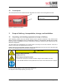
Operating Manual
redLINE RE
Gravity Convection Oven
Model
Art. no.
RE 53 (230 V)
9090-0001, 9190-0001
RE 53-UL (100-120 V)
9090-0002, 9190-0002
RE 115 (230 V)
9090-0007, 9190-0007
RE 115-UL (100-120 V)
9090-0008, 9190-0008
redLINE RF
Mechanical Convection Oven
Model
Art. no.
RF 53 (230 V)
9090-0003, 9190-0003
RF 53-UL (100-120 V)
9090-0004, 9190-0004
RF 115 (230 V)
9090-0009, 9190-0009
RF 115-UL (100-120 V)
9090-0010, 9190-0010
redLINE RI
Incubator
Model
Art. no.
RI 53 (230 V)
9090-0005, 9190-0005
RI 53-UL (100-120 V)
9090-0006, 9190-0006
RI 115 (230 V)
9090-0011, 9190-0011
RI 115-UL (100-120 V)
9090-0012, 9190-0012
www.binder-redline.com
Issue 07/2010
Art. No. 7001-0201
EC – Declaration of Conformy redLINE RE
EG – KONFORMITÄTSERKLÄRUNG
EC - DECLARATION OF CONFORMITY
CE - DECLARATION DE CONFORMITE
Anbieter / Supplier / Fournisseur:
Anschrift / Address / Adresse:
Produkt / Product / Produit:
BINDER GmbH
Im Mittleren Ösch 5, D-78532 Tuttlingen
Trockenschränke mit natürlicher Umluft
Gravity Convection Ovens
Etuves de séchage à circulation d’air naturelle
Typenbezeichnung / Type / Type:
RE 53, RE 115
Die oben beschriebenen Produkte sind konform mit folgenden EG-Richtlinien:
The products described above are in conformity with the following EC guidelines:
Les produits décrits ci-dessus sont conformes aux directives CE suivantes:
Niederspannungsrichtlinie
2006/95/EG
Low voltage directive
2006/95/EC
Directive basse tension
2006/95/CE
Richtlinie 2006/95/EG des Europäischen Parlaments und des Rates
vom 12. Dezember 2006 zur Angleichung der Rechtsvorschriften der
Mitgliedstaaten betreffend elektrische Betriebsmittel zur Verwendung
innerhalb bestimmter Spannungsgrenzen
Council Directive 2006/95/EC of 12 December 2006 on the
harmonization of the laws of Member States relating to electrical
equipment designed for use within certain voltage limits
Directive 2006/95/CE du Parlement Européen et du Conseil du 12
décembre 2006 concernant le rapprochement des législations des États
membres relatives au matériel électrique destiné à être employé dans
certaines limites de tension
EMV-Richtlinie
2004/108/EG
EMC Directive
2004/108/EC
Directive CEM
2004/108/CE
Richtlinie 2004/108/EG des Europäischen Parlaments und des Rates
vom 15. Dezember 2004 zur Angleichung der Rechtsvorschriften der
Mitgliedstaaten über die elektromagnetische Verträglichkeit und zur
Aufhebung der Richtlinie 89/336/EWG.
Directive 2004/108/EC of the European Parliament and of the Council
of 15 December 2004 on the approximation of the laws of the Member
States relating to electromagnetic compatibility and repealing Directive
98/336/EEC.
Directive 2004/108/CE du Parlement Européen et du Conseil du 15
décembre 2004 relative au rapprochement des législations des États
membres concernant la compatibilité électromagnétique et abrogeant le
directive 98/336/CEE.
Die oben beschriebenen Produkte tragen entsprechend die Kennzeichnung CE.
The products described above, corresponding to this, bear the CE-mark.
Les produits décrits ci-dessus, en correspondance, portent l’indication CE.
1/2
Redline Operating Manual RE / RF / RI 07/2010
page 2/38
Die oben beschriebenen Produkte sind konform mit folgenden harmonisierten Normen:
The products described above are in conformity with the following harmonized standards:
Les produits décrits ci-dessus sont conformes aux normes harmonisées suivantes:
Sicherheit / safety / sécurité:
EN 61010-1:2001
EN 61010-2-010:2003
Sicherheitsbestimmungen für elektrische Mess-, Steuer-, Regel- und
Laborgeräte – Teil 1: Allgemeine Anforderungen
Safety requirements for electrical equipment for measurement, control,
and laboratory use – Part 1: General requirements
Règles de sécurité pour appareils électriques de mesurage, de
régulation et de laboratoire – Partie 1 : Prescriptions générales
Sicherheitsbestimmungen für elektrische Meß-, Steuer-, Regel- und
Laborgeräte – Teil 2-010: Besondere Anforderungen an Laborgeräte für
das Erhitzen von Stoffen
Safety requirements for electrical equipment for measurement, control,
and laboratory use – Part 2-010: Particular requirements for laboratory
equipment for the heating of materials
Règles de sécurité pour appareils électriques de mesurage, de
régulation et de laboratoire. Partie 2-010 : Prescriptions particulières
pour appareils de laboratoire utilisés pour l’échauffement des matières
EMV / EMC / CEM:
EN 61326-1:2006 + Corr. 2008 Elektrische Mess-, Steuer-, Regel- und Laborgeräte – EMVAnforderungen. Teil 1: Allgemeine Anforderungen.
Electrical equipment for measurement, control and laboratory use –
EMC requirements. Part 1: General requirements.
Matériel électrique de mesure, de commande et de laboratoire –
Exigences relatives à la CEM. Partie 1: Exigences générales.
EN 61326-2-2:2006
Elektrische Mess-, Steuer-, Regel- und Laborgeräte – EMVAnforderungen. Teil 2-2: Besondere Anforderungen - Prüfanordnung,
Betriebsbedingungen und Leistungsmerkmale für ortsveränderliche
Prüf-, Mess- und Überwachungsgeräte in NiederspannungsStromversorgungsnetzen.
Electrical equipment for measurement, control and laboratory use –
EMC requirements. Part 2-2: Particular requirements - Test
configurations, operational conditions and performance criteria for
portable test, measuring and monitoring equipment used in low-voltage
distribution systems.
Matériel électrique de mesure, de commande et de laboratoire –
Exigences relatives à la CEM. Partie 2-2: Exigences particulières Configurations d’essai, conditions de fonctionnement et critères
d’aptitude à la fonction des matériels portatifs d’essai, de mesure et de
surveillance utilisés dans des systèmes de distribution basse tension.
D-78532 Tuttlingen, 22.12.2009
BINDER GmbH
P. M. Binder
Dr. H. von Both
Geschäftsführender Gesellschafter
Managing Director
Directeur général
Leiter F & E
Director R & D
Chef de service R&D
2/2
Redline Operating Manual RE / RF / RI 07/2010
page 3/38
EC – Declaration of Conformy redLINE RF
EG – KONFORMITÄTSERKLÄRUNG
EC - DECLARATION OF CONFORMITY
CE - DECLARATION DE CONFORMITE
Anbieter / Supplier / Fournisseur:
Anschrift / Address / Adresse:
Produkt / Product / Produit:
BINDER GmbH
Im Mittleren Ösch 5, D-78532 Tuttlingen
Wärme-/Trockenschränke mit forcierter Umluft
Mechanical Convection Ovens
Etuves universelles à circulation d’air forcée
Typenbezeichnung / Type / Type:
RF 53, RF 115
Die oben beschriebenen Produkte sind konform mit folgenden EG-Richtlinien:
The products described above are in conformity with the following EC guidelines:
Les produits décrits ci-dessus sont conformes aux directives CE suivantes:
Niederspannungsrichtlinie
2006/95/EG
Low voltage directive
2006/95/EC
Directive basse tension
2006/95/CE
Richtlinie 2006/95/EG des Europäischen Parlaments und des Rates
vom 12. Dezember 2006 zur Angleichung der Rechtsvorschriften der
Mitgliedstaaten betreffend elektrische Betriebsmittel zur Verwendung
innerhalb bestimmter Spannungsgrenzen
Council Directive 2006/95/EC of 12 December 2006 on the
harmonization of the laws of Member States relating to electrical
equipment designed for use within certain voltage limits
Directive 2006/95/CE du Parlement Européen et du Conseil du 12
décembre 2006 concernant le rapprochement des législations des États
membres relatives au matériel électrique destiné à être employé dans
certaines limites de tension
EMV-Richtlinie
2004/108/EG
EMC Directive
2004/108/EC
Directive CEM
2004/108/CE
Richtlinie 2004/108/EG des Europäischen Parlaments und des Rates
vom 15. Dezember 2004 zur Angleichung der Rechtsvorschriften der
Mitgliedstaaten über die elektromagnetische Verträglichkeit und zur
Aufhebung der Richtlinie 89/336/EWG.
Directive 2004/108/EC of the European Parliament and of the Council
of 15 December 2004 on the approximation of the laws of the Member
States relating to electromagnetic compatibility and repealing Directive
98/336/EEC.
Directive 2004/108/CE du Parlement Européen et du Conseil du 15
décembre 2004 relative au rapprochement des législations des États
membres concernant la compatibilité électromagnétique et abrogeant le
directive 98/336/CEE.
Die oben beschriebenen Produkte tragen entsprechend die Kennzeichnung CE.
The products described above, corresponding to this, bear the CE-mark.
Les produits décrits ci-dessus, en correspondance, portent l’indication CE.
1/2
Redline Operating Manual RE / RF / RI 07/2010
page 4/38
Die oben beschriebenen Produkte sind konform mit folgenden harmonisierten Normen:
The products described above are in conformity with the following harmonized standards:
Les produits décrits ci-dessus sont conformes aux normes harmonisées suivantes:
Sicherheit / safety / sécurité:
EN 61010-1:2001
EN 61010-2-010:2003
Sicherheitsbestimmungen für elektrische Mess-, Steuer-, Regel- und
Laborgeräte – Teil 1: Allgemeine Anforderungen
Safety requirements for electrical equipment for measurement, control,
and laboratory use – Part 1: General requirements
Règles de sécurité pour appareils électriques de mesurage, de
régulation et de laboratoire – Partie 1 : Prescriptions générales
Sicherheitsbestimmungen für elektrische Meß-, Steuer-, Regel- und
Laborgeräte – Teil 2-010: Besondere Anforderungen an Laborgeräte für
das Erhitzen von Stoffen
Safety requirements for electrical equipment for measurement, control,
and laboratory use – Part 2-010: Particular requirements for laboratory
equipment for the heating of materials
Règles de sécurité pour appareils électriques de mesurage, de
régulation et de laboratoire. Partie 2-010 : Prescriptions particulières
pour appareils de laboratoire utilisés pour l’échauffement des matières
EMV / EMC / CEM:
EN 61326-1:2006 + Corr. 2008 Elektrische Mess-, Steuer-, Regel- und Laborgeräte – EMVAnforderungen. Teil 1: Allgemeine Anforderungen.
Electrical equipment for measurement, control and laboratory use –
EMC requirements. Part 1: General requirements.
Matériel électrique de mesure, de commande et de laboratoire –
Exigences relatives à la CEM. Partie 1: Exigences générales.
EN 61326-2-2:2006
Elektrische Mess-, Steuer-, Regel- und Laborgeräte – EMVAnforderungen. Teil 2-2: Besondere Anforderungen - Prüfanordnung,
Betriebsbedingungen und Leistungsmerkmale für ortsveränderliche
Prüf-, Mess- und Überwachungsgeräte in NiederspannungsStromversorgungsnetzen.
Electrical equipment for measurement, control and laboratory use –
EMC requirements. Part 2-2: Particular requirements - Test
configurations, operational conditions and performance criteria for
portable test, measuring and monitoring equipment used in low-voltage
distribution systems.
Matériel électrique de mesure, de commande et de laboratoire –
Exigences relatives à la CEM. Partie 2-2: Exigences particulières Configurations d’essai, conditions de fonctionnement et critères
d’aptitude à la fonction des matériels portatifs d’essai, de mesure et de
surveillance utilisés dans des systèmes de distribution basse tension.
D-78532 Tuttlingen, 22.12.2009
BINDER GmbH
P. M. Binder
Dr. H. von Both
Geschäftsführender Gesellschafter
Managing Director
Directeur général
Leiter F & E
Director R & D
Chef de service R&D
2/2
Redline Operating Manual RE / RF / RI 07/2010
page 5/38
EC – Declaration of Conformy redLINE RI
EG – KONFORMITÄTSERKLÄRUNG
EC - DECLARATION OF CONFORMITY
CE - DECLARATION DE CONFORMITE
Anbieter / Supplier / Fournisseur:
Anschrift / Address / Adresse:
Produkt / Product / Produit:
BINDER GmbH
Im Mittleren Ösch 5, D-78532 Tuttlingen
Brutschränke mit natürlicher Umluft
Incubators with natural convection
Incubateurs à circulation d’air naturelle
Typenbezeichnung / Type / Type:
RI 53, RI 115
Die oben beschriebenen Produkte sind konform mit folgenden EG-Richtlinien:
The products described above are in conformity with the following EC guidelines:
Les produits décrits ci-dessus sont conformes aux directives CE suivantes:
Niederspannungsrichtlinie
2006/95/EG
Low voltage directive
2006/95/EC
Directive basse tension
2006/95/CE
Richtlinie 2006/95/EG des Europäischen Parlaments und des Rates
vom 12. Dezember 2006 zur Angleichung der Rechtsvorschriften der
Mitgliedstaaten betreffend elektrische Betriebsmittel zur Verwendung
innerhalb bestimmter Spannungsgrenzen
Council Directive 2006/95/EC of 12 December 2006 on the
harmonization of the laws of Member States relating to electrical
equipment designed for use within certain voltage limits
Directive 2006/95/CE du Parlement Européen et du Conseil du 12
décembre 2006 concernant le rapprochement des législations des États
membres relatives au matériel électrique destiné à être employé dans
certaines limites de tension
EMV-Richtlinie
2004/108/EG
EMC Directive
2004/108/EC
Directive CEM
2004/108/CE
Richtlinie 2004/108/EG des Europäischen Parlaments und des Rates
vom 15. Dezember 2004 zur Angleichung der Rechtsvorschriften der
Mitgliedstaaten über die elektromagnetische Verträglichkeit und zur
Aufhebung der Richtlinie 89/336/EWG.
Directive 2004/108/EC of the European Parliament and of the Council
of 15 December 2004 on the approximation of the laws of the Member
States relating to electromagnetic compatibility and repealing Directive
98/336/EEC.
Directive 2004/108/CE du Parlement Européen et du Conseil du 15
décembre 2004 relative au rapprochement des législations des États
membres concernant la compatibilité électromagnétique et abrogeant le
directive 98/336/CEE.
Die oben beschriebenen Produkte tragen entsprechend die Kennzeichnung CE.
The products described above, corresponding to this, bear the CE-mark.
Les produits décrits ci-dessus, en correspondance, portent l’indication CE.
1/2
Redline Operating Manual RE / RF / RI 07/2010
page 6/38
Die oben beschriebenen Produkte sind konform mit folgenden harmonisierten Normen:
The products described above are in conformity with the following harmonized standards:
Les produits décrits ci-dessus sont conformes aux normes harmonisées suivantes:
Sicherheit / safety / sécurité:
EN 61010-1:2001
EN 61010-2-010:2003
Sicherheitsbestimmungen für elektrische Mess-, Steuer-, Regel- und
Laborgeräte – Teil 1: Allgemeine Anforderungen
Safety requirements for electrical equipment for measurement, control,
and laboratory use – Part 1: General requirements
Règles de sécurité pour appareils électriques de mesurage, de
régulation et de laboratoire – Partie 1 : Prescriptions générales
Sicherheitsbestimmungen für elektrische Meß-, Steuer-, Regel- und
Laborgeräte – Teil 2-010: Besondere Anforderungen an Laborgeräte für
das Erhitzen von Stoffen
Safety requirements for electrical equipment for measurement, control,
and laboratory use – Part 2-010: Particular requirements for laboratory
equipment for the heating of materials
Règles de sécurité pour appareils électriques de mesurage, de
régulation et de laboratoire. Partie 2-010 : Prescriptions particulières
pour appareils de laboratoire utilisés pour l’échauffement des matières
EMV / EMC / CEM:
EN 61326-1:2006 + Corr. 2008 Elektrische Mess-, Steuer-, Regel- und Laborgeräte – EMVAnforderungen. Teil 1: Allgemeine Anforderungen.
Electrical equipment for measurement, control and laboratory use –
EMC requirements. Part 1: General requirements.
Matériel électrique de mesure, de commande et de laboratoire –
Exigences relatives à la CEM. Partie 1: Exigences générales.
EN 61326-2-2:2006
Elektrische Mess-, Steuer-, Regel- und Laborgeräte – EMVAnforderungen. Teil 2-2: Besondere Anforderungen - Prüfanordnung,
Betriebsbedingungen und Leistungsmerkmale für ortsveränderliche
Prüf-, Mess- und Überwachungsgeräte in NiederspannungsStromversorgungsnetzen.
Electrical equipment for measurement, control and laboratory use –
EMC requirements. Part 2-2: Particular requirements - Test
configurations, operational conditions and performance criteria for
portable test, measuring and monitoring equipment used in low-voltage
distribution systems.
Matériel électrique de mesure, de commande et de laboratoire –
Exigences relatives à la CEM. Partie 2-2: Exigences particulières Configurations d’essai, conditions de fonctionnement et critères
d’aptitude à la fonction des matériels portatifs d’essai, de mesure et de
surveillance utilisés dans des systèmes de distribution basse tension.
D-78532 Tuttlingen, 22.12.2009
BINDER GmbH
P. M. Binder
Dr. H. von Both
Geschäftsführender Gesellschafter
Managing Director
Directeur général
Leiter F & E
Director R & D
Chef de service R&D
2/2
Redline Operating Manual RE / RF / RI 07/2010
page 7/38
UL certificate, valid for redLINE-UL units
RE 53-UL, RE 115-UL, RF 53-UL, RF 115-UL, RI 53-UL, RI 115-UL
Redline Operating Manual RE / RF / RI 07/2010
page 8/38
Content
EC – Declaration of Conformy redLINE RE ..................................................................................................2
EC – Declaration of Conformy redLINE RF ..................................................................................................4
EC – Declaration of Conformy redLINE RI....................................................................................................6
UL certificate, valid for redLINE-UL units ......................................................................................................8
1.
SAFETY................................................................................................................ 11
1.1
1.2
Legal considerations .........................................................................................................................11
Structure of the safety instructions....................................................................................................11
1.2.1 Signal word panel ........................................................................................................................11
1.2.2 Safety alert symbol ......................................................................................................................12
1.2.3 Pictograms ...................................................................................................................................12
1.2.4 Word message panel structure....................................................................................................13
1.3 Localization / position of safety labels on the unit.............................................................................13
1.4 Type plate .........................................................................................................................................14
1.5 General safety instructions on installing and operating the redLINE chambers...............................15
1.6 Intended use .....................................................................................................................................16
2.
UNIT DESCRIPTION ............................................................................................ 17
2.1
2.2
2.3
Scope of delivery...............................................................................................................................17
Equipment overview..........................................................................................................................18
Control panel.....................................................................................................................................19
3.
SCOPE OF DELIVERY, TRANSPORTATION, STORAGE, AND INSTALLATION19
3.1
3.2
3.3
3.4
3.5
Unpacking, and checking equipment and scope of delivery.............................................................19
Guidelines for safe lifting and transportation ....................................................................................20
Storage..............................................................................................................................................20
Location of installation and ambient conditions ................................................................................20
Stacking ............................................................................................................................................21
4.
INSTALLATION OF THE EQUIPMENT ............................................................... 22
4.1
4.2
Electrical connection .........................................................................................................................22
Connection to a suction plant (optional) ...........................................................................................23
5.
START UP ............................................................................................................ 24
5.1
5.2
5.3
Adjusting the air change ...................................................................................................................24
Controller overview ...........................................................................................................................25
Switching on the unit .........................................................................................................................26
6.
OPERATING THE CONTROLLER....................................................................... 26
6.1
6.2
Continuous operation........................................................................................................................27
Timer operation .................................................................................................................................27
7.
CALIBRATING AND ADJUSTING THE TEMPERATURE CONTROLLER......... 28
8.
CLEANING AND DECONTAMINATION .............................................................. 29
8.1
8.2
Cleaning ............................................................................................................................................29
Decontamination ...............................................................................................................................30
9.
DECOMMISSIONING ........................................................................................... 30
10. MAINTENANCE ................................................................................................... 31
10.1 Maintenance plan..............................................................................................................................31
Redline Operating Manual RE / RF / RI 07/2010
page 9/38
11. TECHNICAL SERVICE......................................................................................... 31
12. DISPOSAL............................................................................................................ 32
12.1 Disposal of the transport packing .....................................................................................................32
12.2 Disposal of redLINE chambers in the member states of the EC ......................................................32
12.3 Disposal of redLINE chambers in non-member states of the EC .....................................................33
13. TROUBLESHOOTING ......................................................................................... 34
14. TECHNICAL DESCRIPTION................................................................................ 35
14.1
14.2
14.3
14.4
14.5
Factory calibration and adjustment ...................................................................................................35
Over current protection .....................................................................................................................35
Definition of usable space.................................................................................................................35
Technical data...................................................................................................................................36
Equipment .........................................................................................................................................37
Redline Operating Manual RE / RF / RI 07/2010
page 10/38
Dear customer,
For the correct operation of the redLINE chambers, it is imperative that you read this operating manual
completely and carefully and observe the given instructions.
1.
Safety
This operating manual is part of the scope of delivery. Always keep it at hand.
To avoid injuries and damage observe the safety instructions of the operating manual.
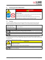
WARNING
Failure to observe the safety instructions.
Serious injuries and unit damage.
¾ Observe the safety instructions in this operating manual.
¾ Carefully read the complete operating instructions of the redLINE chambers.
1.1
Legal considerations
This operating manual contains information necessary for the intended use, correct installation, start-up
and operation, and for the maintenance of the unit.
Understanding and observing the instructions in this operating manual are prerequisites for hazard-free
use and safety during operation and maintenance.
This operating manual cannot cover all conceivable applications. If you would like additional information,
or if special problems arise that you feel are not sufficiently addressed in this manual, please ask your
dealer or contact us directly.
Furthermore, we emphasize that the contents of this operating manual are not part of an earlier or
existing agreement, promise, or legal relationship, nor do they modify such a relationship. All obligations
on the part of the manufacturer derive from the respective purchase contract, which also contains the
entire and exclusively valid statement of warranty administration. The statements in this manual neither
augment nor restrict the contractual warranty provisions.
1.2
Structure of the safety instructions
In this operating manual, the following harmonized denominations and symbols indicate dangerous
situations following the harmonization of ISO 3864-2 and ANSI Z535.6.
1.2.1
Signal word panel
Depending on the seriousness and probability of the consequences, dangers are identified with a signal
word, the corresponding safety color, and if appropriate, the safety alert symbol.
DANGER
Indicates an imminently hazardous situation that, if not avoided, will result in death or serious
(irreversible) injury.
WARNING
Indicates a potentially hazardous situation which, if not avoided, could result in death or serious
(irreversible) injury
Redline Operating Manual RE / RF / RI 07/2010
page 11/38
CAUTION
Indicates a potentially hazardous situation which, if not avoided, may result in moderate or minor
(reversible) injury
CAUTION
Indicates a potentially hazardous situation which, if not avoided, may result in damage to the product
and/or its functions or of a property in its proximity.
1.2.2
Safety alert symbol
Use of the safety alert symbol indicates risk of injury.
Observe all measures that are marked with the safety alert symbol in order to avoid death or
injury.
1.2.3
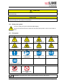
Pictograms
Warning signs
Electrical hazard
Hot surface
Explosive atmosphere
Stability hazard
Pollution Hazard
Harmful substances
Biohazard
Lifting hazard
Read operating
instructions
Disconnect the power
plug
Lift with several persons
Mandatory action signs
Mandatory regulation
Environment protection
Prohibition signs
Do NOT touch
Do NOT spray with
water
Information to be observed in order to ensure optimum function of the product.
Redline Operating Manual RE / RF / RI 07/2010
page 12/38
1.2.4
Word message panel structure
Type / cause of hazard.
Possible consequences.
∅ Instruction how to avoid the hazard: prohibition.
¾ Instruction how to avoid the hazard: mandatory action.
Observe all other notes and information not necessarily emphasized in the same way, in order to avoid
disruptions which could result in direct or indirect injury or property damage.
1.3
Localization / position of safety labels on the unit
The following labels are located on the unit:
Pictograms (Warning signs)
Risk of injury (UL units only)
Hot surface
redLINE
redLINE-UL
Figure 1: Position of labels on the unit
Keep safety labels complete and legible.
Replace safety labels that are no longer legible. Call up www.binder-redline.com.
Redline Operating Manual RE / RF / RI 07/2010
page 13/38
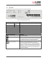
1.4
Type plate
The type plate is located on the left-hand side of the unit, bottom right-hand.
Nominal temperature
Enclosure protection
Art. No.
220 °C
428°F
IP 20
9090-0001
0,80
230
3,5
50/60
kW
V1N~
A
Hz
RE 53 Serial No. RE-000000-00000
www.binder-redline.com
Made by BINDER in Germany
Figure 2: Type plate (example: RE 53)
Indications of the type plate
Nominal temperature
220 °C
428°F
Enclosure protection
IP 20
Art. No.
9090-0001
0,80 kW
230 V 1 N ~
3,5 A
50/60 Hz
RE 53
Serial No. RE-000000-00000
Information
Nominal temperature
IP type of protection 20 acc. to EN 60529
Article number 9090-0001
Nominal power 0.80 kW
Nominal voltage 230 V ± 10%, single-phase unit
Nominal current 3.5 Amp
Power frequency 50/60 Hz
Model RE 53
Serial No. RE-000000-00000
Symbol on the type plate
Information
CE conformity marking
Electrical and electronic equipment manufactured / placed on
the market in the EC after 13 August 2005 and to be disposed
of in a separate collection according to directive 2002/96/EC
on waste electrical and electronic equipment (WEEE).
(UL units only)
LABORATORY EQUIPMENT
43KM
The equipment is certified by Underwriters Laboratories Inc.®
according to standards CAN/CSA-C22.2 No. 61010-1, 2nd
Edition, 2004-07 (Electrical Equipment for Measurement,
Control, and Laboratory Use; Part 1: General Requirements);
UL 61010-1, 2nd Edition, 2005-07-22 (Electrical Equipment for
Measurement, Control, and Laboratory Use; Part 1: General
Requirements); IEC 61010-1:2001, 2nd Edition and IEC 610102-10 (Particular Requirements for Laboratory Equipment for
the heating of materials).
Redline Operating Manual RE / RF / RI 07/2010
page 14/38
1.5
General safety instructions on installing and operating the redLINE
chambers
With regard to operating the redLINE chambers and to their installation location, please observe
regulations BGR 120 issued by the German professional association for the chemical industry (formerly
ZH 1/119 laboratory guidelines issued by the employers’ liability insurance association) (for Germany).
The manufacturer is only responsible for the safety features of the unit provided skilled electricians or
qualified personnel authorized by the manufacturer perform all maintenance and repair, and if
components relating to chamber safety are replaced in the event of failure with original spare parts.
To operate the unit, use only original accessories or accessories from third-party suppliers authorized by
the manufacturer. The user is responsible for any risk caused by using unauthorized accessories.
CAUTION
Danger of overheating.
Damage to the unit.
∅ Do NOT install redLINE chambers in unventilated recesses.
¾ Ensure sufficient ventilation for dispersal of the heat.
The redLINE chambers must NOT be operated in hazardous locations.
DANGER
Explosion hazard.
Danger of death.
∅ Do NOT operate redLINE chambers in potentially explosive areas.
¾ KEEP explosive dust or air-solvent mixtures AWAY from the unit.
The redLINE chambers do not dispose of any measures of explosion protection.
DANGER
Explosion hazard.
Danger of death.
∅ Do NOT introduce any combustible or explosive substance at working temperature into
the redLINE chambers.
∅ NO explosive dust or air-solvent mixture in the inner chamber.
Any solvent contained in the charging material must not be explosive or inflammable. I.e., irrespective of
the solvent concentration in the steam room, NO explosive mixture with air must form. The temperature
inside the chamber must lie below the flash point or below the sublimation point of the charging material.
Familiarize yourself with the physical and chemical properties of the charging material, as well as the
contained moisture constituent and its behavior with the addition of heat energy.
Familiarize yourself with any potential health risks caused by the charging material, the contained
moisture constituent or by reaction products that may arise during the temperature process. Take
adequate measures to exclude such risks prior to putting the unit into operation.
Redline Operating Manual RE / RF / RI 07/2010
page 15/38
DANGER
Electrical hazard.
Danger of death.
∅ The unit must NOT become wet during operation or maintenance.
redLINE chambers have been produced in accordance with VDE regulations and were routinely tested in
accordance to VDE 0411-1 (IEC 61010-1).
CAUTION
The inner chamber and the outgoing air pipe will become hot during operation.
Danger of burning.
∅ Do NOT touch the inner surfaces, the access ports, or the charging material during
operation.
1.6
Intended use
Gravity convection ovens RE and mechanical convection ovens RF are designed for all standard
drying and tempering tasks as well as sterilizing glassware. They are intended for use in biological,
chemical, medical, pharmaceutical and physical laboratories.
Incubators RI are designed to cultivate microorganisms at defined temperatures. They can be used e. g.
for determining the number of microorganisms through plate count methods or detecting of pathogenic
germs, e.g. in product samples. They are intended for use in biological, chemical, medical, and
pharmaceutical laboratories.
Any solvent content must not be explosive or flammable. A mixture of any component of the charging
material with air must NOT be explosive. The operating temperature must lie below the flash point or
below the sublimation point of the charging material.
Other applications are not approved.
Do NOT use redLINE chambers for drying purpose if greater quantities of steam leading to condensation
will be set free.
Observing the instructions in this operating manual and conducting regular maintenance work
(chap. 10) is part of the intended use.
Due to the special demands of the Medical Device Directive (MDD) this ovens are not qualified for
sterilization of medical devices as defined by the directive 93/42/EWG.
Redline Operating Manual RE / RF / RI 07/2010
page 16/38
2.
Unit description
Function
Gravity convection ovens RE and mechanical convection ovens RF are suitable for drying and heat
treatment of solid or pulverized charging material, as well as bulk material, using the supply of heat. They
are designed for all standard drying and tempering tasks as well as sterilizing glassware. RF permits
shorter drying times.
The incubators RI are designed for exact temperation of harmless materials. They are designed to
cultivate microorganisms at defined temperatures.
Controller
redLINE chambers are equipped with an electronic PID-controller with digital display. The ovens RE and
RF have a temperature display and setting with an accuracy of one degree. The incubators RI have a
temperature display and setting with an accuracy of a tenth of a degree. The integrated timer can be set
to 0-9999 minutes. Also continuous operation is possible.
Interior and housing
The inner chamber, the pre-heating chamber and the inside of the doors are all made of stainless steel.
When operating the ovens RE and RF at temperatures above 150 °C / 302°F, the influence of the oxygen
in the air may cause coloration of the metallic surfaces (yellowish-brown or blue) by natural oxidation
processes. These colorations are harmless and will in no way impair the function or quality of the unit.
The housing is RAL 7035 powder-coated. All corners and edges are completely coated.
Heating and ventilation
redLINE chambers are heated electrically and ventilated naturally. Mechanical convection ovens RF are
ventilated by fan-assisted, forced-air circulation. The direct heating system provides an extremely precise
internal temperature. A thermoelement serves to measure the tempering of the interior, which is
controlled by the redline controller.
Temperature range: Ovens RE and RF: by by 7 °C / 12°F above room temperature up to 220 °C / 428°F.
Incubators RI: by by 7 °C / 12°F above room temperature up to 70 °C / 158°F.
Temperature safety device
redLINE chambers are regularly equipped with a temperature safety device class 1 according to
DIN12880. The temperature fuse is triggered irreversibly if the maximum temperature of 229 °C / 444.2°F
(RE, RF) resp. 110 °C / 230°F (RI) inside the chamber is exceeded.
Electrical connection
redLINE chambers are available for a 230 V, redLINE UL chambers for a 100-120 V power supply.
2.1
Scope of delivery
• redLINE gravity convection oven RE, or redLINE mechanical convection oven RF, or redLINE
incubator RI
• 2 trays
• Flat assembly bar for stacking (it is vital to keep them, as two flat assembly bars are required to stack
two devices, and each device comes supplied with one)
Redline Operating Manual RE / RF / RI 07/2010
page 17/38
2.2
Equipment overview
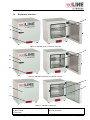
(4)
(1)
(2)
(3)
Figure 3: redLINE gravity convection oven RE
(4)
(1)
(2)
(3)
Figure 4: redLINE mechanical convection oven RF
(4)
(5)
(1)
(3)
Figure 5: redLINE incubator RI
(1) Chamber door
(2) Door handle
(3) Controller
Redline Operating Manual RE / RF / RI 07/2010
(4) Tray
(5) Inner glass door
page 18/38
2.3
Control panel
The control panel with the controller and the main switch is located on the housing below the door.
(6)
(6) Controller
(7)
(7) Main switch
Figure 6: redLINE control panel
3.
Scope of delivery, transportation, storage, and installation
3.1
Unpacking, and checking equipment and scope of delivery
After unpacking, please check the redLINE chamber and its optional accessories, if any, based on the
delivery note for completeness and for transportation damage. If transportation damage has occurred,
inform the carrier immediately and have it confirmed on the proof of delivery by the vehicle driver who
delivers the equipment.
The final tests of the manufacturer may cause traces of the trays on the inner surfaces. This has no
impact on the function and performance of the unit.
Please remove any transportation protection devices and adhesives in/on the unit and on the doors and
take out the operating manuals and accessory equipment.
CAUTION
Sliding or tilting of the unit.
Damage to the unit.
Risk of injury by lifting heavy loads.
∅ Do NOT lift or transport a redLINE chamber using the door handle or the door.
¾ Lift a redLINE chamber from the pallet at its four lower corners with the aid of 2 people.
In case of warranty please contact www.binder-redline.com.
For disposal of the transport packing, see chap. 12.1.
Redline Operating Manual RE / RF / RI 07/2010
page 19/38
3.2
Guidelines for safe lifting and transportation
Observe the advice for temporal decommissioning (chap. 9).
CAUTION
Sliding or tilting of the unit.
Damage to the unit.
Risk of injury by lifting heavy loads.
¾ Transport the redLINE chamber in its original packaging only.
¾ Secure the redLINE chamber with transport straps for transport.
∅ Do NOT lift or transport a redLINE chamber using the door handle or the door.
¾ Lift a redLINE chamber at its four lower corners with the aid of 2 people and place it on
a transport pallet with wheels. Push the pallet to the desired site and then lift the unit
from the pallet at its four lower corners.
• Permissible ambient temperature range during transport: -10 °C / 14°F to +60 °C / 140°F.
You can order transport packing and pallets for transportation purposes via www.binder-redline.com.
3.3
Storage
Intermediate storage of the unit is possible in a closed and dry room. Observe the guidelines for
temporary decommissioning (chap. 9).
• Permissible ambient temperature range during storage: -10 °C / 14°F to +60 °C / 140°F.
• Permissible ambient humidity: max. 70 % r.H., non-condensing
If following storage in a cold location the unit is transferred to the installation site for start-up,
condensation may form. Wait at least one hour until the oven has attained ambient temperature and is
completely dry.
3.4
Location of installation and ambient conditions
Set up redLINE chambers on an even and non-flammable surface, free from vibration and in a wellventilated, dry location and align them using a spirit level. The site of installation must be capable of
supporting the unit’s weight (see technical data, chap. 14.4). Set up the chamber in such a way that tha
main switch (7) is easily accessible and can be switched off immediately in case of danger.
CAUTION
Danger of overheating.
Damage to the unit.
∅ Do NOT set up redLINE chambers in non-ventilated recesses.
¾ Ensure sufficient ventilation for dispersal of the heat.
• Permissible ambient temperature range during operation: +18 °C / 64.4°F up to +40 °C / 104°F. At
elevated ambient temperature values, fluctuations in temperature can occur.
The ambient temperature should not be substantially higher than the indicated ambient
temperature of +25 °C / 77°F to which the specified technical data relate. For other
ambient conditions, deviations from the indicated data are possible.
Redline Operating Manual RE / RF / RI 07/2010
page 20/38
• Permissible ambient humidity: 70 % r.H. max., non-condensing.
• Installation height: max. 2000 m / 6562 ft above sea level.
Maintain a minimum distance of 250 mm / 9.84 in between each unit. Wall distances: rear 100 mm / 3.94
in, sides 160 mm / 6.30 in.
To completely isolate the unit from the power supply, you must disconnect the power plug. Install the unit
in a way that the power plug is easily accessible and can be easily disconnected in case of danger.
The unit must NOT be installed and operated in hazardous locations.
DANGER
Explosion hazard.
Danger of death.
∅ Do NOT operate redLINE chambers in potentially explosive areas.
¾ KEEP explosive dust or air-solvent mixtures AWAY from the vicinity of the unit.
redLINE chambers are not waterproof. Do not install the chamber in locations where water could be
sprayed about, e.g. in the vicinity of sinks or safety showers.
DANGER
Electrical hazard.
Danger of death.
¾ redLINE chambers must NOT become wet during operation or maintenance work
3.5
Stacking
Two redLINE chambers can be piled on top of each other. To ensure that they are safely positioned, both
devices should be attached to one another using the flat assembly bars supplied. One flat assembly bar
is supplied with each redLINE chamber.
CAUTION
Sliding or tilting of the upper chamber.
Damage to the chambers.
∅ Niemals mehr als zwei redLINE chambers aufeinander stellen.
¾ Always secure stacked redLINE chambers using both flat assembly bars supplied
Redline Operating Manual RE / RF / RI 07/2010
page 21/38
• Place the first chamber at the intended location. Leave
enough space between the rear panel of the chamber
and the wall behind it, so that you can turn screws into
the rear panel using a TX20 screwdriver.
• Unscrew two of the screws which fix the upper edge of
the rear panel of the lower chamber.
• Fasten two flat assembly bars with these screws at the
upper edge of the rear panel.
• Place the second chamber on top of the first.
• Unscrew two of the screws which fix the lower edge of
the rear panel of the upper chamber.
• Place the upper chamber in a way that the empty
drilling holes overlap the holes in the lower chamber’s
flat assembly bar.
• Screw the two assembly bars to the rear panel of the
upper chamber.
Figure 7: Stacking two redLINE chambers
4.
Installation of the equipment
4.1
Electrical connection
• Power supply voltage 230 V (1N~) +/- 10 %, 50/60 Hz. UL-units: 100-120 V (1N~) +/- 10 %, 50/60 Hz
• Power connection: IEC connector plug and cable of 2500 mm / 98.4 in in length
• Plug 230 V units: shockproof plug. Plug UL-units: NEMA 5-15P
• Prior to connection and start-up, check the power supply voltage. Compare the values to the data
specified on the type plate of the unit (on the left-hand side of the unit, chap. 1.4).
• When connecting, please observe the regulations specified by the local electricity supply company
and as well as the VDE directives (for Germany)
• Pollution degree (acc. to IEC 1010-1): 2
• Over-voltage category (acc. to IEC 1010-1): II
CAUTION
Danger of incorrect power supply voltage.
Damage to the equipment.
¾ Check the power supply voltage before connection and start-up.
¾ Compare the power supply voltage with the data indicated on the type plate.
See also electrical data (chap. 14.4).
Redline Operating Manual RE / RF / RI 07/2010
page 22/38
WARNING
Danger by electrical short-circuit.
Danger of fire.
¾ Only use the chamber connected to a power source fused to at least 10 Amp.
DANGER
Electrical hazard.
Danger of death.
∅ Do not connect any chamber with a dented or damaged rear panel to the power supply.
¾ If the chamber has a damaged power cable or rear panel, withdraw it from use
immediately, remove the power plug and contact your dealer to have it repaired.
To completely isolate the unit from the power supply, you must disconnect the power plug.
Install the unit in a way that the plug is easily accessible and can be easily disconnected in
case of danger.
4.2
Connection to a suction plant (optional)
When directly connecting a suction plant the spatial temperature exactitude, the heating-up and the
recovering times and the maximum temperature will be negatively influenced. So no suction plant should
be directly connected to the outgoing air pipe.
Active suction from the oven must only be effected together with extraneous air. Perforate the
connecting piece to the suction device or place an exhaust funnel at some distance to the
outgoing air pipe.
CAUTION
The exhaust duct and its cover will become hot during operation.
Danger of burning.
∅ Do NOT touch the exhaust duct and its cover during operation.
Redline Operating Manual RE / RF / RI 07/2010
page 23/38
5.
Start up
5.1
Adjusting the air change
The air flap on top on the inner back wall serves to adjust the air change.
Without connecting a suction plant:
• RI and RE: Fresh air circulation can be elevated using the outgoing air pipe. The air flap in the
outgoing air pipe serves to adjust the fresh air entry.
• RF: With the air flap open and the fan operating, fresh air comes in via aeration gaps.
If the air flap is completely open, the spatial temperature accuracy may be negatively
influenced.
{ = air flap open
= air flap closed
Figure 8: Adjusting the air change RF
Figure 9: Adjusting the air change RE and RI
Adjust the air flap in a way that no condensation occurs inside the unit.
Redline Operating Manual RE / RF / RI 07/2010
page 24/38
5.2
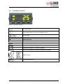
Controller overview
Figure 10: redLINE controller
Functional button
Configuration button (access to the adjusting menu)
Arrow buttons
MAN
Standby pilot lamp: heating off
OP1
Heating pilot lamp
OP2
No function
Timer: Setting the tempering time inminutes
Timer run down, controller changes to Standby mode
Change-over Standby – Continuous operation
Continuous operation (actual value equilibrates to set-point)
Adjusting menu
Correct password entry
Redline Operating Manual RE / RF / RI 07/2010
page 25/38
5.3
Switching on the unit
Insert the plug into a socket (chap. 4.1) and switch on the chamber at its main switch (7).
RF: The fan is permanently active, as long as the chamber is switched on at the main switch,
independent on the current controller function.
After switching on the chamber, the controller runs a 3 second self-test sequence displaying the software
version. Then it shows the main display (actual value display).
During the equilibration phase of an hour after switching on the chamber, undefined temperature
conditions occur within the unit. During this phase, do not place any sample materials in the chamber.
CAUTION
Danger of samples being destroyed.
¾ Load the chamber only after equilibration of temperature and CO2.
6.
Operating the controller
Controller setting is identical on all redLINE chambers. The temperature controllers only differ in their
temperature range and the temperature display and setting accuracy (RE and RF with degree accuracy,
RI with accuracy of a tenth of a degree).
After switching on the chamber at the main switch (7), the controller is in Continuous operation or
Standby mode, dependent on which was the operating mode before switching off the chamber.
Continuous operation: The display shows the actual temperature value. See chap. 6.1.
Standby: The display shows the actual temperature value alternating with
is lit. See chap. 6.2.
. The LED MAN (Standby)
To view the current set-point press one of the arrow buttons. The set-point is displayed for 2 seconds.
To view the temperature unit, shortly press the configuration button
unit °C or °F is displayed for 2 seconds
or the functional button
. The
and the functional button
together will always return you to the
Pressing the configuration button
actual value display. If, at any time, no key is pressed within 45 seconds, the display will always return to
the actual value display.
To view the temperature unit, shortly press the configuration button
unit °C or °F is displayed for 2 seconds.
or the functional button
The display ACCS, which appears after pressing several times the configuration button
function
. The
, has no
You can operate the controller in two operating modes: Continuous operation (chap. 6.1) and Timer
operation (chap. 6.2).
Controller adjustment is described in chap. 7.
During the equilibration phase of an hour after switching on the chamber, undefined temperature
conditions occur within the unit. During this phase, do not place any sample materials in the chamber.
CAUTION
Danger of samples being destroyed.
¾ Load the chamber only after equilibration of temperature and CO2.
Redline Operating Manual RE / RF / RI 07/2010
page 26/38
6.1
Continuous operation
The display shows the actual temperature value. The actual value reaches the set-point and equilibrates
to it.
Setting the temperature set-point:
Press one of the arrow buttons. The set-point is displayed for 2 seconds. Set the set-point with the arrow
buttons.
Now the controller operates until cancellation with the entered set-point in continuous operation. The
heating is active.
6.2
Timer operation
You can use the timer function to switch off the incubator heating after a defined time. You can set the
timer from 0 up to 9999 minutes.
The set-point which has been entered in Continuous operation is valid also for timer operation.
1. Set the set-point with the arrow buttons.
2. Press the functional button
several times until
appears.
3. Set the tempering time in minutes with the arrow buttons.
4. As soon as a value > 0 was entered for the tempering time, the timer starts with the enered time. The
set-point is reached ans equilibrated. Indication
.
The timer counts down towards zero.
During timer operation you can increase or decrease the remaining time according to the demands of
the process. And you can change to the actual value display and modify the set-point value without
interrupting timer operation.
To terminate the timer you need to set the value to zero or switch off the chamber.
5. When the timer is run-down, the indication
flashes on the controller display, and the controller
changes to Standby mode. This can be recognized by the LED MAN which is lit. In Standby mode the
heating is switched off, i.e., the chamber wil cool down.
will last until either you enter a new value for the tempering time and so
The flashing indication
start again the timer, or you reset the timer.
Repeated Timer operation
• Press the functional button
several times until
appears.
• Enter a new value for the tempering time with the arrow buttons. The timer starts with the enered time.
Changing to Continuous operation
• Timer reset: press down the configuration button
and the functional button
simultaneously.
The flashing indication
goes off. The controller remains in Standby mode (LED MAN is lit).
several times
• Change from Standby mode to Continuous operation: press the functional button
until
appears. Select the desired operating mode
(Continuous operation) with the arrow
buttons.
• The actual value reaches the set-point and equilibrates to it.
Redline Operating Manual RE / RF / RI 07/2010
page 27/38
7.
Calibrating and adjusting the temperature controller
Check the temperature controller for accuracy every year (calibration) and, if necessary, adjust it
(adjustment).
Required measuring equipment
An electronic measuring and display device with a valid calibration certificate and which has been
approved by a recognized standards or calibration authority or regulatory body.
RE / RF: Measuring range: ≥ 20 °C / 68°F up to 250 °C / 482°F
RI: Measuring range: ≥ 20 °C / 68°F up to 70 °C / 158°F at 10 % r.H. to 70 % r.H.
The sensor should be connected to the display instrument via a slim cable that can be placed over the
door gasket of the redLINE chamber without this causing a leak.
Check (calibration)
• Attach the temperature sensor of the reference measuring device to a tray in the center of the usable
volume and place the sensor cable over the door gasket in a way that it is possible to close the glass
door (RI) and the chamber door. Close the glass door (RI) and the chamber door.
• Switch on the redLINE chamber and set the lower adjustment temperature. Wait for 60 minutes after
the interior temperature has first reached the set-point to permit equilibrating.
• Compare the temperature displayed on the controller display to the reading of the reference
measuring device. Note down the value of the reference measuring device and the difference to the
value shown on the controller.
• Then set the upper adjustment temperature. Wait for 60 minutes after the interior temperature has first
reached the set-point to permit equilibrating.
• Compare the temperature displayed on the controller display to the reading of the reference
measuring device. Note down the value of the reference measuring device and the difference to the
value shown on the controller.
Adjusting the temperature controller is necessary if the temperature displayed on the controller deviates
by more than ±1 K (RE / RF) resp. ±0.5 K (RI) from the temperature shown by the reference measuring
device.
Adjustment (two-point adjustment)
• Press the configuration button
• Press the functional button
twice to access the input menu
to select the parameter
• Enter the password 1 with the arrow keys.
• Press the functional button
• Select
.
.
will be displayed.
to select the parameter
.
with the arrow buttons
you can call up the four adjustment parameters one after the other
• With the functional button
(
and
are displayed only after setting the first 2 parameters). Use the arrow keys to set
the temperature values of the reference measuring device and the corresponding offset values.
Temperature value of the reference measuring device at the lower adjustment temperature
Offset value at the lower adjustment temperature (difference noted during calibration)
Temperature value of the reference measuring device at the upper adjustment temperature
Offset value at the upper adjustment temperature (difference noted during calibration)
The temperature controller of your redLINE chamber has now been adjusted.
Redline Operating Manual RE / RF / RI 07/2010
page 28/38
8.
Cleaning and decontamination
DANGER
Electrical hazard.
Danger of death.
∅ Do NOT spill water or cleaning agents over the inner and outer surfaces.
∅ Do NOT dismount the rear panel of the unit.
¾ Disconnect the chamber before cleaning. Disconnect the power plug.
¾ Completely dry the appliance before switching it on again.
8.1
Cleaning
Disconnect redLINE chambers from the power supply before cleaning. Disconnect the power plug.
Wipe the surfaces with a moistened towel. In addition, you can use the following cleaning agents:
Exterior surfaces, inner
chamber, trays, door
gaskets, glass door (RI)
Standard commercial cleaning detergents free from acid or halogenides.
Instrument panel
Standard commercial cleaning detergents free from acid or halogenides.
Alcoholic solutions.
For surface protection, perform cleaning as quickly as possible.
After cleaning completely remove cleaning agents from the surfaces with a moistened towel.
Soapsuds may contain chlorides and must therefore NOT be used for cleaning.
Thoroughly remove all residues of cleaning agents from the interior with sterile (RI), deionized water.
RI: Use sterile cloths to dry off any residual water adhering to the interior of the incubator and the inside
of the glass door.
If necessary, ventilate the interior thoroughly.
CAUTION
Danger of corrosion.
Damage to the chamber.
∅ Do NOT use acidic or chlorine cleaning detergents.
Any corrosive damage that may arise following use of other cleaning agents is excluded from
liability by the manufacturer.
Redline Operating Manual RE / RF / RI 07/2010
page 29/38
CAUTION
Residual cleaning agents.
Danger of samples being disturbed.
∅ Any residual cleaning agents in the chamber may pollute the samples.
8.2
Decontamination
Disconnect redLINE chambers from the power supply prior to decontamination. Pull the power plug.
You can use the following disinfectants:
Inner chamber
Standard commercial surface disinfectants free from acid or halogenides.
Alcoholic solutions.
In case of impurity of the interior with biological or chemical hazardous goods, there are three possible
procedures depending on the type of contamination and of the charging material.
• The ovens RE and RF can be hot air sterilized at 190 °C / 374°F for at least 30 minutes. All
inflammable goods must be removed from the interior before.
• Spray the inner chamber with an appropriate disinfectant.
Before start-up, redLINE chambers must be absolute dry and ventilated, because explosive gases
may form during the decontamination process.
• If necessary, have strongly contaminated inner chamber parts removed by an engineer for cleaning,
or have them exchanged. Sterilize the inner chamber parts in a sterilizer or autoclave.
With every decontamination method, ensure adequate personal safety.
Thoroughly remove all residues of disinfecting agents from the interior with sterile (RI), deionized water.
If necessary, ventilate the interior thoroughly.
CAUTION
Residual disinfecting agents.
Danger of samples being disturbed.
∅ Any residual disinfecting agents in the chamber may pollute the samples.
9.
Decommissioning
Switch off the redLINE chamber at the main switch (7). Disconnect the chamber from the power supply.
When switching off the main switch (7), the stored parameters remain saved.
• Clean the redLINE chamber and its trays and dry them completely.
• Temporal decommissioning: See indications for appropriate storage, chap. 3.3.
• Final decommissioning: Dispose of the unit as described in chap. 12.2 to 12.3.
Redline Operating Manual RE / RF / RI 07/2010
page 30/38
10.
Maintenance
DANGER
Electrical hazard.
Danger of death.
∅ redLINE chambers must NOT become wet during operation or maintenance work.
∅ Do NOT dismount the rear panel of the unit.
¾ Disconnect the chamber before conducting maintenance work. Disconnect the power
plug.
¾ Ensure all maintenance work is conducted by licensed electricians or experts
authorized by the manufacturer.
10.1
Maintenance plan
Weekly
• Dust the housing.
• Check the power cable for damage
Following use
• Clean and, if necessary, disinfect the chamber (chap. 8)
• Check the chamber for mechanical damage and corrosion
• Check the door gaskets for proper fit and mechanical damage
Annually
• Check the temperature controller and, if necessary, adjust it (chap. 7)
Replace the door gasket only when cold. Otherwise, the door gasket may become damaged.
11.
Technical service
Web ressources
Visit the website www.binder-redline.com for:
• Complete technical service contact information
• Access to the online catalogue, and information about accessories and related products.
• Additional product information and special offers
Contact us
For information or technical assistance contact your local distributor or visit www.binder-redline.com.
Redline Operating Manual RE / RF / RI 07/2010
page 31/38
12.
Disposal
12.1
Disposal of the transport packing
We recommend keeping the transport packing for transport purpose.
Packing element
Straps to fix packing on pallet
Pallet (size 115)
with foamed plastic stuffing
Transport box
with metal clamps
Edge protection
Protection of doors and trays
Bag for operating manual
Insulating air cushion foil (packing of
optional accessories)
Material
Plastic
Solid wood (IPPC standard)
PE foam
Cardboard
Metal
Styropor® or PE foam
PE foam
PE foil
PE foil
Disposal
Plastic recycling
Wood recycling
Plastic recycling
Paper recycling
Metal recycling
Plastic recycling
Plastic recycling
Plastic recycling
Plastic recycling
If recycling is impossible, all packing parts can also be disposed of with normal waste.
12.2
Disposal of redLINE chambers in the member states of the EC
According to directive 2002/96/EC of the European Parliament and of the Council on waste electrical and
electronic equipment (WEEE), redLINE chambers are classified as “monitoring and control instruments”
(category 9) only intended for professional use“. They must not be disposed of at public collecting points.
redLINE chambers bear the symbol for the marking of electrical and electronic equipment
manufactured / placed on the market in the EC after 13 August 2005 and be disposed of in
separate collection according to the directive 2002/96/EC on waste electrical and electronic
equipment (WEEE). WEEE marking: crossed-out wheeled bin with solid bar under.
At the end of the device’s service life, notify the distributor who sold you the device, who will
take back and dispose of the unit according to the directive 2002/96/EC of 27 January 2003
on waste electrical and electronic equipment (WEEE).
CAUTION
Violation against existing law.
∅ Do NOT dispose of redLINE chambers at public collecting points.
¾ Have the redLINE chambers disposed of professionally at a recycling company which
is certified according to conversion of the directive 2002/96/EC into national law.
or
¾ Instruct the distributor who sold you the redLINE chambers to dispose of it. The
agreements apply that were reached with the distributor when purchasing the unit (e.g.
his general terms of payment and delivery).
Redline Operating Manual RE / RF / RI 07/2010
page 32/38
Certified companies disassemble waste redLINE chambers in primary substances for recycling according
to directive 2002/96/EC. In order to eliminate any health hazards to the employees of the recycling
companies, the devices must be free from toxic, infectious or radioactive substances.
It is the user’s responsibility that the redLINE chamber is free from toxic, infectious or
radioactive substances prior to handing it over to a recycling company.
• Prior to disposal, clean all introduced or residual toxic substances from the chamber.
• Prior to disposal, disinfect the chamber from all sources of infection. Be aware of the fact
that sources of infection may also be located outside the inner chamber.
• If you cannot safely remove all sources of infection and toxic substances from the unit,
dispose of it as special waste according to national law.
WARNING
Contamination of the device with toxic, infectious or radioactive substances.
Danger of intoxication.
Danger of infection.
∅ NEVER take redLINE chambers contaminated with toxic substances or sources of
infection for recycling according to directive 2002/96/EC.
¾ Prior to disposal, remove all toxic substances and sources of infection from the
chamber.
¾ Dispose of redLINE chambers from which all toxic substances or sources of infection
cannot be safely removed as special waste according to national law.
12.3
Disposal of redLINE chambers in non-member states of the EC
CAUTION
Alteration of the environment.
¾ Observe the statutory regulations for appropriate, environmentally friendly disposal.
The main board of the oven includes a lithium cell. Please dispose of it according to national regulations.
Redline Operating Manual RE / RF / RI 07/2010
page 33/38
13.
Troubleshooting
Fault description
Unit without function.
Possible fault cause
Unit switched off
No power supply.
Wrong voltage.
Unit fuse has responded.
Controller defective.
Set-point temperature is not
reached after specified time.
Chamber heating permanently,
set-point not held.
Chamber doesn’t heat up.
Heating pilot lamp OP1 is lit.
Chamber doesn’t heat up.
Heating pilot lamp OP1 is not lit.
Controller indicates the actual
value.
Chamber doesn’t heat up.
Heating pilot lamp OP1 is not lit.
Stand-by pilot lamp MAN is lit.
Controller indicates the actual
.
value alternating with
Chamber doesn’t heat up.
Heating pilot lamp OP1 is not lit.
Stand-by pilot lamp MAN is lit.
Controller indicates the actual
value.
Deviations from the indicated
heating-up times.
The controller returns to the
actual value display from any
level.
Unit door not properly closed.
Door gasket defective.
Controller not adjusted, or
adjustment interval exceeded.
Controller defective.
Temperature sensor
defective.
Semiconductor relay
defective.
Controller not adjusted, or
adjustment interval exceeded.
Heating element defective.
Semiconductor relay
defective.
Semiconductor relay
defective.
Controller defective.
Required measures
Switch on the unit at the main switch
(7).
Check connection to power supply.
Check power supply for voltage of
100-120V or 230V..
Check unit fuse and replace it if
appropriate. If it responds again,
contact a service tecnician (for
qualification see Service Manual).
Contact a service tecnician (for
qualification see Service Manual).
Close unit door properly.
Replace door gasket.
Calibrate and adjust controller.
Contact a service tecnician (for
qualification see Service Manual).
Calibrate and adjust controller.
Contact a service tecnician (for
qualification see Service Manual).
Contact a service tecnician (for
qualification see Service Manual).
Timer run off. Controller in
stand-by mode.
Reset the timer. Repeat timer
programming or change to
continuous operation.
Controller in stand-by mode.
Repeat timer programming or
change to continuous operation.
Oven fully loaded.
Charge the oven less or consider
longer heating-up times.
Repeat entries, enter the values
rapidly.
No button was hit for more
than 45 sec.
Repair must only be performed by qualified service personnel with electrotechnical training.
Repaired units must comply with the manufacturer’s quality standards.
Redline Operating Manual RE / RF / RI 07/2010
page 34/38
14.
Technical description
14.1
Factory calibration and adjustment
redLINE chambers were calibrated and adjusted in factory. Calibration and adjustment were performed
using standardized test instructions, according to the QM DIN EN ISO 9001 system applied by the
manufacturer (certified since December 1996 by TÜV CERT). All test equipment used is subject to the
administration of measurement and test equipment that is also constituent part of the manufacturer’s QM
DIN EN ISO 9001 systems. They are controlled and calibrated to a DKD-Standard at regular intervals.
14.2
Over current protection
redLINE chambers are protected by a miniature fuse against over current, accessible from the outside.
The miniature fuse is located at the rear of the chamber below the strain relief of the power cord. The
fuse holder is equipped with a fuse clip 5mm x 20 mm (UL units 6,3x32 mm). The fuse may be replaced
only with a substitute of the same ratings. Refer to the technical data of the respective device type.
14.3
Definition of usable space
The usable volume illustrated below is calculated as follows:
A, B, C = Internal dimensions (W, H, D)
a, b, c = Wall clearances
c
C
B
b
a
a
b
c
a = 0.1 x A
b = 0.1x B
c = 0.1 x C
VUSE = (A - 2a) x (B - 2b) x (C - 2c)
A
Figure 11: Determination of the useable volume
The technical data refers to the so defined usable space.
Do NOT place samples outside this usable volume.
Do NOT load this volume by more than half to enable sufficient airflow inside the chamber.
Do NOT divide the usable volume into separate parts with large area samples.
Do NOT place samples too close to each other in order to permit circulation between them
and thus obtain a homogenous distribution of temperature.
Redline Operating Manual RE / RF / RI 07/2010
page 35/38
14.4
Technical data
Chamber type
Exterior dimensions
Width
Height (incl. feet)
Depth
Wall clearance rear
Wall clearance side
Interior dimensions
Width
Height
Depth
Interior volume
Number of trays (regular / max.)
Load per tray
Permitted total load
Weight (with 2 trays)
Temperature data
Temperature range, by 7 °C / 12°F
above ambient up to
Temperature
at 37 °C / 98.6°F
uniformity 1)
at 150 °C / 302°F
Temperature
at 37 °C / 98.6°F
fluctuation
at 150 °C / 302°F
Heating up time *
to 37 °C / 98.6°F
to 150 °C / 302°F
Recovery time after at 37 °C / 98.6°F
door was opened for at 150 °C / 302°F
30 sec *
Electrical data
IP system of protection acc. to EN
60529
Nominal voltage (±10 %) 50/60 Hz
Nominal power
Unit fuse 5 x 20 mm
230V / 10A / middle-time-lag (M)
Power plug
Installation category acc. to IEC 61010-1
Pollution degree acc. to IEC 61010-1
RE 53
RE 115
RF 53
RF 115
RI 53
RI 115
600
23.62
680
26.77
620
24.41
100
3.94
150
5.91
800
31.50
760
29.92
660
25.98
100
3.94
150
5.91
600
23.62
680
26.77
620
24.41
100
3.94
150
5.91
800
31.50
760
29.92
660
25.98
100
3.94
150
5.91
600
23.62
680
26.77
620
24.41
100
3.94
150
5.91
800
31.50
760
29.92
660
25.98
100
3.94
150
5.91
Kg
lbs
Kg
lbs
Kg
lbs
401
15.79
400
15.75
330
12.99
53
1.9
2/4
10
22
35
77
41
90
600
23.62
480
18.89
400
15.75
115
4.1
2/4
15
33
45
99
63
139
401
15.79
400
15.75
330
12.99
53
1.9
2/4
10
22
35
77
41
90
600
23.62
480
18.89
400
15.75
115
4.1
2/4
15
33
45
99
63
139
401
15.79
400
15.75
330
12.99
53
1.9
2/4
10
22
35
77
41
90
600
23.62
480
18.89
400
15.75
115
4.1
2/4
15
33
45
99
63
139
°C
°F
±K
±K
±K
±K
min.
min.
min.
min.
220
428
3.6
0.4
45
18
220
428
3.5
0.3
60
25
220
428
3.5
0.2
28
10
220
428
3.0
0.3
36
10
70
158
0.8
0.3
46
10
-
70
158
1.0
0.3
40
15
-
IP
20
20
20
20
20
20
mm
inch
mm
inch
mm
inch
mm
inch
mm
inch
mm
inch
mm
inch
mm
inch
l
cu.ft.
V
kW
Amp
Redline Operating Manual RE / RF / RI 07/2010
230 1N~ 230 1N~ 230 1N~ 230 1N~ 230 1N~ 230 1N~
0.8
1.0
0.8
1.0
0.2
0.25
10
10
10
10
10
10
external external external external external external
II
2
II
2
shock proof plug
II
II
2
2
II
2
II
2
page 36/38
Electrical connection data redLINE UL units (for USA and Canada):
Chamber type
RE 53- RE 115- RF 53- RF 115UL
UL
UL
UL
RI 53UL
RI 115UL
Electrical data
100-120 100-120 100-120 100-120 100-120 100-120
V 1N~ V 1N~ V 1N~ V 1N~ V 1N~ V 1N~
Nominal power
kW
0.8
1.0
0.8
1.0
0.25
0.3
Nominal current
Amp
6,7
8,3
6,7
8,3
2,1
2,5
Power plug
NEMA 5-15P
5-15P
5-15P
5-15P
5-15P
5-15P
Unit fuse 5 x 20 mm
Amp
10
10
10
10
10
10
250V / time-lag T
external external external external external external
Temperature fuse class 1 (DIN 12880)
internal internal internal internal internal internal
Nominal voltage (±10%) 50/60 Hz
V
* up to 98 % of the set value
All technical data is specified for units with standard equipment at an ambient temperature of +25 °C /
77°F and a power supply voltage fluctuation of ±10. The temperature data is determined in accordance to
factory standard following DIN 12880, observing the recommended wall clearances of 10 % of the height,
width and depth of the inner chamber.
All indications are average values, typical for units produced in series. We reserve the right to
alter technical specifications at all times.
If the cabinet is fully loaded, the specified heating up times may vary according to the load.
14.5
Equipment
To operate redLINE chambers, use only original accessories or accessories from third-party
suppliers authorized by the manufacturer. The user is responsible for any risk arising from
using unauthorized accessories.
Chamber type
Standard equipment
Microprocessor temperature controller with LED display
Integrated timer, adjustable 0-9999 minutes
Temperature safety device class 1 acc. to DIN12880
Stainless steel interior equipped with 2 chrome-plated trays
Inner glass door
Exhaust duct, internal diameter 50 mm / 1.97 inches, with adjustable
ventilation slide
Redline Operating Manual RE / RF / RI 07/2010
RE
RF
RI
x
x
x
x
-x
x
x
x
x
-x
x
x
x
x
x
x
page 37/38
Manufacturer:
BINDER GmbH
Postfach 102
D-78502 Tuttlingen
Germany
Internet: www.binder-redline.com
Made in Germany
The reproduction, distribution and utilization of this document as well as the communication of its content
to others without explicit authorization is prohibited. Offenders will be held liable for the payment of
damages. All rights reserved in the event of the grant of a patent, utility model or design.
© BINDER GmbH, 2009
Redline Operating Manual RE / RF / RI 07/2010
page 38/38