1
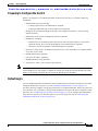
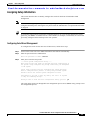
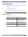
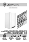
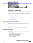
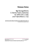
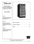
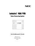
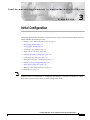
Se n d d o c u m e n t a t i o n c o m m e n t s t o m d s f e e d b a ck - d o c @ c i s c o . c o m
C H A P T E R
3
Initial Configuration
This chapter describes how to initially configure switches so they can be accessed by other devices. This
chapter includes the following sections:
Note
•
Starting a Cisco MDS 9020 Fabric Switch, page 3-2
•
Initial Setup Routine, page 3-2
•
Accessing the Switch, page 3-9
•
Assigning a Switch Name, page 3-10
•
Where Do You Go Next?, page 3-10
•
Verifying the Status of the Switch, page 3-10
•
Configuring Date and Time, page 3-11
•
Management Interface Configuration, page 3-13
•
Default Gateway Configuration, page 3-15
•
Telnet Server Connection, page 3-16
•
Working with Configuration Files, page 3-16
•
Deleting Files, page 3-21
No configuration is needed on the Cisco MDS 9020 Fabric Switch for interoperability with Brocade and
McData switches. For information on configuring these third party switches refer to the Cisco MDS
9000 Family Switch-to-Switch Interoperability Configuration Guide.
Cisco MDS 9020 Fabric Switch Configuration Guide and Command Reference
OL-6988-02
3-1
Chapter 3
Initial Configuration
Starting a Cisco MDS 9020 Fabric Switch
Se n d d o c u m e n t a t i o n c o m m e n t s t o m d s f e e d b a ck - d o c @ c i s c o . c o m
Starting a Cisco MDS 9020 Fabric Switch
The following procedure is a review of the tasks you should have completed during hardware
installation, including starting up the switch. These tasks must be completed before you can configure
the switch.
Before you can configure a switch, follow these steps:
Step 1
Verify the following physical connections for the new Cisco MDS 9020 Fabric Switch:
•
The console port is physically connected to a computer terminal (or terminal server).
•
The management 10/100 Ethernet port (mgmt0) is connected to an external hub, switch, or router.
Refer to the Cisco MDS 9020 Fabric Switch Hardware Installation Guide for more information.
Tip
Step 2
Step 3
Save the host ID information for future use (for example, to enable licensed features). The host
ID information is provided in the Proof of Purchase document that accompanies the switch.
Verify that the default console port parameters are identical to those of the computer terminal (or
terminal server) attached to the switch console port:
•
9600 baud
•
8 data bits
•
1 stop bit
•
No parity
Power on the switch. The switch boots automatically and the switch# prompt appears in your terminal
window.
Initial Setup Routine
The first time that you access a Cisco MDS 9020 Fabric Switch, it runs a setup program that prompts
you for the IP address and other configuration information necessary for the switch to communicate over
the Ethernet interface. This information is required to configure and manage the switch.
Note
The IP address can be configured from the CLI only. When you power up the switch for the first time,
assign the IP address. After you perform this step, the Cisco Fabric Manager can reach the switch
through the Ethernet port.
Cisco MDS 9020 Fabric Switch Configuration Guide and Command Reference
3-2
OL-6988-02
Chapter 3
Initial Configuration
Initial Setup Routine
Se n d d o c u m e n t a t i o n c o m m e n t s t o m d s f e e d b a ck - d o c @ c i s c o . c o m
Preparing to Configure the Switch
Before you configure a Cisco MDS 9020 Fabric Switch for the first time, you need the following
information:
•
Administrator password, including:
– Creating a password for the administrator (required).
– Creating an additional login account and password (optional).
•
IP address for the switch management interface. The management interface is an out-of-band
Ethernet interface.
•
Subnet mask for the switch's management interface (optional).
•
IP addresses, including:
– Destination prefix, destination prefix subnet mask, and next hop IP address, if you want to
enable IP routing. Also, provide the IP address of the default network (optional).
– Otherwise, provide an IP address of the default gateway (optional).
Note
•
SSH service on the switch—To enable this optional service, select the SSH key (rsa) and the number
of key bits (768 to 2048).
•
Default domain name (optional).
•
NTP server IP address (optional).
•
SNMP community string (optional).
•
Switch name—This is your switch prompt (optional).
Be sure to configure the IP route, the IP default network address, and the IP default gateway address to
enable SNMP access. If IP routing is enabled, the switch uses the IP route and the default network IP
address. If IP routing is disabled, the switch uses the default gateway IP address.
Default Login
The Cisco MDS 9020 Fabric Switch has the network administrator as a default user (admin). You cannot
change the default user at any time. (See the “Role-Based Authorization” section on page 9-5.)
You must explicitly configure a strong password for the Cisco MDS 9020 Fabric Switch. If a password
is trivial (short, easy-to-decipher), your password configuration is rejected. Be sure to configure a strong
password. (See “Configuring User Accounts” section on page 9-6.) If you configure and subsequently
forget this new password, you have the option to recover this password. (See the “Recovering the
Administrator Password” section on page 9-10.)
Cisco MDS 9020 Fabric Switch Configuration Guide and Command Reference
OL-6988-02
3-3
Chapter 3
Initial Configuration
Initial Setup Routine
Se n d d o c u m e n t a t i o n c o m m e n t s t o m d s f e e d b a ck - d o c @ c i s c o . c o m
Setup Options
The setup scenario differs based on the subnet to which you are adding the new switch. You must
configure a Cisco MDS 9020 Fabric Switch with an IP address to enable management connections from
outside of the switch. Figure 3-1 shows a switch that is managed out-of-band over a connection to the
network through an Ethernet port.
Figure 3-1
Management Access to Switches
Router
Console
connection
Out of band
management
subnetwork
IP
network
IP address
172.16.1.1
Telnet or
CLI
SSH
Switch 2
DNS server
mgmt 0
(IP address:
172.16.1.2)
GUI
Management LAN
(Ethernet connection)
79936
SNMP
Cisco MDS 9020 Fabric Switch Configuration Guide and Command Reference
3-4
OL-6988-02
Chapter 3
Initial Configuration
Initial Setup Routine
Se n d d o c u m e n t a t i o n c o m m e n t s t o m d s f e e d b a ck - d o c @ c i s c o . c o m
Assigning Setup Information
This section describes how to initially configure the switch for both out-of-band and in-band
management.
Note
Press Ctrl-C at any prompt to skip the remaining configuration options and proceed with what is
configured until that point. Entering the new password for the administrator is a requirement and cannot
be skipped.
Tip
If you do not wish to answer a previously configured question, or if you wish to skip answers to any
questions, press Enter. If a default answer is not available (for example, switch name), the switch uses
previously configured value and skips to the next question.
Configuring Out-of-Band Management
To configure the switch for first time out-of-band access, follow these steps:
Step 1
Power on the switch. The Cisco MDS 9020 Fabric Switch boots automatically.
Step 2
Enter the password for the administrator.
Enter the password for admin: admin123
Step 3
Enter yes to enter the setup mode.
---- Basic System Configuration Dialog ---This setup utility will guide you through the basic configuration of
the system. Setup configures only enough connectivity for management
of the system.
*Note: setup is mainly used for configuring the system initially,
when no configuration is present. So setup always assumes system
defaults and not the current system configuration values.
Press Enter if you want to skip any dialog. Use ctrl-c at anytime
to skip all remaining dialogs.
Would you like to enter the basic configuration dialog (yes/no): yes
The setup utility guides you through the basic configuration process. Press Ctrl-C at any prompt to end
the configuration process.
Cisco MDS 9020 Fabric Switch Configuration Guide and Command Reference
OL-6988-02
3-5
Chapter 3
Initial Configuration
Initial Setup Routine
Se n d d o c u m e n t a t i o n c o m m e n t s t o m d s f e e d b a ck - d o c @ c i s c o . c o m
Step 4
Enter yes (no is the default) to create additional accounts.
Note
Only the admin user name can create or modify user accounts.
Create another login account (yes/no) [n]: yes
While configuring your initial setup, you can create an additional user account (in the network-admin
role) besides the administrator’s account. See the “Role-Based Authorization” section on page 9-5 for
information on default roles and permissions.
a.
Enter the user login ID.
Enter the user login ID: user_name
b.
Enter the user password.
Enter the password for user_name: user-password
Confirm the password for user_name: user-password
c.
Enter the user role.
Enter the user role [network-operator]:network_admin
Step 5
Enter yes (no is the default) to configure the read-only or read-write SNMP community string.
Configure read-only SNMP community string (yes/no) [n]: yes
a.
Enter the SNMP community string.
SNMP community string: snmp_community
Step 6
Enter a name for the switch.
Note
The switch name is limited to 32 alphanumeric characters.
Enter the switch name: switch_name
Step 7
Enter yes (yes is the default) to configure out-of-band management.
Continue with Out-of-band (mgmt0) management configuration? [yes/no]: yes
a.
Enter the mgmt0 IP address.
Mgmt0 IP address: ip_address
b.
Enter the mgmt0 subnet mask.
Mgmt0 IP netmask: subnet_mask
Step 8
Enter yes (yes is the default) to configure the default gateway (recommended).
Configure the default-gateway: (yes/no) [y]: yes
a.
Enter the default gateway IP address.
IP address of the default-gateway: default_gateway
Step 9
Enter yes (yes is the default) to enable Telnet service.
Enable the telnet service? (yes/no) [y]: yes
Cisco MDS 9020 Fabric Switch Configuration Guide and Command Reference
3-6
OL-6988-02
Chapter 3
Initial Configuration
Initial Setup Routine
Se n d d o c u m e n t a t i o n c o m m e n t s t o m d s f e e d b a ck - d o c @ c i s c o . c o m
Step 10
Enter no (no is the default) to disable the SSH service.
Enabled SSH service? (yes/no) [n]: no
Step 11
Enter no (no is the default) to not configure the NTP server.
Configure NTP server? (yes/no) [n]: no
Step 12
Enter noshut (shut is the default) to configure the default switchport interface to the noshut state.
Configure default switchport interface state (shut/noshut) [shut]: noshut
Step 13
Enter deny (deny is the default) to deny a default zone policy configuration.
Configure default zone policy (permit/deny) [deny]: deny
Deny prevents traffic flow to all members of the default zone.
Step 14
You see the new configuration. Review and edit the configuration that you have just entered. Enter no
(no is the default) if you are satisfied with the configuration.
The following configuration will be applied:
username admin password admin_pass role network-admin
switchname switch
interface mgmt0
ip address ip_address subnet_mask
ip default-gateway 10.0.0.254
telnet server enable
no ssh server enable
no system default switchport shutdown
no zone default-zone permit
Would you like to edit the configuration? (yes/no) [n]: no
Step 15
Enter yes (yes is default) to use and save this configuration:
Use this configuration and save it? (yes/no) [y]: yes
Caution
If you do not save the configuration at this point, none of your changes are updated the next
time the switch is rebooted. Type yes to save the new configuration and ensure that the system
images are also automatically configured. (See Chapter 4, “Software Images”.)
Cisco MDS 9020 Fabric Switch Configuration Guide and Command Reference
OL-6988-02
3-7
Chapter 3
Initial Configuration
Initial Setup Routine
Se n d d o c u m e n t a t i o n c o m m e n t s t o m d s f e e d b a ck - d o c @ c i s c o . c o m
Using the setup Command
To make changes to the initial configuration at a later time, you can enter the setup command in EXEC
mode.
Note
The setup utility is mainly used for the initial configuration when no configuration is present. The setup
utility assumes system defaults and not the current system configuration values.
switch# setup
---- Basic System Configuration Dialog ---This setup utility will guide you through the basic configuration of
the system. Setup configures only enough connectivity for management
of the system.
*Note: setup always assumes a predefined defaults irrespective
of the current system configuration when invoked from CLI.
Press Enter in case you want to skip any dialog. Use ctrl-c at anytime
to skip away remaining dialogs.
Would you like to enter the basic configuration dialog (yes/no): yes
The setup utility guides you through the basic configuration process.
Cisco MDS 9020 Fabric Switch Configuration Guide and Command Reference
3-8
OL-6988-02
Chapter 3
Initial Configuration
Accessing the Switch
Se n d d o c u m e n t a t i o n c o m m e n t s t o m d s f e e d b a ck - d o c @ c i s c o . c o m
Accessing the Switch
After initial configuration, you can access the switch in the following ways:
•
Serial console access—You can use a serial port connection to access the CLI.
•
Out-of-band (10/100BASE-T Ethernet) access—You can use Telnet or SSH to access a Cisco MDS
9020 Fabric Switch or use SNMP to connect to Cisco Fabric Manager.
Note
To use Cisco Fabric Manager, refer to the Cisco MDS 9000 Family Fabric Manager
Configuration Guide.
Figure 3-2 illustrates serial console access and out-of-band access.
Figure 3-2
Switch Access Options
Router
Console
connection
Out of band
management
subnetwork
IP
network
IP address
172.16.1.1
Telnet or
CLI
SSH
Switch 2
DNS server
mgmt 0
(IP address:
172.16.1.2)
GUI
Management LAN
(Ethernet connection)
79936
SNMP
Cisco MDS 9020 Fabric Switch Configuration Guide and Command Reference
OL-6988-02
3-9
Chapter 3
Initial Configuration
Assigning a Switch Name
Se n d d o c u m e n t a t i o n c o m m e n t s t o m d s f e e d b a ck - d o c @ c i s c o . c o m
Assigning a Switch Name
Each switch in the fabric requires a unique name. You can assign names to easily identify the switch by
its physical location, its SAN association, or the organization to which it is deployed. The assigned name
is displayed in the command-line prompt. The switch name is limited to 32 alphanumeric characters.
Note
This guide refers to the Cisco MDS 9020 Fabric Switch as switch, and it uses the switch# prompt.
To change the name of the switch, perform this task:
Command
Purpose
Step 1
switch# config t
Enters configuration mode.
Step 2
switch(config)# switchname myswitch1
myswitch1(config)#
Changes the switch name prompt as specified.
Step 3
myswitch1(config)# no switchname
switch(config)#
Reverts the switch name prompt to its default (switch#).
Where Do You Go Next?
After reviewing the default configuration, you can change it or perform other configuration or
management tasks. The initial setup can be performed at the CLI only. However, you can continue to
configure other software features or access the switch after initial configuration by using either the CLI
or the Device Manager and Fabric Manager applications.
To use the Cisco Fabric Manager, refer to the Cisco MDS 9000 Family Fabric Manager Configuration
Guide.
Verifying the Status of the Switch
Before you begin configuring the switch, you need to ensure that the switch is functioning as designed.
To verify the status of a switch at any time, enter the show module command in EXEC mode. A sample
output of the show module command follows:
switch# show module
Mod Ports Module-Type
Model
Status
--- ----- ------------------------------- ------------------ -----------1
20
1/2/4 Gbps FC/Supervisor
DS-C9020-20K9
active *
Mod
--1
Sw
-----------2.1(2)
Hw
World-Wide-Name (WWN)
------ -------------------------------------------------------- 10:00:00:0d:ec:19:cb:01
Mod
--1
MAC-Address
-------------------------------------00-c0-dd-03-d4-e4
Serial-Num
---------0426a07855
* this terminal session
If the status is OK or active, you can continue with your configuration.
Cisco MDS 9020 Fabric Switch Configuration Guide and Command Reference
3-10
OL-6988-02
Chapter 3
Initial Configuration
Configuring Date and Time
Se n d d o c u m e n t a t i o n c o m m e n t s t o m d s f e e d b a ck - d o c @ c i s c o . c o m
Configuring Date and Time
A Cisco MDS 9020 Fabric Switch uses Universal Coordinated Time (UTC), which is the same as
Greenwich Mean Time (GMT). To change the default time on the switch, enter the clock command from
EXEC mode.
switch# clock set <HH:MM:SS> <DD> <Month in words> <YYYY>
The following example sets the time on the switch:
switch# clock set 15:58:09 23 May 2005
Mon May 23 15:58:09 UTC 2005
Where HH represents hours in military format (15 for 3 p.m.), MM is minutes (58), SS is seconds (09),
DD is the date (23), Month is the month in words (May), and YYYY is the year (2005).
Note
The clock command changes are saved across system resets.
Configuring the Time Zone
You can specify a time zone for the switch.
To specify the local time without the daylight savings feature, perform this task:
Command
Purpose
Step 1
switch# config t
Enters configuration mode.
Step 2
switch(config)# clock timezone <timezone
name> <-23 to 23 hours offset from UTC time>
<0 to 50 minutes offset from UTC>
Sets the time zone with a specified name,
specified hours, and specified minutes.
Example:
switch(config)# clock timezone PST -8 0
This example sets the time zone to Pacific
Standard Time (PST) and offsets the UTC time by
negative eight hours and 0 minutes.
Step 3
switch(config)# exit
switch#
Returns to EXEC mode.
Step 4
switch# show clock
Verifies the time zone configuration.
Step 5
switch# show run
Displays changes made to the time zone
configuration along with other configuration
information.
Cisco MDS 9020 Fabric Switch Configuration Guide and Command Reference
OL-6988-02
3-11
Chapter 3
Initial Configuration
Configuring Date and Time
Se n d d o c u m e n t a t i o n c o m m e n t s t o m d s f e e d b a ck - d o c @ c i s c o . c o m
Adjusting for Daylight Saving Time
Following U.S. standards, the switch can advance the clock one hour at 2:00 a.m. on the first Sunday in
April and move the clock back one hour at 2:00 a.m. on the last Sunday in October. You can also
explicitly specify the start and end dates and times, and you can specify whether or not the time
adjustment recurs every year.
To enable the daylight saving time clock adjustment according to the U.S. rules, perform this task:
Command
Purpose
Step 1
switch# config t
Enters configuration mode.
Step 2
switch(config)# clock timezone
timezone_name hour_offset_from_UTC
minute_offset_from_UTC
Offsets the time zone as specified.
Example:
switch(config)# clock timezone PST -8 0
Step 3
This example sets the Pacific standard offset time as
negative 8 hours and 0 minutes.
switch(config)# no clock timezone
Disables the time zone adjustment feature.
switch(config)# clock summer-time
daylight_timezone_name start_week
start_day start_month start_time end_week
end_day end_month end_time
daylight_offset_inminutes
Sets the daylight savings time for a specified time
zone.
Follow this example:
switch(config)# clock summer-time PDT 1
Sun Apr 02:00 5 Sun Oct 02:00 60
switch(config)#
The start and end values are as follows:
•
Week ranging from 1 through 5
•
Day ranging from Sunday through Saturday
•
Month ranging from January through
December
The daylight offset ranges from 1 through 1440
minutes, which are added to the start time and
deleted time from the end time.
This example adjusts the daylight savings time for
the Pacific daylight time by 60 minutes, starting the
first Sunday in April at 2 a.m. and ending the last
Sunday in October at 2 a.m.
switch(config)# no clock summer-time
Disables the daylight saving time adjustment
feature.
Step 4
switch(config)# exit
switch#
Returns to EXEC mode.
Step 5
switch# show clock
Verifies the time zone configuration.
Cisco MDS 9020 Fabric Switch Configuration Guide and Command Reference
3-12
OL-6988-02
Chapter 3
Initial Configuration
Management Interface Configuration
Se n d d o c u m e n t a t i o n c o m m e n t s t o m d s f e e d b a ck - d o c @ c i s c o . c o m
NTP Configuration
A Network Time Protocol (NTP) server provides a precise time source (radio clock or atomic clock) to
synchronize the system clocks of network devices. NTP is transported over User Datagram Protocol
UDP/IP. All NTP communications use UTC. An NTP server receives its time from a reference time
source, such as a radio clock or atomic clock, attached to the time. NTP distributes this time across the
network.
In a large enterprise network, having one time standard for all network devices is critical for management
reporting and event logging functions when trying to correlate interacting events logged across multiple
devices. Many enterprise customers with extremely mission-critical networks maintain their own
stratum-1 NTP source.
Time synchronization happens when several frames are exchanged between clients and servers. The
switches in client mode know the address of one or more NTP servers. The servers act as the time source
and receive client synchronization requests.
To configure NTP in a server association, perform this task:
Command
Purpose
Step 1
switch# config t
Enters configuration mode.
Step 2
switch(config)# ntp server 10.10.10.10
switch(config)#
Forms a server association with a server.
Step 3
switch(config)# exit
switch#
Returns to EXEC mode.
Step 4
switch# copy running-config startup-config
Saves your configuration changes to nonvolatile
memory.
Tip
This is one instance where you can save
the configuration as a result of an NTP
configuration change. You can enter this
command at any time.
Management Interface Configuration
A single IP address is used to manage the switch. The switch management (mgmt0) interface uses this
IP address. The management interface on the switch allows multiple, simultaneous Telnet or SNMP
sessions. You can remotely configure the switch through the management interface, but first you must
configure some IP parameters (IP address, subnet mask) so that the switch is reachable. You can
manually configure the management interface from the CLI.
The management port (mgmt0) is autosensing and operates in full duplex mode at a speed of 10/100
Mbps. The speed and mode cannot be configured.
Note
Before you begin to configure the management interface manually, obtain the switch’s IP address and IP
subnet mask. Also make sure the console cable is connected to the console port.
Cisco MDS 9020 Fabric Switch Configuration Guide and Command Reference
OL-6988-02
3-13
Chapter 3
Initial Configuration
Management Interface Configuration
Se n d d o c u m e n t a t i o n c o m m e n t s t o m d s f e e d b a ck - d o c @ c i s c o . c o m
Obtaining Remote Management Access
In some cases, a switch interface might be administratively shut down. You can check the status of an
interface at any time by using the show interface mgmt 0 command.
To obtain remote management access, perform this task:
Command
Command
Step 1
switch# config terminal
switch(config)#
Enters configuration mode. You can also abbreviate
the command to config t.
Step 2
switch(config)# interface mgmt 0
Enters the interface configuration mode on the
specified interface (mgmt0).
You can use the management Ethernet interface on
the switch to configure the management interface.
Step 3
switch(config)# ip address 10.1.1.0
255.255.255.0
Enters the IP address and IP subnet mask for the
interface specified in Step 2.
Step 4
switch(config-if)# no shutdown
Enables the interface.
Step 5
switch(config-if)# exit
Returns to configuration mode.
Step 6
switch(config)# ip default-gateway
10.1.1.1
Configures the default gateway address.
Using the force Option
When you try to shut down a management interface (mgmt0), a follow-up message confirms your action
before performing the operation. You can use the force option to bypass this confirmation. The following
example shuts down the interface without using the force option:
Caution
Do not shut down the mgmt0 port unless you have direct console access. If the management interface is
shutdown, a console connection is the only way to regain access to the switch.
switch# config t
switch(config)# interface mgmt 0
switch(config-if)# shutdown
Shutting down this interface will drop all telnet sessions.
Do you wish to continue (y/n)? y
The following example shuts down the interface using the force option:
switch# config t
switch(config)# interface mgmt 0
switch(config-if)# shutdown force
Note
You need to explicitly configure a default gateway to connect to the switch and send IP packets or add a
route for each subnet.
Cisco MDS 9020 Fabric Switch Configuration Guide and Command Reference
3-14
OL-6988-02
Chapter 3
Initial Configuration
Default Gateway Configuration
Se n d d o c u m e n t a t i o n c o m m e n t s t o m d s f e e d b a ck - d o c @ c i s c o . c o m
Default Gateway Configuration
The switch sends IP packets with unresolved destination IP addresses to the default gateway. Figure 3-3
shows the default gateway.
Figure 3-3
Default Gateway
Default
gateway
Console
connection
Router
IP
Network
IP Address
172.16.1.1
Telnet or
CLI
SSH
Switch 2
DNS server
mgmt 0
(IP address:
172.16.1.2)
GUI
SNMP
79937
Management LAN
(Ethernet connection)
Configuring the Default Gateway
To configure the IP address of the default gateway, follow these steps:
Command
Purpose
Step 1
switch# config t
Enters configuration mode.
Step 2
switch(config)# ip default-gateway 172.16.1.1
Configures the 172.16.1.1 IP address.
Cisco MDS 9020 Fabric Switch Configuration Guide and Command Reference
OL-6988-02
3-15
Chapter 3
Initial Configuration
Telnet Server Connection
Se n d d o c u m e n t a t i o n c o m m e n t s t o m d s f e e d b a ck - d o c @ c i s c o . c o m
Telnet Server Connection
The Telnet server is enabled by default on a Cisco MDS 9020 Fabric Switch. If you require a secure SSH
connection, you need to disable the default Telnet connection and then enable the SSH connection. (See
the “Enabling SSH Service” section on page 9-9.)
Tip
A maximum of nine Telnet sessions are allowed on a Cisco MDS 9020 Fabric Switch.
Make sure the terminal is connected to the switch and that the switch and terminal are both powered on.
Disabling a Telnet Connection
To disable Telnet connections to the switch, perform this task:
Command
Purpose
Step 1
switch# config t
Enters configuration mode.
Step 2
switch(config)# no telnet server enable
updated
Disables the Telnet server.
Working with Configuration Files
Configuration files can contain some or all of the commands needed to configure one or more switches.
For example, you might want to download the same configuration file to several switches that have the
same hardware configuration so that they have identical module and port configurations.
This section describes how to work with configuration files and has the following topics:
•
Displaying Configuration Files, page 3-17
•
Downloading Configuration Files to the Switch, page 3-19
•
Saving the Configuration, page 3-20
•
Copying Files, page 3-20
•
Backing Up the Current Configuration, page 3-20
•
Rolling Back to a Previous Configuration, page 3-21
Cisco MDS 9020 Fabric Switch Configuration Guide and Command Reference
3-16
OL-6988-02
Chapter 3
Initial Configuration
Working with Configuration Files
Se n d d o c u m e n t a t i o n c o m m e n t s t o m d s f e e d b a ck - d o c @ c i s c o . c o m
Displaying Configuration Files
Use the show running-config command to view the running configuration file.
switch# show running-config
ip default-gateway 10.20.83.1
logging level fcdomain 2
logging level fspf 2
logging level fcns 2
logging level fcs 2
logging level port 2
logging level zone 2
logging level auth 2
logging level ipconf 2
logging level module 2
logging level ntp 2
logging level sysmgr 2
no snmp-server contact
no snmp-server location
zone name asdfa
zoneset name dave
interface mgmt0
ip address 10.20.83.122 255.255.255.0
interface fc1/1
interface fc1/2
interface fc1/3
interface fc1/4
interface fc1/5
interface fc1/6
interface fc1/7
interface fc1/8
interface fc1/9
interface fc1/10
interface fc1/11
interface fc1/12
interface fc1/13
interface fc1/14
interface fc1/15
interface fc1/16
interface fc1/17
interface fc1/18
interface fc1/19
interface fc1/20
Use the show startup-config command to view the startup configuration file.
switch# show startup-config
interface fc1/1
no shutdown
Auto
interface fc1/2
no shutdown
Auto
interface fc1/3
no shutdown
Fx
interface fc1/4
no shutdown
Auto
Cisco MDS 9020 Fabric Switch Configuration Guide and Command Reference
OL-6988-02
3-17
Chapter 3
Initial Configuration
Working with Configuration Files
Se n d d o c u m e n t a t i o n c o m m e n t s t o m d s f e e d b a ck - d o c @ c i s c o . c o m
interface fc1/5
no shutdown
Auto
interface fc1/6
no shutdown
Auto
interface fc1/7
no shutdown
Auto
interface fc1/8
no shutdown
Auto
interface fc1/9
no shutdown
Auto
interface fc1/10
no shutdown
Auto
interface fc1/11
no shutdown
Auto
interface fc1/12
no shutdown
Auto
interface fc1/13
no shutdown
Auto
interface fc1/14
no shutdown
Auto
interface fc1/15
no shutdown
Auto
interface fc1/16
no shutdown
Auto
interface fc1/17
no shutdown
Auto
interface fc1/18
no shutdown
Auto
interface fc1/19
no shutdown
Auto
interface fc1/20
no shutdown
Auto
Cisco MDS 9020 Fabric Switch Configuration Guide and Command Reference
3-18
OL-6988-02
Chapter 3
Initial Configuration
Working with Configuration Files
Se n d d o c u m e n t a t i o n c o m m e n t s t o m d s f e e d b a ck - d o c @ c i s c o . c o m
Downloading Configuration Files to the Switch
You can configure a Cisco MDS 9020 Fabric Switch by using configuration files that you create or
download from another switch. Before you begin downloading a configuration file using a remote server,
do the following:
•
Ensure that the configuration file to be downloaded is in the correct directory on the remote server.
•
Ensure that the permissions on the file are set correctly. Permissions on the file should be set to
world-read.
•
Ensure that the switch has a route to the remote server. The switch and the remote server must be in
the same subnetwork if you do not have a router or default gateway to route traffic between subnets.
Check connectivity to the remote server using the ping command.
From a Remote Server
To configure a Cisco MDS 9020 Fabric Switch using a configuration file downloaded from a remote
server using TFTP or FTP, follow these steps:
Step 1
Log in to the switch through the console port or through a Telnet or SSH session.
Step 2
Configure the switch using the configuration file downloaded from the remote server using the
copy <scheme> :// <server address> running-config command, where scheme is TFTP or FTP.
The configuration file downloads and the commands are executed as the file is parsed line by line.
Saving Configuration Files to an External Device
You can save a configuration file stored on internal storage to a remote server.
To a Remote Server
To save a configuration file to a remote server such as FTP, follow these steps:
Step 1
Log into the switch through the console port or through a Telnet or SSH session.
Step 2
Save the configuration using the copy running-config <scheme> :// <server address> command, where
scheme is FTP.
Step 3
Specify the IP address or host name of the remote server and the name of the file to download.
The configuration file is saved to the remote server.
Use the following command to save a running configuration file to a remote server:
switch# copy running-config <scheme>://<server address>
Use the following command to save a startup configuration file to a remote server:
switch# copy bootflash:startup-config <scheme>://<server address>
Cisco MDS 9020 Fabric Switch Configuration Guide and Command Reference
OL-6988-02
3-19
Chapter 3
Initial Configuration
Working with Configuration Files
Se n d d o c u m e n t a t i o n c o m m e n t s t o m d s f e e d b a ck - d o c @ c i s c o . c o m
Saving the Configuration
After you have created a running configuration in system memory, you can save it to the startup
configuration in the bootflash: file system using the following copy command:
switch# copy running-config bootflash:startup-config
The copy running-config startup-config command is an alias to the previous command and is used
frequently throughout this guide.
Copying Files
The syntax for the copy command follows and is explained in Table 3-1.
switch# copy <scheme>://<server>/<file name> <scheme>://<server>/<file name>
Table 3-1
copy Command Syntax
Scheme
Server
File Name
volatile
—
User-specified
bootflash
—
User-specified
tftp
IP address or DNS name
User-specified
ftp
•
This example shows how to copy a running configuration to the bootflash: file system:
switch# copy running-config bootflash:my-config
•
This example shows how to overwrite the contents of an existing configuration in the nonvolatile file
system:
switch# copy bootflash:my-config bootflash:startup-config
Backing Up the Current Configuration
Before installing or migrating to any software configuration, back up the startup configuration.
•
This example shows how to back up the startup configuration copy in the bootflash: file system
(ASCII file):
switch# copy startup-config bootflash:my-config
•
This example shows how to back up the startup configuration to the TFTP server (ASCII file):
switch# copy startup-config tftp://172.16.10.100/my-config
•
This example shows how to back up the running configuration to the bootflash: file system (ASCII
file):
switch# copy running-config bootflash:my-config
Cisco MDS 9020 Fabric Switch Configuration Guide and Command Reference
3-20
OL-6988-02
Chapter 3
Initial Configuration
Deleting Files
Se n d d o c u m e n t a t i o n c o m m e n t s t o m d s f e e d b a ck - d o c @ c i s c o . c o m
Rolling Back to a Previous Configuration
All switch configurations reside in the internal bootflash: file system. If your internal bootflash: file
system is corrupted, you could potentially lose your configuration. Save and back up your configuration
file periodically.
•
This example shows how to roll back to a snapshot copy of a previously saved running configuration
(binary file):
switch# copy bootflash:snapshot-config bootflash:startup-config
Note
•
You can enter a rollback command only when a snapshot is already created. Otherwise, you
will receive the No snapshot-config found error message.
This example shows how to roll back to a configuration copy that was previously saved in the
bootflash: file system (ASCII file):
switch# copy bootflash:my-config startup-config
Note
Each time a copy running-config startup-config command is entered, a binary file is created and the
ASCII file is updated. A valid binary configuration file reduces the overall boot time significantly. A
binary file cannot be uploaded, but its contents can be used to overwrite the existing startup
configuration. The write erase command clears the binary file.
Deleting Files
Assuming you are already in the bootflash: file system, use the delete command to delete a file from the
bootflash: file system:
switch# delete dns_config.cfg
Cisco MDS 9020 Fabric Switch Configuration Guide and Command Reference
OL-6988-02
3-21
Chapter 3
Initial Configuration
Deleting Files
Se n d d o c u m e n t a t i o n c o m m e n t s t o m d s f e e d b a ck - d o c @ c i s c o . c o m
Cisco MDS 9020 Fabric Switch Configuration Guide and Command Reference
3-22
OL-6988-02