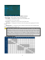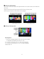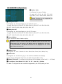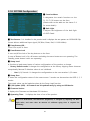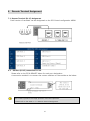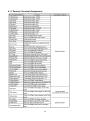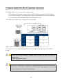
1
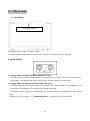
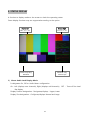
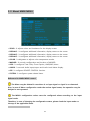
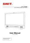
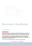
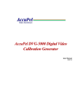
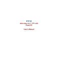
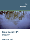
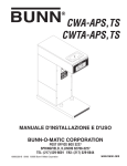
Operating Instructions User Manual 25” OLED Monitor (Multi Format) Model : TOM Version 1.0 May 2013 Safety Instructions To help avoid damaging your monitor, connect only one power (AC or DC) in operation. Rough handling of product may cause physical damage or malfunction. Never insert anything metallic into the monitor openings. Doing so may create the danger of electric shock. To avoid electric shock, never touch the inside of the monitor. Only a qualified should open the monitor’s case. Openings in the monitor cabinet are provided for ventilation. To prevent overheating, these openings should not be blocked or covered. Put your monitor in a location with low humidity and a minimum of dust. Avoid places like damp basement or dusty hallways. Place the monitor on a solid surface and treat it carefully. The screen is made of glass and can be damaged if dropped or sharply hit. Do not attempt to remove the back cover, as you will be exposed to a shock hazard. The back cover should only be removed by qualified service personnel. Unplug the monitor power before you connect external devices to the monitor. If your monitor does not operate normally, or if there are any unusual sounds or smells coning from it, unplug it immediately and contact us. Please do not disassemble the monitor. No service will be provided in that case. Displaying fixed picture for a long time may cause an afterimage or dead spots. To recover OLED pixels, display whole white picture on screen for a hour or two and pixels will be recovered. No service will be provided for user’s own color calibration. 2 Thank you for purchasing our product. Please read instruction manual before installation or use. Please contact our service center or sales team if any problem occurs. Table of Contents 1. Product Outline• • • • • • • • • • • • • • • • • • • • • • • • • • • • • • • • • • 5 2. Product Functions and Features • • • • • • • • • • • • • • • • • • • • • • • • • • • • • 5 3. Function descriptions • • • • • • • • • • • • • • • • • • • • • • • • • • • • • • • • • • • • • • 6 3 - 1. Front Panel • • • • • • • • • • • • • • • • • • • • • • • • • • • • 6 3 - 2 . Re a r Pa n e l • • • • • • • • • • • • • • • • • • • • • • • • • • 8 3 - 3 . Ta l l y & A u d i o • • • • • • • • • • • • • • • • • • • • • • • • • • 1 0 3-4. Front F1, F2, F3, F4 Function Designation • • • • • • • • • • • • • • • • • • • • 11 4. STATUS DISPL AY • • • • • • • • • • • • • • • • • • • • • • • • • • • • • 12 5. OSD Menu Adjustment• • • • • • • • • • • • • • • • • • • • • • • •• • • • • • 13 5-1. MENU configuration method • • • • • • • • • • • • • • • • • • • • • • • • • • 13 5-2. About Main MENU • • • • • • • • • • • • • • • • • • • • • • • • • • • 14 5-3. VIDEO Configuration • • • • • • • • • • • • • • • • • • • • • • • • • • 15 5-3-1. VGA COLOR Configuration • • • • • • • • • • • • • • • • • • • • • • • • • • 16 5-3-2. VGA DISPLAY Configuration • • • • • • • • • • • • • • • • • • • • • • • • • • 17 5-4. DISPL AY 1,2,3 Configuration • • • • • • • • • • • • • • • • • • • • • • 18 5-5. COLOR Configuration • • • • • • • • • • • • • • • • • • • • • • • • • • 26 5-6. MARKER Configuration • • • • • • • • • • • • • • • • • • • • • • • • • 27 5-7. OSD Configuration • • • • • • • • • • • • • • • • • • • • • • • • • • • • 28 5-8. AUDIO Configuration • • • • • • • • • • • • • • • • • • • • • • • • • 33 5-9. GPI Configuration • • • • • • • • • • • • • • • • • • • • • • • • 35 5-10. SYSTEM Configuration • • • • • • • • • • • • • • • • • • • • • • • • 36 6 . Re m o t e Te r m i n a l A s s i g n m e n t • • • • • • • • • • • • • • • • • • • • 37 6-1. Remote Terminal (RJ-45) Assignment • • • • • • • • • • • • • • • • • • • • 37 6-2. GPI Port (RJ-45) Connection for Use • • • • • • • • • • • • • • • • • • • • 37 6-3. Remote Terminal Assignment • • • • • • • • • • • • • • • • • • • • 38 7. Program Update Port (RJ-11) operating instructions • • • • • • • • • • • • • • • 39 7-1. Numbers of Monitors Connection Control Method • • • • • • • • • • • 40 8. Program Update Por t (USB) operation instructions • • • • • • • • • • • • • 41 9. List of Compatible Signal Formats (Video Signal) • • • • • • • • • • • • • • 42 9 - 1 . C o m p u t e r S i g n a l s ( P C - RG B / D V I ) • • • • • • • • • • • • • • • • • 43 10. Specifications • • • • • • • • • • • • • • • • • • • • • • • • • • • • • • 44 11. Product Appearance (Dimensions) • • • • • • • • • • • • • • • • • • • • • • 47 3 1 2 . Tr o u b l e s h o o t i n g • • • • • • • • • • • • • • • • • • • • • • • • • • • 4 9 13. Maintenance • • • • • • • • • • • • • • • • • • • • • • • • • • • • 51 14. Product change • • • • • • • • • • • • • • • • • • • • • • • • • • • • • • • • 4 52 1. Product Overview Supporting video signals from standard HD/SD-SDI signals, 2ch HD-SDI input and Composite/ YC/ YPbPr/ RGB/ DVI/ PC-RGB/ HDMI(HDCP) signals, this OLED panel multi format monitor is designed for broadcast monitoring that requires high quality and reliability. 2. Product Functions and Features • 12-bit Signal Processor • 3D-LUT • Gamma Selection • USB Memory Update • Waveform • Vector scope Display • Focus Assistance(Except ANALOG CH) • False Color(Except ANALOG CH) • Closed Caption (CEA-608/708) • Gen-lock(video synchronization) • Time Code(Except SDI 3G Level B) • 8~16ch Audio Level Meter • Exposure Range Check • UMD/IMD Mode • AFD & V-CHIP(SDI Only) • Various Markers • H/V Delay • Pixel-to-Pixel View • Zero/Under/Over Scan • Fast Motion Mode • Freeze Frame • Blending, PaP, PiP • R/G/B/W, 100%/75% Color Bar, RP219 Internal Patterns • Rack & VESA Mount (Option) Please refer to the Specification Sheet per products for options. 5 3. Function Descriptions 3-1. Front Panel ⑬ ⑭ 16 ① ① ② ③ ④ ⑤ ⑥ ⑦ ⑧ ⑨ ⑩ ⑪ ⑫ ⑮ STANDBY A power on/off button. It operates on/off when the button is pressed for about one second. ② HDMI / DVI INPUT SELECT For HDMI / DVI input selection. It toggle converts to HDMI, DVI modes whenever the ③ Analog INPUT SELECT For Analog input selection. It is converted to CVBS1,2,3, YC modes, Ypbpr, RGB, VGA whenever the button is entered. ④ W-FORM/VECTOR In case this button is pressed, it displays the Video waveform regarding the input signal as Wave form or Vector Scope types. It toggle converts to each mode whenever the button is pressed. ⑤ Audio Level Turns audio level meters on. ⑥ MARKER A configured MARKER is displayed on the screen ⑦ FUNCTION (F1, F2, F3, F4) A Function button is a function setup by the user among many functions on the SYSTEM MENU. ⑧ ENTER 1) It is operated as an Enter key during the OSD MENU configuration. Save the configured values and Move to the next step. 6 2) If it’s not under the MENU adjustment status, a OSD LOGO window is displayed to display source information of input selection currently when the STATUS button is pressed ⑨ SCAN For converting the display status of the screen for Zero Scan, Under Scan, Over Scan, Zoom Scan modes. It toggle converts to each mode whenever the button is pressed. ⑩ H/V Delay A function to check information on areas excluding the Active area from any input signals. It is converted to H Delay, V Delay, H/V Delay, Off modes. ⑪ RGB Gray Displays Red, Green, Blue, or Gray color only mode. The switching order is Red -> Green -> Blue -> Gray -> Off as pressing the button. ⑫ Focus Displays focus area of the image. Focus sensitivity is adjustable on DISPLAY3 / Focus Assist Level menu item. ⑬ Video Attribute Adjusts Brightness, Contrast, Chroma, or Audio Volume. The item switches to the next one by pressing the knob. ⑭ MENU OSD MENU is activated when this button is selected. For MENU setup operation ⑮ False Color Displays False Colors of the image, usually to check exposure levels of the image. SDI 1, SDI 2 INPUT SELECT 16 For SDI CH1, CH2 input selection. A separate OSD LOGO window is displayed. ! 3G SDI Level B Mode and Dual SDI Mode are converted by the Menu setup. 7 3-2. Rear Panel ⑩ ⑪ ⑫ ⑬ ② ③ ④ ⑤ ⑭ ⑥ ① ⑧ ⑨ ① AC INPUT Terminal For AC (100V~230V) power supply. ② SDI 1 , SDI 2 Input Terminal A HD/SD-SDI signal input terminal. A SMPTE standard method and SDI signal input that includes Audio signal is available. ③ LOOPOUT Terminal Active Loop signal output terminals for each SDI-1 and SDI-2. ④ Composite / Component Input For CVBS1,2,3, YUV(Y,Pb,Pr) and R,G,B input ⑤ Composite / Component Loop Out A LOOP signal output terminal for Composite and Component. ⑥ External Sync Input For External Sync input. ⑦ External Sync Loop Out 8 ⑦ A LOOP signal output terminal for External Sync. ⑧ DVI-I For digital signal input. ⑨ HDMI For digital signal input. ⑩ ETHERNET (RJ-45 Jack) The port for controlling monitor remotely through network. ⑪ UPDATE Port (RJ-11 Jack) A Serial communication terminal. It changes the operating program of the body or controls the monitor. Please refer to the clause 7. 7. Program Update Port operating instructions. ⑫ REMOTE Port ,RJ-45 Jack –Through (RJ-45) terminal -> Option For controlling the body from outside. It is a Make/Trig method terminal. Please refer to the clause 8. 8. Remote Terminal Assignment connecting method for more details. ⑬ USB Update Port For changing the operating program of the body using an USB. Please refer to the clause 7. 7. Program Update Port operating instructions for more details. ⑭ AUDIO IN/OUT A terminal for external Audio input and Embedded Audio signal display. Please refer to the clause 3-3. Audio input/output description ⑬ DVI-I For digital signal input. ⑭ HDMI For digital signal input. ⑮ PLD Update Port For updating PLD. Please check Power Cord, Power Voltage, Supply power for power input are suitable for the standard before use. 9 3-3. Tally & Audio 1) Tally Display Tally display window Tally displays Red, Green, Amber 3 colors. It can be displayed optionally by the contact input on the outside control terminal. 2) AUDIO IN/OUT ① Analog Audio L/R Input Terminal (Stereo Pin Jack) An Analog Audio external input terminal. It can display the Level on the screen by the Menu configuration, and display the sound through the speaker installed on the body. ② Analog Audio L/R Output Terminal (Stereo Pin Jack) A terminal displays the Audio signals. It can display 16CH Audio signal De-embedded on SDI by the Menu configuration or external input signal optionally. The Audio output signal is not adjusted by the Speaker Volume and displayed as the entered level. Please refer to the clause 6-5. Embedded Audio 10 configuration for more details. 3-4. Front F1, F2, F3, F4 Function Designation The function buttons of F1, F2, F3, F4 on the front can select below functions on the SYSTEM MENU configuration and designates then the applicable function can be used. Configurable Functions 1. PC SCAN Aspect/Fill 14. Caption Display On/Off 2. Aspect Native/16:9 15. Audio Display On/Off 3. Pixel to Pixel On/Off 16. Audio Mute On/Off 4. Anamorphic On/Off 17. H/V Delay On/Off 5. PaP On/Off 18. Freeze Main On/Off 6. PiP On/Off 19. Freeze sub On/Off 7. Blending On/Off 20. Front Button LED On/Off 8. Sync Mode On/Off 21. Video Loss Tally 9. 3G Mode On/Off 22. Video Loss Alarm 10. Dual Link On/Off 23. Exposure Range Check 11. Fast Mode On/Off 24. Focus Assist Display 12. Time Code Display On/Off 25. IMD/UMD Mode On/Off 13. False Color Display 26. RGB Gray Only On/Off Note H/V Delay function is supported on following modes only. 1) SDI-1, SDI-2 input 2) CVBS1, CVBS2 input 3) S-Video 4) YPbPr, RGB input 11 4. STATUS DISPLAY A function to display mode on the screen to check the operating status. Some display functions may not supported according to the option. Display Left Display Right CH-1, 3, 5 ~ 15 CH-2, 4, 6 ~ 16 Vector Scope 또는 Waveform 또는 Waveform Vector Scope 1) About Audio Level Display Mode It designates On, Off on Audio Menu configuration. On : Left (displays even channels), Right (displays odd channels), OFF Bar display. Display Position designation : Designates/displays Upper, Lower Display Size designation : Configures/displays Normal and Large 12 : Turns off the Level 2) About Waveform Monitor, Vector Scope Waveform monitor and Vector Scope can be turned On/Off by the WF/VS buttons on the front. Whenever the button is pressed, it operates as following : displays Waveform monitor -> displays Vector Scope -> displays both Waveform monitor and Vector Scope. The display location of Waveform monitor and Vector Scope are changeable on the DISPLAY2 MENU. The display locations are Left Top, Right Top, Left Bottom, Right Bottom. 3) About Time Code Display It designates On, Off and configures the location on the Display Menu configuration. Display Position designation: Designates/displays top and bottom of the center part. • Time Code Display function is supported on following input modes only. - SDI-1, SDI-2, 3G Level A Mode • Time Code is not displayed under the No signal input status even though the Time Code Display is set as On mode. 5. OSD Menu Control 5-1. MENU Configuration Method 1) Press the MENU button on the front, and OSD MENU initial screen is displayed. 2) Move to an item for adjusting by using the ADJUST button. Press the Knob or Enter button to select. Note) Under the MENU adjustment status, it functions as UP(CW) ▲ or DOWN(CCW) ▼ by the ADJUST Knob button adjustment. At this time, the ADJUST Knob is operated as the ENTER. 3) On the selected item, adjust it as desired by using UP ▲ / DOWN ▼ buttons. 4) Press the MENU button to save the selected value and it moves to the previous item. 5) Press the MENU button continuously then the OSD screen is terminated. 13 5-2. About MAIN MENU ▪ VIDEO : It adjusts colors and luminance for the display screen. ▪ DISPLAY1 : It configures additional information, display status on the screen. ▪ DISPLAY2 : It configures additional information, display status on the screen. ▪ DISPLAY3 : It configures additional information, display status on the screen. ▪ COLOR : It designates or adjusts color temperature modes. ▪ MARKER : It controls configuration and location of MARKER. ▪ OSD : It configures Time Code, Close Caption, UMD/IMD, Menu. ▪ AUDIO : It controls Audio input/output and Audio Level Meter display. ▪ GPI : It configures REMOTE CONTROL function. ▪ SYSTEM : It configures system related items. Reference for MAIN MENU control The Menu may be deleted in case there is no input signal or signal is not detected. Also, in case of Menu configuration under the unclear signal status, the operation may be delayed or not operated. The MENU configuration values save the configured values according to the input signal mode. Therefore, in case of changing the configuration status, please check the input mode on the top of the applicable menu. 14 5-3. VIDEO Configuration ▪ Brightness : It adjusts the brightness of the screen. ▪ Contrast : It adjusts the contrast of the screen. ▪ Chroma : It adjusts the chroma of the screen. ▪ Phase(Hue): It adjusts the phase of the screen. ▪ Sharpness : It adjusts the sharpness of the screen. ▪ NTSC Setup : Select 0 IRE,7.5 IRE. 7.5 IRE -> It operates on NTSC or YPbPr mode. ▪ VGA Color Set : It is activated only on VGA input mode, and has Default and User Adjust Mode. ▪ VGA Display Set : It is activated only on VGA input mode, and has Default and User Adjust Mode. 15 5-3-1. VGA COLOR Configuration This menu is only activated when VGA Color set is selected on VGA mode. ▪ Red Gain : It controls Gain of Red input. ▪ Green Gain : It controls Gain of Green input. ▪ Blue Gain: It controls Gain of Blue input. ▪ Red Bias : It controls Offset of Red input. ▪ Green Bias : It controls Offset of Green input. ▪ Blue Bias : It controls Offset of Blue input. VGA Color Set : It controls RGB each levels only on VGA input mode. 16 5-3-2. VGA Display Configuration This menu is only activated when VGA Display Set is selected on VGA mode. ▪ V - Position : It controls vertical screen location on PC-RGB input mode. ▪ H - Position : It controls horizontal screen location on PC-RGB input mode. ▪ Phase: It controls Digital conversion status of the input signal on PC-RGB mode. ▪ Auto Adjust : A function to set the screen location as the optimum status automatically on PC-RGB(VGA) mode. Please control the H-V Position manually if the automated configuration is dislocated according to the input signal. 17 5-4-1. Display Configuration Display configuration menu configures the size or display of the screen. ▪ PC SCAN : It configures the output status as Fill Mode on VGA / DVI channel. - Aspect -> It displays as the original signal ratio. - Fill -> It displays on the whole screen according to the screen size. ▪ Aspect : In case of Analog (Composite, Component, S-Video), HDMI (SD level), SD-SDI (NTSC / PAL), 2Ksf, 2Kp Format input, the screen is changed to 16 : 9 or Native Ratio (original). In case that HD-SDI and HDMI such as 1080i, 1080p, 720p are 16 : 9 Source, the screen is not changed even if the items on Aspect menu are changed. And this function is not operated on DVI, VGA channels. ▪ Pixel to Pixel(1:1) : A function to display the input signal as the entered size without enlargement or reduction on the OLED screen. It is used to observe the Native signal on 17” model. The screen location can be designated as 5 areas (Off, Left Upper, Right Upper, Left Bottom, Center). 18 ▪ Anamorphic : A function for Vertical Resize on 720/50P, 59.94P mode to see the Anamorphic (2.35:1) screen. ▪ AFD : It configures the Aspect Ratio automatically based on the information regarding the Aspect Ratio in the input signal. [ Default : Off ] ▪ SDI Mode : In case of Single Mode, it designates when displaying one general HD/SD-SDI signal as the SMPTE standard method. In case of Dual Mode, it designates when two SDI input such as the standard EMPTE-372M are entered as SDI1 / SDI2 simultaneously. ▪ SDI 3G Mode : It designates when entering the HD-SDI 3G signal. ▪ Dual Link Mode : It designates when two SDI input such as the standard SMPTE-372M are entered as SDI-1 / SDI-2 simultaneously. Dual Link Mode has 3 modes: YCbCr 4:2:2, YCbCr 4:4:4, RGB 4:4:4. If entered Signal Format, 3G Mode and Dual Link Mode selection are different, the screen is displayed abnormally. In case that Dual Link mode is on, 2 LED of both channel SDI1, SDI2 are turned On simultaneously. If the signals entered to channel A (SDI1) are unstable or have defects such as disconnection or contact, the screen may not displayed. ▪ Fast Mode : A function to gain dragging and residual image reduction effects by using the screen completion and the fast back light control method for image dragging and spreading phenomenon if the output signal is i (interlace) format and processing the fast screen conversion and intense images on TVs and monitors using the OLED panel Warning, If there is no changes on images or patterns for certain hours, The engraving phenomenon on the applicable images or patterns occurs on the OLED panel. 19 - Fast : It minimizes the delay time by displaying Interlace Scan method input and not converting to the Progressive Scan method. - Normal : It displays the Interlace Scan signal as the Progressive Scan. ▪ Sync Mode : In case of activating the function as External, it shows the signal by synchronizing the input signal to the synchronized signal which entered to the SYNC connector (External sync). 20 5-4-2. Display Configuration Display configuration menu configures the size or display of the screen. ▪ Force Psf : In case of Psf format signal input, display the signal information as Psf. ▪ W.F Display Mode : It configures the Display Mode of W.F. -> Normal : It displays the W.F of the whole screen. -> Line Select : It displays the W.F of the certain lines on the screen. ▪ W.F Line Select : In case that W.F Display Mode is Line Select Mode, it configures the line values. The ADJUST Knob button changes the lines. ▪ Wide/Full WF Select Selects the item to check on the waveform window, among Y, Cb, or Cr. ▪ Waveform Color Mode: Selects Waveform color mode between Single and Mix. ▪ WF Intensity Selects Waveform color intensity between 0 to 63. ▪ WF & Vector Size Selects Waveform & Vector size among Large, Medium and Small. ▪ W.F & Vector Blend : Configure the transparency of the W.F/Vector window for screen display as 0~6 levels. Smaller numbers have smaller transparency and bigger numbers have bigger transparency. 21 This menu is activated only when P&P MENU is selected. ▪ P & P Type : Select among 3 modes: PIP, PAP, Blending ▪ P & P Main : It designates the input source of the Main screen. It is selectable from all input signals. ▪ P & P Sub : It designates the input source of the Sub screen. ▪ PiP Position : It designates the location of the Sub screen when operating PiP of Dual Display. ▪ Blending Ratio : It configures the ratio of Main and Sub screens when operating Dual Display of Blending Mode. [Default : 50] On P&P Mode, selectable inputs change automatically according to the Main screen configuration. Therefore, the Sub screen may have some restrictions according to the Main screen selection. In other words, on P&P Mode, DVI / HDMI / YPbPr (RGB) / VGA or CVBS1 / CVBS2 / CVBS3 / S-Vidoe input are not available to display simultaneously. In case it’s configured as wrong combination, the Sub input is automatically selected same as the Main input. Please refer to the available combinations on the table on P&P mode. [ P&P Combination Table ] 22 █ P&P Type’s PIP, PAP Mode This function divides and displays two signals entered to the monitor screen into the Main and Sub screen. There are PAP (Picture and Picture) mode and PIP (Picture in Picture) mode. On PIP mode, the location of Sub window can be changed. █ P&P Type’s Blending Mode * Blending Mode : It shows the overlapped signals of the main and sub put signals. -> It designates the Blending ratio from 0 to 100. * If it configures the Blending ratio as 0: Main signal disappears * If it configures the Blending ratio as 100: Sub signal disappears * Default value : 50 23 █ PIP Position It designates the location of the Sub screen of the Dual Display under PIP operation. 4 Position types : Left Top, Right Top, Left Bottom, Right . 24 5-4-3. Display Configuration Display configuration menu configures the size or display of the screen. ▪ Exposure Range Check : It displays on the screen if Y,C Level are out of configured range among SDI input. Configurations: Y/ Cb/ Cr/ YCbCr/ Off Mode. ▪ Y Range Max : It configures the max value of Y value to classify. ▪ Y Range Min : It configures the min value of Y value to classify. ▪ C Range Max : It configures the max value of C value to classify. ▪ C Range Min : It configures the min value of C value to classify. ▪ Blink Color : It configures the color to blink the area out of configured range of Video Range. 4 color configuration is available: Black/ Blue/ Green/ Red. ▪ Blink Time : It configures the Blink Color and color toggle time of the original signal. 5 levels of configuration is available from 1~5 sec. This menu is activated only when Focus Assist Display is selected. ▪ Focus Assist Display : It emphasizes the boundary part of images to display. ▪ Focus Assist Color: It configures the color of emphasized boundary part. 3 colors: Blue/ Green/ Red. ▪ Focus Assist Level: It configures the width of emphasized boundary part as 0~48 levels. 25 5-5. COLOR Configuration █ Gamma Select For Gamma level selection. Configuration selections are available for G2.20 / G2.35 / G2.6 / DICOM / Adjust. █ Gamma Adjust It is activated when it’s configured as Adjust mode on Gamma Select. Configuration selections are available as G0.05 level from G1.00 to G3.00 █ Color Space Select : A color coordinates configuring function. It moves to each coordinates according to the configuration. Configurations: Auto, NTSC, PAL/EBU3213, SMPTE-C/240M, ITU-R BT.709, D-Cinema, Native, Adjust. █ Color Temperature It configures the color temperatures of the screen or the user. The color temperature has 3200K, 5400K, 6500K, 9300K modes, and each color temperatures are adjusted when shipping. The basic color temperature is configured as 6500K. █ Adjust Temperature (User mode) It is activated when it’s configures as the User mode. The user controls each Gain and Bias of RGB. In case adjustment, precision devices such as colorimeter shall be prepared for correct adjustment. - R, G, B Gain : It adjusts each Gain of R,G,B on the USER mode. - R, G, B Bias : It adjusts each Bias of R,G,B on the User mode. 26 5-6. MARKER Configuration █ Marker Ratio It configures the type of Marker. 11 types: 4:3, 4:3 On Air, 16:9, 15:9, 14:9, 13:9, 1.85:1, 2.35:1, User1, User2, User3, Off. Marker function is not supported on channel VGA/DVI/HDMI. █ Safety Area 16:9 It configures the valid area display on the 16:9 HD screen. 12 types: EBU GRA 4:3, EBU ACT 4:3, EBU GRA 14:9, EBU ACT 14:9, EBU GRA 16:9, EBU ACT 16:9, 95%, 93%, 90%, 88%, 85%, 80%, Off. █ Safety Area 4:3 It configures the valid area display on the 4:3 SD screen. 12 types: EBU GRA 4:3, EBU ACT 4:3, EBU GRA 14:9, EBU ACT 14:9, EBU GRA 16:9, EBU ACT 16:9, 95%, 93%, 90%, 88%, 85%, 80%, Off. █ Center Marker It turns on/off the Center Marker display. The Marker shall be turned On by using the Marker button on the front. Then all functions of the sub menu on the Marker menu are displayed on the screen. In case that Marker is off, all the sub menu are not displayed on the screen even if they are turned on. █ Marker Color It configures the color of Marker. 6 colors: Black, Red, Green, Blue, White, Gray. █ Marker Mat It configures the translucence gray on the outside of Marker area display. Normal doesn’t designate Back Color and Half designates Back Color. █ Marker Thickness : It configures the thickness of the Marker as Pixel unit. (1 ~ 10 Pixels) █ It configures User Marker’s H1, H2 / V1, V2 Line’s H, V Position. It is able to configure the max resolution supported by the OLED panel per inch. 27 5-7. OSD Configuration █ Timecode Display It displays the TC (Time Code) data included as digital on ATC area of the HD/SD-SDI input signal. Display format: HH:MM:SS 4 types of Timecode: LTC, VITC1, VITC2, DVITC. ① LTC (Longitudinal Time Code) It is stored in Video Tape’s Audio Track, Cue, or Address Track. The specification is SMPTE-12M, IEC461. ② VITC (Vertical Interval Time Code) It is stored in VBI area of Video Track in Video Tape. VITC Code is composed of 90bit which is 10bit added on LTC Code for Redundancy check and individual field classification. The specification is SMPTE-12M, IEC461. ③ DVITC (Digital Vertical Interval Timecode) It is digitalized Analog VITC Waveform to 8bit or 10bit and used on the Digital Video System. The specification is SMPTE-266M, ITU-T BT.1366. For the monitor, configure it as DVITC (SD-SDI). ④ ATC (Ancillary Time Code) Time code that sends VITC or LTC to Ancillary area of digital signal. For 1920*1080/60i signal, LTC is located on line10, VITC#1 is on line9, VITC#2 is on line571. The specification is SMPTE RP188, ITU-T BT.1366. For the monitor, configure it as below on the Time Code Menu. - LTC in HANC : Located on Line 1. - VITC1 in HANC : Located on Line 9. - VITC2 in HANC : Located on Line 571. 28 █ Timecode Position It designates the display location of Time Code for Top / Bottom. █ OSD Display Time It configures the MENU window display time for every 5 seconds on the screen. The time can be changed from 5 to 60 seconds. In case it’s configured as Continue value, the MENU window is displayed continuously. █ OSD Blend It configures the transparency of the MENU and the display window on the screen as 0 ~ 15 levels. Smaller numbers have bigger transparency and bigger number have smaller transparency. █ Menu Position It configures the display location of the MENU on the screen. 5 locations: Center, Left Top, Left Bottom, Right Top, Right Bottom 29 █ VChip Display It configures whether to display V-Chip data included in the SD-SDI, Analog Composite signals on the screen. V-Chip Data is a viewer restriction level information which is built in the image signals so that under ages can’t watch violent or obscene materials. █ Closed Caption It is operated only if it’s HD/SD-SDI, Component (YPbPr) and Composite signals that include text data. The text data format included in the input signal and assigned mode shall be matched then it analyzes the built in data to display on the screen. The analyzing and displaying methods are different according to the signal format. 5 types: 608 Line21/Auto, 608 Line21/Manual, 608 VANC, 608 Transcoded, 708. (Caption 608 is not displayed on YPbPr mode.) 30 [About Closed Caption ] ● Closed Caption Standard The standard for subtitles and subtitles control signal transmission for subtitles broadcasting.. ● EIA-608 Closed Captioning The standard for subtitles broadcasting in America. It puts and sends the data in VBI area. NTSC sends data on line 21 and line 284 normally so it’s called Line 21 Data Service. However the data can be placed on other lines according to the device. One line has Clock Run-In of 7cycles and composed of 1 Start bit and 2 Byte data. The specification is EIA-608. The MENU composition of the Monitor is Analog Waveform format. Since there are time differences that the first data comes in according to the devices, it is designed to control the starting point of decoding as the below. - 608 Line 21 / Auto : A method that the monitor finds the starting point automatically. - 608 Line 21 / Manual : A method that the user enters the starting point. ● EIA-608 ANC It digitalizes the original Analog Waveform format data into the Ancillary area, and it is DID 61(H), SDID 1(H) and sends 3 Byte data. The specification is SMPTE-334M. - 1 Byte : Line - 2 Byte : Caption Data The MENU composition of the Monitor is ”608 VANC”. ● EIA-708 Closed Captioning The standard to send more subtitles and subtitles service. It sends the data into the Ancillary area. It’s DID 61(H), SDID 2(H) and the data can be sent up to 256 according to the user. The specification is EIA-708. The MENU composition of the Monitor is - 608 Transcoded : The first 2 Byte of 708 Closed Caption Data Packet send the existing 608 format data. This is the method for decoding it. - 708 : The method for decoding the actual 708 format Closed Caption. The caption data is not displayed while Menu, status information, signal information are displaying. 31 32 5-8. AUDIO Configuration █ Audio Group It designates group number 1 to 4. █ Play Channel [ L ] It selects the left output channel of selected audio signal on the Speaker Source. █ Play Channel [ R ] It selects the right output channel of selected audio signal on the Speaker Source. * Audio Output Channel has CH1 ~ CH16, - Left Channel : Displayed as CH 1, CH 3, ~ CH 15 - Right Channel : Displayed as CH 2, CH 4, ~ CH 16. - GROUP1 : CH 1 ~ CH 4 - GROUP2 : CH 5 ~ CH 8 - GROUP3 : CH 9 ~ CH 12 - GROUP4 : CH 13 ~ CH 16. █ Level Meter Select It displays the input level of Audio signal as the Level Bar format on the screen. The Level Bar can be displayed up to 16 CH in case it’s SDI (Embedded Audio). In case it’s the HDMI channel or the Line In Audio, it’s displayed as 2CH for Left (CH1), Right(CH2). █ Level Meter Size The size of Audio Meter can be configured as Normal and Large. █ Level Meter Position It selects the Audio Level display location as Upper or Lower. █ Level Meter Direction : Selects Audio Level Meters’ orientation between Horizontal and Vertical. █ Peak Decay Time : Adjusts duration of decay time of level meter. █ 3G Level B Audio : For 2 audio inputs in two 3G SDI inputs, selects audio signal to display. █ Speaker Source It selects the Speaker output among Auto / SDI / Line In. █ Speaker Volume 33 It configures the output level of the Speaker. The output of Line Out terminal is not related to the Speaker Volume. - In case of selecting the HDMI Video input, configure the Speaker Source as Auto then HDMI audio is heard from the speaker automatically - Audio Level Meter is configured as same as the Speaker output automatically. 34 5-9. GPI Configuration █ GPI Control It turns of/off the control status using the external control terminal (GPI PORT / RJ-45). In case it’s off, it can’t be controlled through the GPI PORT terminal. █ GPI Port 1, 2, 3, 4, 5, 6, 7 It configures and changes the functions of each port of external control terminal (GPI PORT). However, GPI Port 7 is fixed by Key Standby function and can’t be changed. Please refer to the 7. Remote Terminal Assignment for more details. █ Remote ID Number It configures the unique number of the body when remote controlling by using the SERIAL PORT (RJ-11) and Wall System Control program. ID Number can be designated from 0 to 99. Otherwise it configures the number of the body when IR remote controlling. (Option) █ Serial Remote It selects whether to control using the SERIAL PORT (RJ-11). In case that Serial Remote is ON, all buttons excluding the Standby, MENU buttons are not operating. To release the Serial Remote status (Update, Remote On), press the menu button for more than 3 seconds. 35 5-10. SYSTEM Configuration █ Function Menu It designates the certain functions on the F1, F2, F3, F4 buttons on the front. (Please refer to the table on the clause 3-4 for more details.) █ Back Light It adjusts the brightness of the back light of OLED Panel. █ Test Pattern : It is installed in the product and it displays the test pattern as 1920X1080 30p format without additional input signal (Off, Blue, Green, Red, 0~100% White). █ Front Button LED : Turns LEDs on/off in front. █ Front Button Lock It turns on/off the lock of the key buttons on the front. In case of Button Lock is On, all buttons excluding the menu button are not operating. The Standby power button is also not operating. █ Setup Load A function to load stored status of various configurations of the product to change. - Factory Default mode: It changes the configuration as the factory shipping status. However exceptionally Remote ID Number values is not initialized. - User 1, 2, 3 mode : It changes the configurations as the user saved as 1,2,3 status. █ Setup Save It stores the configuration status of the current menu. 3 modes can be saved as the USER 1, 2, 3 modes. The stored values can be loaded anytime by the Setup Load function. █ F/W Update (USB) : A Firmware can be updated easily by using an USB device. █ Firmware Version It displays the Firmware and Hardware PLD Versions. █ Operating Time : It displays the time of use of the product. Note: For OLED Panel, the luminance (brightness) is changed by adjusting the Back Light value, and more than 30 minutes of sufficient aging time is required for stabilizing. 36 6. Remote Terminal Assignment 7-1. Remote Terminal (RJ-45) Assignment Each function of terminals can be designated on the GPI Control configuration MENU. 6-2. GPI Port (RJ-45) connection for use Please refer to the GPI & REMOTE Menu for each port designation. A connection method is to connect the contact switches on the outside as the below. The contact operations are Edge Operation and Level Operation. Please refer to the table on 7-3. Remote Terminal Assignment. 37 6-3. Remote Terminal Assignment 38 7. Program Update Port (RJ-11) Operating Instructions The SERIAL PORT (RJ-11) can be used in below cases 1) To update the Firmware Program (HOST, VIPER) among the Monitor drive Programs 2) To measure or adjust color temperatures, gamma characteristics of the OLED Monitor 3) To control by using the Wall System Control Program for PC The usage and functions may changed for improvements. SERIAL PORT P1, P2 are terminals that same function is through. It is convenient to use when many monitors are connected in multi-level and controlled by remote. In the case of Program Update or SERIAL PORT use, please get help from experts or enough train. It may cause product defects. In the case of updating or connecting with external equipments, remove the monitor AC power and turn the power on after the connection. It may cause defects if AC power is connected while connecting external equipments. 39 7-1. Numbers of Monitors Connection Control Method (SERIAL Port Connection) In case of controlling many Monitors, it is operated using a PC that an exclusive Adaptor (RS-232C to RS-422 Converter) device and the control program (Wall System Controller) are installed. (Option) PC (Wall System Controller) BWC-100 Adaptor (RS-232C to RS-422 Converter) 40 8. Program Update Port (USB) Operating Instructions A function using the Update Port (USB) of the product may cause the Firmware program changes of the monitor and the operating methods and function may changed for improvements. In the case of Program Update or SERIAL PORT use, please get help from experts or enough train. It may cause product defects. [ A Program Update Method by an USB ] The Firmware Update MENU control is same as the other MENU controls. Change the Update Execute item as YES and exit the Firmware Update MENU item using the MENU KEY then it starts. - Update process * HOST Update : The LED of SDI-1, SDI-2 are toggled and the system restarts when it’s completed. * VIPER Update : SDI-1 LED blinks and the system restarts when it’s completed. It lights in the order of SDI-1 -> SDI-2 -> CVBS1,2/YC -> YPbPr/RGB -> HDMI -> DVI/VGA. (Takes about 6 min) 1. The update file shall be located in the top folder in the USB for normal update process. 2. The USB Update Port supports the formatted USB as FAT12, FAT16 or FAT32 file system only. 3. Some USB storage devices may not be recognized. The program update using an USB updates the HOST/VIPER except the PLD. The separated port on the back shall be used for Program Update of PLD. 41 9. List of Compatible Signal formats (Video Signal) 42 10-1. Computer Signals (VGA/DVI) : KBA Series NO Input Signal Names Screen Resolution VGA (PC-RGB) DVI Vertical Frequency 1 VGA 640*480 √ √ 60Hz ~ 100Hz 2 SVGA 800*600 √ √ 56Hz ~ 85Hz 3 XGA 1024*768 √ √ 86Hz ~ 100Hz 4 WXGA 1280*768 5 SXGA 1280*1024 √ √ 60Hz ~ 76Hz 6 WSXGA+ 1680*1050 √ √ 50Hz~60Hz 7 UXGA 1600*1200 √ √ 60Hz Only 8 WUXGA* 1920*1080 - 9 WUXGA 1920*1200 • √ √ √ - √ 50Hz ~ 85Hz 60Hz 60Hz, (PC Only) The output resolutions may changed automatically according to the Graphic Card configuration of the PC on VGA, DVI input mode 43 11. Specifications ITEM Input Output Analog Input Level BXM-243T3G 2 x BNC HD/SD-SDI, 3G/1.485G/270M 3 x BNC Analog(YPbPr/CVBS/S-Video/RGB) 1 x HDMI HDMI, (with HDCP v.1.1), 19pin Female 1 x DVI DVI-I, 24pin, Female 1 x BNC External Sync, Black Burst & Tri-sync, 1.0Vp-p 2 x BNC SDI-1/2 Active Loop Output 3 x BNC Analog(YPbPr/CVBS/S-Video/RGB) 1 x BNC For External Synchronization Composite 1.0Vp-p(with sync), NTSC/PAL YC(S-Video) Component(Y/Pb/Pr) Y :1.0Vp-p, C:0.286Vp-p Y :1.0Vp-p, Pb :0.7Vp-p, Pr :0.7Vp-p Component (R/G/B) G :1.0Vp-p(with Sync), B :0.7Vp-p, R :0.7Vp-p PC-RGB,Sync Level R, G, B : 0.7Vp-p, H/V Sync : 4V ± 1Vp-p Level A MS1, MS2, MS3, MS4 Level B MS1, MS2, MS3, MS4 Dual HD-SDI YCbCr (4:2:2), 1080p Dual HD-SDI YCbCr/RGB (4:4:4), 1080i, 1080p, 720p 1080i (60/59.94/50) 1080p(30/29.97/25/24/24sF/23.98/23.98sF) SMPTE 425M AB SMPTE 372M SMPTE 274M/292M Input Signal SMPTE 296M 720p(60/59.94/50) Format SMPTE 260M 1035i(60/59.94) SMPTE 125M/259M 480i(60/59.94), 576i(50) 2K, SMPTE 428M 2048 x 1080p(24/24sF/23.98/23.98sF) ITU R-BT.656 576i(50) Audio In/Out OLED General HDMI ~ 1080p(60) DVI ~ 1080p(60) 1 x Phone Jack In 2 x Phone Jack Out 2 x Speaker Out Size Resolution Pixel Pitch Color Viewing Angle Line In(Stereo) Line Out(Stereo), H/P Out(Front, Stereo) 2W+2W, Stereo 62.34cm ( Type 24.5 ) 1920 (H) x 1080 (V) 283 μm (H) x 283 μm (V) EBU, SMPTE-C, sRGB luminance change =45° ( 64%, Typ) Luminance of White Peak : 250cd/m² (Typ) / Average : 150cd/m² (Typ) / Normal 100cd/m² Contrast Display Area (H x V) 5000 : 1 (EIAJ ED – 2810 dark place, contrast partially turned on) 543.36mm (H) x 305.64mm (V) 1 x GPIO GPI-7 Port, RJ-45P Jack 2 x Serial RS-422, RJ-11P Jack 1 x USB Power Requirements Power Consumption Operating Temperature Operating Humidity For firmware update AC(100-230V, 50/60Hz) 75W 0°C ~ 40°C(32°F~104°F) 20% ~ 80% RH Accessories • Power Option • Rack Mount Cable • Manual(CD) The specifications are subject to change without prior notice. 44 • Cleaner • Vertical/Wall Mount • Carrying Case 12. Dimensions KBA-25S19 MODEL KBA-25S19 Unit W H 611.4 423.6 79.3(160) inches 24.07 16.68 3.12(6.3) mm 45 D Remark 13. Troubleshooting Try these if you have trouble in using the monitor. Call for Service if you can't solve the problem even after you tried these solutions. Symptom Solution Check Connectivity of Power Cable between Outlet and the Monitor. Power isn't turned on Press and Hold Power button for more than one second. Try with Other Monitor or Electric Device using the same Power Cable. Screen is Black and All Button Reconnect the Power and Restart the Monitor. Lights are On (Call for Service if the Symptom appeared more than 3 in startup process times) Screen is Black on Startup and there's neither Logo nor "No Signal" Display, but Buttons are Working There's a delay in Logo Display on Startup Reconnect the Power and Restart the Monitor. (Call for Service if the Symptom appeared more than 3 times) It is normal and No Reaction Required. Remove Input Cable and Check if "No Signal" appears on Screen. - restart the Monitor if you can't see "No Signal" - Make Monitor "Factory Default" and Try again and Try Logo appeared on Startup, again but No Screen Output when - Check the Cable Connectivity Input Signal Connected - Try with Different Cable - Check the Input Format and Frequency - Try with Different Input Device. If successful, the Failed Input Device may Generate Non-Standard Signal (Please Inform Us its Model Name). 46 Check the Input Selection. Make Monitor "Factory Default" and Try again. Try with Different Input Cable. "No Signal" appears on the Check the Cable Connection. Screen Check if the Input Format and Frequency is Supported. Try with Different Input Device. If successful, the Failed Input Device may Generate Non-Standard Signal (Please Inform Us its Model Name). Strange Color on Logo on Startup Reconnect the Power and Restart the Monitor. (Call for Service if the Symptom appeared more than 3 times) Make Monitor "Factory Default" and Try again. Select Test Pattern (Internal Pattern) in the menu and See the Startup Logo Color was ok but Strange Color on Active Screen if R,G,B Color is Correct. Check the Input Selection. Try with Different Cable. Check if Each Cable is correctly Connected when you use Component as Input. Make Monitor "Factory Default" and Try again. Reconnect the Power and Restart the Monitor. Screen Position Mismatch Try with Different Input Device. If successful, the Failed Input Device may Generate Non-Standard Signal (Please Inform Us its Model Name). No Audio Output Colors look different between different models Check if the Volume level is 0. Display the Audio Level Meters and See its output. Give your Monitor 1 hour warm up time. Because Different Panels have different Characteristics, Colors might look Different. 47 Give your Monitor 1 hour warm up time. Same Panels are not exactly same but they have a Colors look different between tolerance range among them by the Panel Manufacturer, same models so Colors might look Different. * The tolerance range is in Panel Standard Document included in CD 14. Warranty Information Free Service The product needs to be repaired in 12 months from the purchase. Exceptions damage caused by accident, abuse, misuse, water, flood, fire, or other acts of nature or external causes damage caused by service performed by anyone who is not an authorized service provider Damage to a product that has been modified or altered without the written permission of Frontniche. Service to be charged The product needs to be repaired after 12 months from the purchase. 48 Modification of Product Dimensions, specifications or design of the product are subject to change without prior notice for product improvement. Caution on Menu Operation OSD Menu might be frozen or broken on very high-quality or complicated pictures input. In that case, turn off the power for 5 seconds and turn it on to make Menu works. Caution for Monitor Placement For long lifetime and proper operation of the monitor, all surface of the monitor should not be blocked by any material for ventilation. 49 15. For the product of specifications change Appearances and specifications written on the instruction may change for performance improvements without prior notice. Sometimes SDI Loop output gets unstable. Sometimes it doesn’t recognize the signal when SDI 3G Level B signals is connected and turn the power on. Sometimes the display screen color is dislocated when Dual Link signal is connected and re-connect the SDI B channel. The color can be displayed abnormally when turn the power on. The screen can be not displayed and all buttons LED can be turned on as the machine is not started properly when turn the power on. Sometimes the buttons may not listen during the machine control. Sometimes the display screen can be black when changing the channels. It operates normally when the power reset. 50