1
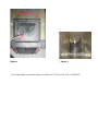
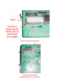
Validator Update Instructions for Rowe BC3500 $1-$20
Kit Overview
The purpose of the kit is to replace the Rowe BA50 transport and stacker with a 120 volt
Mars validator with a compact mask. The kit and these instructions pertain to a Rowe BC3500,
this is a front-loading changer with three hoppers. There are 2 variations of the kit, one will
process $1-$5 and the second $1-$20. This kit is designed for dollar bill changers that are
not used to make change for a coin. If you are accepting coins please, contact us for a coin
interface kit. This stock kit will work in changers with board numbers 65069006 and
65069050.
The kit will work with all 3 variations of the Rowe BILL CHANGER CONTROL COMPUTER
boards; 65069001, 65069006, and 65069050. The E prom in board versions 6509006 and
6509050 will be changed to 2.7.
If you are installing the kit with board number 65069001 two additional parts are needed.
This is the early style obsolete board. Please call us prior to beginning the conversion so
they can be sent to you. The parts kit includes a E prom and a transport by-pass harness.
Order part number KITCVR65069001-Eprom costing $10.00. We can be reached at Capital
Vending 800 814-7756.
The installation information is intended for experienced personnel familiar with the operation
of these components. All of the installation procedures must be reviewed and understood
prior to installing the kit. The installation instructions are based upon a dollar bill changer
that has not been modified from the original factory configuration. If the machine has been
altered in any way, restore the machine to the original factory configuration prior to
beginning the conversion. The installer must know the proper procedures to replace an E
prom.
Kit Components
The kit contains the following parts:
Module in black plastic box; labeled BC1200/1400/3500
Metal validator slide plate with slim slot
Milled mask used to replace factory mask on the validator
E prom with label BC3500 V2.7
One “low coins” screws and harness
Additional Required Items Not Included With Kit
Working Mars validator – Model AE2411/AE2451, VN2511, or AE2611
The four 11-32 hex nuts used to mount the Mars validator to the validator slide plate are
included in the Mars validator shipping box.
Dollar bills to test the validator and verify operation of the kit
Electrical tape
Tools Required
11/32”, ¼”, and 3/8” long handle nut drivers
Pliers
Small screwdriver or IC removal tool
Optional Tools Required for “low coins” screw installation
Drill
5/16” drill bit
Installation Instructions
1. Unplug the power cord from the wall and open the door of the changer.
2. Remove the BA50 bill transport by unplugging the harness at the 15-position harness
connector. A 12-inch harness will still be connected to the side of the BA50 transport.
3. Remove the bill box from the stacker assembly.
4. Remove the stacker assembly by unscrewing the two ¼” screws at the top of the
assembly. It may be necessary to hold the nuts under the assembly with a pair of
pliers. [For changers with a dual stacker remove the two ¼” screws that secure the
stacker assembly base to the bill box bracket. The bill box bracket can remain in the
changer] Disconnect the harness from the upper rear right hand side. Slide the
stacker assembly forward out of the changer. Replace the upper two screws and nuts.
The original stacker harness will not be connected to any component.
5. Set the dip switches on the 120 volt Mars validator per the label on the kit Module.
6. Unplug the 9 position harness at the Coin Acceptor Assembly.
7. Insert the 9 position harness from the new Module into the open connector. This kit is
not designed for use in a changer that accepts coins. The 9 position female connector
on the Coin Acceptor Assembly will remain open. If you need to accept coins, please
contact us for a coin interface kit.
8. Remove the three hoppers from the Coin Dispenser Assembly 6-50275-10.
9. Unbolt the Coin Dispenser Assembly by removing both 3/8” bolts.
10. Pivot the assembly forward, it does not need to be removed. [If you are having trouble
connecting the new harness you may wish to disconnect the harness from the Coin
Dispenser Assembly so it can be removed.]
11. Feed the harness with the two 3 position connectors from the Module through the barrier
wall toward the left wall of the changer. There is a large hole with an insulating ring
toward the upper rear of the wall.
12. Unplug the main power harness from the connector at the far left of the Power Control
Center Assembly (65042606).
13. Plug the 3 position male plug from the Module into the now open connector on the
Power Control Center Assembly. Plug the machine harness into the female side of the
harness.
14. Set the Coin Dispenser Assembly back into place and secure using both bolts. If the
harness was disconnected be sure to reconnect the harness.
15. Replace the 3 hoppers.
16. Remove the factory installed black plastic mask from the Mars validator, it is held in
place with 4 screws. Install the mask from the parts kit that has the upper section
removed.
17. Mount the validator onto the metal validator slide plate; the four 11-32 keps nuts are
supplied with the validator. A 12 inch factory harness may be connected to the validator
when it is removed from the box. Unplug this harness, as it is not used with the kit. If
the validator’s dip switches have not been set, set them now. The label on the Module
lists the various settings.
18. Slide the validator plate assembly down the tracks that originally secured the BA50
transport. Attach the harness from the Module with the long black connector to the
validator. Note the position of the two “keyed pins” when attaching the connector.
19. Secure the Module in a safe location. The recommended location is in the alarm canister
clips located directly behind the coin acceptor assembly.
20. Remove either of the 2 wires from the coin return switch; red or black. Wrap the
terminal in electrical tape.
21. Remove the BILL CHANGER CONTROL COMPUTER and place it on a table. The E prom
needs to be replaced.
22. Remove the cover and replace the E prom. Be sure to observe polarity. The side with
the divot is silk screened on the board as a reference. Replace the cover.
23. Reinstall the BILL CHANGER CONTROL COMPUTER and reconnect all five harnesses.
24. Plug the changer back into the wall and turn the power switch to the ON position.
25. At this point the BILL CHANGER CONTROL COMPUTER is reprogrammed.
The 2 most popularly used programs are described below. The programming for the MC
mode assumes 4 quarters will be dispensed for each dollar value inserted. If you are
dispensing dollar coins divide the number of coins to be dispensed by 4. The below
instructions can be used as a basis for substituting your own values if needed. The values
you are programming may seem odd, however the validator now controls the
denominations accepted. The MC mode is recommended if you are dispensing the same
value coin in all 3 hoppers. The operation of the MC Mode is described on page 2-11 in the
Rowe BC-3500 Bill & Coin Changer Field Service Manual and Parts Catalog; seventh edition.
It is also described on page 2-12 in the Rowe BC-1200/1400 Bill & Coin Changer Field
Service Manual and Parts Catalog; fifth edition.
MC MODE - 4 COINS PER DOLLAR VALUE
A. Slide the BILL CHANGER CONTROL COMPUTER forward so it is easy to view the blue
display and access the programming buttons.
B. Slide the mode switch upwards to the programming mode, the display will read TEMP
COUNTERS.
C. Depending upon the vintage of the BILL CHANGER CONTROL COMPUTER, the
FUNCTION button may be labeled as FUNCTION or FUNCTION-ERROR RESET. These
instructions refer to the button as FUNCTION.
D. Press the FUNCTION button, the display will read PERM COUNTERS.
E. Press the FUNCTION button, the display will read PROGRAMMING __ __ __ __. If a
security code was entered earlier enter the code now.
F. Press the FUNCTION button, the display will read MC PAYOUT. It must be set to ON.
Use either of the COUNT SWITCHES BUTTONS to set this option to ON.
G. Press the FUNCTION button, the display will read HOP VAL; the value of coins for the
left hopper will be flashing. Press the VALUE button until the display reads T1.
H. Press the HOPPER button; the display will advance to the center hopper. Press the
VALUE button until the display reads T1.
I. Press the HOPPER button; the display will advance to the right hopper. Press the
VALUE button until the display reads T1.
J. Press the FUNCTION button, the display will read ACCEPT 1; this is set to NO. The
NO and YES options are toggled using the COUNT SWITCHES.
K.
L.
M.
N.
O.
P.
Q.
R.
S.
T.
U.
Press the VALUE button, the display will read ACCEPT 2; this is set to NO.
Press the VALUE button, the display will read ACCEPT 5; this is set to YES.
Press the VALUE button, the display will read ACCEPT 10; this is set to NO.
Press the VALUE button, the display will read ACCEPT 20; this is set to NO.
Press the VALUE button, the display will read ACCEPT 25; this setting must be set to
YES.
Press the VALUE button, the display will read ACCEPT 25A; this setting is set to NO.
Press the VALUE button, the display will read ACCEPT 50; this is set to YES.
Press the FUNCTION button, the display will show 25 PAY ___ MC MC MC. Use the
COUNT SWITCH BUTTONS to set the value to 4. Use the COUNT SWITCHES to
change the value. This value determines the number of coins to be dispensed for a
$1 bill; twice the amount of coins for a $2 bill.
Press the VALUE button, the display will show 50 PAY ___ MC MC MC. Use the
COUNT SWITCHES BUTTONS to set the value to 20. Use the COUNT SWITCHES to
change the value. This value determines the number of coins to be dispensed for a
$5 bill.
At this point all of the programming changes needed for the kit have been made,
slide the function button down to the NORMAL OPERATING MODE. The display will
indicate Storing New Data.
The walking blue dash will begin scrolling.
NON MC MODE
A. Slide the BILL CHANGER CONTROL COMPUTER forward so it is easy to view the blue
display and access the programming buttons.
B. Slide the mode switch upwards to the programming mode, the display will read TEMP
COUNTERS.
C. Depending upon the vintage of the BILL CHANGER CONTROL COMPUTER, the
FUNCTION button may be labeled as FUNCTION or FUNCTION-ERROR RESET. These
instructions refer to the button as FUNCTION.
D. Press the FUNCTION button, the display will read PERM COUNTERS.
E. Press the FUNCTION button, the display will read PROGRAMMING __ __ __ __. If a
security code was entered earlier enter the code now.
F. Press the FUNCTION button, the display will read MC PAYOUT. It must be set to
OFF. Use either of the COUNT SWITCHES BUTTONS to set this option to OFF.
G. Press the FUNCTION button, the display will read HOP VAL; the value of coins for the
left hopper will be flashing. Press the VALUE button until the display reads T1.
H. Press the HOPPER button; the display will advance to the center hopper. Press the
VALUE button until the display reads T1.
I. Press the HOPPER button; the display will advance to the right hopper. Press the
VALUE button until the display reads T1.
J. Press the FUNCTION button, the display will read ACCEPT 1; this is set to NO. The
NO and YES options are toggled using the COUNT SWITCHES.
K. Press the VALUE button, the display will read ACCEPT 2; this is set to NO.
L. Press the VALUE button, the display will read ACCEPT 5; this is set to YES.
M. Press the VALUE button, the display will read ACCEPT 10; this is set to NO.
N. Press the VALUE button, the display will read ACCEPT 20; this is set to NO.
O. Press the VALUE button, the display will read ACCEPT 25; this setting must be set to
YES.
P. Press the VALUE button, the display will read ACCEPT 25A; this setting is set to NO.
Q. Press the VALUE button, the display will read ACCEPT 50; this is set to YES.
R. Press the FUNCTION button, the display will show 25 PAY ___ ___ ___. Use the
COUNT SWITCH BUTTONS to change the value for the left hopper to the amount of
coins to be dispensed when a $1 bill is inserted. Press the HOPPER button to
advance to the center hopper value. Use the COUNT SWITCHES to set the value to
the amount of coins to be dispensed when a $1 bill is inserted. Press the HOPPER
button to advance to the right hopper value. Use the COUNT SWITCHES to set the
value to the amount of coins to be dispensed when a $1 bill is inserted. This value
determines the number of coins to be dispensed for a $1 bill; twice the amount of
coins for a $2 bill.
S. Press the VALUE button, the display will show 50 PAY ___ ___ ___. This value
determines the number of coins to be dispensed for a $5 bill. Use the COUNT
SWITCHES BUTTONS to change the value for the left hopper to the amount of coins
to be dispensed when a $5 bill is inserted. Press the HOPPER button to advance to
the center hopper value. Use the COUNT SWITCHES to change set the value to the
amount of coins to be dispensed when a $5 bill is inserted. Press the HOPPER
button to advance to the right hopper value. Use the COUNT SWITCHES to change
set the value to the amount of coins to be dispensed when a $5 bill is inserted. At
this point all of the programming changes needed for the kit have been made, slide
the function button down to the NORMAL OPERATING MODE. The display will
indicate Storing New Data.
T. The walking blue dash will begin scrolling.
Insert several $1.00 bills and then $5.00 bills to confirm proper operation.
Installation Instructions for Hopper “Low Coins” Screws in Rowe
Dollar Bill Changers for Kit Modules accepting $10 and $20
These instructions apply to the final step of installing a kit Module to upgrade a Rowe
changer for the acceptance of $10 and $20.
Upon completion of the installation of the kit module, the changer should be tested. The
changer can now make change for $10 and $20 dollar bills. When a $10 bill is inserted the
amount of coins programmed for a $5 pay out is dispensed twice. When a $20 bill is
inserted the amount of coins programmed for a $5 pay out is dispensed 4 times. Be sure
the dip switches on the Mars AE2611 validator is set up to accept $10 and/or $20 bills and
test the kit.
Upon verification that the kit and changer are working properly a low coins screw is
installed. This must be installed to prevent short changing a customer. If the changer is in
an attended location and the hoppers never empty, it is not necessary to install the low
coins screw.
The screw is used to detect ground through the coins in the hopper. When coins are not
touching the screw and the metal wall of the hopper the Module will disable the validator
until more coins are inserted. The kit Module will automatically reset when additional coins
are inserted.
MC PAYOUT INFORMATION
If the changer is being used in the MC mode, a low coins screw sensor will only need to be
installed in the last hopper to be emptied; left hopper on 2 hopper models.
The parts kit consists of a single harness. If you are not using the MC Mode, the hopper
that will empty first should be monitored. The Module is capable of monitoring up to 3
hoppers. Additional harnesses are available at no charge by calling (800) 814-7756.
INSTALLATION INSTRUCTIONS
1. Turn off the changer.
2. Remove the hopper(s) from the changer and set it in a work area. If it is filled with
coins, remove the coins.
3. Drill an 11/64” hole in the black plastic area at the bottom of the hopper. The hole
should be located at the center of the hopper and 7/8” form the very bottom of the
plastic. Positioning is important so that a coin does not get wedged between the screw
and the hopper body. See Figure 1.
4. Insert the screw through the hole. Reach your hand into the hopper and align the nut.
Begin tightening the screw while holding the nut. When the nut is almost fully
tightened, slip the open spade terminal under the screw head. Finish tightening the
screw so the harness is held securely in place. The terminal should be positioned so that
it is vertical, “3:00 or 9:00”. See figures 1 and 2.
5. Once the hopper has been modified place it back in the changer.
6. Run the harnesses directly down to the bottom of the hopper and then across towards
the module. Be sure to position the harness(es) so they do not interfere with the coin
delivery or the other hoppers.
7. Disconnect one of the black wires (with pick insulators) terminals at the module. Any of
the 3 can be disconnected.
8. Connect the wire from the hoppers to the now open female connector. The wires with
the male terminals are now left open.
9. Confirm there are not any open female connectors, as this will disable the
validator.
10. Load coins into the hoppers so the screw threads are covered.
11. Turn on the changer. After a 10 second warm up period the validator will accept bills.
12. You are finished.
Installation Instructions for Hopper “Low Coins” Screws in Rowe
Dollar Bill Changers for Kit Modules accepting $10 and $20
These instructions apply to the final step of installing a kit Module to upgrade a Rowe
changer for the acceptance of $10 and $20.
Upon completion of the installation of the kit module, the changer should be tested. The
changer can now make change for $10 and $20 dollar bills. When a $10 bill is inserted the
amount of coins programmed for a $5 pay out is dispensed twice. When a $20 bill is
inserted the amount of coins programmed for a $5 pay out is dispensed 4 times. Be sure
the dip switches on the Mars AE2611 validator is set up to accept $10 and/or $20 bills and
test the kit.
Upon verification that the kit and changer are working properly a low coins screw is
installed. This must be installed to prevent short changing a customer. If the changer is in
an attended location and the hoppers never empty, it is not necessary to install the low
coins screw.
The screw is used to detect ground through the coins in the hopper. When coins are not
touching the screw and the metal wall of the hopper the Module will disable the validator
until more coins are inserted. The kit Module will automatically reset when additional coins
are inserted.
MC PAYOUT INFORMATION
If the changer is being used in the MC mode, a low coins screw sensor will only need to be
installed in the last hopper to be emptied; center hopper on 3 hopper models.
The parts kit consists of a single harness. If you are not using the MC Mode, the hopper
that will empty first should be monitored. The Module is capable of monitoring up to 3
hoppers. Additional harnesses are available at no charge by calling (800) 814-7756.
INSTALLATION INSTRUCTIONS
1. Turn off the changer.
2. Remove the hopper(s) from the changer and set it in a work area. If it is filled with
coins, remove the coins.
3. Drill an 11/64” hole in the black plastic area at the bottom of the hopper. The hole
should be located at the center of the hopper and 7/8” form the very bottom of the
plastic. Positioning is important so that a coin does not get wedged between the
screw and the hopper body. See Figure 1.
4. Insert the screw through the hole. Reach your hand into the hopper and align the
nut. Begin tightening the screw while holding the nut. When the nut is almost fully
tightened, slip the open spade terminal under the screw head. Finish tightening the
screw so the harness is held securely in place. The terminal should be positioned so
that it is vertical, “3:00 or 9:00”. See figures 1 and 2.
5. Once the hopper has been modified place it back in the changer.
6. Run the harnesses directly down to the bottom of the hopper and then across
towards the module. Be sure to position the harness(es) so they do not interfere
with the coin delivery or the other hoppers.
7. Disconnect one of the black wires (with pick insulators) terminals at the module.
Any of the 3 can be disconnected.
8. Connect the wire from the hoppers to the now open female connector. The wires
with the male terminals are now left open.
9. Confirm there are not any open female connectors, as this will disable the
validator.
10. Load coins into the hoppers so the screw threads are covered.
11. Turn on the changer. After a 10 second warm up period the validator will accept
bills.
12. Insert several $1.00, $5.00, $10, and $20 dollar bills to confirm proper operation
13. You are finished.
Figure 1
Figure 2
For technical help or questions contact us at 800 814-7756 from 9:00 AM – 4:30PM EST.