1
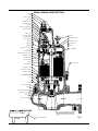
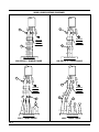
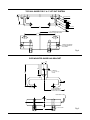
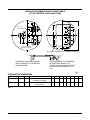
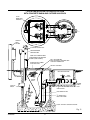
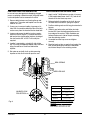
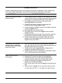
3WHV, V3WHV
Non-Clog Pumps
Installation and
Service Manual
V3WHV
3WHV
Please fill out the attached
Start-Up Report and return to
the warranty department.
23833A55
Rev 05/08
PLUG, PIPE 1
3WHV & V3WHV CROSS-SECTION
CABLE 2
CONNECTOR, CABLE 3
CAP, CORD 4
SCREW, CAP (3 REQ’D.) 5
SCREW, MACH. (3 REQ’D.) 6
LOCKWASHER 7
CONNECTOR, SCREW (3 REQ’D.) 8
PLATE, UPPER SEALING 9
9
SCREW, SPECIAL 10
GROMMET, SEALING 11
38 BOLT, EYE
PLATE, LOWER SEALING 12
39 SCREW, DRIVE (2 REQ’D.)
GASKET, TETRASEAL 13
40 PLATE, NAME (2 REQ’D.)
WIRE, RED 14
WIRE, WHITE 15
41 TAG, NAME PLATE
WIRE, BLACK 16
42 WIRE, TAG
CONNECTOR, BUTT (3 REQ’D.) 8A
43 OIL, TRANSFORMER
PLUG, PIPE 17
EMBLEM, OIL FILL 18
WASHER, FINGER SPRING (2 REQ’D.) 19
BEARING, BALL UPPER 20
TIE, CABLE (2 REQ’D.) 21
ROTOR WITH SHAFT 22
STATOR 23
44 SCREW, CAP (4 REQ’D.)
HOUSING, MOTOR 24
BEARING, BALL LWR. 25
HOUSING, SEAL & LWR BRG. 26
GASKET, TETRASEAL 27
SEAL, 11/4” SHAFT 28
(REMOVE SPRING HOLDER)
KEY 29
/
3 16
5
SEALANT 31
SCREW, CAP (4 REQ’D.) 32
GASKET 33
WASHER, RETAINING, WITH PIN 34
AIR VENT
LOCKWASHER, LOCK BRG. 35
IMPELLER 36
CASE, VOLUTE 3WHV 37
FLATTEN TWO TABS LOCATED 180º FROM WASHER
LOCKING PROJECTION. FLATTEN ONE ON EACH
SIDE OF PIN. AFTER ASSEMBLY OF HEX HEAD CAP
SCREW, BEND REMAINING TABS UP AGAINST HEX
HEAD.
37 CASE, VOLUTE V3WHV SERIES
23833A55
2
Fig. 1
3WHV & V3WHV PUMP DIMENSIONS
61/16
154 mm
61/16
154 mm
217/32
64.3 mm
125/16
313 mm
427/32
123 mm
427/32
123 mm
513/32
137 mm
513/32
137 mm
8
203.2 mm
89/16
217.5 mm
71/2” DIA.
190.5 mm
89/16
217.5 mm
227/16
570 mm
251/8
3” STD. FLANGE 638 mm
231/32
71/2” DIA.
190.5 mm
97/8
251 mm
75.4 mm
1/8
3.2 mm
31/16” DIA.
77.8 mm
211/16
68.2 mm
Fig. 2
3 23833A55
PUMP MODELS
These instructions cover the installation and service
of the 3WHV and V3WHV series of non-clog pumps
and guide rail systems for the horizontal discharge
models only. Both models are designed for handling
raw sewage and waste water. Do not use for acid
waste water. The pumps have 2-vane, non-clog
impellers. The 3WHV and V3WHV will pass 21/2” dia.
solids and has a 3” std. flange discharge. Drawing
Fig. 1 shows a cross-sectional view of the pump.
Drawing Fig. 2 shows the overall dimensions of each
pump.
For single phase the white and black leads connect
to the two-line terminals and the red connects to the
start winding terminal. The green is for ground and
must be connected to a good outside ground. See
Fig. 3.
CAUTION: Never pull pump or work on control box
until incoming power is disconnected. Never run
motor until green ground conductor is connected to
a good outside ground. Never pull on electrical cable
to lift pump.
Power cables attached to the pumps are No. 10 gauge
wire. If the control panel is not located near the pump,
consult Table 3 for permissible wire gauge to run
between the control panel and the junction box at
the wet well. Wire gauge No. 10 may be used for all
pump models located within 200 feet of the control
panel.
CAUTION: In the initial installation, before sewage
is admitted to wet well, there is no danger of entering the sump, but after sewage has been in the sump
there is danger. Sewage water gives off methane
and hydrogen sulfide gases, both of which are highly
poisonous. Never enter wet well unless cover is open
and an outside blower is used to force fresh air into
the wet well. Also, the man in the wet well must wear
a harness with rope to surface so that he can be
pulled out in case of asphyxiation. One man should
not work alone.
OIL FILLED MOTOR
The motor chamber is dielectric oil filled for good
heat transfer and lubrication of bearings. The motor
requires no other oiling or greasing. Oil level in the
motor housing should be to the bottom of the oil fill
plug with the pump in a vertical position. Do not over
fill the motor housing since some space is required
for oil expansion. See Fig. 1 for oil levels. Transformer
oil SOHIO Factopure SE40 should be used and may
be purchased from your Myers dealer.
HEAT SENSOR
All 3WHV and V3WHV single phase pump motors
contain internally wired line break overloads, while
the 3WHV and V3WHV three phase pumps do not
have heat sensors. Any motor temperature above
the sensor rating will open the overload and stop the
motor. The overload will automatically close upon
cooling.
AIR VENTING
Upon initial filling of the wet well with the water, air
may be trapped in the pump volute. To vent off this
air, a 5/32” diameter hole is located in the volute.
BE SURE THIS VENT HOLE IS CLEAN AFTER ANY
SERVICE WORK ON PUMP.
CAUTION: The single phase pumps will restart without warning as the motor cools. Therefore, never do
service work on the pump unless power supply is
disconnected.
WARNING: On three phase pumps only qualified
persons shall conduct services and installation of this
pump. The pump must be wired by a qualified electrician, using an approved starter box and switching
device.
MOTOR POWER CABLE AND CONTROL CABLE
Each power cord has 4 conductors - white, black,
red and green. For 3 phase, the red, black and white
conductors connect to the 3 line terminals and the
green is connected to a good outside ground such
as a ground rod at least 8 feet into soil. Interchanging
any two of the three power conductors will reverse a
3 phase motor.
23833A55
4
PUMP MODEL TABULATION
WINDING
RESISTANCE
Model No.
HP
RPM
PH
V
Amps
3WHV10M4-21
V3WHV10M4-21
3WHV10M4-03
V3WHV10M4-03
3WHV10M4-23
V3WHV10M4-23
3WHV10M4-43
V3WHV10M4-43
3WHV10M4-53
V3WHV10M4-53
3WHV15M4-21
V3WHV15M4-21
3WHV15M4-03
V3WHV15M4-03
3WHV15M4-23
V3WHV15M4-23
3WHV15M4-43
V3WHV15M4-43
3WHV15M4-53
V3WHV15M4-53
3WHV15M4-21
V3WHV15M4-21
3WHV15M4-03
V3WHV15M4-03
3WHV15M4-23
V3WHV15M4-23
3WHV15M4-43
V3WHV15M4-43
3WHV15M4-53
V3WHV15M4-53
3WHV15M4-43
V3WHV15M4-43
3WHV15M4-21
V3WHV15M4-21
3WHV15M4-03
V3WHV15M4-03
3WHV15M4-23
V3WHV15M4-23
3WHV15M4-43
V3WHV15M4-43
3WHV15M4-53
V3WHV15M4-53
3WHV15M4-21
V3WHV15M4-21
3WHV15M4-03
V3WHV15M4-03
3WHV15M4-23
V3WHV15M4-23
3WHV15M4-43
V3WHV15M4-43
3WHV15M4-53
V3WHV15M4-53
Locked
Rotor
Amperes
Starting
Code
Main
BL-W
Start
BL-R
W-R
1
1750
1
230
8
50
J
1.55
1.57
3.12
1
1750
3
200
5.4
36
K
2.07
2.07
2.07
1
1750
3
230
4.5
32
K
2.69
2.69
2.69
1
1750
3
460
2.3
19
M
10.75
10.75
10.75
1
1750
3
575
1.8
13
J
19.10
19.10
19.10
11/2
1750
1
230
10
50
J
1.55
1.57
3.12
11/2
1750
3
200
6.6
36
K
2.07
2.07
2.07
11/2
1750
3
230
5.5
32
K
2.69
2.69
2.69
11/2
1750
3
460
2.8
19
M
10.75
10.75
10.75
11/2
1750
3
575
2.2
13
J
19.10
19.10
19.10
2
1750
1
208
15
50
J
1.18
3.90
5.08
2
1750
3
230
12
36
J
2.43
3.40
5.83
2
1750
3
200
8.4
32
J
2.21
2.21
2.21
2
1750
3
230
7
19
J
2.05
2.05
2.05
2
1750
3
460
3.5
13
L
8.20
8.20
8.20
2
1750
3
575
2.8
13
J
15.65
15.65
15.65
3
1750
1
230
21
101
J
.83
2.38
3.21
3
1750
3
200
15
66
J
1.29
1.29
1.29
3
1750
3
230
12
58
J
1.46
1.46
1.46
3
1750
3
460
6
29
J
5.80
5.80
5.80
3
1750
3
575
5
21
H
11.15
11.15
11.15
5
1750
1
230
34
101
J
.83
2.38
3.21
5
1750
3
200
24
66
J
.74
.74
.74
5
1750
3
230
21
58
J
.89
.89
.89
5
1750
3
460
10.5
29
J
3.54
3.54
3.54
5
1750
3
575
8.4
21
H
5.69
5.69
5.69
TABLE 1
5 23833A55
ELECTRICAL COMPONENTS SINGLE PHASE ONLY
Model No.
H.P.
3WHV10M4-21
V3WHV10M4-21
1
3WHV15M4-21
V3WHV15M4-21
11/2
3WHV20M4-01
V3WHV20M4-01
2
3WHV20M4-21
V3WHV20M4-21
2
3WHV30M4-21
V3WHV30M4-21
3&5
Start Cap. No.
Run Cap. No.
Start Relay, No.
12141A007
110 VAC
1020-1224 MFD
12141A007
110 VAC
1020-1224 MFD
12141A012
220 VAC
574-688 MFD
12141A006
220 VAC
270-324 MFD
12141A008
220 VAC
430-516 MFD
12749A004
370 Volt
15 MFDS
23749A004
370 Volt
15 MFDS
23186A000
410 Volt
25 MFDS
19076A000
361-430 Volt
25 MFDS
23839A000
370 Volt
30 MFDS
21990A003 (40 Amp)
PU, FL 150-160 DO, VL 40
21990A003 (40 Amp)
PU, FL 150-160 DO, VL 40
21990A010 (16.7 Amp)
PU, FL 250-270 DO, VL 110
21990A002 (33 Amp)
PU, FL 300-320 DO, VL 100
21990A004 (43 Amp)
PU, FL 290-310 DO, VL 95
TABLE 2
CABLE SIZE REQUIRED DEPENDING ON MOTOR HORSEPOWER,
VOLTAGE, AND DISTANCE OF CONTROL PANEL FROM PUMP
MAX. OFFSET DISTANCE (FEET) PER WIRE GA.
Motor
Horsepower
Phase
Voltage
14 A.W.G.
12 A.W.G. 10 A.W.G.
8 A.W.G.
6 A.W.G.
1
1
230
292
465
740
1175
1870
11/2
1
230
124
385
615
980
1560
2
1
208
140
225
355
565
900
2
1
230
205
330
520
830
1320
3
1
230
153
245
385
615
980
5
1
230
92
145
230
370
590
1
3
200
315
500
790
1260
2000
1
3
230
430
685
1090
1730
2750
1
3
460
1720
2740
4360
1
3
575
2690
4280
1
1 /2
3
200
260
410
655
1040
1655
11/2
3
230
345
545
870
1380
2195
11/2
3
460
1375
2185
3475
11/2
3
575
2160
3435
2
3
200
200
315
500
800
1275
2
3
230
260
420
665
1055
1680
2
3
460
1050
1670
2660
2
3
575
1635
2600
3
3
200
150
240
280
605
960
3
3
230
205
330
520
830
1320
3
3
460
825
1310
2085
3315
3
3
575
1285
2050
3260
5
3
200
110
170
270
430
690
5
3
230
150
235
375
600
950
5
3
460
595
947
1505
2395
3805
5
3
575
930
1480
2355
3740
TABLE 3
23833A55
6
BLACK
RED
RED
8A8A
T3
T1
T1 T2
T2
T3
T3
T1
T1
T2
T2
T3
BLACK
RED
RED
BLUE
BLUE
BLACK
BLACK
RED
RED
BLUE
BLUE
BLACK
8A
8A
GROUND
GROUND
GROUNDGROUND
SCREW
SCREW
SCREW SCREW
GROMMET
GROMMET
GROMMET
GROMMET
BLACK
RED
RED
GROUND
GROUND
GROUNDGROUND
SCREW
SCREW
SCREW SCREW
GROMMET
GROMMET
GROMMET
GROMMET
8A8A
8 8
8
N
GREE
N
E
E
R
G
8
WHT.
WHT.
BLACK
BLACK
RED
RED
WHT.
WHT.
BLACK
8A
8A
WH
WHB T.
TL. K.
BLK.
RED
RED
WH
ETN.
E
BW
GR
LKH.T.
N
E
E
GR BLK
RED .
RED
8 8
8
WHT.
WHT.
BLACK
BLACK
RED
RED
WHT.
WHT.
BLACK
8
N
GREE
N
E
E
R
G
WH
WHB T.
TL. K.
BLK.
RED
RED
WH
ETN.
E
BW
GR
LKH.T.
N
E
GRE BLK
RED .
RED
3WHV & V3WHV WIRING DIAGRAMS
MOTOR STATOR
MOTOR
STATOR
MOTOR STATOR
MOTOR
STATOR
MOTOR STATOR
MOTOR
STATOR
MOTOR STATOR
MOTOR
STATOR
8 8
8
MOTOR STATOR
MOTOR
STATOR
MOTOR STATOR
MOTOR
STATOR
Fig. 3
230 V - THREE PHASE
230
- THREE
PHASE
230 V - THREE
PHASE
230
V -V THREE
PHASE
T4
T4
T9
T9
8 8
T3
T3
T1
T1
T2 T6
T6
T2
T3
T3
T8
T8
T6
T6
T4
T4
T8
T8
T2
8
T2
T1
T1
8
T7
T7
8A8A
8B8B
T3T1
T1T3
T2
8A
8A
T6
T2 T6
T5
T2
T5
T1 T4
T4
T1 T6
T6
T5
T5
T4
T4
T8
T7
T7
T9
T9
T8
T8
T7
T7
T2
T3
T3
T9
T9
T8
8B
8B
GROUND
GROUND
GROUNDGROUND
SCREW
SCREW
SCREW SCREW
GROMMET
GROMMET
GROMMET
GROMMET
WH
WH ITE.
ITLE
B
A
BL . CK
ARCE
D
RE K
WH D
W ITE
BLHITE.
AC .
RBELACK
D
RE K
D
BLACK
RED
RED
WHT.
WHT.
BLACK
BLACK
RED
RED
WHT.
WHT.
BLACK
GROUND
GROUND
GROUNDGROUND
SCREW
SCREW
SCREW SCREW
GROMMET
GROMMET
GROMMET
GROMMET
N
GREE
N
E
E
GR
8
T5
T5
T9
T9T7
T7
T5
T5
8 8
8
WH
WH T.
B.LK.
T
BLRED
K.
RED
WH
WEHTE.N
B
GR
LKT..
EN
GRERED
BLK.
RED
8
N
GREE
N
E
E
GR
WH
WHB T.
TL. K.
BLK.
RED
RED
WH
EHTN.
E
BW
GR
L
K
N
.T.
GREEBLK
RED .
RED
200 OR 575 V - THREE PHASE
208 OR 230 V - SINGLE PHASE
200
575
- THREE
PHASE
208
230
-PHASE
SINGLE
PHASE 200 OR 200
575
V OR
- THREE
PHASE
OR
575
V -V THREE
PHASE
208 OR 208
230
V OR
- SINGLE
OR
230
V -V SINGLE
PHASE
MOTOR STATOR
MOTOR
STATOR
MOTOR STATOR
MOTOR
STATOR
460 V - THREE PHASE
460
- THREE
PHASE
460 V - THREE
PHASE
460
V -V THREE
PHASE
7 23833A55
INSTALLING RAIL SYSTEM PARTS
(Horizontal Models Only)
MOUNTING COVER, DISCHARGE BASE & RAILS
1. Set concrete cover with hatch opening in position.
If base cover is to be steel or aluminum, secure
the cover to basin walls with expansion bolts.
ATTACHING MOUNTING PLATE TO PUMP
1.
With the gasket between the mounting plate and
pump discharge, attach the mounting plate with
the bolts supplied. See Fig. 6. The mounting plate should be turned so that two pins are horizontal and one pine vertical pointing up.
2.
Bolt rail guide plates, Fig. 4 to frame. Stainless
steel bolts are screwed through frame angles when
shipped and nuts are provided to hold the plate. Brackets have vertical slots so that they can be adjusted for final fit on rails. The plate has slots so
the two plates in a duplex system can be adjusted to obtain 16” center-to-center distance between pumps.
3.
Lower the base or base/elbow assembly into the basin. IMPORTANT - Concrete bottom must be level and smooth for mounting discharge base. See Fig. 6.
3.
Check pump rotation is 3 phase. Connect power cords to motor control panel and lay pump on its
side so that impeller can be seen. Turn all switches to off position.
4.
Approximately position the base such that the pipe rail locating pins protruding from the top of
the base are directly below the rail guides attached at the top of the basin; these rail guides should be
positioned about mid-way in the vertical adjustment slots. Cut the pipe guide rails to length and install between the rail guides at the top of the basin and
the pins on the base. Guide rails are ¾” Schedule 40, galvanized or stainless steel pipe.
4.
Close main circuit breaker, then jog manual switch to ON then OFF. Note rotation direction of impeller
Impeller must turn counterclockwise as looking
into the impeller’s inlet. If rotation is wrong,
interchange any two line leads to the motor. BE SURE MAIN BREAKER IS OFF WHEN THIS CHANGE IS MADE. MARK WIRES SO THEY CAN BE REPLACED IN SAME ORDER.
5.
Using a bubble level held against the rails, move
the base until both rails are vertical. Now mark
the position of the base, hold down bolts through
the holes in the base.
5.
Mount the guide plate on the vertical pin of the
mounting plate. Position the guide openings
parallel with the face of the mounting plate. Snug
the two set screws but do not over tighten at this
time.
6.
Remove the guide rails and move the base aside
to allow drilling of the concrete for 5/8” expansion
bolts 2 ½” long. Then move the base over the bolt
holes and re-install the guide rails. Recheck rails
with bubble level and install the bolts.
7.
Install discharge pipe as required by the particular
job specifications. If one size larger discharge pipe is required, a reducing elbow may be attached to the base.
6.
Slowly lower the pump down the guide rails to
the base. Inspect the mating of the mounting
plate face to the base face, they should be flat against one another. If necessary, loosen the two set screws of the guide plate and rotate the guide plate until an equal amount of clearance exists between the guide plate and the guide rails.
Retighten the set screws. If no adjustment was
necessary, check that the set screws are tight.
8.
If the top rail guide plate can not be attached to
the hatch cover frame, a special rail bracket (Fig.
5) can be furnished for mounting directly to a pipe
cemented in the basin wall. This bracket is set and
aligned with discharge base the same as described
for the rail guide plate attached to the frame.
23833A55
LOWERING PUMP TO DISCHARGE BASE
1. Attach lifting chains to eye bolts on top of the pump with the clevis furnished.
2. A hook is located on the top guide rail bracket to hold the upper end of the chain when not in use.
7. The pumps are now properly positioned for operation.
8
TOP RAIL GUIDE FOR 3” & 4” LIFT-OUT SYSTEM
3/8
1
PLATE MOUNTING
2
WASHER
4 REQ’D
15/32 x 1 x 1/16
3
3
4
7
4
5
SC REW CAP
4 REQ’D
7/16 -14 x 1
SUPPORT
2 REQ’D
HOOK FOR LIFT CHAIN
NUT
5/16 - 18
16” TO CENTERLINE OF SECOND GUIDE
PLATE IN DUPLEX PUMP SYSTEM
111/2
HOLES IN SUPPORT ARE
SLOTTED FOR VERTICAL
ADJUSTMENT
3/4 SCH. 40 PIPE
Fig. 4
PIPE MOUNTED GUIDE RAIL BRACKET
115/16
DIA.
35/8
SCREW, SET
7/16 - 14 UNC x 5/8
2 REQ’D
75/8
16” TO CENTERLINE OF
SECOND BRACKET IN
DUPLEX PUMP SYSTEM
HOOK FOR LIFT CHAIN
7
3/4 SCH. 40 PIPE
9 Fig. 5
23833A55
TYPICAL INSTALLATION
19
103/16
COVER FRAME
RAIL GUIDE SUPPORT PLATE BOLTS
TO HATCH COVER FRAME
CHAINS AND CLEVIS
NOT SHOWN
GUIDE RAILS (BY OTHERS)
DISCHARGE PIPE
(BY OTHERS)
PLATE, GUIDE
PINS
POST
GASKET
GASKET
SCREW CAP
8 REQ’D FOR 3”
PLATE
MOUNTING
23833A55
BASE
10
61/2”
BOTTOM OF BASIN MUST
HAVE SMOOTH LEVEL
TROWLED SURFACE
Fig. 6
INSTALLATION DIMENSIONS FOR 3WHV PUMPS
LIFT-OUT SYSTEM, HATCH AND COVER
B
USE 3/4 x 21/2
EXPANSION BOLTS
2
H
31/2
51/4
7
111/2 7
E
A
A
4
B
C
A
A
C
G
111/2 7
53/4
B
SIMPLEX & DUPLEX
BASE & DISCHARGE
F
D
5/8 x 1 (6) SLOTS USE 1/2 x 21/2 EXPANSION BOLTS
HATCH ASSEMBLY TO BE CEMENTED
IN PLACE WHEN BASIN TOP IS
POURED. ANCHORS AND PLATE MTG.
BOLT HEADS ARE CEMENTED INTO
TOP.
SURFACE BELOW FRAME MUST BE
SMOOTH AND NOT PROTRUDE INTO
FRAME OPENING.
Fig. 7
INSTALLATION DIMENSIONS
Pump
3WHV Simplex
Disch. Basin
3”
48”
3WHV Duplex
3”
60”
Cover/Hatch
A
B
HCD-48WHV, HCR-48HWV,
HA-48WHV, HS-48WHV
0
57/8
C
D
HCD-60, HCR-60
HA-60, HS-60
11
115/8 65/16 32
65/16 23
E
F
G
361/2 91/4 181/4
46
15
23
H
54
66
TABLE 4
11 23833A55
TYPICAL INSTALLATION FOR DUPLEX SYSTEM
WITH CONCRETE BASIN AND OUTSIDE VALVE BOX
FLCW
MOUNTING
BRACKET
SERVICE
POLE
OPTION
FLASHING ALARM LIGHT
WEATHERPROOF
CONTROL BOX
CORD SEAL CONNECTIONS
FOR POWER AND CONTROL
CORDS (NOT SHOWN)
HINGED ACCESS DOOR
ALUM. OR STEEL
OPT. JUNCTION BOX
MUST BE USED IF CONTROL BOX
IS OFFSET FROM BASIN
TOP RAIL SUPPORT
OUTSIDE VALVE BOX
GATE
VALVE
LIFTING
CHAIN
BELOW
FROST
LINE
INLET AS
REQ’D
CHECK VALVE
DISCHARGE PIPING
3/4”
GUIDE RAILS –
MUST BE PLUMB
DISCH. AND RAIL SUPPORT CASTING
Fig. 11
23833A55
12
ELECTRICAL CONTROLS
(All Models)
FLOAT SWITCH INSTALLATION
1. Level Controls are held by support bracket and cords are adjusted for proper depth.
a.Lower Turn-Off Control should be set so that
pump stops when water level is about at the top
of the volute.
b.First Turn-On Control is set to start pup when
level is at height specified above pump.
c.Second Turn-On Control of a duplex pump
system is set at height specified above first turn
on control.
d.Alarm Control is set about 6” to 12” above the
highest Turn-On Control.
e.No Control should be set above basin inlet invert.
MAKING ELECTRICAL CONNECTIONS
1.
2.
If control panel is mounted directly on basin top,
the power and control wires are taken directly to
control box and are sealed in the cord plate with
cord grip connectors.
If panel is installed remote from basin, the cords
can be taken through a conduit to control panel,
or junction box can be used in the basin to make connections. The Myers junction box has a built-in
sealing connector to seal the outgoing wires. If
other than Myers junction box is used, a separate
sealing connector must be used where wires
leaves the basin. See Wiring Diagram Fig. 3.
CAUTION: If cords are taken directly through a
conduit to control box, a seal fitting must be used
at inlet of conduit to prevent gas vapors from
getting to control box. This type of installation is
generally not recommended because the sealing
cement must be broken to remove a cord.
MOTOR ELECTRICAL CONNECTIONS
Single phase motors are for 230 volts only. A special
control panel with start and run capacitors and start
relay are required for these pumps.
These control panels must be obtained from F.E. Myers
or must be approved by Myers or warranty on motor
is void. Also, warranty is void if the heat sensor and
seal fixture wires are not connected properly to control
box terminal strip.
CAUTION: Pump motor is not to be taken apart in
the field. Motors under warranty must be serviced by
Myers authorized repair station or be sent to factory.
13
23833A55
IN SUMP CONNECTION BOX, SIMPLEX SYSTEM, FLCW 3 BALL CONTROL
FLCW
HIGH LEVEL
START SWITCH
16-2
PUMP
CONTROL CORD
FLCW
ALARM CORD
16-2
PUMP
POWER CORD
FLCW
LOW LEVEL
CUT-OFF SWITCH
16-2
10-4 O
16-4
16-2
16-2
16-2
SEALING COMPOUND
DO NOT SEAL UNTIL
UNIT HAS BEEN RUN
* POWER LINES MUST BE SIZED
DEPENDING ON PUMP SIZE AND
VOLTAGE AND DISTANCE FROM
WET WELL.
SEE TABLE 2
CAN BE INDIVIDUAL WIRES
INSTEAD OF CORD AS SHOWN
Fig. 9
23833A55
14
IN SUMP CONNECTION BOX, DUPLEX SYSTEM, FLCW 4 BALL CONTROL
PUMP #1
POWER CORD
PUMP #2
POWER CORD
PUMP #2
CONTROL CORD
BL
RE ACK
D
W
H
IT
E
EN
GRE
WHIT
E
N
GR
BL
AC
K
K
AC HITE
BL
W
K
AC
BL
K
BLAC
E
IT
H
W
FLCW
ALARM CORD
16-2 (OPTIONAL)
ALARM CORD
PUMP #2 CONTROL CORD
SECONDARY PUMP ON SWITCH
PUMP OFF SWITCH
PUMP #2 POWER CORD
K
AC
BL
E
IT
H
W
PRIMARY PUMP ON SWITCH
PUMP #1 CONTROL CORD
K
AC
BL
WH
ITE
PUMP #1 POWER CORD
WHIT
E
FLCW
PUMP OFF SWITCH
16-2
CK
BLA
GR
EE
N
RE
D
EE
R
E EN
G
WH
ITE
FLCW
SECONDARY
PUMP ON SWITCH
16-2
WHIT
E
GR
EE
N
BL
AC
K
RED
WHITE
BLAC
K
K
G
R
E
WHIT
D
RE
ITE
WH
EN
RE
G
K
AC
BL
ITE
WH
D
RE
K
AC
BL
EEN
C
BLA
RED
BLACK
E
IT
H
W
K
AC
BL
FLCW
PRIMARY
PUMP ON SWITCH
16-2
BLA
CK
RE
D
N
EE
R
G
W
HIT
E
WHITE
R
ED
PUMP #1
CONTROL CORD
SEALING COMPOUND
DO NOT SEAL UNTIL
UNIT HAS BEEN RUN
BLACK
BLACK
16-2
BLACK
-4
16
WHITE
16-4
10-4 0
2
16-
WHITE
16-2
16-2
10-4 0
WHITE
BLACK
WHITE
WHITE
WHITE
BLACK
BLACK
RED
RED
RED
RED
WHITE
CAN BE INDIVIDUAL WIRES
INSTEAD OF CORD AS SHOWN
WHITE
BLACK
GREEN
GREEN
GREEN
GREEN
BLACK
* POWER LINES MUST BE SIZED
DEPENDING ON PUMP SIZE AND
VOLTAGE AND DISTANCE FROM
WET WELL. SEE TABLE 2.
15
Fig. 10
23833A55
REPLACING IMPELLER AND PUMP CASE
REMOVING PUMP CASE AND IMPELLER
In case of wear, damage due to dropping, plugged
pump, or replacing a defective motor, the pump volute
case and impeller can be removed in the field.
1. Apply Loctite™ #680 before assembly, in keyway,
in the impeller bore (lower shaft O.D.), and on the
threads of the hex head cap screw.
1. Remove bolts between seal housing flange and
volute case. The motor and impeller can now be
lifted off as a unit.
2. Before placing the impeller on the shaft, be sure
the mechanical seal and its spring are in place.
3. Position retaining washer with long pin extension in
keyway.
2. If necessary to remove impeller, lay pump on its
side. With a screwdriver bend the tabs of the lock
washer away from the heard of the hex head bolt.
3.
Loosen and remove the bolt by turning counterclockwise. Since Loctite™ is used to secure the
bolt and on the shaft/impeller interface, heating of
the shaft end to 450° to 500°F will usually be
required.
4.
Impeller is mounted by a straight fit with driving
key. Pry evenly on opposite impeller sides with two
large screwdrivers or small bars behind the
impeller.
4.
Obtain a new lockwasher and flatten two tabs
located 180° from the locking projection on the
inner edge of the washer. There should be one
flattened tab on each side of the pin extending
from the retaining washer.
5. Assemble hex head cap screw and tighten
securely.
6. Bend lockwasher tabs up against hex head of the
bolt, do not bend up the two tabs flattened on
each side of the pin in the retaining washer.
5. Set motor on end with shaft up after removing
impeller so that oil will not drain past the seal.
SEAL SPRING
IMPELLER HUB
1
2
3
4
WASHER LOCK
PROJECTION
3WHV & V3WHV
(1) KEY
(1) RETAINING
WASHER W/PIN
23609A001
(13/32 x 11/4 O.D. x 1/4 THK.)
(1) LOCKWASHER
BEARING
08001A007
(W-01)
(1) CAP SCREW
HEX HEAD
Fig. 8
23833A55
05818A074
(1/4 x 1/4 x 11/16)
19101A017
(3/8 -16 x 11/4 LG.)
FLATTEN TWO TABS LOCATED 180º FROM WASHER
LOCKING PROJECTION (FLATTEN ONE ON EACH
SIDE OF PIN).
AFTER ASSEMBLY OF HEX HEAD CAP SCREW.
BEND REMAINING TABS AGAINST HEX HEAD.
16
TROUBLE CHECK LIST
Troubles listed generally pertain to the pump and auxiliary components. Other troubles can
occur from a faulty control box, these will be listed with the control box instructions.
CONDITION
PROBABLE CAUSE
Pump runs but does not pump
liquid from basin.
1.
2.
3.
4.
5.
6.
7.
8.
Pump impeller may be air locked, this occasionally occurs on a new installation. Start and stop pump several times to purge
air. Be sure air vent hold in volute case is clean. See Fig. 1.
Run additional water into basin so that pump will be
submerged deeper to clear water.
If pump is three phase, rotation may be wrong. See
instructions for checking proper rotation.
If pump has been installed for some time and does not pump,
it may be clogged at inlet.
Discharge gate valve may be closed.
Discharge check valve may be clogged or have a broken
clapper or spring.
Discharge head may be too high. Check elevation. Maximum
pump head at zero flow is shown on pump curve sheet.
If above checks do not locate trouble, motor rotor may be
loose on shaft which allows motor to run but will not turn
impeller or only at low RPM.
Overload trips at control box
and alarm buzzer or flashing
red light comes on due to high
water level in basin.
1.
2.
3.
Push in on red reset button to reset overload. If overload
trips again after short run, pump has some damage and must
be removed from basin for checking.
Trouble may be from clogged impeller causing motor to
overload or could be from failed motor.
Trouble may be from faulty component in control box. Always check control box before removing pump.
Yellow run light stays on
continuously.
1.
2.
3.
4.
5.
Indicates H-O-A switch may be in the hand position.
Level control switch may have failed causing pump to
continue to operate when water is below lower control.
Impeller may be partially clogged, causing pump to
operate at much reduced capacity.
Gate valve or check valve may be clogged causing low pump
flow.
Pump may be air logged. Lift arm on check valve to vent off air. Also, check that the 5/32” vent hole in the volute is open.
17
23833A55
TROUBLE CHECK LIST (Cont’d)
CONDITION
Circuit breaker trips
PROBABLE CAUSE
1. Reset breaker by pushing clear down on handle then back
to on position. If breaker trips again in a few seconds it
indicates excessive load which is probably caused by a short
in the motor or control box. Check out instructions given with
control box before pulling pump.
2. If this condition happens after an electrical storm, motor or
control box may be damaged by lightning.
3. Resistance reading of the motor with lead wires disconnected
from the control box can determine if trouble is in motor or
control box.
Pump is noisy and pump rate
is low
1.
2.
3.
Impeller may be partially clogged with some foreign objects
causing noise and overload on the motor.
Impeller may be rubbing on wear ring due to bent shaft or
misalignment.
Pump may be operating too close to shut-off. Check head.
Grease and solids have
accumulated around pump
and will not pump out
of basin.
1.
2.
3.
Lower weight of level switch may be set too high.
Run pump on manual operation for several minutes with small
amount of water running into basin to clean out solids and
grease. This allows pump to break suction and surge, breaking
up the solids. If level switch is set properly, this condition
generally will not occur.
Trash and grease may have accumulated around floats
causing pump to operate erratically.
23833A55
18
STANDARD LIMITED WARRANTY
Myers warrants its products against defects in material and workmanship for a period of 12 months from the date
of shipment from Myers or 18 months from the manufacturing date, whichever occurs first - provided that such
products are used in compliance with the requirements of the Myers catalog and technical manuals for use in
pumping raw sewage, municipal wastewater or similar, abrasive free non-corrosive liquids.
During the warranty period and subject to the conditions set forth, Myers, at its discretion, will repair or replace to
the original user, the parts which prove defective in materials and workmanship. Myers reserves the right to change
or improve its products or any portions thereof without being obligated to provide such a change or improvement
for prior sold and/or shipped units.
Start-up reports and electrical schematics may be required to support warranty claims. Warranty is effective only if
Myers authorized control panels are used. All seal fail and heat sensing devices must be hooked up, functional and
monitored or this warranty will be void. Myers will only cover the lower seal and labor thereof for all dual seal pumps.
Under no circumstance will Myers be responsible for the cost of field labor, travel expenses, rented equipment,
removal/reinstallation costs or freight expenses to and from the factory or an authorized Myers service facility.
This limited warranty will not apply: (a) to defects or malfunctions resulting from failure to properly install, operate or
maintain the unit in accordance with the printed instructions provided; (b) to failures resulting from abuse, accident
or negligence; (c) to normal maintenance services and parts used in connection with such service; (d) to units which
are not installed in accordance with applicable local codes, ordinances and good trade practices; (e) if the unit is
moved from its original installation location; (f) if unit is used for purposes other than for what it is designed and
manufactured; (g) to any unit which has been repaired or altered by anyone other than Myers or an authorized
Myers service provider; (h) to any unit which has been repaired using non factory specified/OEM parts.
Warranty Exclusions: MYERS MAKES NO EXPRESS OR IMPLIED WARRANTIES WHICH EXTEND BEYOND
THE DESCRIPTION ON THE FACE HEREOF. MYERS SPECIFICALLY DISCLAIMS THE IMPLIED WARRANTIES
OF MERCHANTABILITY AND FITNESS FOR ANY PARTICULAR PURPOSE.
Liability Limitation: IN NO EVENT SHALL MYERS BE LIABLE OR RESPONSIBLE FOR CONSEQUENTIAL,
INCIDENTAL OR SPECIAL DAMAGES RESULTING FROM OR RELATED IN ANY MANNER TO ANY MYERS
PRODUCT OR PARTS THEREOF. PERSONAL INJURY AND/OR PROPERTY DAMAGE MAY RESULT FROM
IMPROPER INSTALLATION. MYERS DISCLAIMS ALL LIABILITY, INCLUDING LIABILITY UNDER THIS
WARRANTY, FOR IMPROPER INSTALLATION. MYERS RECOMMENDS INSTALLATION BY PROFESSIONALS.
Some states do not permit some or all of the above warranty limitations or the exclusion or limitation of incidental
or consequential damages and therefore such limitations may not apply to you. No warranties or representations at
any time made by any representatives of Myers shall vary or expand the provision hereof.
1101 Myers Parkway
Ashland, Ohio 44805-1969
419-289-1144
www.femyers.com
Warranty Rev 02/09
START-UP REPORT
1. SYSTEM INFORMATION
Size of Wet Well:_______________________________________Manufacturer: _____________________________
Discharge from Bottom of Basin: ________________________Discharge Location:________________________
Inlet from Bottom of Basin: _____________________________Inlet Location: _____________________________
Type of Check Valves: __________________________________Type of Piping: ____________________________
Does System Have Suction Gauges? ❑ Yes ❑ No
Suction Pressure Reading: __________________
Does System Have Discharge Gauges? ❑ Yes ❑ No
Discharge Pressure Reading:________________
Liquid Being Pumped:_______________________Temperature (F°): __________ Pct. of Solid (%):___________
Is a Sketch or Photograph of System Available? ❑ Yes ❑ No If So, Please Attach.
Any Additional Comments on System:______________________________________________________________
_______________________________________________________________________________________________
2. ELECTRICAL INFORMATION
Control Panel Part Number: _____________________________Panel Rated Amps: ________________________
Manufacturer: _________________________________________Voltage: _______________ Phase: ____________
Heater Size:___________________________________________Location of Panel to Wet Well: _______________
Incoming Line Voltage: _________________________________Actual? ___________________________________
Voltage to Pumps: _____________________________________Actual? ___________________________________
Type of Junction Box: __________________________________Manufacturer of Junction Box: ______________
Are Floats Installed in Wet Well? ❑ Yes ❑ No
Are Floats Set to Engineer’s Specs? ❑ Yes ❑ No
Are Floats Wired for Proper Sequencing? ❑ Yes ❑ No
Are Heat Sensors Hooked Up? ❑ Yes ❑ No
Is the Seal Leak Detection Hooked Up? ❑ Yes ❑ No
Any Additional Comments on Electrical: ____________________________________________________________
_______________________________________________________________________________________________
3. PUMP INFORMATION
Type of Pump:_________________________________________Serial Number of Pump: ____________________
Voltage of Pump: ________________ Phase: _______________RPM: _________________ Amps: ____________
Impeller Size:____________________ C.O.S. TDH: __________GPM: _________________
Voltage Supplied from Panel:____________________________Actual? ___________________________________
Actual Amperage (All Phases): Phase 1 Amps: ________ Phase 2 Amps: ________ Phase 3 Amps: ________
Define the Rotation of the Pump: ❑ Clockwise ❑ Counterclockwise
Method Used to Check Rotation: ❑ Viewed from the Top ❑ Viewed from the Bottom
Any Additional Comments on Pumps: ______________________________________________________________
_______________________________________________________________________________________________
4. ACKNOWLEDGE
Acknowledge that all information is accurate and proper procedures have been followed.
Customer: ___________________________________________________________________ Date: _____________
Start-up Technician:___________________________________________________________ Date: _____________
Send to Warranty Manager, 1101 Myers Parkway, Ashland, OH 44805
or Fax to 419-207-3344
or email to [email protected]
or submit online at http://forms.pentairliterature.com/startupform/startupform.asp?type=m
cut along dotted line
Distributor:__________________________________________________ Order No.: _________________________
Installing Contractor: _________________________________________ Phone: ____________________________
Sales Contact: ______________________________________________ Phone: ____________________________
Customer: ______________________________________________________________________________________
Location: _______________________________________________________________________________________