1
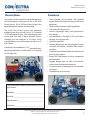
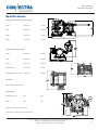
414SC Butt Fusion System
Operator’s Manual
Toll Free: (800) 654-3872 Fax: (800) 733-5993 Website: www.connectrafusion.com
Address: 39605 Independence, Shawnee, OK, 74801 USA
© Georg Fischer Central Plastics, LLC – Revised 4/2011
Operator’s Manual
414SC Butt Fusion System
Table of Contents
Description ......................................................................3
Features ..............................................................................3
Facing the Pipe ..................................................11
Pipe/Fitting Alignment ...................................11
Specifications .................................................................4
Fusing the Pipe ..................................................12
Equipment Information ..........................................5
Removing Pipe ...................................................13
Controls ..................................................................5
In the Ditch Pipe Fusion ..................................14
Power Unit Controls ............................................5
Mitered Fusions .................................................14
Clamp Liners .........................................................5
Maintenance ................................................................14
Separation from the Cart ..................................6
Guide Rods and Clamps ..................................14
Safety Precautions ......................................................6
Hydraulic System ..............................................14
Warnings & Cautions ..........................................6
Facer Assembly ..................................................15
Machine Operation Safety ...............................7
Heater Assembly ...............................................15
Operating Procedures ..............................................8
Power Unit Engine ............................................15
Preparation ............................................................8
Replacement/Acc. Parts List ...............................17
Load Pipe or Fittings ...........................................9
Fusion Pressure Charts ..........................................18
Setting Fusion Pressure .....................................9
Statement of Warranty ....................................20
Setting Heating Pressure ................................10
Notes ......................................................................21
Setting Facing Pressure ..................................10
Establish Drag ....................................................10
Toll Free: (800) 654-3872 Fax: (800) 733-5993 Website: www.connectrafusion.com
Address: 39605 Independence, Shawnee, OK, 74801 USA
© Georg Fischer Central Plastics, LLC – Revised 4/2011
2
Operator’s Manual
414SC Butt Fusion System
Features
Description
The purpose of this manual is to provide operating
and maintenance instructions for the 414SC Butt
Fusion System. The 414SC Butt Fusion System fuses
polyethylene pipe quickly and accurately.
The 414SC Butt Fusion System uses centerline
applied fusion force to butt fuse 4” IPS through
14” IPS polyethylene pipe. The machine also fuses
metric pipe sizes from 110mm through 355mm.
Clamping jaws are sized for 14” IPS pipe. Easily
insertable liners are used for pipe sizes down to 4”
and 110mm.
Clamp liners are available for 11.25° mitered fusions,
permitting fabrication of a 90° elbow in 4” through
10” IPS pipe sizes.
* Fully powered, self contained 13HP gasoline
engine drives the hydraulic pump and electric
generator.
* Three and four clamp in-ditch capabilities.
* One heater for all pipe sizes.
* Narrow, lightweight facer with quick-disconnect design.
* Accommodates 4” through 14” IPS and 110mm
through 355mm pipe sizes.
* Hydraulic pipe lifter.
* Modular design cart with locking wheel comes
standard and delivers excellent field maneuverability.
* Protected, consolidated hydraulic controls with
pressure adjustments.
* Ported for DataConnect or other competitive
data recorders.
* Rugged design with no “bells and whistles”
means fewer maintenance expenses.
* A superior piece of equipment at an extraordinary price.
* Limited three-year warranty.
Copy information listed on your Warranty Card for
your records:
Model No. _________________________________
Serial No. _________________________________
Date Received _____________________________
Distributor _________________________________
Toll Free: (800) 654-3872 Fax: (800) 733-5993 Website: www.connectrafusion.com
Address: 39605 Independence, Shawnee, OK, 74801 USA
© Georg Fischer Central Plastics, LLC – Revised 4/2011
3
Operator’s Manual
414SC Butt Fusion System
Specifications
Carriage Unit Dimensions (three clamp)
Length
33.75 inches
857 mm
Width
42.79 inches
1,087 mm
Height
25.31 inches
643 mm
Weight
404 pounds
183.3 kg
Carriage Mounted on Frame
Length
77.72 inches
1,974 mm
Width
57.94 inches
1,472 mm
Height
46.82 inches
1,189 mm
5.97 inches
152 mm
1,332 pounds
604.2 kg
Ground Clearance Total Weight (all components)
Capacities
Model 414SC - 4” IPS thru 14” IPS*
Electrical data
240 VAC Single Phase
Watts
Amps
Heater
2,500
10.4
* With the use of optional reducing liners.
Specifications are subject to change without notice.
Toll Free: (800) 654-3872 Fax: (800) 733-5993 Website: www.connectrafusion.com
Address: 39605 Independence, Shawnee, OK, 74801 USA
© Georg Fischer Central Plastics, LLC – Revised 4/2011
4
Operator’s Manual
414SC Butt Fusion System
Equipment Information
Controls
The numbering below corresponds to the numbering as shown on the hydraulic manifold.
7. Facer Motor Control: This lever is used to operate the facer
8. Directional Control Lever: Used to move the
moveable carriage. Movement to the left brings
the stationary and moveable clamps together.
Movement to the right separates the clamps.
9. Carriage Pressure Gauge: Indicates pressure in
the function selected by the Function Selector
Switch (3).
10.System Pressure Gauge: This gauge indicates
system operating pressure.
1. Operating Knob: Turned to the “set drag” position when determining pressure required
to overcome pipe drag. Returned to “operate” when ready to begin fusion operations.
2. Drag Control Knob: With Operate Knob
(1) turned to “set drag”, this knob is turned
clockwise to compensate for drag caused by
weight of pipe or other operating conditions.
3. Function Selector Switch: Used to select the
functions of facing, heating and fusion for the
purposes of setting desired working pressures.
4. Facing Pressure Knob: Used to set desired facing pressure.
5. Heating Pressure Knob: Used to set desired
heating pressure.
6. Fusion Pressure Knob: Used to set desired fusing pressure.
11.Carriage Speed Control: This control is used to
set high or low speeds necessary to join different brands of pipe.
Power Unit Controls
Before starting the power unit, the operator should
be familiar with the HONDA engine operator’s
manual, which contains details of operating and
maintaining the engine.
Clamp Liners
The clamp are sized to hold 14” IPS pipe.
For smaller pipe, a combination of clamp liners are
used. They are held in place with the insertion of a
clevis pin.
The 12” IPS liner must be inserted as a base for
smaller sizes to 6” before installing appropriate liners.
Toll Free: (800) 654-3872 Fax: (800) 733-5993 Website: www.connectrafusion.com
Address: 39605 Independence, Shawnee, OK, 74801 USA
© Georg Fischer Central Plastics, LLC – Revised 4/2011
5
Operator’s Manual
414SC Butt Fusion System
Separation from the Cart
Safety Precautions
Extension hydraulic hoses make possible separation of the three clamp assembly from the cart if
it has to be moved into the ditch and may also be
mounted 90° on the frame to facilitate fusing of fittings.
Read this manual carefully before attempting to
operate this machine. Working with extreme temperatures and sharp facer blades can be dangerous if proper procedures are not followed. Know
proper fusion techniques. Recommendations of
pipe manufacturers regarding fusion temperatures, pressure, and techniques must be known to
ensure proper fusion joints.
•
•
If desired, the facer can be removed from
the joining assembly by disconnecting
the hydraulic hoses, and removing five
bolts at the facer base.
By removal of two quick release pins on
each side of the joining assembly base,
it can be removed from the cart.
Only responsible, qualified, trained personnel
should operate this equipment. Operating personnel should be familiar with the equipment, its
functions, its potential hazards and proper precautionary measures.
To prevent tip-over, the fusion machine must be in
a stable position. The equipment operator should
be aware that potentially dangerous lateral and
horizontal forces could exist within a length of pipe
and should take precautions to guard against these
forces.
Do not wear loose clothing, jewelry, or long loose
hair near operating machinery. Recommended
safety apparel includes gloves, safety glasses, safety shoes, and hat or hair net.
Warnings and Cautions
The purpose of Warnings and Cautions in this manual is to call the operator’s attention to the possible danger of injury to personnel and damage to
equipment. The hazard alert sign above appears in
this manual. When you see this sign, carefully read
what it says. YOUR SAFETY IS AT STAKE.
Toll Free: (800) 654-3872 Fax: (800) 733-5993 Website: www.connectrafusion.com
Address: 39605 Independence, Shawnee, OK, 74801 USA
© Georg Fischer Central Plastics, LLC – Revised 4/2011
6
Operator’s Manual
414SC Butt Fusion System
Warning: Indicates a potentially hazardous situation which, if not avoided, could result in death or
serious injury and/or damage to equipment.
retracting the facing tool.
Caution: Indicates a potentially hazardous situation which, if not avoided, may result in personal
injury and damage to equipment. It may also be
used to alert against unsafe practices.
Machine Operation Safety
Warning: Do not operate heater in the
presence of a combustible atmosphere or in
damp or wet conditions. In this case, heater
should be brought to desired temperature then
unplugged before taken into areas with a combustible atmosphere.
Heating plate temperature reaches 450°F.
(232°C.). Use caution when handling the plate to
avoid burns. Gloves are recommended. This heater is not explosion proof. Be careful not to scratch
the non-stick coating on heater plates.
Note: Machine should be covered when used in inclement weather.
Do not force machine. It will work better if operated within design limits. Apply only slight pressure
when facing. Excessive pressure could damage
equipment. Maintain machine in top condition.
Use sharp facer blades and keep machine clean
for best and safest performance. Follow lubrication instructions contained in this manual.
Before moving unit, secure the clamps and latch
facer in the down position. If facer is not properly
latched, damage to machine and/or personal injury could result. Torque generated by the turning
of the facer motor may cause it to move unexpectedly if not latched. Secure heater carrier.
Warning: Make sure facer is latched before turning on motor. If not, it may jump unexpectedly when turned on and could cause personal injury and/or damage to the equipment.
Keep away from facing tool blades while equipment is in operation and during positioning and
Make sure all hydraulic hoses and electrical cords
are connected. Check hydraulic fluid level.
Toll Free: (800) 654-3872 Fax: (800) 733-5993 Website: www.connectrafusion.com
Address: 39605 Independence, Shawnee, OK, 74801 USA
© Georg Fischer Central Plastics, LLC – Revised 4/2011
7
Operator’s Manual
414SC Butt Fusion System
Caution: Make sure the directional control
lever is in the neutral or centered position before
engine start up. If hydraulics are engaged, carriage
could move unexpectedly and damage the heater
shroud or result in personal injury.
Service the HONDA gasoline engine according to
manufacturer’s recommendations. Refer to the
HONDA Engine Owner’s Manual.
Start engine. Allow engine to run a few minutes to
warm up before beginning the facing and fusing
operation.
Caution: Engine speed has been set at
the factory. Do not change. Damage to alternator and other equipment could result.
Operating Procedures
Preparation
Move the unit into position. Make sure it is as level
as possible. Exceeding a 20° tilt will effect engine
performance and possibly cause damage. Set the
brake on the left rear wheel.
Connect heater to receptacle on the front of the
machine. Permit sufficient preheating time to stabilize temperature reading on heater thermometer. This thermometer will indicate approximate
surface temperature of the heater plates.
Set temperature recommended by the pipe manufacturer.
used on direct current (DC) power, the heater controller of the heater tool will be damaged.
Proper heating temperature is important in making a good fusion joint. The thermometer built into
the heater tool indicates internal temperature and
should be used only for reference. To assure the
pipe manufacturer’s temperature specifications
are met, it is recommended that the surface temperature of the heater be measured prior to initial
use and at reasonable intervals thereafter.
A hand-held surface pyrometer, [Connectra® part
number 28-8554-1200-10], can be used for measuring this temperature. Several areas should be
checked to ensure even heat distribution.
Use the pyrometer to check temperature in the
center and at several points around the edges.
(Do not use temperature crayons.) Each reading
should be +/- 10º of each other.
Temperature adjustments can be made by inserting a flat blade screwdriver into the thermoswitch
adjusting screw. Turning clockwise will lower temperature and counterclockwise will raise temperature. One complete revolution will adjust temperature about 100ºF. Do not turn the screw more than
a ¼ revolution at a time, letting heater come to the
new temperature before additional adjustments.
Caution: Do not adjust heater above 550ºF.
This may result in damage to heater components
and cause deterioration of the silicon pad on the
face of the heater, which can result in contaminated fusion joints.
Caution: Use on AC power source only. If
Toll Free: (800) 654-3872 Fax: (800) 733-5993 Website: www.connectrafusion.com
Address: 39605 Independence, Shawnee, OK, 74801 USA
© Georg Fischer Central Plastics, LLC – Revised 4/2011
8
Operator’s Manual
414SC Butt Fusion System
Install correct liners as required when pipe smaller than 14” IPS is to be fused. Place the liners into
the clamp and insert the clevis pin to secure to the
clamp or master liner.. Liners are stamped upper
and lower on the side.
Inspect facer blades for nicks, scratches, etc., that
might affect facing. Replace if necessary. Disconnect unit from power source before replacing
blades.
When replacing facer blades, make sure blade
slots are free of dirt and foreign material so that
the blades will seat properly.
Caution:
sharp.
Facer blades are extremely
er clamp. A ratchet wrench is provided to aid in
tightening. Tighten inner clamp hand tight.
Load pipe in moveable carriage clamps. Extend
pipe past inside edge of clamp. In order to minimize any ovality problems, it is recommended that
the two pipe sections be installed with the line-up
markings aligned. Tighten pipe using outer clamp.
Tighten inner clamp hand tight.
Place the other two pipe ends on suitable pipe
supports.
Setting Fusion Pressure
Set the operating knob to “Operate”.
Turn the drag control knob all the way counterclockwise.
Load Pipe or Fittings
Turn on/off switch on the generator to the “on” position.
Move the directional control lever to the right to
open the carriage assemblies.
Set the function selector switch to “Fusing”.
Refer to pipe manufacturer’s specifications for
proper interfacial pressure necessary to fuse the
pipe. The fusion pressure chart, provided with this
manual, is designed to compute the appropriate
pressure settings for the 414SC Butt Fusion System.
Open all of the hold-down clamps.
Load pipe in the stationary clamps. Extend pipe
past inside edge of clamp. Tighten pipe using outToll Free: (800) 654-3872 Fax: (800) 733-5993 Website: www.connectrafusion.com
Address: 39605 Independence, Shawnee, OK, 74801 USA
© Georg Fischer Central Plastics, LLC – Revised 4/2011
9
Operator’s Manual
414SC Butt Fusion System
Another method to calculate proper gauge pressure, is to use the following formula:
ranty or guarantee, expressed or implied, is given in conjunction with the use of this data.
Where
OD = Outside diameter (actual pipe diameter)
ID = Inside diameter
SDR = Standard dimensional ratio
WT = Wall thickness
IP = Interfacial Pressure (use pipe manufacturer’s recommendation)
PA = Combined effective piston area (in2) for both
cylinders
PA for the 414SC is 4.712 (in2).
*Drag Factor = Hydraulic fusion pressure required
to move the carriage holding the pipe. 30 psi is
generally accepted as a minimum.
Setting Heating Pressure
To find wall thickness:
WT = OD SDR
To find ID:
ID = OD – (WTx2)
Set the function selector switch to “Heating”.
Turn the heating pressure knob all the way counterclockwise.
Setting Facing Pressure
Set the function selector switch to “Facing”.
Turn the facing pressure knob clockwise to set
about 50 - 100psi indication on the carriage pressure gauge. This may vary depending on pipe diameter and SDR.
Establish Drag
To find carriage hydraulic gauge pressure (psi):
Hydraulic Gauge Pressure =
(OD2-ID2) x .7854 x IP + Drag Factor
PA
* The drag factor is an important parameter easily overlooked. If two long pieces of pipe are being fused the drag factor can easily reach several
hundred psi.
Note: This data is provided as a guide only and
is believed to be accurate and reliable. However,
the user should always use the recommendations
and procedures of the pipe manufacturer and/or
the owner of the pipeline. Due to the variability
of applications and service conditions, no war-
Set the operating knob to “Set Drag”.
With the directional control lever held to the left,
turn the Drag Control Knob clockwise until carriage
starts to move toward facer, and overcome any drag
due to pipe or other operating condition.
Return the operating knob to the “Operate” position.
Drag pressure will now be automatically added to
fusing, heating, and facing functions.
Except for drag, these settings will not require
change as long as the same type, SDR and size of
pipe, are being fused. Drag may have to be reset
Toll Free: (800) 654-3872 Fax: (800) 733-5993 Website: www.connectrafusion.com
Address: 39605 Independence, Shawnee, OK, 74801 USA
© Georg Fischer Central Plastics, LLC – Revised 4/2011
10
Operator’s Manual
414SC Butt Fusion System
depending on changes in length of pipe, in carriage, or in other field conditions.
Turn off the facer. Do not open until facer stops
rotating. Then, raise the facer clear of the pipe.
Facing the Pipe
Pipe/Fitting Alignment
Clean the pipe ends, making sure they are free of
foreign material. Inspect facer blades for sharpness. Replace if necessary.
Remove all shavings and inspect the pipe ends
to see that they are completely faced and free of
chips or shavings. Bring the pipe ends together,
and verify that alignment and squareness meet
the pipe manufacturer’s recommendations.
When replacing blades, make sure facer plates
are free of dirt and foreign material so that the
blades will seat properly.
Caution:
Facer blades are extremely
sharp. Handle with care when replacing.
Lower the facer into facing position. Make sure it
locks in position.
Set the function selector switch to the “Facing” position.
Pull the facer motor control toward you to operate
facer.
Move the directional control lever to the left to
bring the pipe ends to the facer.
As the pipe faces, adjust facing pressure up or
down by turning the facing pressure knob clockwise or counterclockwise to achieve a continuous
facing ribbon. Use no more pressure than the
minimal amount required to produce this ribbon.
Facing is complete when the carriage and stationary clamp come into contact with the facer stops,
located on the guide rails.
Note: Do not touch faced surface of the pipe or
fittings. These surfaces must be kept free of dirt,
water, body oil and other contaminants, which
may cause defects in the fusion.
It is important to remove all shavings from pipe
ends and machine base. Accumulated shavings
can cause difficulty in proper operation of the unit
and result in a faulty fusion of pipe.
If necessary, repeat the facing operation and/or adjust the pipe in the fusion jig until alignment meets
the pipe manufacturer’s recommendations.
Check pipe alignment by closing the clamps to
bring the pipe ends together. Carefully check pipe
alignment and the fit of the faced surfaces. This
can be done by running a straight edge across the
seam to determine if one edge is raised above the
other.
•
If one pipe end is slightly higher than
the other, lower it to the aligned position by tightening the hold-down clamp
on that section of pipe. Do not loosen
hold-down clamps to obtain alignment.
Toll Free: (800) 654-3872 Fax: (800) 733-5993 Website: www.connectrafusion.com
Address: 39605 Independence, Shawnee, OK, 74801 USA
© Georg Fischer Central Plastics, LLC – Revised 4/2011
11
Operator’s Manual
414SC Butt Fusion System
•
•
If misalignment is side-to-side, slight
rotation of the shorter section will help
bring them into alignment.
When joining coiled pipe, it may be
necessary to rotate each end of pipe to
make an “S” or “U” shape and re-clamp
the pipe to provide acceptable alignment. Re-face pipe ends.
If any of the above adjustments are necessary, the
facing operation must be repeated.
Bring pipe ends together, applying force equal to
or greater than the fusion force to be used. Make
sure the pipe does not slip.
When satisfactory alignment has been achieved,
separate the clamp assemblies to make room for
insertion of the heater.
Place the heater in position between two pipe
ends.
Move the directional control lever to bring the pipe
ends against the heater.
Observe pipe ends. Once the melt pattern begins
to occur, move the function selector switch to the
“Heating” position, then return the directional control lever to the center position.
When the melt area conforms to what the pipe
manufacturer recommends, move the function selector switch to the “Fusing” position.
Note: As the pipe ends reach proper temperature,
a melt bead will form where the pipe ends contact
the heater. The “size of the bead” is often referred
to by pipe manufacturers to determine if proper
melt has been reached.
Fusing the Pipe
Recheck heater for proper temperature recommended by pipe manufacturer. Use surface pyrometer to check temperature of heater face surface. If pyrometer indicates that temperature is
not as recommended, refer to instructions for setting temperature before proceeding.
Move the directional control valve to the right to
open the clamp assemblies.
NOTE: The heater is coated with a non-stick surface to minimize sticking and contamination of
the molten plastic. This coating should be wiped
clean before fusing each joint, using a clean, soft
rag.
The heater will tend to stick to one of the pipe faces. Grasp the heater handle and give it a sharp lateral movement to the left or right to dislodge the
heater from the pipe.
Set the function selector switch to “Fusing”.
Remove the heater from the joining area.
Toll Free: (800) 654-3872 Fax: (800) 733-5993 Website: www.connectrafusion.com
Address: 39605 Independence, Shawnee, OK, 74801 USA
© Georg Fischer Central Plastics, LLC – Revised 4/2011
12
Operator’s Manual
414SC Butt Fusion System
Caution: Heater tool is extremely hot and
will burn exposed skin and damage clothing.
Caution: It is important to turn off the heater before shutting down the engine. If the engine
is shut down with the heater on, it could cause the
capacitor on the generator to burn out or explode.
Quickly inspect pipe ends to ensure melt is uniform. If melt is not uniform and does not meet pipe
manufacturer’s recommendations, the pipe must
be re-faced, repeating at the facing operation.
Move the directional control lever to the left to
close the carriage assemblies and to bring melted
pipe ends into contact, forming a double rollback
bead as specified by pipe manufacturer.
Check carriage pressure gauge to make sure fusion pressure meets manufacturer’s requirements. If it does not meet manufacturer’s requirements, the fusion will have to be cut out and a new
fusion made.
•
•
melt can be pushed to the OD and out
of the ID of the fusion bead, creating a
possible “cold joint” in the center section of the fusion.
Under-pressuring the fusion joint could
result in an inferior fusion due to insufficient interfacial contact in the melt
area.
Extreme care should be exercised to
maintain pressure during the fusion
operation even if bead exceeds desired
width. Reversing pressure can cause
porosity in the fused area.
Maintain specified pressure until pipe cools. Do
not adjust controls until cooling time has elapsed.
Note: Should pressure be lost during the cooling
period, the fusion should be cut out and redone.
Move the directional control lever to the center position to release pressure.
Remove Pipe
Caution: Let heater cool in its protective
housing. Do not submerge into water for cooling.
Internal components will be damaged.
Note: The exact amount of pressure to apply during fusion is determined by following pipe manufacturer’s recommended procedures.
Check
pipe manufacturer’s literature to determine how
the bead should appear.
•
Over-pressuring the fusion joint will
cause the bead to be too large and
could result in an inferior fusion. The
Note: It is best not to test, stress, pull, or roughhandle newly fused pipe until the minimum cooling time specified by the manufacturer has been
reached.
Position facer assembly between sliding clamps to
minimize potential damage to equipment.
Open clamps. Use the operating handle to raise
pipe lifter under pipe. This raises the pipe out of
the clamp area, permitting the pipe to be pulled
Toll Free: (800) 654-3872 Fax: (800) 733-5993 Website: www.connectrafusion.com
Address: 39605 Independence, Shawnee, OK, 74801 USA
© Georg Fischer Central Plastics, LLC – Revised 4/2011
13
Operator’s Manual
414SC Butt Fusion System
out, or the fusion machine to be pulled along under the pipe.
should not need any additional lubrication. Keep
guide rods clean and free from contaminants.
In the Ditch Pipe Fusion
If working in tight quarters, such as a ditch, the
facer can be removed and the top clamps can be
removed by pulling two pins on each side.
The off-center handle of the machine cart permits
pulling the cart/fusion machine along under fused
pipe.
Hydraulic System
Lower the clamps and facer before transporting
machine.
Inspect the hydraulic hoses periodically for leaks or
signs of wear.
Mitered Fusions
Change the hydraulic fluid and filter every 6 months
or after each 500 operating hours, whichever comes
first. Operation in an extremely dusty environment
necessitates more frequent changes.
Using special liner sizes, mitered fusions can be
made. Pipe ends are faced at 11.25º.
Mitered clamp liners are accessory items. Instructions for use accompany the liners. Contact the
factory for more information.
When the hydraulic system requires changing,
drain as follows:
•
Maintenance
Keeping the 414SC Butt Fusion System clean and
lubricated is the most important part of field maintenance. Mechanical linkages must operate freely
for the unit to work properly. Keep mechanical
linkages lightly lubricated at all times.
•
•
Remove the drain plug on the bottom
of the reservoir and dispose of the fluid
properly.
Replace the drain plug.
Fill the reservoir with clean fluid and replace filter.
Guide Rods and Clamps
Guide Rods are lubricated by the hydraulic system.
The facer pivot rod is lubricated at the factory and
Toll Free: (800) 654-3872 Fax: (800) 733-5993 Website: www.connectrafusion.com
Address: 39605 Independence, Shawnee, OK, 74801 USA
© Georg Fischer Central Plastics, LLC – Revised 4/2011
14
Operator’s Manual
414SC Butt Fusion System
Use Chevron Rykon premium ISO68 hydraulic fluid
Note: The oil is drained from any unit transported
overseas due to shipping regulations.
a qualified technician should perform tool repair to
assure work is done in accordance with approved
electrical standards.
Keep the heater face clean with a cotton cloth. Do
not use polyester material. It will stick to the surface and damage the coating.
Should the heater plates become scratched or otherwise marred, remove them and return them to
the factory for re-coating. They can be removed by
removing the butt plate screws around the perimeter.
Facer Assembly
Should the heater fail to heat properly, it must be
returned to the factory for repairs.
Keep hydraulic connections clean to avoid contamination, especially when hoses are disconnected.
Slow facing operation and rough pipe ends indicate dull blades. Replace dull blades. Inspect
facer blades regularly and replace as necessary.
Make sure power is disconnected when replacing
facer blades.
When changing blades, make sure blade slots are
free of dirt and foreign material to ensure proper
blade seating.
Warning: Facer blades are sharp and can
cause a severe cut. Handle blade and cutting
head with great care.
Heater Assembly
Check the heater electrical cable for wear. Replace as needed if insulation is worn.
Some causes of heater plate malfunction include:
•
•
•
•
Improper power source.
Extension cord(s) too long.
Extension cord(s) of inadequate load
size.
Generator running too slowly.
Power Unit Engine
The engine manufacturer’s service manual provides instructions on care and maintenance of the
power unit engine. The operator should read this
manual carefully before operating, servicing, or repairing the engine.
Read these instructions before performing any
maintenance on the 414SC heater assembly. Only
Toll Free: (800) 654-3872 Fax: (800) 733-5993 Website: www.connectrafusion.com
Address: 39605 Independence, Shawnee, OK, 74801 USA
© Georg Fischer Central Plastics, LLC – Revised 4/2011
15
Operator’s Manual
414SC Butt Fusion System
Check engine oil level in the crankcase before operating, and every two to three hours during use.
Follow manufacturer’s recommendation of engine
oil to use.
Use a good quality gasoline.
Change engine fuel, air and oil filters as recommended by manufacturer’s maintenance manual.
Follow engine manual recommendations for air filter replacement.
Caution: Improper air filter installation
can cause engine to ingest excessive dirt into
engine and will void the warranty.
Cart Assembly
Check air in tires periodically and maintain at 14
psi. Lubricate wheel fittings periodically.
Toll Free: (800) 654-3872 Fax: (800) 733-5993 Website: www.connectrafusion.com
Address: 39605 Independence, Shawnee, OK, 74801 USA
© Georg Fischer Central Plastics, LLC – Revised 4/2011
16
Operator’s Manual
414SC Butt Fusion System
Replacement/Accessory Parts
Heater Assembly - 240V
Facer Blade Set
Spare Butt Plate Kit
Heater Bag
Heater Cartridge
Thermometer
Pipe Stands
Hydraulic Extension Hose - 25 ft
Hydraulic Extension Hose - 50 ft
Hydraulic Extension Hose - 3 ft
Carriage Cylinder Seal Kit
Heat Exchanger
Engine, HONDA
Modified Generator
Carling Switch
Generator Capacitor
Gas Cap w/Gauge
Gas Cap w/o Gauge
Pipe Lifter Cyl Seal Kit
600211
500378
600261
600012
28-8401-5330-10
V00168
800110
310121
310122
310120
300432
00-2650-0008-00
00-0691-0051-00
00-4193-4141-00
00-3637-0003-00
00-4193-4140-02
28-8218-5016-10
28-8218-5013-10
300439
Toll Free: (800) 654-3872 Fax: (800) 733-5993 Website: www.connectrafusion.com
Address: 39605 Independence, Shawnee, OK, 74801 USA
© Georg Fischer Central Plastics, LLC – Revised 4/2011
17
Operator’s Manual
414SC Butt Fusion System
CONNECTRA FUSION
BUTT FUSION GAUGE PRESSURES
414SC MACHINE--4.712 sq. in. CECA
IPS PIPE ONLY
IPS
IPS
SDR
Nominal Actual
7.0
7.3
9.0
9.3 11.0 1 1.5 13.5 15.5 17.0 21.0 26.0 32.5
4.000 4.500
124
120 100
97
84
80
69
61
56
46
37
30
5.000 5.375
177
171 143
139
119 115
99
87
80
65
53
43
5.000 5.563
189
183 153
148
128 123 106
93
86
70
57
46
6.000 6.625
269
259 217
211
181 174 150 132 121
99
81
65
7.000 7.125
311
300 251
243
210 201 174 153 140
115
94
76
8.000 8.625
455
440 367
357
307 295 255 224 206
169 137
111
10.00 10.750
707
683 570
554
477 459 396 349 320
262 214
172
12.00 12.750
995
961 802
780
671 645 557 490 450
368 300
242
14.00 14.000 1199 1158 967
940
810 778 672 591 542
444 362
292
Interfacial Pressure
75
Combined Effective Cylinder Area
4.712
You must also add drag pressure. This is the hydraulic pressure required to move the carriage while holding
the pipe, and is easily overlooked. If two long pieces of pipe are being fused, the drag factor can reach several
hundred pounds.
This data is provided as a guide only and is believed to be accurate and reliable. However, the user should
always use the recommendations and procedures of the pipe manufacturer and/or the owner of the pipeline.
Due to the variability of applications and service conditions, no warranty, expressed or implied, is given in
conjunction with the use of this data.
Toll Free: (800) 654-3872 Fax: (800) 733-5993 Website: www.connectrafusion.com
Address: 39605 Independence, Shawnee, OK, 74801 USA
© Georg Fischer Central Plastics, LLC – Revised 4/2011
18
Operator’s Manual
414SC Butt Fusion System
CONNECTRA FUSION
BUTT FUSION GAUGE PRESSURES
414SC MACHINE--4.712 sq. in. CECA
DIPS PIPE ONLY
SDR
DIPS
DIPS
9.3 11.0 11.5 13.5 15.5 17.0 21.0 26.0 32.5
9.0
7.3
7.0
Nominal Actual
34
43
52
64
69
79
91
95
4.00 4.800 141 136 114 111
71
88
6.000 6.900 291 281 235 228 197 189 163 144 132 108
8.000 9.050 501 484 404 393 338 325 281 247 227 186 151 122
10.00 11.100 754 728 608 591 509 489 422 372 341 279 228 184
12.00 13.200 1066 1030 860 836 720 691 597 526 482 395 322 260
75
Interfacial Pressure
4.712
Combined Effective Cylinder Area
You must also add drag pressure. This is the hydraulic pressure required to move the carriage while holding
the pipe, and is easily overlooked. If two long pieces of pipe are being fused, the drag factor can reach several
hundred pounds.
This data is provided as a guide only and is believed to be accurate and reliable. However, the user should
always use the recommendations and procedures of the pipe manufacturer and/or the owner of the pipeline.
Due to the variability of applications and service conditions, no warranty, expressed or implied, is given in
conjunction with the use of this data.
Toll Free: (800) 654-3872 Fax: (800) 733-5993 Website: www.connectrafusion.com
Address: 39605 Independence, Shawnee, OK, 74801 USA
© Georg Fischer Central Plastics, LLC – Revised 4/2011
19
Operator’s Manual
414SC Butt Fusion System
Statement of Warranty
Warranty/Disclaimers – Georg Fischer Central Plastics, LLC (“Seller”) war-
PERSON TO MODIFY THESE TERMS AND CONDITIONS, WARRANT SPE-
rants for a period of three (3) years from the date of invoice that the
CIFIC APPLICATIONS, OR ASSUME FOR SELLER ANY OTHER LIABILITY
products sold under the order invoiced (the “Products”) will be free from
IN CONNECTION WITH THE SALE OF ANY SELLER’S PRODUCT OTHER
defects in materials and workmanship, except for items supplied to Sell-
THAN AS PROVIDED IN THIS WARRANTY.
er by other vendors in connection with the order. The items to which
the warranty does not extend (the “Excluded Items”) include, without
Recommendations - Any recommendations and suggestions provid-
limitation, electrical devices, pumps, controls, and similar items. Seller
ed by Seller concerning its products and the use thereof are based on
assigns to the buyer of the Products, without recourse, any warranty on
tests and data believed to be reliable but are not intended to be com-
the Excluded Items which is provided by manufacturer thereof.
plete or exhaustive. The user is responsible for determining the applicability of governmental regulations relating to the use of the products
The warranty provided hereby does not apply to any product or
and for all other aspects of the use of Seller’s products.
component that has been repaired or altered by anyone other
than Seller, and does not cover any failure of the Products which
Actual use of the products by others is beyond the control of Seller and
Seller determines to have been caused due to abuse, misuse,
Seller makes no warranty or other agreement, expressed or implied,
negligence or normal wear and tear.
regarding any aspect of such use. Seller shall have no liability arising
from the use of Seller’s products by a third party.
As a condition to the buyer’s exercise of its rights under this warranty,
the Products must be returned to Seller’s dock, freight prepaid, in Shaw-
Modifications – Seller may improve or otherwise modify its products
nee, Oklahoma within ten (10) days of the date of failure, accompanied
without any obligation to improve or otherwise modify in any way any
by a Return Goods Authorization (available from Seller) and information
products (including any parts or accessories) previously sold by Seller.
related to the claim. Buyer’s REMEDIES UNDER THIS WARRANTY ARE
LIMITED to, at Seller’s sole option, the replacement or repair of the Prod-
Distributors – Seller’s products are sold through authorized distribu-
ucts determined by Seller to be defective, or a refund of the purchase
tors, who determine the price, terms and conditions of sale.
price, less an allowance for services rendered by the Product prior to
the warranty claim. IN NO EVENT SHALL SELLER BE LIABLE FOR LOSS
Other – No partial invalidity of this agreement shall affect the remainder.
OF USE, DAMAGE TO OR LOSS OF PRODUCTS OR SERVICES, FAILURE TO
This agreement shall be governed and construed in accordance with the
REALIZE EXPECTED SAVINGS, FRUSTRATION OF ECONOMIC OR BUSI-
laws of Oklahoma, excluding its laws relating to conflicts-of-law.
NESS EXPECTATIONS, LOST REVENUE OR PROFITS , OR FOR ANY OTHER
SPECIAL, INCIDENTAL, CONSEQUENTIAL OR PUNITIVE DAMAGES, EVEN
The sole purpose of the exclusive remedy contained in the limited War-
IF THEY WERE FORESEEABLE OR SELLER WAS INFORMED OF THEIR PO-
ranty shall be to provide repair or replacement of failed products, or
TENTIAL. Products repaired or replaced pursuant to this warranty will be
to refund the purchase price of the failed product as explained above.
delivered to buyer FOB Seller’s dock in Shawnee, Oklahoma.
This exclusive remedy shall not be deemed to have failed of its essential purpose so long as Seller agrees to repair or replace the failed
THIS WARRANTY IS IN LIEU OF ALL OTHER WARRANTIES EXPRESS OR
product or to refund the purchase price as explained above.
IMPLIED, INCLUDING THE WARRANTIES OF MERCHANTABILITY AND
FITNESS FOR PARTICULAR PURPOSE, WHICH ARE EXPRESSLY DISCLAIMED. SELLER NEITHER ASSUMES NOR AUTHORIZES ANY OTHER
Toll Free: (800) 654-3872 Fax: (800) 733-5993 Website: www.connectrafusion.com
Address: 39605 Independence, Shawnee, OK, 74801 USA
© Georg Fischer Central Plastics, LLC – Revised 4/2011
20
Operator’s Manual
414SC Butt Fusion System
Notes
_____________________________________________________________________________
_____________________________________________________________________________
________________________________________________________________________________________________
________________________________________________________________________________________________
_____________________________________________________________________________
_____________________________________________________________________________
___________________________________________________________________________________________________
___________________________________________________________________________________________________
_____________________________________________________________________________
_____________________________________________________________________________
________________________________________________________________________________
________________________________________________________________________________
________________________________________________________________________________
_____________________________________________________________________________
_____________________________________________________________________________
______________________________________________________________________________________
______________________________________________________________________________________
_____________________________________________________________________________
_____________________________________________________________________________
Toll Free: (800) 654-3872 Fax: (800) 733-5993 Website: www.connectrafusion.com
Address: 39605 Independence, Shawnee, OK, 74801 USA
© Georg Fischer Central Plastics, LLC – Revised 4/2011
21
Operator’s Manual
414SC Butt Fusion System
Notes
_____________________________________________________________________________
_____________________________________________________________________________
________________________________________________________________________________________________
________________________________________________________________________________________________
_____________________________________________________________________________
_____________________________________________________________________________
___________________________________________________________________________________________________
___________________________________________________________________________________________________
_____________________________________________________________________________
_____________________________________________________________________________
________________________________________________________________________________
________________________________________________________________________________
________________________________________________________________________________
_____________________________________________________________________________
_____________________________________________________________________________
______________________________________________________________________________________
______________________________________________________________________________________
_____________________________________________________________________________
_____________________________________________________________________________
Toll Free: (800) 654-3872 Fax: (800) 733-5993 Website: www.connectrafusion.com
Address: 39605 Independence, Shawnee, OK, 74801 USA
© Georg Fischer Central Plastics, LLC – Revised 4/2011
22