1
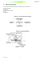
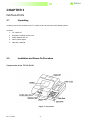
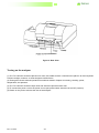
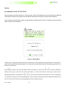
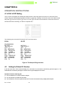
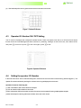
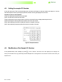
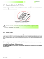
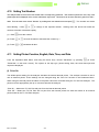
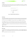
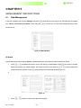
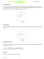
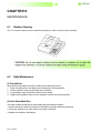
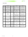
TC-720PLUS TC-720PLUS URINE ANALYZER Operator’s Manual Revision: 10/2007 Rev 02/2010 - 1- Copyright 2007 TC-720PLUS WARNING 1. Please read the User’s Guide before you operate this analyser. The power requirements comply with Part I of IEC61010-90. 2. Please contact the manufacturer if the analyser does not work properly. 3. Do not look at the optical light source at the opening of the strip placement without eye protection. 4. Do not remove any of the analyser covers without instruction from the manufacturer. 5. Do not touch any of the internal parts of the analyser without the manufacturer’s instruction to avoid any possible accidents 6. It is recommended that safety gloves are used when handling and reading urine specimen and test strips. 7. To perform daily cleaning, maintenance, and troubleshooting, safety gloves must be used. Detailed maintenance and precautions are described in Chapter 5. Rev 02/2010 - 2- TC-720PLUS Table of Contents Page 5 1. Introduction 2. System Overview 2.1 Specification 2.2 Measuring Principle 6 7 3. Installation 3.1 Unpacking 3.2 Installation and Power-on Procedure 3.3 Selection of Strip Type 4. Operation Instructions 4.1 Id ON / Id OFF Setting 4.2 Setting Patient Id ON /Id OFF 4.3 Operator ID ON / OFF Setting 4.4 Setting Operator ID Number 4.5 Setting Sample ID Number 4.6 Modification to Sample ID Number 4.7 Operation Methods of the TC-720 Plus 4.8 Testing A Strip 4.9 Setting Buzzer Volume 4.10 Setting Test Number 4.11 Setting the Printer Function, English, Date, Time, and Data (I) Print On (II) English (III) Setting the Date (IV) Setting the Time (V) Setting Data Input / Output (VI) Move (VII) Strips (VIII) Units 5. Management Instructions 5.1 Data Management (I) Search (II) Printing Data (III) Sending Data (IV) Comment (V) Setting Urine Color (VI) Time 9 9 13 14 15 15 15 16 16 17 17 18 19 19 19 20 20 20 20 21 21 21 22 22 23 24 24 24 24 6. Maintenance 6.1 Routine Cleaning 25 6.2 Daily Maintenance 25 (I) (II) Rev 02/2010 Test Platform Urine Strip Waste Box 25 25 - 3- TC-720PLUS 7. Error Messages & Troubleshooting (I) The Screen Does not Turn On 26 (II) The Thermal Printer Does not Print 26 (III) The TC-720 Plus Stops Testing 27 7.1 Error Codes 28 8. Data Communication Interface 8.1 Interfacing (I) 29 Serial Port 29 (II) Parallel Port 29 Appendix 1. Table of Results Rev 02/2010 - 4- 30 TC-720PLUS CHAPTER 1 INTRODUCTION The TC-720PLUS urine chemistry analyzer is a semi-automated analyzer for urine chemistry analysis. This analyser has been manufactured and developed with advanced technology using modern microprocessors, optics and electronics. The TC-720 PLUS uses testing technology utilising a cold-light source, integrating sphere, and modularised blocking systematical design which enhances the stability of the optical system. This system also automatically compensates for the influence of ambient and scattered light through the coordination of software and hardware. The TC-720PLUS can test for 11 parameters including Glucose (GLU), Urobilinogen (URO), Bilirubin (BIL), Ketones (KET), Specific Gravity (SG), Occult Blood (BLD), pH, Protein (PRO), Nitrite (NIT), Leukocytes (LEU), and Ascorbic Acid (AC) in 60 seconds. The TC-720PLUS can test the following Urige Test Strips: URS-2P URS-4S URS-7 URS-2K URS-5K URS-7L URS-3 URS-6 URS-8 URS-9 URS-10 URS-11 The TC-720PLUS has the following characteristics: LCD Touch screen Patient ID profile entry Automatically determines patient urine color RS-232 Interface Temperature indicated on the LCD display Easy to Maintain Run up to 500 tests / hour Contains internal waste tray 2000 tests memory Results searchable by date or Patient ID number Random Test Mode or Continuous Test Mode Marks abnormal results Primary and Secondary wavelength reading for automatic correction The analyzer is only compatible with the Syntron Bioresearch URS line of Urine Strips. If strips other than Syntron Bioresearch URS are used then results may be inaccurate. Rev 02/2010 - 5- TC-720PLUS CHAPTER 2 SYSTEM DESCRIPTION 2.1 System Overview Normal operational conditions (1) (2) (3) (4) Power adapter input:: Temperature: Humidity: Atmospheric pressure: 100-250VA/ 1.0A, 50-60Hz 10 – 30ºC 75% 70.0 – 106.0 Kpa Transportation conditions (1) Firmly pack in boxes using foam or appropriate packaging materials (2) Avoid moisture and keep upright. Specifications (1) (2) (3) (4) (5) (6) (7) (8) Optical measurement: cold light source Methods: testing the color change of the strip pads using dual wavelengths Measurement wavelengths: 525nm, 550nm, 620 nm, 720nm Throughput: up to 500 tests / hour Data storage: memory capacity of 2000 recent test results Printer: built-in thermal printer, external printer; ASCII RS232 Thermal Sensing Touch Screen: LCD 320 mm x 240 mm Test parameters: Glucose (GLU), Urobilinogen (URO), Bilirubin (BIL), Specific Gravity(S.G), occult blood (BLD), pH, Protein (PRO), Nitrite (NIT), Leukocytes (LEU), Ascorbic Acid (AC) (9) Physical dimension: 350mm x 380mm x 182mm (10)Net Weight: 10kg Rev 02/2010 - 6- TC-720PLUS 2.2 Measuring Principle The entire system is controlled by microprocessor chips and the major components are: A) Sampling component B) LCD Screen C) Motor operation components D) Printer E) Control Keys Diagram 1- Overall operational diagram Diagram 2- Sampling Diagram Rev 02/2010 - 7- TC-720PLUS The TC-720PLUS can determine the intensity of different colours on the reagent strip test area. It measures colour intensity by irradiating the test pad with white light and detecting the reflectance on the test pad with an integrated sphere photo-detector. This photo-detector is filtered to measured wavelengths of 525nm, 550nm, 620nm, and 720nm. 720nm is the reference wavelength and the combination of 525nm, 550nm and 620nm lights are to differentiate the color intensity. Results are calculated by a reflection rate (R%) which is a percentage of the total reflectance of the testing wavelength and are printed automatically. If the intensity of colour on the strip is high then the reflectance will be low conversely if the intensity of the colour is low then the reflectance will be high. Apart from there being strip blocks for each test there is also a reference block (blank) on the strips. Its function is to rectify any error that may be caused by the colour or the urine itself. The formula for reflectance is: Tm·Cs R(%)= Ts·Cm R: Reflectance Tm: The intensity of reflected radiation of the strip block to testing wavelength Ts: The intensity of reflected radiation of the strip block to reference wavelength Cm: The intensity of reflected radiation of the reference block to testing wavelength Cs: The intensity of reflected radiation of the reference block to reference wavelength Please read the TC-720 Plus-720 PLUS Operator’s Manual carefully before installation, to ensure proper operation of the analyser. Rev 02/2010 - 8- TC-720PLUS CHAPTER 3 INSTALLATION 3.1 Unpacking Carefully remove the contents of the TC-720PLUS box and check for the following items: Contents: 1. TC-720PLUS 2. European or British Power cord 3. Power Adapter 9V/ 4A 4. Roll of printer paper 5. Operator’s Manual 3.2 Installation and Power-On Procedure Components of the TC-720 PLUS Figure 1: Front View Rev 02/2010 - 9- TC-720PLUS Figure 2: Rear View Turning on the analyser (1) The TC-720PLUS should be placed on a clean, flat, stable surface. It should not be place in an area exposed to direct sunlight, moisture, or electromagnetic interferences. (2) Testing area should meet all operational conditions stated in Chapter 2 including, humidity, power, temperature, and pressure. (3) The TC-720PLUS should be kept clean and should be protected from dust. (4) To connect the power cord to the power source (the power switch should be in the OFF position). (5) Switch on the power switch at the rear of the analyser. Rev 02/2010 - 10- TC-720PLUS Set-Up (I) Installation of the TC-720 PLUS When the analyser has been switched on, it will go through a series of self diagnostic checks. During this time malfunction codes will show if there are any problems with the analyser. Please refer to the service manual for further assistance. Urine controls are recommended to verify the results against the ranges provided. If there is a deviation in the results, please report the result to technical support. Caution: Make sure that the current and voltage of the power supply is stable before use or the analyser may be damaged. Figure 3: Startup Menu If malfunction ‘9’ appears during the instruments initial set up, it is possible that the strip platform is not properly in place and has shifted during transportation or the strip rack may have been blocked. The following procedure can be used to resolve this. Press to enter into the main operational menu (see Figure 4), then press Setting, press or to enter into the menu (see Figure 7), then choose Move, press operational interface; and then press or to choose Parameter to enter into its to move the rack so that the test strip can be set for single-step or continuous movement; if the strip sending rack runs smoothly it indicates that the mechanical performance of the TC-720 PLUS is normal. Press Rev 02/2010 repeatedly to return to Start Up menu. - 11- TC-720PLUS Press the < Yes > button to display the Operational menu Caution: Do not disassemble the analyser while it is switched on, as this may cause damage. Figure 4: Operational Menu (II) Touch Screen Calibration The calibration procedure should be initiated before use. At the startup screen, press + finger, and touch each dot. Press the key to enter the operation menu. ‘Press this dot’ will blink. Use your index key to confirm and then to exit. (III) Changing Printer Paper CAUTION: Make sure the thermal paper is dry before installation. The printer will stop working if the thermal paper appears wet. The printer will not print if the wrong side of the thermal paper is inserted since it is coated on one side only. Do not run the printer without any thermal paper installed. The printer head may be damaged. Instructions for changing printer paper: Turn on the TC-720 PLUS; remove the printer cover by applying steady upward pressure to the rear of the cover. Secure the printer paper in the printer bed and place one end of the paper under the rubber wheel. Lift up the puller rod as in Figure 5 and rotate the printer Knob to engage the paper. Close the puller rod. Press to enter main menu screen. On the menu screen toggle (using arrows) to Paper Feed and press this will advance the paper. Make sure paper is advancing properly. Replace the cover making sure that the printer paper is placed through the slit on the cover. Rev 02/2010 - 12- , TC-720PLUS After changing paper make sure that the printer is working correctly by running a “test” strip. If there is no print output the paper may have been installed with the wrong side facing the printer. Repeat the above procedure and turning round the roll of paper. Diagram for Installation of Printer Paper Figure 5: Paper Setting 3.3 Selection of strip type From main menu select ‘Parameter’ and press to enter into its operational interface,Press to enter the operation menu. Scroll down to ‘Strips’ and press or keys to select strip type (URS-2K to URS-11). Press key to return to the previous menu to save changes. Test strips are disposable product and cannot be used more than once ATTENTION: 1) The analyser must be installed in a place where all safety requirements are met. 2) Regularly clean the analyser with soft tissue 3) SHAPE \* MERGEFORMAT Do not disassemble the analyser 4) Use clean containers for all urine samples 5) Use a fresh urine sample. 6) Concentrated urine samples must be diluted. 7) The test strip must be dipped completely into the urine. The dipping time must be strictly controlled at 2 seconds. 8) The analyser should be used at normal room temperature 9) Do not use any liquids to clean the touch screen. It must be cleaned using a dry soft CHAPTER 4 tissue or proprietary cleaning cloths Rev 02/2010 - 13- TC-720PLUS CHAPTER 4 OPERATION INSTRUCTIONS 4.1 Id ON / Id OFF Setting The TC-720 PLUS analyser has a sample ID number function. There is the option to turn this on or off from the Touch Screen. Enter the Data Management Menu interface by selecting “Manage” at the main menu, then Select ‘Id ON’ and press to turn off or press to turn on. Press to exit and to store selection. Ensure this function is switched ON before switching on Patient or Operator ID’s The following print outs with ID ON and ID OFF are shown below ID ON ID OFF ID=0000000001 NO 0001 Time 16:32:21 GLU 1+ BIL NEGATIVE KET NEGATIVE SG >=1.030 BLD NEGATIVE PH 5.0 PRO NEGATIVE URO 3.2umol/L NIT NEGATIVE LEU 2+ NO 0001 Time 16:32:21 GLU 1+ BIL NEGATIVE KET NEGATIVE SG >=1.030 BLD NEGATIVE PH 5.0 PRO NEGATIVE URO 3.2umol/L NIT NEGATIVE LEU 2+ Figure 6: The Sample ID Sign Interface 4.2 Setting the Patient I.D. Number In the main menu touch “Test” to enter the testing menu, and touch ‘PI’ on the screen to enter the key pad menu (figure 7). The Patient Number is entered by touching the numbers on the key pad displayed on the screen Operation Functions of the Key pad: (1) “Del” can delete the’ PI ‘number set into the analyser (2) “Clr” can clear the ‘PI’ number from the screen (3) “Yes” will enter the ’PI’ into the system and the next ‘PI’ can then be entered if running multiple patient samples Rev 02/2010 - 14- TC-720PLUS (4) “Quit” will escape from the key pad screen and back to the main menu screen Figure 7: Patient ID Screen 4.3 Operator I.D. Number ON / OFF Setting The TC-720 PLUS analyser has a sample ID number function. There is an option to turn this on or off for the Touch Screen function. Enter the Data Management Menu interface by selecting “Manage” at the main menu, then Select ‘Id ON’ and press to turn off or press to turn ON. Again, press to exit. Figure 8: Operator ID Screen 4.4 Setting the operator I.D. Number In the main menu touch “Test” to enter the testing menu, and touch the OI on the screen to enter the key pad menu (figure 7). The operator ID number is entered by touching the numbers on the key pad displayed on the screen. Operation Functions of the Key pad: (1) “Del” can delete the OID number set into the analyser (2) “Clr” can clear the OID number from the screen (3)“Yes” will enter the OID into the system and other OI numbers can be entered if running multiple patient samples (4)“Quit” will escape from the key pad screen and back to the main menu screen Rev 02/2010 - 15- TC-720PLUS 4.5 Setting the sample ‘ID’ Number In the main menu touch “Test” to enter the testing menu, and touch the ID place to enter the number menu (figure 9). You may enter the sample ID number by touching the patient ID numbers on the key pad displayed on the screen. Operation Functions of the Keyboard: (1)“Del” can delete the ID number set into the analyser (2)“Clr” can clear the ID number from the screen (3)“Yes” will enter the ID into the system and the next ID can be entered if running multiple patient samples at once (4)“Quit” will escape from the key pad screen and back to the main menu screen (5)“Up” will scroll through the number of patient ID’s set into a computer if connected (6)“Dn” will scroll through the previous patient ID’s set into a computer if connected Figure 9: Sample ID Interface 4.6 Modification of the Sample I.D. Number In the Operation Menu, touch “Manage” (or press ), touch “Search” and then touch the display at the sample ID. Here you can search for any previously entered sample ID’s to change the ID or remove it from the set of ID’s you expect to run. Rev 02/2010 - 16- TC-720PLUS 4.7 Operation Methods of the TC-720 Plus Once the analyser is turned on and the self diagnostics is complete. Press menu. Press to enter the main operational to enter previous menu. Figure 10: Correct Strip Loading Place the urine test strips in the rack position exactly as shown in figure 10 above to prevent the analyser from jamming. 4.8 Testing a Strip In the main menu, using the arrow keys select ‘test’ and press . At this time the analyser will beep a series of times. Dip the test strip into the urine for no more than 2 seconds making sure the urine comes into contact with all test pads. Blot the strip on an absorbent piece of paper and place on the strip rack ensuring the end of the strip just touches the back of the test board. A) Do not dip the urine strip in urine for too long as this may affect the results. B) After sampling, immediately place the urine test strip on the analyser test board. Delays may cause the test pads to darken giving false negative or highly abnormal results. C) The test strip is a consumable - do not attempt to reuse D) If a MALFUNCTION occurs during a test, check the trouble shooting section of the manual to fix the problem and rerun the test. Rev 02/2010 - 17- TC-720PLUS Figure 11: Pre results screen The test rack will begin to rotate and the strip will enter the analyser. At this time the analyser will again beep several times. Dip the next urine strip into the next sample, for 2 seconds, blot on absorbent paper to clean off excess urine and place in the next appropriate rack position on the analyser. After 5 seconds the analyser will beep again and the test strip will enter the analyser. The strip rack will move one position every 5 seconds and will move the strip along the strip carrier (conveyer belt) until it reaches the reading position after 60 seconds. The strip will then be read and the results will be printed. (1) Please read the instructions on how to handle Urine Reagent strips located in the package insert included with each bottle of Urine Reagent Strips. (2) The urine test strip is a one-use product and must only be used once. SPECIAL DIRECTIONS Do not move the analyser while a test is running. This will cause the analyser to malfunction. The TC-720 Plus analyser will begin to test the first test strip after 60 seconds and can test one test strip every 5 seconds thereafter. The analyser will automatically keep the data for all test results, and synchronously display and print these test results The analyser can continuously load strips with the conveyer belt test strip carrier. When the analyser is in test mode and is testing simply place a test strip in the next position to run a test. If testing is completed or the testing in process needs to be stopped, exit from the test status can be achieved by pressing and holding 4.9 for 2 seconds. The main operation menu will then be displayed. Setting the Buzzer Volume Buzzer volume can be changed by pressing: + = Will increase the volume + = will decrease the volume Rev 02/2010 - 18- TC-720PLUS 4.10 Setting Test Number The analyser holds a record of the test number that is currently being performed. This number is printed out on the top of the printed report and is displayed on the screen at the bottom right corner. This number can be set to start at any point from 0001 – 9999. From the main menu choose “Number” by scrolling down the selection arrow and press seen flashing. Press or . The number set will be to change to the required number. Holding down the arrows will make the numbers increase or decrease rapidly. (1) Press to set the number (2) Press or once will increase or decrease the number by 1. (3) Press + will delete all data 4.11 Setting Printer Function, English, Date, Time, and Data From the Operation Main Menu, and using the arrow keys, choose “Parameter” by pressing (or touch “Parameter” on the touch screen). The options to set strip type, printer setting, date, time and data input and output are displayed (I) Print On The default printer setting for the analyser activates the internal thermal printer. The analyser can also be set to use an external printer. These settings can be changed using the “Print On” function in the Parameter Menu. When using an external printer the status of the printer cannot be controlled using the TC-720 Plus analyser. The printer must be appropriately set up to communicate with the analyser. “Print On” – Means the TC-720 Plus will print from the internal thermal printer “Print Off” – Means the TC-720 Plus will not print from the internal printer but send the results to an external printer linked to the TC-720 Plus analyser Rev 02/2010 - 19- TC-720PLUS (II) English The default language setting for the TC-720 PLUS is English. The Standard Print format is as follows: No 0001 Date 2003-06-02 Time 17:25 GLU 500 BIL LARGE KET >= SG 1.025 BLD LARGE PH 7.5 PRO 100 URO >= NIT POSITIVE LEU LARGE mg/dl 80 mg/dl mg/dl 8.0 EU/dl Figure 12: Print Format To change the Units see section (V111) below (III) Setting the Date Choose “Date” in the Parameter Menu and press month, or day at the top left of the screen). The to shift between year, month, or day (or touch the year, or buttons will increase or decrease the date selected. You may also use the key pad shown on the screen to set the number of the year, month or day. (IV) Setting the Time Choose “Time” in the Parameter Menu and press minute or second at the top of the screen). The to shift between hour, minute or second (or touch the hour, or will increase or decrease the time parameter selected. You may also use the key pad shown on the screen to set the number of the hour, minute or second. (V) Setting the Data Input / Output In the Parameter Menu choose “Baud Rate” using the arrow keys and then press . By using the arrow keys you can choose different “Baud Rates” (300, 600, 900, 1200, 4800, 9600, 19200, 38400, 57600, 115200). Pressing after the “Baud Rate” has been set the system will return to the Parameter Menu. Rev 02/2010 - 20- TC-720PLUS (VI) Move The “Move” item in the TC-720 PLUS menu is used in TC-720 PLUS maintenance. Choose “Move” in “Parameter” menu and press and enter into its operational menu (Figure 13) where control of the running conditions of each motor using the keypad can be carried out. Figure 13: Operational Interface in Motor drive (VII) Strips The TC-720PLUS maintains a record of each test number. This number is printed out on the top of the report and is displayed on the screen in the bottom right corner. This number can be set to start at any point between1-0999. From the main menu choose “Parameter” by scrolling the selection arrow to “Parameter” and pressing Choose “Strips” in this menu. The number setting will flash. Using the or . arrows change the flashing number as required. Holding down the arrows will make the numbers increase or decrease in increments of 10. Press to return to the Main menu. The first test will start at the number set by the user. Each test after this will increase by one from the set point. When a new start number is set the data saved on previous numbers will be overwritten by the new data and lost. (VIII) Units To change the units in the analyser, from the Main Menu screen hold down and press to change from C1 C2 S1 S2. The Units are displayed in the bottom left corner of the screen next to the Temperature reading of the analyser. NOTE: Conventional and SI Units are shown on pages 30 and 31 Rev 02/2010 - 21- TC-720PLUS CHAPTER 5 MANAGEMENT INSTRUCTIONS 5.1 Data Management In the main operation menu choose “Manage” and press from “Search, Print, Send, & Comment”. Note: every time to enter into the menu (Figure 14), Test data can be managed is pressed, the TC-720 PLUS analyser will return to the previous menu, Figure 14: Manage Menu (I) Search Specific data can be found using the “Search” operational interface. There are three search methods as follows: Press + simultaneously and the year in the date (e.g. 2008) flashes. Press flashes. By pressing switch between ‘Year’ ‘Month’ and ‘Day’, then press key required for search purposes. Press Figure 15 Press Rev 02/2010 + or and the Number for the test data will flash (Figure 15). , the month in the date to set the number for the data that is required. - 22- to set the date that is TC-720PLUS Press + simultaneously, and then press or to view all test data on the displayed date of the TC-720 PLUS analyser. If there is no test data on the requested date, the analyser will display no data. (See Figure 16) Figure 16 (II) Printing Data If printed data is required print the data from the “Search” operational interface press ‘Print’ on the top right of the screen or press to go back to the “Manage” menu. Choose “Print Data” to enter the operational menu. Select printing requirements by pressing or , and choose the sample ID number and then press Figure 17 Rev 02/2010 - 23- ,. TC-720PLUS (III) Sending Data The TC-720 PLUS analyser can send selected test data to a computer after using the search function. Press to go back to the management menu and choose “Send” to enter into the operational interface (Figure 18). Data to be sent can be selected by pressing or . Press , to send the data to a computer Figure 18 (IV) Comment Choose “Comment” in the management menu and press (Figure 19) . The screen will display the technical information for the analyser Figure 19 (V) Setting Urine Color The analyser can detect urine color when the printer is set to print urine color. Enter the Data Management Menu to set “Color On” or “Color Off.” “Color On” – Means that the color will print on all results “Color Off” – Means that the color will not print on all results (VI) Time Adjust hour, minute and second in the “Time” menu. Rev 02/2010 - 24- TC-720PLUS CHAPTER 6 MAINTENANCE 6.1 Routine Cleaning The TC 720 plus analyser must be maintained properly in order to insure proper operation. CAUTION: Do not use organic solutions such as alcohol, or acetone, etc to clean the reagent strip assembly. It must be cleaned and wiped using soft tissues or gauze. 6.2 Daily Maintenance (I) Test platform Clean the urine strip platform everyday according to the following procedure: 1. Switch off mains power to the analyser and carefully pull out the test platform. 2. Clean the platform using only clean water and a soft tissue. 3. Dry the platform using a dry tissue or allow it to dry naturally. 4. Replace the test platform and turn on the analyser to ensure it is functioning properly. (II) Urine Strip Waste Box The waste container should also be cleaned daily using the following procedure: 1. Remove the waste container and dispose of used strips according to laboratory procedures. 2. Thoroughly wash the box in clean water and dry using a soft tissue. 3. Replace the container in the analyser. Rev 02/2010 - 25- TC-720PLUS CHAPTER 7 ERROR MESSAGES and TROUBLESHOOTING The following is a short guide to troubleshooting problems associated with the TC-720PLUS analyser. If there is a malfunction and an error code is displayed please refer to the table below. If there are problems with the analyser that are not covered in this section or if this guide does not cure the problem please contact the manufacturer or distributor. Do not attempt to repair the analyser without guidance of the distributor or manufacturer. (I) Screen does not turn on A. The screen may have no display if the back light is not properly set. Press and hold , then use or to adjust the brightness of screen. B. If the power requirements are not to specification as outlined in this manual, or if the power is not connected correctly the analyser will not turn on. Make sure that the power requirements are met and that the power connections are secure. C. Check whether the fuses at the back of the TC-720 PLUS analyser are still functional. (II) The thermal printer does not work. A. Make sure the thermal printer has paper. B. Make sure the printer paper is installed correctly. If the paper is installed with the wrong side facing the thermal heads then the printer will not print. Reinstall the paper with the reverse side facing the heads. C If the reflecting pole of the thermal printer is dirty, then the printer will not work properly. Clean the reflecting pole with a soft tissue. D. Make sure that the printer is set to print. This is done from the “Parameter” menu and the printer setting should be set to “Print On” CAUTION: Do not open up the analyser and remove any of its parts other than what is mentioned above or damage to the analyser may be caused. Rev 02/2010 - 26- TC-720PLUS (III) The TC-720 PLUS Analyser Stops Testing If the TC-720 Plus analyser stops during testing switch the analyser off immediately. Open the front cover by hand to view the test strip platform. The strip platform may have acquired some debris or test strips may have become jammed causing the conveyer belt to stop moving. Remove any debris or strips stuck in the conveyer belt. When cleared of all debris or obstructions enter the Main Operational Menu and enter the Parameter Menu. From here choose “Parameter Setting” and then “Move.” Use the keys to move the rack. If the rack moves smoothly it indicates that the mechanical performance of the apparatus is normal. Press Rev 02/2010 - 27- to return to the main operation menu. TC-720PLUS Error Codes ERROR code Description TC-720 PLUS status Reason Solution Error 0 (Wrong E-PROM Data) Off Status Wrong E-PROM Data Contact Supplier Error 1 (Light too bright) Off Status Optical system requires attention Contact Supplier Error 3 (Improper Strip placement) Testing not carried out Misplaced strip Optical system needs attention Error 4 (Weak light response) Error 7 (Incorrect strip type) Error 8 (Will not test continually) Error 9 Error B Rev 02/2010 (Motor limitation control is lost) (Incorrect Test Strip type selected) Off status Pause status Off Status The TC-720 PLUS will not process samples The TC-720 PLUS will not process samples - 28- Abnormal sample color Misplaced strip Dirty test board Incorrect strip type Strip color is too dark The TC-720 PLUS requires service repair The test platform is fouled with debris or test strips Error Code 6 continually appears Replace the test strip correctly Contact Supplier Replace the sample and repeat the test Replace the strip correctly Clean the test platform Use correct strip type Verify the voltage of power supply Clean the test platform Resolve previous malfunctions Incorrect test platform position Reposition of the test platform Test strip is not recognized by the analyser Use the test strip type that has been programmed into the analyser TC-720PLUS CHAPTER 8 DATA COMMUNICATION INTERFACE 8.1 Interfacing The TC-720 PLUS can transmit data through the RS232 interface port at the rear. Connection to a computer can be made by using the appropriate cable available from the manufacturer. Follow the directions below to connect to an external computer: (I) Serial Port Serial interface output: Standard RS232 level signal Data code: Output time: Results transmitted after printing Output format: 4800 baud rate, data 7 figures, stop 2,even Output loop: photoelectric ionization. ASCII Standard 9 pin computer tandem outlet should be used for the tandem outlet cable. “2” pins are for the Output signal; “3” are for the Input signal and 5 pins are ground. (II) Parallel port: Standard 25 pin parallel printer interface. Rev 02/2010 - 29- TC-720PLUS Appendix 1 TABLE of RESULTS (1) CONVENTIONAL UNITS Rev 02/2010 - 30- TC-720PLUS TABLE of RESULTS (2) S I UNITS Rev 02/2010 - 31-