1
Checked:
Date:
SGJ
June 2012
FHPP
•
Installation of the new circulating pumps on the temporary chiller chilled water pipework.
•
Installation of the new electrical connections for the temporary chiller
•
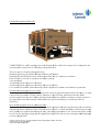
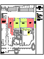
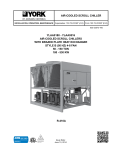
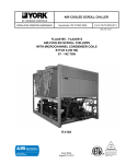
Installation of the 250 kW Johnson Controls (YORK) air cooled chiller externally in the
location shown on the tender drawing, further described in Section 5.00
•
Installation of the new controls including electrical works in connection.
Temporary chilled water pipework and circulating pumps
At this stage of the works the Contractor is to complete the installation of the modified buffer vessels
chilled water pipework that reconnects the new circulating pump with the existing buffer vessel flow
connection and the new modified connections on the low loss header. The Contractor is to allow for
the installation of all associated valves as detailed on the tender drawings and in line with the valve
schedule. The existing cable tray that runs alongside the mezzanine level is to be removed and the
cables located on this tray are to be repositioned to the adjacent tray. This would enable the buffer
vessels chiller chilled water pipework to be routed to and from the mezzanine level.
New connections for the temporary chiller chilled water shall be installed on the buffer vessels flow
chilled water pipework alongside a new fully lugged butterfly type isolating valve.
The return chilled water pipework from the buffer vessels shall be reconnected to the prepared
connection on the low loss header.
The new buffer vessel connections from the low loss header shall be interconnected with the
existing flow and return connections son the buffer vessels will remain operational once the
temporary chiller is not working.
Once the connections are completed the Contractor shall allow for interconnection of the temporary
chiller chilled water pipework with the new connections on the buffer vessels connection side.
Within the generator room the Contractor is to create the builders work openings through the
generator wall louvres for the temporary chiller flow and return pipework and the electrical
connections. The builders works are described in further detail under the Builders work Section
8.00. The chilled water flow and return pipework shall have flanges provided on internal side of the
louvre wall to enable easy maintenance and disconnection. The connections are to be provided with
blanked flanges within the generator plantroom until the temporary chiller is delivered on site.
Temporary chiller
The Contractor is to closely liaise with the temporary chiller manufacturer (Johnson Controls YORK) on the delivery date of the temporary chiller so its installation is scheduled within the
enabling package scope of works. Once the temporary chiller is delivered on site and positioned, the
Contractor is to extend the temporary chiller chilled water flow and return connections and connect
the temporary chiller to the system with all associated valves. A detailed description of the chiller
and its controls can be found in Section 5.00 and 7.00. The pipework is to run externally on a
suitably sized galvanised tray supported from the filed external surface on “duck-foot” supports.
Electrical works
The electrical contractor shall be responsible for installing a 315 Amp TP&N isolator within the
generator room for connection of the temporary chiller. This shall be located adjacent to the
northerly facing acoustic louvres, mounted directly to the wall.
Y:\00-Enquires\E4340\4.0 FHP Specifications\4.8 Combined M&E\E4340 M&E Technical Specification.docx
25