1
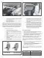
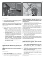
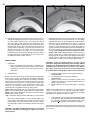
1
S&S Cycle, Inc.
Instruction No. 51-1124
Revised 3-5-02
14025 County Highway G P.O. Box 215
Viola, Wisconsin 54664
Copyright®, 2002
Phone: 608-627-1497 • Fax: 608-627-1488
by S&S Cycle, Inc.
All rights reserved. Printed in the U.S.A.
®
Technical Service Phone: 608-627-TECH (8324)
Technical Service Email: [email protected]
Because every industry has a leader
Assembly and Installation Instructions
for S&S Super Sidewinder Plus Style Long Block
Safe Installation and Operation Rules:
Important Notice:
● Before finishing and installing your S&S Long Block, it is your
responsibility to read and follow the installation and maintenance
procedures in these instructions and to follow the basic rules below for
your personal safety.
Statements in this instruction sheet preceded by the following words are
of special significance:
WARNING
Means there is the possibility of injury to yourself or others.
● Gasoline is extremely flammable and explosive under certain
conditions, and the fumes toxic when inhaled. Do not smoke around
gasoline. Perform the installation in a well-ventilated area away from
open flames or sparks.
● Compressed air and particles dislodged by compressed air are harmful
to eyes and body. Wear protective goggles when using compressed air
and always direct the air stream away from your eyes and body and
other people nearby.
● Some solvents, degreasers and other chemicals are harmful,
especially to skin and eyes. Many chemical compounds such as lacquer
thinner are also flammable and present a fire hazard. Read the
manufacturer’s instruction label for precautions and proper use. Use in
a well ventilated area and wear protective clothing to avoid personal
injury.
● If the motorcycle has been running, wait until the engine and exhaust
pipes have cooled before performing any installation steps to avoid
getting burned.
● Before performing any installation steps, disconnect and remove the
battery to eliminate potential sparks and inadvertent engagement of
the starter while working on the motorcycle.
● Read instructions thoroughly and carefully so all procedures are
completely understood before performing any installation steps. Contact
S&S if you have questions, if any steps are unclear, or if any
abnormalities occur during final assembly, installation, or operation.
● Contact an authorized H-D service manual for correct disassembly,
reassembly, and installation procedures for any parts that need to be
removed to facilitate the installation.
● Use good judgment during assembly, installation, and when operating
the motorcycle. Good judgment begins with a clear head. Don’t let
alcohol, drugs, or fatigue impair judgment. Perform the assembly and
installation when fresh.
● For optimum performance and safety and to minimize potential
damage to the Long Block or other components, use correct hardware
and follow procedures outlined in S&S instructions and an authorized
H-D service manual.
● Be sure all oil and fuel lines are routed correctly with clamps in place
and tightened. Lines must not contact exhaust pipes or other hot surfaces
where they could melt or leak and catch fire.
● Motorcycle exhaust fumes are toxic and must not be inhaled. Run
motorcycle only in a well ventilated area where fumes can dissipate.
● S&S Long Blocks are substantially more powerful than the stock
engines they often replace. It is the sole and exclusive responsibility of
the user to determine the suitability of the product for his or her use.
The user shall assume all legal, personal injury risk and liability and all
other obligations, duties and risks associated therewith. S&S parts are
intended for experienced riders only.
CAUTION
Means there is the possibility of damage to the motorcycle or a
component.
NOTE
Other information of particular importance has been placed in italic type.
S&S urges you to take special notice of these advisories.
Warranty:
All S&S parts are guaranteed to the original purchaser to be free of
manufacturing defects in materials and workmanship for a period of twelve
(12) months from the date of purchase. Merchandise that fails to conform
to these conditions will be repaired or replaced at S&S’s option if the
parts are returned to S&S by the purchaser within the 12 month warranty
period or within 10 days thereafter. In the event warranty service is
required, the original purchaser must notify S&S of the problem
immediately. Some problems can be rectified by a telephone call and
need no further action. A part that is suspected of being defective must
not be replaced without prior authorization from S&S. If it is deemed
necessary for S&S to make an evaluation to determine whether the part
was defective, it must be packaged properly to avoid further damage,
and be returned prepaid to S&S with a copy of the original invoice of
purchase and a detailed letter outlining the nature of the problem, how
the part was used, and the circumstances at the time of failure. If after
an evaluation was made by S&S and the part was found to be defective,
repair, replacement, or refund will be granted.
Additional Warranty Provisions:
(1) No part shall be returned to S&S without first contacting the company
and obtaining a Return Authorization (RA) number.
(2) S&S shall have no obligation in the event an S&S part is modified by
any other person or organization, or if another manufacturer’s part is
substituted for one provided by S&S.
(3) S&S shall have no obligation if an S&S part becomes defective in
whole or in part as a result of improper installation, improper break-in or
maintenance, improper use, abnormal operation, or any other misuse or
mistreatment.
(4) S&S shall not be liable for any consequential or incidental damages
resulting from the failure of an S&S part, the breech of any warranties,
the failure to deliver, delay in delivery, delivery in non-conforming
condition, or for any other breach of contract or duty between S&S and a
customer.
(5) S&S parts are designed exclusively for use on Harley-Davidson
motorcycles. S&S shall have no warranty or liability obligation if an S&S
part is used in any other application.
2
INTRODUCTION
Super Sidewinder-Plus Long Block Instructions often refer to
procedures described in other S&S instructions or a HarleyDavidson Service Manual. These materials should be crossreferenced as necessary.
All Super Sidewinder-Plus Long Blocks are designed for frames
that accept Harley-Davidson Evolution Big Twin engines, and will
fit stock H-D and similar frames without modification.
S&S strongly recommends trial-fitting every engine before frame
is painted or powder coated.
Because the Super Sidewinder-Plus crankcase is 1⁄4 inch wider
than stock, fit of exhaust, rear brake master cylinder, and foot
controls must be closely checked when installing the Super
Sidewinder Plus Long Block. Some components may require
modification.
WARNING - In some instances, brake master cylinder must
be spaced out from frame to clear crankcase. UNDER NO
CIRCUMSTANCES SHOULD MASTER CYLINDER OR BRAKE
LINE BE ALLOWED TO CONTACT EXHAUST PIPE IN FINAL
INSTALLATION. Heat transferred to brake fluid may expand
and cause brakes to seize, resulting in possible fire hazard
and loss of control of motorcycle with injury or death to rider
and others.
IMPORTANT NOTES
● Lubrication - S&S supplies Torco Engine Assembly Lube with
each Long Block. It should be used as specified in following
instructions. While other brands of assembly lube are acceptable,
other lubricants are not. In no instance should an aerosol lubricant
be substituted for assembly lube.
● Engine tuning - Ignition timing and carburetor jetting are
responsibilities of the customer. If not thoroughly familiar with these
procedures, he should contact a professional mechanic.
CAUTION - Incorrect ignition or carburetor tuning can cause
extensive engine damage not covered under warranty.
● Powder coating and polishing - While S&S does manufacture
some powdercoated Long Blocks, it does not recommend having
engine parts powdercoated or otherwise modified elsewhere. Many
such procedures leave abrasive residues which are difficult to
remove completely. Also, powder coating is cured at high
temperatures that can change the strength characteristics of some
metals.
Pinion Bearing Roller Diameter
Bearing Color Code
Roller Size
Total
Green
S&S 31-4016
.2502"
.5004"
H-D 24628-87A
White
S&S #31-4005
.2503"
.5006"
HD #24626-87A
Blue
S&S #31-4018
.2504"
.5008"
HD #24643-87A
Red
S&S #31-4017
.2505"
.5010"
HD #24628-87A
CAUTION - Glass bead and polishing residues are abrasive
and can be difficult to remove from recesses and small
passages. Abrasive residues can cause oil contamination and
extensive engine damage. Engine damage caused by powder
coating, polishing, glass bead blasting, or other modification
will not be covered under warranty.
ASSEMBLY
NOTE - While S&S has made every effort to insure that parts are
correct, it is the engine builder’s responsibility to confirm fit and
finish of all parts provided with Long Blocks prior to assembly.
Parts are deburred at S&S and usually require no further
preparation, but must also be inspected by installer. Individual parts
should not be removed from protective plastic wrappers until
needed. After removal from plastic, it is imperative that parts be
thoroughly cleaned and dried, preferably with compressed air.
When present, rust preventative must be completely removed.
Additionally, gaskets must be closely inspected for particles that
could become dislodged and damage engine. If assembly of Long
Block must be interrupted, seal openings and cover engine with
plastic to protect from destructive contaminants.
CAUTION - Failure to observe the above may result in
engine damage not covered under warranty.
S&S Pinion Shaft Main Bearing Fitting Charts
Chart 1
BT Bearing
Race Diameter
1.7511
to
1.7513
1.7509
to
1.7511
1.7507
to
1.7509
Chart 2
Pinion Shaft Bearing Diameter
1.2498-1.2500
Red
S&S #31-4017
HD #24628-87A
Blue
S&S #31-4018
HD #24643-87A
White
S&S #31-4005
HD #24626-87A
1.2500-1.2502
Blue
S&S #31-4018
HD #24643-87A
White
S&S #31-4005
HD #24626-87A
Green
S&S #31-4016
HD #24628-87A
Bearing Race Diameter
Minus Pinion Shaft
Bearing Diameter
.5005 to .5009
.5007 to .5011
.5009 to .5013
.5011 to .5015
Bearing Color Code
Green
White
Blue
Red
S&S #31-4016
HD #24628-87A
S&S #31-4005
HD #24626-87A
S&S #31-4018
HD #24643-87A
S&S #31-4017
HD #24641-87A
3
Picture 1
Picture 2
Confirm pinion shaft main bearing fit. Correct size bearing is
supplied with engine, but must be verified by engine builder.
Flywheel assembly can then be prepared for installation.
EXAMPLE - Pinion bearing race inside diameter is 1.7510". Pinion
shaft bearing surface diameter is 1.2499". 1.7510" minus 1.2499"
is .5011". Difference of .5011" splits .5009" to .5013" range in third
row exactly. Corresponding "BLUE" color code in right column
should be used. Notice that .5011" fits in several range groups.
Try to select group where difference falls closest to middle of range.
If you are not sure, select color that corresponds with group closer
to top of chart. This will provide slightly looser bearing fit and help
prevent bearing seizure. Selecting next color up on chart may also
be done if looser fit is desired for competition applications.
FLYWHEELS
NOTES
● Refer to information tag on crankcases for final honed size of
pinion shaft main bearing race.
● S&S pinion shaft main bearing fitting charts #1 and #2 use H-D
bearing color codes.
● All measurements must be taken with parts at room
temperature, approximately 70° F.
1.
Fitment Method A - Use Chart 1.
a. Refer to information tag on crankcases to determine final
honed size of inside diameter of pinion shaft main bearing
race.
b. Measure pinion shaft bearing surface diameter.
c. Cross reference pinion race inside diameter with pinion
shaft bearing surface outside diameter to determine
correct color code.
EXAMPLE - Pinion shaft bearing surface diameter measures
1.2499" and is between 1.2498" and 1.2500" in left "Pinion Shaft
Bearing Diameter" column. Pinion bearing race inside diameter is
1.7510" and falls between 1.7509" and 1.7511" in middle "Bearing
Race Diameter" column. Correct bearing color code where two
columns intersect is "BLUE". Selecting color where columns
intersect provides proper fit for normal service. If looser fit is
desired, select bearing color directly to right of color indicated from
selection process. If color indicated from selection process is
located in right color column, go to next row directly below and
select color in left color column.
2.
Fitment Method B - Use Chart 2.
a. Refer to information tag on crankcases to determine final
honed size of inside diameter of pinion shaft main bearing
race.
b. Measure pinion shaft bearing surface diameter.
c. Subtract pinion shaft bearing surface diameter from pinion
bearing race inside diameter.
d. Select range in left "Bearing Race Diameter minus Pinion
Shaft Bearing Diameter" column where difference best
splits high and low parameters of range. Corresponding
color bearing set in right "Bearing Color Code" column
provides proper fit for regular service.
CRANKCASES
NOTE - S&S crankcases are sold in matched sets only. Individual
case halves are not available.
1.
2.
Disassemble crankcases & wash in hot, soapy water. Rinse
case halves and blow dry with compressed air. Check all
internal passages. Coat bearing surfaces with a light oil to
prevent rust.
Install piston oilers – right-side crankcase.
a. Lubricate o-ring with engine oil and install in piston oiler.
b. Apply Loctite 243 to screws. Install oilers, tighten screws
to 25 in-lbs. See Picture 1.
INSTALL FLYWHEELS IN CRANKCASE
1.
Thoroughly clean parts according to instructions previously
mentioned. Apply coat of assembly lube to bearing surface of
sprocket shaft and inner race of Timken bearing. Install bearing
on shaft with appropriate tool. See Picture 2.
NOTE - S&S does not recommend using a press to install sprocket
shaft bearings, as this can push flywheels out of true. Correct
bearing installation tools are available from Harley-Davidson, Jim’s
Machine, and other sources.
4
Picture 3
2.
3.
4.
5.
Apply coat of assembly lube to Timken bearing installed in Step 1.
Place left side crankcase half on sprocket shaft and bearing,
insuring that connecting rods are in correct positions.
See Picture 3.
Install included Timken bearing spacer. See Picture 4.
Lubricate rollers of remaining Timken bearing with assembly
lube. Apply assembly lube to bearing inner race and sprocket
shaft bearing surface. Install bearing on shaft with appropriate
tool. See Picture 5.
NOTE - Pinion and sprocket shaft bearings should be correct sizes,
but it is engine builder’s responsibility to confirm flywheel endplay,
connecting rod sideplay, bearing fit, and all clearances in
Unassembled Long Block at time of assembly. It is of particular
importance to check flywheel endplay and install different Timken
bearing spacer if necessary. The flywheel end-play specification
is .001"-.005".
6.
Lubricate pinion bearing and pinion shaft bearing boss with
assembly lube. Install bearing and secure with pinion shaft
main bearing snap ring. See Picture 6.
NOTE - Snap ring supplied by S&S or identical replacement must
be used with pinion bearing supplied in Super Sidewinder-Plus
Long Block. Ends of snap ring are rounded on one side, sharp on
the other. Install snap ring with sharp edge out, away from
flywheels.
Picture 4
ASSEMBLE CRANKCASE HALVES
1.
Noting solvent precautions on page 1, wipe down mating
surfaces of crankcase halves with lacquer thinner. Remove
residue with clean, dry cloth, then apply sealant of choice to
both crankcase halves. Take care to avoid breather cavity and
other areas where sealant might reach inside of engine. See
Picture 7. Coat right main bearing race with assembly lube.
If applicable, allow sealant to cure according to manufacturer’s
instructions, then join left and right crankcase halves.
NOTE - S&S uses Threebond 1104 to seal crankcase. Use any
sealant carefully to prevent excess from entering engine and
obstructing oil passages or contaminating oil supply.
2.
Install crankcase studs and washers according to crankcase
instructions.
NOTE - Alignment studs for S&S crankcases are in locations B, E,
& G. See Diagram 1. They must be installed before other studs
and bolts. Fit is tight, so alignment studs must be lubricated with
assembly lube, then tapped through case assembly with plastic
mallet.
3.
4.
Tighten 5⁄16" case bolts and studs to 18 ft-lbs,1⁄4" center bolt to
120 in-lbs. See Diagram 1 for identification, and tighten
fasteners in following sequence: G-B-E-F-H-D-C-A.
Install drive sprocket spacer and sprocket shaft oil seal in
main bearing race of left case.
A
B
H
C
D
G
E
F
Picture 5
Diagram 1
5
Picture 6
NOTE - Because of sealed, wet primary in Evolution-style drive
trains, S&S installs sprocket shaft seals with spring facing out.
See Picture 8.
5.
Allow crankcase sealant to cure per mfr.’s instructions, then
pour four ounces of motor oil over bearing end of connecting
rod assembly and into flywheel cavity. Rotate flywheels several
times to distribute oil over connecting rod bearings. Assembly
should turn freely and without binding.
Picture 7
CAUTION - Routing oil supply line to lowest fitting on
models with oil tank below transmission could allow air
to enter oil pump under certain circumstances, causing
“air lock”, loss of lubrication and engine damage.
3.
Apply assembly lube to oil pump driveshaft and driveshaft
bushing in crankcase. See Picture 10. Install oil pump in
normal fashion, placing pump drive gear #33-4230 over
driveshaft as shaft is passed through crankcase bushing.
INSTALL OIL PUMP
1.
2.
Disassemble, clean and inspect oil pump, leaving supply drive
gear, key, and snap ring in place on shaft.
Reassemble pump, applying assembly lube to gears and gear
cavities in pump body. Remove excess to avoid contaminating
gaskets. Rotate gears as preliminary check for bind, and to
confirm that drive gear keys are properly installed.
NOTE - If bind occurs, determine whether problem is with supply
or return gears by removing idler gear from either side and rotating
pump. When binding gear is removed, pump will rotate freely.
Problem can usually be corrected by rotating gear 180°.
NOTE - S&S HVHP oil pumps offer more than one location for oil
supply fitting. Lowest fitting should not be used on Dynas, late
FL’s, or other models with oil tank below transmission. S&S
recommends stock placement for oil supply fitting in Dynas and
late FL’s. See Picture 9.
Picture 9
Picture 8
Picture 10
6
Correct
Incorrect
Picture 11
NOTE - A dab of Hylomar or other thin gasket sealer in corners
may be used to hold gaskets in place. Otherwise gaskets should
be installed dry.
4.
CAUTION - Loss of oil pump drive gear snap ring or key will
result in disengagement of oil pump causing loss of oil
pressure and extensive engine damage.
6.
7.
INSTALL PINION GEAR, SPACER & NUT
1.
Install driveshaft gear key and snap ring.
NOTE - Be sure drive shaft key and snap ring are installed properly,
paying particular attention to snap ring. If not installed correctly,
“sprung,” or otherwise damaged, snap ring may come off or allow
gear key to come out. See Pictures 11 & 12.
5.
Picture 12
Loosely install 2 each 1⁄4 -20 x 11⁄2” top oil pump bolts, followed
by pump cover and 4 each 1⁄4 -20 x 21⁄2” mounting bolts. Do not
tighten at this time.
While turning oil pump drive gear to check pump for binding,
gradually tighten 4 – 2 1⁄ 2” bolts in an X-pattern to final
specifications of 120 in-lbs. See Picture 13. Carefully tighten
short bolts “by feel” with thin box end wrench, or preferably
with a torque adapter, and tighten to 110 in-lbs.
Prime pump by removing oil pump check valve ball assembly
and injecting clean motor oil into pump supply fitting while
turning oil pump drive gear. (A large plastic squeeze bottle
works well for priming pump.) Replace check ball, spring,
and cap after oil fills check valve cavity.
Picture 13
With chamfer on oil pump drive gear facing in towards shoulder
on pinion shaft (See Picture 14), install oil pump drive gear
and key on pinion shaft, followed by drive gear spacer.
CAUTION - Installing gear backwards can result in a stress
riser and cause shaft to break.
2.
Apply red Loctite #272 to pinion gear nut threads. Install pinion
gear, key and nut on pinion shaft and tighten nut to 50 ft-lbs.
See Picture 15.
NOTE - Drive gear spacer will not completely fill space between
oil pump drive gear and pinion gear. A gap of up to .125” will exist
and is normal. Engine rotation keeps oil pump gear in place during
normal operation. Spacer prevents gear and key from becoming
disengaged if engine is rotated backwards.
CAUTION - Installing pinion gear or nut without Loctite can
cause damage to shaft, nut, or other parts.
INSTALL BREATHER GEAR, CAMSHAFT, AND GEAR COVER
Picture 14
7
Picture 15
Picture 16
4.
1.
2.
3.
Thoroughly clean and dry all parts including camshaft
lockwasher and thrust washer. Carefully inspect breather gear
for burrs and remove as necessary. Inspect edges of
crankshaft breather “window” for burrs and smoothness. Cam
thrust washer and breather gear shims should be correct size,
but endplay of camshaft and breather gear must be verified
by customer.
a. Breather gear end-play should be between .005” - .015”.
Install breather gear with supplied spacer into the breather
bore of the gearcase. With a new, uncrushed gasket
installed on the gearcase, use a straight-edge and
measure the distance to the spacer. Subtract .006”-.007”
for gasket crush, and this will be the breather gear endplay. Select correct thrust washer to achieve proper endplay.
b. Camshaft end-play should be .005” - .015”. Install
camshaft, with lockwasher and thrust washer, into cam
bearing. Install gearcase cover with new gasket and
tighten all fasteners to 120 in-lbs. Measure camshaft endplay with a feeler gauge or dial indicator at four different
positions of crankshaft rotation. Select correct thrust
washer to achieve proper end-play.
Apply light coat of assembly lube to cam bearing, camshaft
lockwasher, thrust washer, breather gear, and to breather gear
cavity inside engine, and coat of motor oil to cam lobes.
Place camshaft lockwasher in case with ears down and flat
edge towards rear of engine. See Picture 16.
Picture 17
5.
7.
8.
9.
Install thrust washer over end of cam and place assembly in
engine. During installation, rotate engine so marks on cam
gear and pinion gear align. Second mark on cam gear must
be at eight o’clock position.
Install breather gear and shim, aligning breather gear timing
mark with mark at eight o’clock on cam gear. See Picture 17.
Use connecting rods to rotate flywheels and insure gears rotate
freely. Apply assembly lube to ends of shafts and meshing
surfaces of gears and remove excess.
Apply assembly lube to gear cover bushings.
Install gasket and cover and tighten screws to 120 in-lbs.
NOTE - Gear cover should slide smoothly over alignment
dowels and must not be forced. Confirm that gasket material
does not overlap oil passages in crankcase and gear cover.
See Picture 18.
CAUTION - Having to force gear cover indicates an alignment
problem. Problem must be identified and corrected before
operating engine. Operating engine with forced gear cover
could result in broken pinion shaft or other engine damage.
10. Rotate flywheels to check for binding. If present, cause of
bind must be determined and corrected. If assembly rotates
freely, pour approximately four ounces of oil into gear
compartment after allowing crankcase sealant to cure per
manufacturer’s instructions.
Picture 18
8
Picture 19
Picture 20
INSTALL LIFTERS AND LIFTER GUIDES
INSTALL PISTONS AND CYLINDERS
NOTE - S&S installs HL2T (Hydraulic Lifter Limited Travel) kit in
lifters in assembled and unassembled Super Sidewinder-Plus Long
Block engines.
1.
Install V2 Style lifters and guides as follows:
1. If installed, remove oil pressure sending unit behind rear lifter
guide opening.
2. Identify gaskets for front and rear lifter guides. Gaskets are
not interchangeable.
3. Coat lifter guide bores with assembly lube and insert lifters.
Work lifters back and forth in guides, assuring that they move
freely and without binding. Apply engine oil to lifter rollers and
remove any excess.
4. Thoroughly clean and dry gasket surfaces of lifter guides and
crankcase. Place rear gasket on crankcase, assuring that oil
hole in gasket aligns with passage in case.
5. Taking care not to dislodge or contaminate gasket, lower rear
guide assembly into place. Fingers can be inserted through
front lifter guide opening to support lifters.
6. Insert Harley-Davidson alignment tool #HD-33443, or similar
tool from other source, in lifter guide screw hole by oil passage.
See Picture 19. Install and tighten guide screws in three
remaining holes to 6 ft-lbs. Remove tool, install fourth screw,
and tighten all four screws to 120 in-lbs.
7. Repeat procedure for front lifter-guide assembly. Assembly
lube will usually hold lifters in guide during installation. If
resistance encountered during installation, check to see if lifter
has become dislodged.
8. Apply thread sealant to threads of oil pressure switch and
install.
2.
INSTALL VENT HARDWARE
1.
2.
Install 45° elbow,#31-2022, in vent opening at rear of
crankcase. Steel fittings must be coated with anti-seize thread
sealant or Teflon tape before installation in crankcase. See
Picture 20.
Install length of hose on above elbow. Check the orientation
of the one-way check valve. Install the check valve onto length
of hose so that it will allow passage of air out of engine, but
not back in.
NOTE - Proper direction can be checked by blowing through valve
before installation.
3.
4.
5.
6.
Identify front and rear pistons. The rear piston will have a
notch in the skirt for clearance with the front piston. The rear
piston is to be installed with this notch to the center of the
engine, or towards the front of the motorcycle.
Inspect pistons, especially areas around machined surfaces
such as ring grooves and wristpin holes, for burrs. De-burr
as necessary, taking care to remove particles that could
become dislodged inside engine.
Measure ring end gaps and adjust as necessary.
a. Compression ring end-gaps should be between .017” to
.025”.
b. Oil ring rail end-gaps should be between .015” to .035”.
Thoroughly clean cylinders, pistons, rings, wristpins, and
wristpin retainers in solvent, then hot, soapy water. Take
special care to flush oil passages, and pass clean, white cloth
back and forth through wristpin bores. Dry all with compressed
air and place on clean, dry surface.
S&S recommends installing all cylinder base gaskets dry. Be
sure holes in gaskets align with cylinder base dowels and oil
holes.
Install rings on pistons.
a. The moly-faced ring is to be installed in the top piston
ring groove, chamfer-side up.
b. The plain cast ring is to be installed in the second piston
ring groove, dot up.
c. Lubricate wristpin, wristpin bushing, and wristpin bore
in piston with assembly lube. Install wristpin through
piston and connecting rod, secure with new retaining
clips.
NOTE - S&S recommends the use of clip installer, part number
HD 42317, available from Kent-Moore, through Harley-Davidson,
or similar tool, for clip installation.
d.
e.
Install the oil ring support rail in the lower ring groove of
piston. See picture 21.
Install the oil ring separator in the lower ring groove, then
install one oil ring rail on either side of the separator.
S&S recommends covering cylinder studs with 3⁄8” i.d. fuel line to
protect piston and rings until cylinder installed.
7.
8.
Install cylinder head alignment dowels in cylinder.
Apply very light film of motor oil to piston skirts and
cylinder bores and install rear cylinder. Install rear
cylinder head, referring to following section as necessary.
9
Picture 21
NOTE - On Super Sidewinder-Plus style Long Block, if engine
builder chooses to install front cylinder before installing rear head,
rear cylinder should be temporarily secured with head bolt and
washers. If cylinder not secured, piston can lift cylinder and disturb
base gasket if flywheels rotated.
9. Repeat piston installation for front cylinder and cylinder head.
INSTALL CYLINDER HEADS
NOTE – If different camshaft, or S&S heads assembled by other
source are used, engine builder must confirm lift capability of valve
springs and collars as well as valve-to-valve clearance. Refer to
Installation Information for S&S Big Twin Camshafts.
Picture 22
3.
IMPORTANT NOTE - Proper first time engine start-up and breakin is critical to achieve permanent and lasting head gasket seal.
Follow “Engine Break-In” procedures
at end of section.
CAUTION - Improper first time engine start-up and break-in
procedure may cause head gasket failure.
PUSHROD PREPARATION
1.
CAUTION - Failure to establish correct clearances can cause
extensive engine damage not covered under warranty.
1.
Place head gasket on top of cylinder. Locate on dowels
installed in cylinder.
Bolt heads on cylinders. Follow the stock bolt tightening
sequence, and use stock three stage procedure and torque
values shown in Figure 1. See Figure 1.
2.
3.
Disassemble pushrods and pushrod tube covers. Clean
thoroughly and dry with compressed air.
Blow compressed air through oil passage in each pushrod to
confirm that passage is clean and free of debris and
obstruction. See Picture 22.
Assemble pushrod tube cover assemblies. Lubricate all o-rings
with a light coat of engine oil.
NOTE – If Kevlar-reinforced graphite head gaskets are supplied
with engine, they are to be installed dry. If copper head gaskets
are supplied with kit, prepare gaskets with “Gasgacinch” sealant
before installation. Refer to manufacturer’s instructions for proper
application of sealant, and recommended set-up times.
2.
Before installing heads spin each head bolt down on it’s
respective stud to be sure threads are clean and free of
contamination. Place a drop or two of oil on threads and under
head of each head bolt just prior to final assembly.
Top View
Driveside
NOTE - Light coating of oil on head bolt threads minimizes friction
so torque values will not be distorted. It cannot be emphasized
enough that these steps must be done carefully. Maintaining a
good head gasket seal depends on it.
2
1
Rear Head
3
CAUTION -Improper torquing sequence and head bolt torque
values may cause head gasket failure.
1
2
Front Head
4
4
Camside
Stage 1
8 Ft. Lbs.
Stage 2
18 Ft. Lbs.
Stage 3
Turn additional 90°
Figure 1
3
10
Picture 23
5.
6.
7.
8.
Insert pushrod tube O-ring washers in lifter blocks.
See Picture 23.
Install O-rings in lifter blocks
Install thick pushrod tube O-rings in cylinder heads.
Determine pushrod placement by comparing lengths of each
pushrod (not including adjuster). Longest pushrod is for front
exhaust, next longest for rear exhaust, shortest for rear intake,
remaining pushrod for front intake. See Picture 24.
Screw pushrod/lifter adjusters in to shortest length. Set
pushrods aside.
CAUTION - Operating engine without sufficient clearance
between valve spring and rocker cover will cause engine
damage not covered under warranty.
ROCKER ARM / PUSHROD INSTALLATION AND ADJUSTMENT
NOTE - S&S pushrods are designed with emphasis on strength.
Weaker pushrods may flex under load, resulting in loss of power,
increased cranking compression, and detonation.
1.
Rotate flywheels in direction of normal engine rotation until
both lifters for front cylinder at lowest position on camshaft.
Front piston will be at or near TDC on compression stroke
when lifters in correct position.
Identify pushrods as explained in previous section. Hold
pushrod tube for front intake in place and pass correct pushrod,
adjuster end down, through cylinder head and pushrod tube.
Repeat for front exhaust.
INSTALL ROCKER COVERS
1.
2.
3.
4.
5.
6.
All parts must be clean and dry. To install, place lower rocker
cover gaskets on cylinder head. A small amount of Hylomar
or other thin gasket sealant may be used in corners to hold
gasket in place on head. No other sealant should be used.
Place lower rocker cover on gasket and cylinder head. Install
two of the 5⁄16 -18 x 1” screws in front and rear left (driveside)
holes of rocker housing. Tighten screws two turns to hold
rocker housing and gasket in place.
Install four remaining rocker housing screws. Gradually tighten
six screws to 18 ft-lbs. Using sequence illustrated in Figure 2.
Measure clearance between rocker housing and valve spring.
See Picture 25. Minimum is .025”. If necessary, loosen screws
and reposition housing to increase clearance, then retighten
screws.
Place o-ring in center of rocker housing.
Repeat above procedure for other cylinder head.
2.
NOTE - Some engine builders prefer to install and adjust
pushrods one at a time, beginning with intake.
3.
Lubricate rocker shafts with assembly lube. Place rocker arms
in support, and slide shafts through support and rocker arm.
Reliefs in shafts must face the center of the cylinder and align
with the right (cam-side) bolt holes. See Picture 26.
Driveside
2
3
6
5
4
1
Camside
Picture 25
Figure 2
Front
4.
Picture 24
NOTE - Upon initial start up after modification, HL2T equipped
lifters may be somewhat noisy for 10-20 miles.
9.
10.
11.
12.
13.
Picture 26
4.
5.
6.
7.
8.
Check rocker arm endplay by sliding rocker arm to one side
as far as possible and measuring gap between rocker arm
and support at opposite end. The specification for endplay is
.001”-.012”. If endplay is insufficient, carefully remove material
from end or rocker arm to achieve correct endplay. Leave a
smooth, non-abrasive surface finish.
Apply Loctite 243 to rocker arm support bolts. Insert two 5⁄16 -18
x 21⁄4” socket head bolts and washers in left (drive) side of
support and two 5⁄16 -18 x 21⁄2” hex head bolts in right (cam) side
of support.
Place rocker arm support assembly in rocker housing. Align
pushrod ends with sockets in rocker arms and tighten the
four support bolts to 18 ft-lbs.
Apply Loctite 243 to the 1⁄4 -20 x 1” and 1⁄4 -20 x 2” socket head
screws. Install washers on both screws. Insert 1” screw with
washer in center left side of support, and 2” screw with washer
in center right side of support. Tighten both to 120 in-lbs.
The HL2T kit is installed in the lifters, and the pushrods must
be adjusted as follows:
a. Extend pushrod until it contacts the hydraulic piston
assembly in the lifter body, then extend pushrod an
additional four complete turns, until piston assembly is
in contact with HL2T spacer and the valve is lifted off of
it’s seat. If tappets contain oil, as when pushrods are
readjusted after engine has been run, or if all oil was not
removed during installation, allow at least 10 minutes for
piston assembly to bleed down.
b. Loosen pushrod adjustment until pushrod can be rotated
with the fingers with slight drag. Continue loosening
(shortening) pushrod one full turn (6 flats).
NOTE - Shortening adjuster an additional six flats or full turn from
zero lash often results in quieter pushrod operation. This provides
additional travel for the hydraulic piston assembly, which can
improve the ability of the hydraulic unit to maintain zero lash under
normal operating conditions.
Install upper rocker cover, gasket, and o-ring on rocker
housing.
Install one flat and one rubber washer on each of six 1⁄4 -20 x 3⁄4”
rocker cover screws. Tighten screws to 120 in-lbs.
Extend pushrod tubes and install pushrod cover retainer clips.
Rotate flywheels until rear piston reaches TDC on
compression stroke (315 flywheel degrees past front piston
TDC) and both rear lifters are in lowest position on cam.
Repeat procedure for installing pushrods, rockers, and covers,
installing longer remaining pushrod in exhaust.
After pushrod adjustment completed per instructions, rotate
flywheels several revolutions in direction of normal flywheel
travel to confirm that engine turns freely.
NOTE - Do not force engine. If resistance encountered, determine
and correct cause before continuing.
CAUTION - Forcing engine against resistance may cause
damage not covered under warranty.
INSTALL INTAKE MANIFOLD
1. Identify front and rear intake manifold flanges.
2. Apply a light coat of silicon lubricant, or Vaseline, to the outside
diameter of the manifold, the inside diameter of the flanges,
and the two intake seals. Install the flanges in appropriate
positions on manifold, smaller diameter towards center of
manifold.
3. Install seals onto manifold with the thicker end towards cylinder
head.
4. Install manifold assembly onto cylinder heads using the four
mounting screws. Snug screws finger-tight.
5. Install breather hose from front cylinder head to vent fitting on
top of carburettor intake manifold.
NOTE – Refer to engine installation section of this manual for
carburettor installation, throttle cable installation and adjustment,
and air cleaner assembly installation.
FINAL INSTALLATION
Finished engine should be installed in frame according to
appropriate Harley-Davidson Service Manual. Clean gas and oil
tanks thoroughly before installing, and be sure all traces of solvent
are removed. Old oil lines should be flushed or replaced, and a
new oil filter installed. With engine installation complete, carburetor
and air cleaner assembly can be installed.
INSTALLATION
NOTE - perform this operation on one cylinder at a time. Do
not turn engine until pushrod adjustment is complete.
NOTE – The Super Sidewinder-Plus Long Block is designed to be
installed in a stock Harley-Davidson Evolution Big-Twin style
chassis. If this Long Block is to replace an existing engine, refer to
the appropriate service manual regarding engine removal.
CAUTION - Turning engine while valve is held off the seat
could result in valve to valve or valve to piston contact and
serious valve train damage.
S&S recommends that the primary drive and housing be removed
when installing this long block in order to ensure all components
are in proper alignment.
c.
d.
Tighten lock nut.
Follow the same procedure for all four push rods.
11
12
NOTE - Install the charging system to the crankcase as per the
appropriate service manual according to the specifications for the
particular model. Use new stator fasteners if applicable. If
necessary, install spacer for 45 amp alternator. This step is not
required for all models. After installation of flywheel assembly, S&S
drive sprocket spacer #31-4011 and Timken main bearing seal,
place S&S spacer #31-4033 (not provided) on sprocket shaft
between spacer #31-4011and alternator rotor. See Picture 27.
Dimensions of spacer #31-4033 are 1.130” (i.d.) x 1.730” (o.d.) x
.325” (thickness).
CAUTION - Failure to use spacer #31-4033 with 45 amp
alternator will cause rotor to bottom against crankcase when
sprocket nut is tightened, causing damage to crankcase, rotor,
or both.
WARNING - To insure safe operation of motorcycle, these
operations must be performed correctly and
in a professional manner.
SOLID-MOUNT CHASSIS
1.
2.
Refer to the drive section of the appropriate service manual
and loosen the transmission to frame mounting hardware.
Place the engine on the mounting pads of the frame. Install
and tighten the two rear mounting bolts. Check the relationship
of the front engine mount to frame.
NOTE - With the rear crankcase fasteners tightened, there should
not be any space between the engine mounting pad and the front
crankcase mount. Due to variations with different frames a gap
may exist here. If this situation is found, use the appropriate
thickness of shims to eliminate this gap. Failure to correct this
may cause the crankcases to be in a “bind” when the front engine
mounting fasteners are tightened, resulting in an engine vibration.
3.
Install the two front engine mounting bolts.
Picture 27
8.
9.
RUBBER-MOUNT CHASSIS
1.
2.
3.
4.
NOTE - The front two engine mounting fasteners should install
easily through the frame and crankcase. If it requires that these
bolts be “driven” through the mounting holes, the crankcases may
again be in a “bind”, resulting in an engine vibration.
4.
5.
Loosen all four lower mounting fasteners.
Refer to the drive section of the appropriate service manual.
Install the inner primary chaincase to the transmission and
engine crankcase. Make certain to use a new engine-toprimary O-ring and lock tabs or safety wire on the inner
chaincase fasteners.
CAUTION - Failure to use new lock tabs or safety wire on inner
primary chaincase mounting hardware may result in the
fasteners backing out and possible damage to the primary
drive.
Refer to the drive section of the appropriate service manual.
Tighten the transmission to the frame.
7. Tighten the four lower crankcase fasteners to 35 ft-lbs.
Lift and support the transmission case to bring the rear engine
mount pad relatively level with the bottom frame tubes.
Place engine in position on rear engine mounting pad.
Install and hand tighten rear engine mounting fasteners. Install
front mount with stabilizer, if applicable, and hand tighten.
Refer to the drive section of the appropriate service manual.
Install the inner primary chaincase to the transmission and
engine crankcase. Make certain to use a new engine- toprimary O-ring and lock tabs or safety wire on the inner
chaincase fasteners.
CAUTION - Failure to use new lock tabs or safety wire on inner
primary chaincase mounting hardware may result in the
fasteners backing out and possible damage to the primary
drive.
WARNING - Loose fasteners inside of primary chaincase may
cause the transmission to “lock up”, resulting in possible loss
of control of motorcycle with injury or death to riders and
others.
5.
WARNING - Loose fasteners inside of primary chaincase may
cause the transmission to “lock up”, resulting in possible loss
of control of motorcycle with injury or death to riders and
others.
6.
Install the upper engine mounting bracket. Pay particular
attention to alignment with frame. Shim as needed. Tighten
bracket to head to 35 ft-lbs. Refer to specific frame
make/model year service manual for torque specification of
upper bracket-to-frame fastener.
Refer to the drive section of the appropriate service manual
for reassembly of the primary drive and case. Make certain to
install new chaincase lubricant if applicable.
6.
7.
8.
Tighten primary housing to engine crankcase and transmission
case.
a. Torque inner primary housing engine mounting fasteners
to 22 ft-lbs.
b. Refer to the appropriate service manual for the torque
specifications of the inner primary housing transmission
mounting fasteners.
Tighten the four lower engine mounting fasteners to 35 ft-lbs.
Install the upper engine mounting bracket. Tighten bracket to
head to 35 ft-lbs. Refer to specific frame make/model year
service manual for torque specification of upper engine
mounting-to-frame fasteners.
Refer to the drive section of the appropriate service manual
for reassembly of the primary drive and case. Make certain to
install new chaincase lubricant if applicable.
13
Picture 28
Picture 29
IGNITION SYSTEM
5.
NOTE - If installing the stock ignition from the removed engine,
refer to the ignition section of the appropriate service manual for
removal and installation.
6.
7.
1.
2.
Install the ignition timing sensor as per manufacturer’s
instruction, using provided ignition cover standoff screws.
Route ignition sensor wire through channel in lower part of
Long Block gearcase cover and secure with provided retainer.
If applicable, static time ignition as per manufacturer’s
instructions.
If applicable, install and connect the V.O.E.S. (Vacuum
Operated Electric Switch).
NOTE - V.O.E.S. - S&S Cycle does suggest the ignition system
selected for use with this Super Sidewinder-Plus engine utilize
the V.O.E.S. (Vacuum Operated Electric Switch). Check the switch
using a hand vacuum pump with a gauge and set the switch to trip
at 6 in. of vacuum-Mercury. See Picture 28.
3.
4.
Install the ignition manufacturer’s recommended spark plugs.
a. Refer to ignition manufacturer’s suggested spark plug gap
and check spark plugs. Electronic ignitions generally
require a plug gap of between .038”-.043”.
b. Apply an anti-seize lubricant to spark plug threads, install
and torque to 11-18 ft-lbs.
Install and connect the ignition coil.
COMPRESSION RELEASES
1.
Refer to included S&S Instruction Sheet #51-1065 or #51-1115
for wiring/cable routing -of compression release mechanism, if
applicable.
EXHAUST SYSTEM
1.
2.
3.
4.
Install new woven-metal gasket into exhaust ports of cylinder
heads.
Inspect the exhaust pipe header flanges and retaining rings.
Replace if distorted, warped, or otherwise damaged.
Apply a high-temp. anti-seize lubricant to threads of exhaust
studs at cylinder heads.
Install exhausts to cylinder heads. Hand tighten exhaust stud
nuts.
Attach exhausts to lower mounting bracket. Shim if necessary.
Hand tighten mounting hardware.
Tighten exhaust flange nuts at head to 60-80 in-lbs.
Refer to specifications for the appropriate model and tighten
the remaining mounting hardware to the recommended torque
values.
WARNING - In some instances, brake master cylinder must
be spaced out from frame to clear crankcase. UNDER NO
CIRCUMSTANCES SHOULD MASTER CYLINDER OR BRAKE
LINE BE ALLOWED TO CONTACT EXHAUST PIPE IN FINAL
INSTALLATION. Heat transferred to brake fluid may expand
and cause brakes to seize, resulting in possible fire hazard
and loss of control of motorcycle with injury or death to rider
and others.
NOTE-Make certain that the exhaust system is not pre-loaded, or
in a bind, at the lower mounting points. Make all spacing
adjustments prior to final-tightening of the upper exhaust mounting
hardware at the cylinder heads. Failure to follow this procedure
may cause excessive vibration and result in failure of exhaust pipes
or mounting hardware.
CARBURETOR
1.
Install Carb
a. Check idle mixture and idle speed screw settings.
1. Check setting of idle mixture screw, part #11-2354,
on top of carb body. See Picture 29. Turn screw
clockwise to close screw, counting number of turns
to fully closed position - setting should be 11⁄2 turns.
Reset by turning screw counterclockwise to 11⁄2 turns
open. After engine is started, screw must be reset
as explained in “Adjusting Idle Mixture” section of
instructions.
NOTE - Turn idle mixture screw in only far enough to contact seat.
Do not over tighten.
CAUTION - Over tightening idle mixture screw may cause
irreversible damage to carburetor body.
14
Picture 30
2.
b.
Check setting of idle speed adjusting screw, part #50-0038.
See Picture 30. Turn screw counterclockwise until it
no longer contacts throttle linkage spool, part #11-2385.
Next, turn screw clockwise until it just contacts spool.
Then turn additional 1⁄2 turn clockwise to slightly open
throttle plate.
Install throttle cables on carburetor.
1. Locate the correct throttle cable housing bracket in
carburetor kit.
Picture 31
NOTE - Throttle grip assembly must be assembled correctly and
work freely to prevent possible sticking during operation. Throttle
must snap closed when released. Cable routing must be free of
tight bends to minimize friction between cable and housing.
1.
2.
NOTE - The carburettor kit is supplied with two different throttle
cable brackets. The shorter bracket, part #11-2339, is designed
for 1989 & earlier-style throttle cables. The longer bracket, part
#11-2338, is for the throttle cables supplied with 1990 & later
motorcycles originally equipped with a “CV” carburettor.
2.
3.
4.
c.
Apply drop of Loctite 243 or equivalent to threads of
cable bracket screw and install
bracket on carburetor.
Install opening side throttle cable barrel fitting and throttle
cable in throttle linkage and appropriate side of throttle
cable housing bracket. Opening side cable housing
outside diameter is smaller and measures .190".
Repeat step 2 for closing side throttle cable. Closing
side cable has a spring around inner cable wire.
See Picture 31.
Install carb on manifold
1. Bolt carb and insulator block to intake manifold
using two 3⁄8 -16 socket cap screws provided in kit.
(O-ring side of block faces manifold.) Tighten to
18 ft-lbs.
NOTE - If insulator block is not installed, manifold bolts supplied
in kit will be too long and may bottom in holes. Shorter manifold
bolts must be used if insulator block is not installed.
CAUTION - If insulator block is not installed, lower manifold
bolt may damage carburetor bowl causing possible gasoline
leak.
WARNING - Gasoline is extremely flammable and explosive
under certain conditions. Do not smoke around gasoline.
Gasoline fumes are toxic when inhaled. Any gasoline leak or
spill constitutes a health and fire hazard.
d.
Adjust throttle cables
3.
Turn threaded throttle (pull-open) cable adjuster to
remove excessive freeplay. Adjust this cable to fully
open the throttle plate when the throttle grip is twisted
completely open.
Remove the slack in the idle (pull-close) cable with
the cable adjuster and leave approximately 1⁄16” of
freeplay at the throttle grip.
Test throttle to insure that it opens and closes freely.
Turn handlebars to extreme left and open and close
throttle, then turn bars to extreme right and open and
close throttle. If throttle binds, loosen idle cable
adjuster to put more freeplay in cable. Tighten
adjusting screw locknuts after making final
adjustments.
NOTE - Throttle must not bind and must snap shut to fully closed
position when released.
WARNING - If throttle does not return to fully closed position
when released, it may inadvertently stick open, causing
possible loss of control of motorcycle and personal injury to
operator or others.
e.
Slip fuel overflow hose onto fitting on carb bowl and neatly
route behind rear cylinder pushrod tubes. Exit end of
overflow hose must extend down below engine and away
from exhaust pipes. See Picture 32.
WARNING - Overflow hose must not contact hot surface such
as exhaust pipe where it could melt and catch fire.
f.
Slip hose clamp over end of fuel line with 90º bend. Apply
thin coat of oil to carb fuel inlet fitting and slip end of fuel
line with 90º bend on fitting. Position fuel line in such a
way as to avoid contact with cylinders and other hot
engine parts. Tighten hose clamp. Slip protective fuel line
covering over fuel line and position where contact with
engine parts could occur. On models equipped with fuel
line support guide, use guide if possible. Connect other
end of fuel line to gas tank petcock using hose clamp
provided.
15
Picture 32
g.
h.
e.
Verify installation and connection of vent hose from front
cylinder head to vent fitting on top of carburettor intake
manifold.
Connect vacuum hose from V.O.E.S. and/or fuel petcock
to vent fitting on top of carburettor intake manifold, if
applicable.
Install and adjust cruise control cable, if applicable. Refer
to the appropriate service manual for proper procedure.
Picture 33
b.
Install Air Cleaner Backplate
1.
2.
3.
2. AIR CLEANER ASSEMBLY & INSTALLATION
a.
Prepare air cleaner backplate.
NOTE - Fast idle lever screws, part #11-2384, must not be over
tightened. Loctite or other thread locking compound may be used
sparingly on threads to prevent screws from vibrating loose.
CAUTION - Over tightening fast idle lever screws may damage
backplate.
1.
2.
3.
Press plug, part #50-8312, into hole on left in air
cleaner backplate as shown in Picture 33.
Screw vent hose elbow fitting, part #50-8110, into
remaining hole at right. See Picture 33.
Assemble fast idle mechanism as shown in Figure 3.
Picture 34
Locate crankcase venting valve at rear of
crankcases. Connect crankcase venting hose from
this valve to installed elbow fitting on the air cleaner
backing plate. See Picture 34.
Determine which of the provided shims correctly fills
the gaps between backplate, thick aluminum spacer,
and cylinder heads.
Install backplate and gasket. Confirm that fast idle
lever has properly engaged enrichment plunger.
Tighten screws holding backplate to carburetor to
11 ft-lbs.
NOTE - Air cleaner backplate screws supplied with kit have thread
locking compound on threads. If screw without thread locking
compound is used, a thread locking product such as Loctite 243
must be applied, and screws properly tightened.
CAUTION - Failure to apply thread locking compound or
properly tighten screws may cause screws to loosen and fall
into engine, resulting in engine damage not covered
under warranty.
Figure 3
16
Picture 35
4.
5.
Picture 36
9.
Test throttle to be sure it opens and closes freely.
Turn handlebars to extreme left and open and close
throttle, then turn bars to extreme right and check
throttle. When released, throttle should snap closed
in all positions.
10. Install air cleaner element and air cleaner cover using
three 1⁄4 -20 x 1" mounting screws provided. Flat side
of pleated filter element #17-0376 goes against air
cleaner backplate. Insure that element goes around
outside edge of locating tang at 9 o’clock position on
backplate. Rounded side of element with S&S Part #
goes toward outside. Correctly installed element will
remain in place on backplate without support.
Fill gap between backplate mounting ears and
cylinder heads with aluminum spacer and correct
shims. See Picture 35.
Bolt backplate to cylinder head with 5⁄16” -18 bolts, flat
washers, and lockwashers.
NOTE - The manifold flange bolts may need to be loosened to
align backplate mounting ears with breather fittings in cylinder
heads. A long, 1⁄4” ball-end Allen socket will aid in accessibility to
the cam-side fasteners of the flanges. Adjust carburettor/air cleaner
assembly as necessary for proper alignment with mounting holes
in cylinder head. Retighten flange bolts evenly to 16 ft. lbs.
c.
Final assembly and checks.
1.
2.
3.
4.
5.
6.
7.
8.
Check carb to manifold mounting bolts.
Check carb to air cleaner backplate mounting screws.
Check the air cleaner backplate to head mounting
bolts.
Check fuel line connections and routing. Avoid hot
surfaces.
Check vacuum operated ignition advance
connections if applicable.
Check crankcase to backplate vent hose
connections.
Check vent hose connection from front cylinder head
to intake manifold.
Check fuel overflow hose routing. Avoid hot surfaces.
1
OIL LINE INSTALLATION
1.
2.
CAUTION - Improper installation of oil lines or fittings may
result in parts damage not covered under warranty.
NOTE - S&S Cycle recommends the use of Harley-Davidson oil
filters, part numbers 63805-80A (black), or 63796-77A (chrome),or
equivalent.
3.
2
4.
5.
5
3
4
1 - Top Oil Return Hole
2 - Top Oil Supply Hole
Locate and install oil tank vent hose to fitting above the oil
pump on crankcase. See Picture 36.
Verify location of oil pump feed fitting on the pump cover and
install oil supply hose from oil tank. See Picture 37.
Fill the oil tank to the proper level.
NOTE - S&S Cycle recommends the use of a lubricant (oil)
developed specifically for 4-stroke, roller-bearing, air/oil cooled
motorcycle engines.
5
3
Refer to service manual. Remove and wash oil tank thoroughly.
Clean or replace oil lines. Reinstall oil tank.
Install and connect oil filter mounting bracket to the front of
engine crankcases, if applicable. Refer to service manual for
oil hose routing and specifications. Install new oil filter.
4
3 - Lower Oil Return Hole
4 - Lower Oil Supply Hole
5 - Middle Oil Supply Hole
Picture 37
Viscosity
Ambient Temperature (º F)
SAE 20W50
Above 20º - 100º
SAE 50
Above 60º - 100º
SAE 60
Above 80º - 100º
17
Picture 38
FINAL ASSEMBLY
1.
2.
Refer to service manual for installation of foot rest assemblies
if removed for engine replacement.
Reassemble transmission shift linkage if necessary.
NOTE-On certain models it may be necessary to switch the shift
linkage to the outside of the shift lever. See Picture 38. Make
certain that there is clearance between the shifter rod and the
engine crankcases.
3.
Reinstall and connect the fuel tank. Refer to appropriate
service manual. Inspect fuel lines and clamps - replace as
necessary.
a. Check fuel line connections and routing. Avoid hot
surfaces. Make certain that the protective cover has been
placed over fuel line, and that it is clear from sharp edges
and abrasive surfaces.
b. Reassemble components that were removed or
disassembled for installation. Consult authorized H-D
service manual for installation procedure for stock parts
not covered in S&S instructions.
c. Check fuel needle and seat assembly. Fill gas tank with
just enough fuel to test system. Lean motorcycle over
towards carburettor side, turn on fuel petcock and wait
20 seconds. If gas runs out end of carb or out overflow
hose, turn off petcock and check needle and seat.
d. Check fuel inlet fitting and fuel line connections for leaks.
Hose clamps must be tight.
NOTE - Fuel needle and seat assembly must completely shut off
fuel supply to carburetor bowl. Fuel inlet fittings and fuel line
connections must not leak.
CAUTION - Gasoline leaking past inlet needle may flood
engine causing contamination of oil supply and damage to
engine.
WARNING - Any gasoline leak represents a health and fire
hazard.
INITIAL START-UP
1.
2.
Remove tappet screen plug and screen assembly from
crankcase. See Picture 39.
Remove wires from spark plugs. Ground plug wires to cylinder
head with either a jumper wire or through a test plug.
Picture 39
CAUTION - It is possible to damage certain types of electronic
ignitions if the high-tension side of the ignition coil is left
open. Always ground the spark plug-side of ignition coil when
turning engine over.
3.
4.
Engage manual compression release, if applicable.
Turn ignition on and turn the engine over with the starter motor
until you get engine oil at the tappet screen port.
CAUTION- Avoid excessive time of starter engagement.
Overheating of starter motor will result in damage. After 30
seconds of continuous starter running, allow 5 minutes for
the starter motor to cool.
NOTE- If oil fails to appear at tappet screen port, verify that oil line
routing is correct and that the oil tank is full to the proper level.
Remove the check-ball spring from under the cap of the shorter
tower on the oil pump. Replace cap to avoid losing oil from pump.
5.
6.
Once oil is seen at the tappet screen port, reassemble all
removed or disconnected components.
Start motorcycle. Verify oil pressure.
NOTE - Oil pressure indicator lamp should light when ignition is
turned on. Lamp will go out after engine is started, and there is oil
pressure at the switch in the crankcase.
7.
Verify that engine oil is returning to oil tank.
CAUTION -Improper first time engine start-up and break-in
procedure may cause head gasket failure.
8.
Initial start up. Run engine approximately one minute at 12501750 rpm. DO NOT crack throttle or subject to any loads during
this period as head gaskets are susceptible to
failure at this time. During this time, check to see that oil
pressure is normal, that oil is returning the oil tank, and that
no leaks exist.
9. Shut off engine and thoroughly check for any leaks or other
problems. Let engine cool to the touch.
10. After engine has cooled, start again and allow the motor to
build some heat. Engine should be run no longer than three
to four minutes. When the cylinders become warm/hot to the
touch (approximately 150º) shut the motor down and let it
cool to room temp.
Follow the same cautions as for the initial start-up, and continue
to watch for problems.
18
Picture 40
11. Repeat this procedure 3 or 4 times. Each successive time it
should take slightly longer to warm up and you can increase
the temp slightly each time (+10º). You can be more liberal
each time with the rpm, gently vary rpm continuously from
idle up to 2500 rpm in the final cycle. Don’t be too concerned
with final carb settings at this time because idle speed and
mixture cannot be correctly set until the engine reaches full
operating temperature. The engine should not reach that
temperature during these cycles. Do not allow engine
temperature to become excessive. After the engine has cooled
to room temperature for the final time you are ready to start
the 1000 mile engine break-in process.
Picture 41
Additional minor adjustment of timing may be required due
poor quality gasoline, extremely hot climate, etc., but ignition
should occur between 28° and 32° BTDC when fully advanced,
and engine closely monitored for heat build-up. In general,
excessive ignition advance will cause engine to kick back
against the starter during start-up and “buck” when ridden at
steady speed with partial throttle. An advanced condition can
also cause pinging or ignition knock and possible piston
damage. These symptoms may not be noticed if electronic
ignition with “soft” advance curve is used. Excessive
ignition retard causes sluggish performance and severe
overheating with possible subsequent damage to the engine,
and must also be avoided. Immediate or rapid exhaust pipe
discoloration is usually a sign of retarded ignition timing.
ENGINE TUNING
1.
Carburettor
a. Refer to Instruction Sheet #51-1012, Installation and
Jetting Instructions for S&S Super E and G Series “Shorty”
Carburettors, for initial set-up and adjustment of the
carburettor.
2.
Ignition Timing
NOTE - S&S recommends using electronic ignition with adjustable
advance curve in Super Sidewinder Plus Long Blocks. Adjustable
curve permits slowing rate of advance to control or eliminate
pinging under heavy load or when elevated temperatures or poor
quality gasoline encountered. Install ignition according to
manufacturer’s instructions. Leave spark plugs out while static
timing to ease flywheel rotation. Flywheels in S&S Super
Sidewinder-Plus Long Blocks have three timing marks:
(F 30) = Front cylinder firing mark, 30° degrees before front cylinder
piston TDC with vertical line in center of hole. See caution below.
(R 30) = Rear cylinder firing mark, 30° before rear cylinder piston
TDC with dot in center of hole.
(T:F) = Front piston, Top Dead Center with colon (:) in center of hole.
CAUTION - Pinging or ignition knock is an early sign of
detonation and possible impending engine damage. Should
pinging occur, the throttle must be backed off and the cause
determined and corrected. Excessive retard is less obvious
but equally destructive. For that reason, final timing should
be confirmed with a timing light or other accepted procedure.
a.
b.
c.
d.
NOTE- If the timing light being used requires an external power
source, it is advised to use a separate, stand-alone battery.
Charging system pulsing may cause a fluctuation in the timing
light strobe if the motorcycle’s battery is used.
e.
Most fully electronic ignitions are timed at TDC. Points and
other ignitions with mechanical advance are timed at front
cylinder firing mark. With correct mark centered in timing
inspection hole, ignition at full advance will occur 30° before
TDC.
CAUTION - Operating Long Block with timing too advanced
can cause detonation and damage to engine not covered
under warranty.
Remove timing plug from left-side engine crankcase.
See Picture 40.
Install timing mark view plug into crankcase.
See Picture 41.
Refer to service manual or instructions specific to the
ignition system being used. Find the RPM in which the
ignition “fully advances”.
Attach inductive pick-up from timing light to spark plug
wire.
Start motorcycle. Run the engine to the “full advance” RPM
of the ignition system and look for the timing mark through
the view plug. The front cylinder advance mark on the
flywheel (F 30) should be seen through the view plug.
NOTE- With the front cylinder advance mark centered in the timing
hole at the full advance rpm of the ignition system, the timing will
be set at 30º.
f.
S&S suggests the following timing specifications:
1. 111”- 32º (Timing mark at the right-side, or towards
the rear, of the timing hole.)
2. 117”- 30º (Timing mark in the center of the timing hole.)
3. 124”- 28º (Timing mark at the left-side, or towards
the front, of the timing hole.)
CAUTION- Proper ignition timing is essential to safe engine
operation. Timing that’s too advanced will result in detonation
and engine damage. Timing that’s too retarded will result in
engine over-heating and engine damage.
NOTE- If S&S determines that engine damage was caused by
improper ignition timing, repair will not be covered under warranty.
g.
Reinstall the crankcase timing plug.
19
SUGGESTIONS
1.
V.O.E.S. - S&S Cycle does suggest the ignition system
selected for use with this Super Sidewinder-Plus engine utilize
the V.O.E.S. (Vacuum Operated Electric Switch). Check the
switch using a hand vacuum pump with a gauge and set the
switch to trip at 6 in. of vacuum-Mercury. See Picture 28.
2.
OIL TEMPERATURE - Operating temperature for engine oil
should be between 180º - 240º F. If engine oil temperature
stays above 240º, and correct ignition timing has been verified,
S&S Cycle suggests that an oil cooler be installed.
3.
SYNTHETIC OILS - S&S Cycle suggests that the engine be
broken-in using a petroleum-based oil. After the break-in, there
should be no problem in going with a synthetic oil, using the
same viscosity range, according to ambient temperature, as
a petroleum oil. The synthetic oil should also be motorcycle
specific.
S&S Recommended Regular Service Intervals
Item
Interval
Engine Oil & Filter ........................................ Change at 50, 500, 2,500 miles, every 2,500 miles thereafter. 1
Air Cleaner ............ Inspect at 50 and 500 miles, every 2,500 miles thereafter. Replace every 5,000 miles. 2
Tappet Oil Screen ................................................. Inspect at 50 and 500 miles, every 2,500 miles thereafter.
Petcock, Lines, & Fittings. Vacuum Lines ............. Inspect at 50 and 500 miles, every 2,500 miles thereafter.
Fuel Tank Filter Screen & In-Line Fuel Filter (If used.) .............................................................. Every 5,000 miles.
Engine Idle Speed .............................................................................................................. Adjust as required.
Operation of Throttle & Enrichment Device Control
...................................... Inspect and lubricate throttle cables at 500 miles and every 2,500 miles thereafter.
Spark Plugs ....................................... Inspect every 5,000 miles. Replace every 10,000 miles or as needed.
Ignition Timing .........................................................................................................Inspect every 5,000 miles.
Engine Mounts ...................................................... Inspect every 500 miles and every 5,000 miles thereafter.
External Fasteners Except Engine Head Bolts ...... Re-torque at 500 miles and every 5,000 miles thereafter.
1
2
S&S recommends that petroleum-based oil not specifically formulated for air cooled motorcycles should be changed every 1,000 miles.
Replace more frequently if required or if engine is operated in a dusty environment.
®
Because every industry has a leader