1
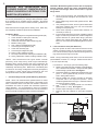
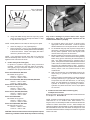
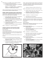
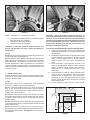
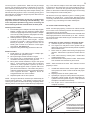
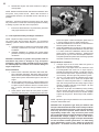
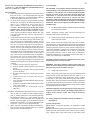
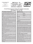
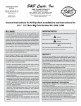
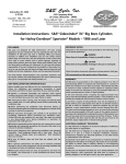
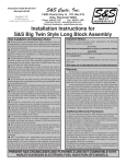
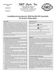
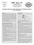
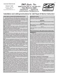
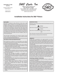
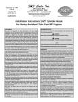
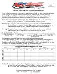
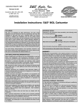
1
Instruction Sheet No. 2000
Revised 7-23-99
Copyright © 1980, 1985, 1988,
1991, 1992, 1999
by S&S Cycle, Inc.
All rights reserved. Printed in the U.S.A.
S&S Cycle, Inc.
®
14025 County Hwy. G
Box 215
Viola, Wisconsin 54664
Phone 608-627-1497
Fax 608-627-1488
Customer Service - [email protected]
Technical Assistance - [email protected]
Website: www.sscycle.com
3 7⁄16"/3 1⁄2" Bore Big Twin Stroker Kit Installation Instructions
OHV Engines 1936 and Later
Safe Installation and Operation Rules:
Before installing your new S&S stroker kit it is your responsibility
to read and follow the installation procedures in these instructions
and follow the basic rules below for your personal safety.
● Gasoline is extremely flammable and explosive under certain
conditions and toxic when breathed. Do not smoke. Perform
installation in a well ventilated area away from open flames or sparks.
● If compressed air is used during installation, be particularly
careful. Compressed air and particles dislodged using compressed
air are harmful to eyes and body. Wear protective goggles, and
always direct air stream away from body parts such as hands and
eyes and other people near you.
● When using solvents, degreasers and other chemicals during
cleaning and installation, read manufacturer's instruction label for
proper use. Exposure of some chemicals to skin, eyes and/or other
body parts may be harmful. Many items are flammable and present
a fire hazard. Use in well ventilated area and wear protective
clothing when using them to avoid personal injury.
● If motorcycle has been running, wait until engine and exhaust
pipes have cooled down to avoid getting burned before performing
any installation steps.
● Before performing any installation steps disconnect battery to
eliminate potential sparks while working on electrical components.
● Read instructions thoroughly and carefully so all procedures are
completely understood before performing any installation steps.
Contact S&S with any questions you may have if any steps are
unclear or any abnormalities occur during installation or operation
of motorcycle.
● Consult an appropriate authorized H-D service manual for correct
disassembly and reassembly procedures for any parts other than
those outlined in these instructions.
● Use good judgement when performing installation and operating
motorcycle. Good judgement begins with a clear head. Don't let
alcohol, drugs or fatigue impair your judgement. Start installation
when you are fresh.
● Be sure all federal, state and local laws are obeyed with the
installation.
● Be sure all fuel lines, supply and overflow, are routed correctly
and fuel line clamps are in place and tightened. Lines must not
contact exhaust pipes or other extremely hot surfaces where they
could melt or leak and catch fire.
● Before starting engine and riding motorcycle, be sure throttle
opens and closes smoothly. Turn handlebars to left and test throttle.
Then, turn bars to right and test throttle. To avoid possible loss of
control of motorcycle and potential personal injury to yourself or
others due to throttle sticking in open position, throttle must work
smoothly and return to a fully closed position when hand is removed
from throttle grip.
● Motorcycle exhaust fumes are toxic and poisonous and must
not be breathed. Run motorcycle in a well ventilated area where
fumes can dissipate.
IMPORTANT NOTICE:
Statements in this instruction sheet preceded by the following
words are of special significance:
WARNING
Means there is the possibility of injury to yourself or others.
CAUTION
Means there is the possibility of damage to the engine or
motorcycle.
NOTE
Other information of particular importance has been placed in
italic type.
♣♣
Denotes change in instructions since last revision.
S&S recommends you take special notice of these items.
WARRANTY:
All S&S parts are guaranteed to the original purchaser to be
free of manufacturing defects in materials and workmanship for a
period of six (6) months from the date of purchase. Merchandise
that fails to conform to these conditions will be repaired or replaced
at S&S’s option if the parts are returned to us by the purchaser
within the 6 month warranty period or within 10 days thereafter.
In the event warranty service is required, the original purchaser
must call or write S&S immediately with the problem. Some
problems can be rectified by a telephone call and need no further
course of action.
A part that is suspect of being defective must not be replaced
by a Dealer without prior authorization from S&S. If it is deemed
necessary for S&S to make an evaluation to determine whether
the part was defective, a return authorization number must be
obtained from S&S. The parts must be packaged properly so as to
not cause further damage and be returned prepaid to S&S with a
copy of the original invoice of purchase and a detailed letter outlining
the nature of the problem, how the part was used and the
circumstances at the time of failure. If after an evaluation has
been made by S&S and the part was found to be defective, repair,
replacement or refund will be granted.
ADDITIONAL WARRANTY PROVISIONS:
(1) S&S shall have no obligation in the event an S&S part is
modified by any other person or organization.
(2) S&S shall have no obligation if an S&S part becomes defective
in whole or in part as a result of improper installation, improper
maintenance, improper use, abnormal operation, or any other
misuse or mistreatment of the S&S part.
(3) S&S shall not be liable for any consequential or incidental
damages resulting from the failure of an S&S part, the breach of
any warranties,the failure to deliver, delay in delivery, delivery in
non-conforming condition, or for any other breach of contract or
duty between S&S and a customer.
(4) S&S parts are designed exclusively for use in Harley-Davidson
motorcycles. S&S shall have no warranty or liability obligation if an
S&S part is used in any other application.
2
PRESENT S&S CRANKCASES AND
FLYWHEELS ARE NOT COMPATIBLE WITH
HARLEY-DAVIDSON ELECTRONIC FUEL
INJECTION (EFI) MODELS.
CAUTION - Mismatched gasket surfaces due to improperly
aligned crankcase halves may cause unwarranted stress
on cylinder base flanges which could result in cylinder
flange failure.
A. Clean cases thoroughly and assemble both cases
without flywheels and tighten all case bolts as in final
assembly.
B. Place straight edge across base gasket surface. See
Picture 1.
C. If any misalignment exists, remove cylinder base studs
and place masking tape over cam and mainshaft
bearings to keep chips out.
D. Place cases squarely in mill and take minimum cut
necessary to clean up.
E. If stock cylinder studs are to be used, reinstall to original
height. If studs are provided in kit, install to height that
equals: thickness of cylinder base flange, plus base
gasket, plus cylinder base plate, plus washers, plus
base nut. Use Loctite Stud and Bearing Mount to secure
studs.
Installation of an S&S Big Twin Stroker Kit is comparatively easy
and can be performed by any average Harley-Davidson repair
shop equipped to do complete engine overhauls. No special
tools other than those used in normal overhaul operations are
required.
Read instructions thoroughly before starting work. When they
are completely understood proceed with installation.
Installation Steps:
1. Crankcase Alignment & Cylinder Mounting Studs (All)
2. Lower Oil Return Holes (Pan & Shovel)
3. Piston and Cylinder Fitting (All)
4. Crankcase and Piston Skirt Clearancing (All)
5. Breather Timing (All)*
6. Cam, Lifters and Tappet Blocks (All)
7. Connecting Rod Preparation (All)
8. Lower End Assembly (All)
9. Connecting Rod Alignment (All)*
10. Piston to Valve Clearancing (All)
11. Final Top End Assemble and Engine Installation (All)
12. Timing, Carburetion, Exhaust, Gearing & Break-in (All)
*NOTE - S&S recommends that engine builder consider
performing some steps during initial engine disassembly.
Breather timing check requires that most components be
assembled, and performing check upon disassembly may save
reassembly and cleaning time. While some or all related parts
concerned in connecting rod alignment check may be replaced,
it is helpful to check original parts combination and note
discrepancies which may alter installation of new parts.
1.
Crankcase Alignment & Cylinder Mounting Studs (All)
NOTE - Some H-D crankcase base gasket surfaces on which
cylinders are positioned do not align properly. This usually occurs
when crankcase halves used are from different crankcase
assemblies and were not paired and machined together at
Harley-Davidson. It is recommended to check for crankcase
misalignment even if crankcase halves are correctly matched to
prevent potential oil leaks and other mechanical problems.
2.
Lower Oil Return Holes (Pan & Shovel)
Big Twin cylinder oil return holes must be lowered in those
stroker conversions where oil ring crosses stock oil return
hole. This is necessary to prevent oil from returning above oil
ring which will cause engine to smoke.
NOTE - Oil rings will usually touch and/or cross oil return holes
with installation of stroke 4 1⁄2" or longer. Strokes shorter than 4
1
⁄2" do not require this step.
For strokes 4 1⁄2" and longer, perform following steps:
A. Directly in line with return hole in bottom of cylinder flange,
drill 1⁄4" diameter hole centered 1⁄2" away from base gasket
surface through cylinder sleeve. See Figure 1.
B. Place base gasket on cylinder base gasket surface, and
punch 1⁄4" hole in gasket directly in center of oil return
hole in base gasket surface.
C. Remove gasket from cylinder, and place on driveside
crankcase half in its respective position. Mark
crankcase gasket surface through 1⁄4" diameter hole that
has been punched in gasket.
D. Drill 1⁄4" diameter hole perpendicular into crankcase
gasket surface 5⁄8" deep. See Figure 2.
E. Perform steps A through D on other cylinder.
F. Bolt front and rear cylinders on drive side crankcase
half.
1/2"
Drill 1/4" diameter hole
Picture 1
Figure 1
3
Drill 1/4" diameter
hole, 5/8" deep
Driveside
crankcase
Figure 2
G. Using hole drilled through sleeve in step A as a guide,
drill a connecting hole to intercept hole drilled 5⁄8" deep
in step D on each cylinder.
NOTE - If base plates are to be used, be sure they are in place.
H. Clean dirt, filings, etc. out of passageways.
I. Press one piece of 3⁄4" long x 3⁄8" O.D. steel tubing provided
in kit into oil return hole in base gasket surface until tubing
is flush with surface. "Ream" hole slightly with drill to
remove any burrs that may exist.
NOTE - A very tight press fit with 100% seal is not critical as
tube will sufficiently divert oil flow to new hole. Loctite may be
applied to tube if fit seems too loose.
3.
Piston and Cylinder Fitting (All)
Fit pistons to cylinders using piston fitting instructions
provided. Check ring end gap and adjust as necessary.
After gapping rings, keep them separate so they can be
installed in their proper locations later.
Piston Series #92-2700, #92-2730
with slotted oil ring groove
Close fit – .0015" to .002"
Loose fit – .0025" to .0035"
Piston Series #92-2500, #92-2510, #92-2600, #92-2610
Close fit – .002" to .0025"
Loose fit – .003" to .0035"
Piston Series #92-2720, #92-2730
with holed oil ring groove
Close fit – .002" to .003"
Loose fit – .0035" to .004"
Piston Series, #92-2400, #92-2420,
Close fit – .0008" to .0013"
Loose fit – .002" to .0025"
Piston Series #92-2800
with slotted oil ring groove
Close fit – .0025" to .003"
Loose fit – .0045" to .0055"
Piston Series,#92-2800, #92-2900
with holed oil ring groove
Close fit – .0035" to .004"
Loose fit – .005" to .006"
CAUTION - Failure to follow instructions and perform required
clearancing, installation and/or break-in procedures correctly
Picture 2
may result in damage to pistons and/or other engine
components. S&S voids its guarantee if pistons are not
installed and/or broken in properly.
A. For maximum piston and ring life, fit pistons using
appropriate close fit dimensions. Close fit requires
absolute adherence to new engine break-in as outlined.
B. For immediate drag strip use, fit pistons using loose fit
dimensions. Attempt to break in rings and pistons with
50 easy miles if possible. Piston and ring life will be
reduced when using loose fit dimensions.
C. Measure all pistons across thrust faces 90° to wristpin
holes. Make a series of measurements starting directly
below oil ring groove and ending at extreme bottom of
skirt. Use widest measurement to represent size of
piston. Some pistons measure widest at extreme bottom
of skirt. Others measure widest somewhere between oil
ring groove and extreme bottom of skirt. If piston is
notched for placement in rear cylinder, use measurement
directly above notch as extreme bottom of skirt
measurement.
D. S&S recommends the use of #220-#280 grit stone for
final honing of cylinders for all stock-bore stroker
engines.
E. Follow procedure recommended in H-D service manual
for boring and honing V2 type cylinders. S&S Cylinder
Torque Plate Kit, S&S Part #53-0016, or H-D torque
plates, H-D Part #33446, are required when fitting V2
cylinders to simulate engine operating conditions.
Cylinders may distort more than .001" if torque plates
are not used.
4. Crankcase and Piston Skirt Clearancing (All)
Crankpin Nut Clearance
Bosses on inside of cam side crankcase half must be clearanced
for crankpin nut. See Picture 2.
NOTE - Crankpin nut will usually clear on 80 Shovel head and V2
cases when 4 1⁄4" or 4 3⁄8" stroke is used. When stroke 4 1⁄2" or
longer is used, nut will usually hit. S&S recommends all cases be
checked no matter what stroke is used. S&S Crankpin Nut
Clearancing Gauge, Part #53-0005, for cases 1958 and later, and
Part #53-0009 for cases 1957 and earlier are designed to mark
crankcase that allows sufficient crankpin nut clearance for specific
stroke to be used.
4
If S&S gauge is not available, perform following procedure:
A. Paint bosses with machinist's blue.
B. Use divider to scribe arc on blued bosses. See Figure
3. Formula for spread of divider is:
Distance = ( 1⁄ 2 Flywheel Stroke) + ( 1⁄ 2 Diameter of
Crankpin Nut Measured Across Points) + ( 1 ⁄ 16 "
Clearance) - (1⁄2 Outside Diameter of Race)
NOTE - If pistons have piston to piston clearance notches ground
on thrust face edges, place notches toward center of engine.
Consult piston installation instructions included with pistons for
proper piston direction placement.
C. Install both cylinders and secure each with one nut.
NOTE - If base plates are to be used, be sure they are in place.
NOTE - On Panhead engines, above procedure is recommended
to insure removal of minimum material necessary.
Caution - Early Pan cases are not as strong and are
machined with oil supply passageways to heads closer to
surface of boss. Removal of excessive material may weaken
thinner cases and/or break into oil passage.
C. Place masking tape over both ends of camshaft and
mainshaft bearings to keep out chips.
D. Grind shaded areas to adjacent machined depth.
E. Mock up right side flywheel in crankcase half with
mainshaft and crankpin installed with bearings, thrust
washers, etc. in place.
F. Rotate flywheel and note any contact.
G. If flywheel does not rotate freely, check contact areas
and grind more clearance.
H. Repeat procedure until sufficient clearance is obtained.
NOTE - A minimum of 1⁄16" clearance is required.
CAUTION - Insufficient clearance between crankpin
nut and crankcase will cause contact and may dam
age components.
Connecting Rod Clearance
Front and rear of flywheel cavity inside crankcases andcylinder
spigots must be clearanced for connecting rods. Picture 3 shows
rear side of flywheel cavity.
NOTE - Clearance must be checked and filed if needed on front
side also.
Procedure to check these points is performed as follows:
A. Mock up right side flywheel in crankcase half with
mainshaft and crankpin installed with bearings, thrust
washers, etc. in place.
B. Assemble pistons without rings on their proper
connecting rods, and place connecting rods on crankpin.
Installation of wristpin clips is not necessary.
D. Rotate flywheel until rods contact areas to be
clearanced. Note angle that must be filed.
E. Disassemble cylinder and connecting rods and file
crankcase and cylinder spigot for clearance.
NOTE - A minimum of 1⁄16" clearance is required.
F. Reassemble and check clearance.
G. This procedure must be done for both crankcase halves.
CAUTION - Insufficient clearance between connecting rods
and crankcases will cause contact and damage to
components.
Piston Clearance
Pistons must be clearanced to avoid contact with each other
and with flywheels. See Pictures 4 and 5.
Piston to Piston Clearance
A. Perform steps A through C in "Connecting Rod
Clearance" above.
B. Rotate flywheel to position where pistons are closest to
each other. See Picture 4.
C. Check clearance between pistons.
NOTE - A minimum of 1⁄16" clearance is required.
D. Disassemble cylinders and pistons, and carefully file
edge of piston skirts until clearance is obtained.
E. Reassemble and check clearance.
Piston to Flywheel Clearance
A. Perform steps A through C in "Connecting Rod
Clearance" above.
B. Rotate flywheel to position where front piston is closest
to flywheel. See Picture 5.
C. Check clearance between piston and flywheel.
Distance = 1/2 Stroke + 1/2 Dia. Crankpin
Nut Across Points - 1/2 Outside
Dia. Main Race + 1/16" Clearance
Figure 3
Picture 3
5
Picture 4
D. Disassemble cylinder and piston, and carefully file piston
skirt until clearance is obtained.
E. Reassemble and check clearance.
F. Repeat procedure for rear piston.
CAUTION - Insufficient clearance between pistons and
pistons and flywheels will cause contact and damage to
components.
NOTES
● Material removed from pistons for clearancing purposes will
not adversely affect flywheel balance.
● Some S&S kits utilize flywheels with diameters smaller than
stock (stock Big Twin flywheels are 8 1⁄2"). This is done to maximize
piston skirt length. Our experience has shown that when small
diameter flywheels are used it is desirable but not absolutely
necessary to build up flywheel scraper. If flywheel scraper is not
built up, oil thrown off flywheels may cause excessive oil burning
in the rear cylinder.
5. Breather Timing (All)
To maximize efficiency when scavenging oil from flywheel cavity
in Big Twin engines, it is necessary to check and usually modify
crankcase breather timing.
To check and modify breather timing perform following steps:
A. Bolt degree wheel pointer to drive side crankcase half
using center case stud and nut. Position pointer towards
sprocket shaft.
B. Install degree wheel assembly on sprocket shaft. Rotate
flywheel assembly so front piston is at TDC, top dead
center. Position degree wheel on sprocket shaft so
pointer indicates 0° TC, top center, and tighten set
screw.
C. Rotate flywheels in normal direction of travel to 10°
before TC as in Picture 6. Observe breather gear and
hole in crankcase through tappet block opening to
determine hole in breather gear and hole in case
relationship.
D. Rotate flywheels to 7° after TC. Again note relationship.
If edge of hole in gear appears in hole in crankcases
during this span of degrees, then cases have proper
opening specs. If not, then opening side of hole in cases
must be ground. Grind hole to 7° before TC, maximum
timing specifications.
E. Rotate flywheels to 55° after BC, bottom center.
ATI
OT O
Opening Side
N
NOTES
● Breather timing can be checked after other crankcase
clearancing is done or during initial disassembly.
● Early crankcase breather opening is a rough cast elliptical
hole. In mid 1970s some care was taken to improve breather
timing at H-D. Consequently, later vintage crankcases have a
breather opening that is square.
● Objective of this step is to modify cases so that hole in cases
is located in same position as hole in breather gear with opening
and closing sides of hole in case in correct location for proper
breather timing.
● S&S Part# 53-0020, Degree Wheel Kit, was designed to aid
in checking breather timing. Procedures below assume an S&S
degree wheel is used.
● S&S recommends grinding hole to maximum timing
specifications. If there is any doubt and timing falls within specs,
leave breather opening alone. See Figure 4 for breather timing
specifications.
CAUTION - Improper breather timing causes poor oil
scavenging from flywheel cavity and incorrect crankcase air
pressure. These conditions may cause unwarranted engine
oil leaks around gaskets and seals and probable oil burning
due to oil blow by past piston rings. Removal of excessive
material from breather gear opening is irreversible and
damage to crankcases may result.
R
NOTE - A minimum of 1⁄16" clearance is required.
Picture 5
Closing Side
.690
1.165
Figure 4
6
Picture 6
Observe breather gear and hole in crankcase to note
their relationship.
F. Rotate flywheels to 92° after BC and note relationship.
See Picture 7. If back edge of hole in gear disappears
from view during this span of degrees then cases have
proper closing specs. If not, then closing side of hole
in cases must be ground. Grind hole to 92° after BC,
maximum timing specifications.
G. Note location of hole in gear as opposed to hole in
crankcases. See Figure 4. Grind hole in cases so
location matches holes in gear with respect to where
toothed portion of gear hits cases. Picture 8 shows
finished breather gear opening.
H. Optional Step
NOTE - To further maximize breather efficiency some engine
builders modify or remove screen in breather gear.
CAUTION - Breather gear screen stops foreign material from
getting into gear side cavity where material could possibly
stop oil pump and/or damage other parts. No oil to engine
will result in damage to engine components.
To modify screen:
a. Early gears - Remove clip that holds screen in
place.
b. Early gears - Turn screen so it covers hole made
by removing clip.
c. Early gears - Spot weld screen in place.
d. All gears - Drill all holes in screen as large as
possible without weakening screen.
Picture 7
lift cam installation an easy job. If you are using a high lift
camshaft perform any required head work and valve spring
spacing per manufacturer's instructions.
● Knucklehead strokers built using 1936 to '47 cases may use
any aftermarket Knuckle cam such as an Andrews "S" or "K"
grind. Knuckle heads installed on later crankcases, 1948 and
up, should use cams such as "575" Sifton. In Pan or Shovel
575's lift is much higher, but when used with Knuckle heads, lift
is only .400" since Knuckle rocker arm ratio is 1 to 1.
● Evolution V2 strokers have been tested using both solid lifters
and hydraulics. We recommend using stock hydraulic assemblies
in all V2 applications. They are far superior to early style Pan/
Shovel assemblies and hold up extremely well under most
conditions. To maximize efficiency and reduce potential valve
float in high rpm situations, S&S HL2T Hydraulic Lifter Limited
Travel Kit should be used in all V2 performance applications. Part
#33-5338 for 1985 and #33-5339 for 1986 and later.
● Panhead, 1953 and later, and Shovelhead strokers with solid
lifters should have tappet block hydraulic lifter oil feel holes
plugged to prevent excess oil escaping above lifters from filling
pushrod tubes causing potential oil leaks.
To do this, perform following steps:
A. Starting at gasket surface end of oil feed passageway
in tappet block base, thread 8-32 tap into oil passage
hole. Turn tap until tap end just starts to enter cam
follower hole.
B. Screw 8-32 x 3⁄16" allenhead set screw in passageway
until it stops.
NOTE - This procedure increases area that air and oil have to
pass from breather gear cavity to gear side.
6.
Cam, Lifters and Tappet Blocks (All)
NOTES
● Big inch, stroked H-D engines with compression ratios of 8
1
⁄2+ to 1 or more respond well to higher lift, longer duration cams.
Engines with lower compression ratios should have shorter
duration cams. S&S offers cams for all Big Twins except
Knuckles that we have run in our test engines. We recommend
their use along with S&S high performance valve springs and
retainers. These components along with other valve train parts
are available in kits that not only satisfy most any degree of
rebuilding required but also make valve spring spacing and high
Picture 8
7
C. Perform steps A and B to other tappet block.
NOTE - If hydraulic lifters are ever reinstalled, plugs must be
removed.
CAUTION - Restricted oil flow to hydraulic lifter assemblies
causes lifters to operate with improper oil pressure which
may damage them or other valve train components.
7.
Connecting Rod Preparation (All)
NOTE - If S&S connecting rods are used, follow instructions
that accompany rods since rod preparation below has already
been done.
If S&S rods are not used, perform following steps:
A. To insure adequate oil on sides of rods and matching
thrust surfaces of flywheels, S&S recommends that four
grooves be ground on each side of both front and rear
connecting rods. See Figure 5. Make these grooves
.020" to .030" deep and .030" to .040" wide and should
be ground 90° from each other. After making grooves,
remove all sharp edges and burrs with emery cloth.
B. With rods assembled, measure distance between rods at
closest points in wristpin holes. If measurement exceeds
2.950" as shown in Figure 5, grind female rod at points
where male rod makes contact to achieve sufficient
clearance.
NOTE - Rods clearanced to this dimension provide adequate
clearance for strokes up to and including 5". Do not remove any
more material than is necessary to obtain required clearance.
CAUTION - Inadequate clearance between rods or too much
clearancing on rods will cause unwarranted stress on
connecting rods, rod bearings, pistons, etc. resulting in
possible failure of one or all aforementioned parts.
C. Thoroughly clean all parts to remove dirt, filings, etc.
CAUTION - Burrs, dirt, filings, etc. left on connecting rod
components may circulate in oil damaging other parts
possibly causing engine failure.
8.
Lower End Assembly (All)
2.950
Grind stroke
clearance in
this area
NOTES
● S&S Big Twin flywheels with serial numbers that start with a
letter or those numbered 1382 or higher are made from closed
die, heat treated, steel forgings. They do not have connecting
rod thrust washers like earlier S&S flywheels, because present
flywheel material is harder than thrust washers previously used.
● S&S flywheels come with either one or three timing marks.
A single timing mark represents front cylinder. On flywheels with
three timing marks, an "F" stamped by a mark means front cylinder,
an "R" means rear cylinder and a "TF" means top dead center front
cylinder. In both cases, when front or rear mark is placed in center
of timing hole it means that that cylinder is timed at 35° before top
dead center. We recommend that big inch H-D Big Twin engines
be timed at 35° initially. See Step 12, "Ignition Timing".
● Usually S&S flywheels are balanced before leaving our facility.
Some customers prefer to do their own balancing or to have
another balancing shop do the work for them. This is acceptable
in most cases. However, we have had some bad experiences
with dynamically balanced flywheels that have forced us to void
our guarantee if flywheels have been balanced in this fashion.
CAUTION - Flywheels assembled improperly prior to being
dynamically balanced may sustain irreversible damage to
mainshaft and crankpin tapers during actual balancing. S&S
voids its guarantee if flywheels have been balanced in this
fashion.
● Assembling flywheels, mainshafts and connecting rods can
be easy or difficult. Degree of difficulty is determined by builder
technique and parts at his disposal. While S&S flywheels have
been noted for their easy truing qualities, they can be difficult to
true if a defective part is used that should have been detected
before assembly.
● Cleaning parts prior to and during assembly and keeping parts
clean after final assembly are imperative to minimize
contaminants that may circulate in oil and shorten engine life.
Use cleaning agents that do not leave harmful residues, and be
sure to read and follow manufacturer's instruction label before
use. Use drills and compressed air to clean all oil passageways
of dirt, filings, etc. whenever possible.
WARNINGS
● Some solvents, degreasers, gasoline and other
chemicals are harmful to skin, eyes and other body parts.
Many items are flammable and present a fire hazard. Read
manufacturer's instruction label for proper use. Use in well
ventilated area and wear protective clothing when using
them to avoid personal injury.
● Compressed air and particles dislodged using
compressed air are harmful to eyes and body. Wear
protective goggles when using compressed air and always
direct air stream away from body parts such as hands and
eyes and other people near you.
Perform following steps when assembling flywheels:
A. Thoroughly clean all parts to be used. This includes
mainshafts, main bearings, connecting rods, rod
bearings, crankpin nut retainers and screws if they are
to be used, keys and flywheels including tapers and
keyways.
Grind four oil
grooves on both
sides of forked rod
Figure 5
CAUTION - Burrs, dirt, filings, etc. left on flywheel assembly
parts may circulate in oil damaging other parts possibly
causing engine failure.
8
B. Check both mainshafts between centers for taper
surface to bearing surface concentricity. Make sure
centers on shafts are clean beforehand. If tapers and
bearing surfaces are concentric with each other and
with center, then truing will be easier. See Picture 9.
NOTE - S&S recommended rod side play is .015" to .035". Rod
Side Play = (Distance from Pad to Pad) - (Female Rod Width)
CAUTION - Incorrect connecting rod side play may cause
excessive rod side thrusting and potential damage to rods,
flywheels and other engine components.
NOTE - Current H-D specs. allow maximum of .001" runout
between taper and bearing surfaces. We feel this is too much
and prefer to see .0003" or less with an absolute maximum of
.0005". S&S shafts are .0003" or less.
C. Inspect keyways and oil holes for burrs in flywheels and
remove if necessary.
D. With key in shaft, insert into respective tapered hole in
flywheel and check to see that key does not bottom in
groove. If key bottoms out, file flat side of key, not
rounded side, until shaft with key in place fits in flywheel
without bottoming out. Check crankpin and crankpin
key also.
E. Reclean mainshaft tapers, crankpin and flywheel tapers
with lacquer thinner.
F. Assemble mainshafts in respective flywheels. Coat
taper and threads of each shaft with green Loctite during
assembly. Install crankpin in camside flywheel using
Loctite also. Tighten all nuts to at least factory torque
specs minimum. When S&S shafts are used, follow
instructions included with them.
NOTE - S&S recommends to tighten nuts very tight. We use a
3
⁄4" drive breaker bar and a five foot piece of pipe when assembling
flywheels.
After right side flywheel, pinion shaft and crankpin are
assembled, blow air through pinion shaft oil feed hole
to check for blockage.
CAUTION - Partially or completely blocked oil feed
passageways may cause irreversible damage to bearings
and other engine components.
G. Measure width of female rod on crankpin end. See
Picture 10. Measurement should be 1.743" to 1.745".
H. Assemble left and right flywheels and moderately snug
nuts. Do not worry about them being true. Measure
distance between connecting rod thrust pads. See
Picture 11.
Picture 9
If difference is less than .020", female rod must be
ground on sides as final tightening will pull wheels closer
together. Rod side play diminishes about .015" when
crankpin nut is final tightened. Take equal amounts off
each side if amount to be removed is more than .010".
If there is no rod side play try different crankpin. If rod
side play is more than .035", try different crankpin. We
have run side play of as much as .045" without serious
consequences. If crankpin is changed check rod
bearing clearance. If side play is excessive and different
crankpins do not correct problem, contact us.
NOTE - If material is removed from sides of female rod, overall
width of bearing cages must be reduced so bearings and cages
are free to float with rods without contacting flywheel thrust pads.
Bearing cage side clearance of .008 to .020 less than rod width
is recommended.
CAUTION - Connecting rod bearing and cage assemblies that
are wider than female rod may become damaged upon contact
with flywheel thrust pads. Damaged rod bearing assemblies
and/or foreign material from damaged components circulating
in oil could cause further destruction and possible failure of
other engine parts.
I.
Finish assembling flywheels and rods. Flywheel
assemblies 1972 to early 1981 may be more difficult to
true because of the 8 1⁄2° sprocket shaft taper. Following
above procedures will help diagnose problem if difficulty
should arise.
9. Connecting Rod Alignment (All)
After flywheel assembly is installed in crankcases, rods must
be checked for straightness. S&S Rod Checking Pin, Part#
53-0002, was designed to help perform this procedure. It may
also be necessary, to fabricate a rod bending tool as illustrated
in Figure 6.
NOTE - The purpose of this procedure is to correct for machining
tolerance discrepancies in components which may lead to pistons
Picture 10
9
not running true in cylinder bores. While rods may be straight
and true, it is sometimes necessary, to bend them to correct for
these machining discrepancies. Do not bend rod by using tool
in wristpin hole as this method may distort wristpin bushing. We
also feel that using a piston in lieu of a checking pin may prove
inaccurate due to variations in lengths of piston skirts from one
side of piston to the other.
CAUTION - Pistons which do not run true in cylinder bores
may cause excessive connecting rod side thrusting. This
in turn may lead to premature ring, piston, connecting rod
and rod bearing wear and eventual failure of these parts.
Checking Pin Procedure
A. Insert checking pin into wristpin hole. Place strips of paper
between checking pin and crankcase cylinder gasket
surface and apply slight downward pressure to wristpin
end of rod by rotating flywheels. Pull papers out slowly.
Drag on papers should be equal.
B. Rotate flywheels in opposite direction until checking pin
contacts cylinder gasket surface again. Repeat
procedure to rod again. If drag on papers is equal no
bending is required. If one paper is loose, use rod
bending tool to tweak rod in direction of loose paper
and recheck. See Picture 12.
C. Repeat checking and bending procedure for other rod.
Visual Procedure
A. Install pistons on rods without rings or wristpin clips.
Bolt cylinders with gaskets in place.
B. Move piston tight towards camside of engine.
C. Turn engine over in normal direction of travel 2 or 3
revolutions and observe piston during process.
D. Move piston towards driveside of engine and repeat
Step C. If inaccuracies are present due to machining
variations in cases, cylinders or pistons, top land of
piston deck will appear closer to cylinder wall at one
point around circumference. This means that piston is
cocked in cylinder bore and can be corrected by bending
rod in opposite direction. Figure 7 shows an
exaggerated side view of this condition.
E. Repeat Steps B to D for other cylinder.
NOTE - All engines should be checked upon disassembly for
incorrect piston alignment. This applies to those which are
receiving new pistons as well as those being completely rebuilt.
Observe pistons for wear spots on sides above top compression
ring. If one side near wristpin is worn clean while side opposite
is carboned up, then piston was not running straight and true in
cylinder bore. Piston will also generally show diagonal wear
pattern on thrust faces of skirts and possibly signs of connecting
rod to wristpin boss contact inside piston.
We feel that not enough emphasis is given to checking piston
alignment in cylinder bore. Proper piston alignment means
connecting rods will thrust to sides less minimizing added stress
on pistons, rings, rod bearings and other related parts.
10. Piston to Valve Clearancing (All)
NOTE - All valve spring spacing, rocker arm to collar and rocker
arm to rocker cover clearancing must be done before piston to
valve clearancing can be checked.
S&S pistons have sufficient valve clearance when used with most
street high performance cams with lifts up to .525". However,
we recommend that valve clearancing be checked if other than
stock cam is used.
Check piston to valve clearance in following manner:
A. Assemble engine with exception of cylinder heads.
B. Turn engine over until piston in front cylinder is at top
dead center. Paint area around valve pockets on pistons
with machinist's blue.
C. Place valves in cylinder head leaving off springs and
retainers. Place head on cylinder and secure with one
bolt.
D. Lower valves until they contact piston. Rotate valve
marking painted area.
E. Remove head and check points of contact. Valve should
fit in recessed area machined in piston dome.
NOTE - S&S recommends at least .060" clearance around
periphery of valve.
F.
If insufficient clearance exists, remove piston and grind
valve pocket until head of valve fits flush with proper
clearance.
G. Repeat procedure for other cylinder head.
H. Spread layer of putty into valve pockets in both pistons.
I. Assemble cylinder heads and bolt assemblies on
cylinders with head gaskets in place. Install pushrods
and adjust to simulate final assembly.
J. Turn engine over in normal direction of travel two
complete revolutions.
.510"-.520" Wide Slot
11/8"
4"
22"
11/4"
Picture 11
Rod bending tool shown here
can be fabricated and welded.
This tool is designed to grasp
rod immediately below wristpin
end on I-beam section.
Figure 6
10
K. Disassemble engine and check thickness of putty in
valve pockets.
NOTE - S&S recommends at least .060" clearance between valve
and piston valve pocket recess. While .060 clearance is
recommended minimum, it is advisable to have .080 and up, if
possible.
CAUTION - Insufficient clearance between piston and valves
may cause them to contact each other during operation resulting
in damage to piston and valve train components.
L.
If less than .060 clearance in any area exists, grind area
until proper clearance is achieved.
Picture 12
11. Final Top End Assembly and Engine Installation
NOTE - All previous steps must be completed.
On engines other than Evolution Big Twins, we recommend
installing cylinders without heads bolted to cylinders for two
reasons:
1. Combined weight of cylinder and cylinder head makes
assembly cumbersome and hard to handle during
installation.
2. Separate installation of cylinders and cylinder heads
permits more leeway for adjustment to achieve a better
manifold fit.
CAUTION - Installation of cylinders and cylinder heads as
assemblies may result in damage to rings and piston
assemblies. Improper intake manifold fit may cause intake
air leaks/improper fuel mixture and resultant damage to
engine components.
Piston Installation
1. Pistons Series #92-2400, #92-2420, #92-2500, #922510, #92-2600, #92-2610, #92-2700, #92-2720 and
#92-2730 have offset wristpins and must be installed with
dimple cast in piston dome toward right or cam side of
engine.
2. All other pistons series have no special features and
can be installed any way the builder desires unless there
is a piston to piston clearance bevel on one skirt thrust
face. If there is, this bevel must go towards center of
engine.
3. Some pistons series have all of the piston to piston
clearance in the rear piston. Install rear piston with notch
4.
6.
toward front piston. Make sure dimple in piston dome is
in correct position if piston is offset wristpin type.
Check all installations for a minimum of .060" clearance
between pistons at bottom of stroke.
Check all installations for a minimum of .060" clearance
between pistons and flywheels at bottom of stroke. New
4 5⁄8" stroke stock bore installations should come with
proper piston to flywheel clearance. Replacement
pistons may or may not come with adequate clearance.
Compare replacement pistons with ones being replaced
and make corrections accordingly.
Wristpin Retainer Installation
1. If wristpin clips are to be used, make sure groove is
free of burrs and foreign material.
2. Round "wire" style clips which are identical to and
interchangeable with stock H-D V 2 clips require a
specially chamfered end wristpin. Install clips using HD recommended procedure. Special indexing of clip is
not necessary. Be sure clip is fully seated in groove.
3. "Tru-Arc" style clips should be installed using proper
tool. Clips should not be used with wristpins with
chamfer on end that is greater than 1⁄64". Install clip with
open side facing downward and sharp edge of clip to
outside of wristpin hole away from wristpin. Be sure
clip is fully seated in groove.
4. "Spiral-Loc" style clips are installed by slowly working
clip into wristpin hole using thumb nail in a screwing
motion. Once entire clip is in hole, use another wristpin
to push clip into groove. Be sure clip is fully seated in
groove.
NOTE - Spiral-loc type wrist pin retainers must not be used with
wrist pins with beveled ends.
Figure 7
CAUTION -Use of Spiral-loc type wrist pin retainers with
wrist pins with beveled ends could result in wrist pin retainer
failure and major damage to engine. Teflon wrist pin buttons
must only be used in pistons where buttons are fully
supported by wristpin hole. They are used in place of and
not in conjunction with conventional wristpin retaining clips.
Recommended wristpin endplay is .010" to .060" and is
determined by subtracting length of wristpin with a button
on each end from finished cylinder bore. To make fitting
easier S&S buttons come in two widths for stock bore
applications. "A" buttons are thinner and "B" buttons are
11
thicker. Use two A buttons, Part #94-9251, for bore sizes 3
7
⁄16" std. to 3 7⁄16" +.040, two B buttons, Part #94-9252, for bore
sizes 3 7⁄16" +.050 to 3 7⁄16" + .090.
Ring Installation
1. Piston ring widths have changed on some piston series
from time to time. It is recommended that ring parts
supplied with pistons be recorded for future reference
in the event replacement rings are required.
2. Oil rings are three piece circumferential expander
cylinder type. End gap on all rails except those for V2s
with 3 1⁄2" (3 7⁄16" +.060) bore is .010" to .040". On V2s
with 3 1⁄2" bore it is .015" to .065". Grind end gaps as
necessary. Do not leave burrs as they will scratch
cylinder walls. Do not shorten expander for any
reason. Place end gaps as follows: Expander – gap in
center of thrust face 90o to wristpin. Bottom rail – gap
2" to right of expander gap. Top rail – gap 2" to left of
expander gap.
3. Compression rings may be cast iron type, chrome faced
cast iron type, moly faced cast type and chrome type.
The most common combinations supplied are two
chrome faced cast, one chrome faced cast and one cast
iron, and one moly faced cast and one cast iron.
Chrome faced or moly faced ring always goes in top
groove. Cast iron type usually goes in second groove.
Cast iron type is usually a reverse torsion style ring
distinguished by an inside diameter bevel on one side
of ring with a "dot" or oversize mark on other side of
ring. If two cast iron compression rings are supplied in
set, check to see if one is reverse torsion style ring.
Reverse torsion style ring always goes in second
groove. The following rules apply to compression ring
identification and placement. Rules are listed in order
of priority.
a. Chrome or moly ring goes in top groove.
b. Cast iron regular or reverse torsion goes in second
groove.
c. Any identifying "pip" marks, dots or oversize marks
go to top of piston.
d. One dot goes in top groove, two dots go in second
groove.
e. If both have one dot or two dots, they can go in
either groove.
f. If ring has dots and inside diameter bevel, dots go
to top of piston.
g. If ring has no dots and inside diameter bevel, bevel
goes to top of piston.
h. If ring has not dots, etc. and no bevel, it can go
either way.
End gap on all compression rings except V2s with 3 1⁄2" bore is
.012" to .030". On V2s with 3 1⁄2" bore end gap is .008" to
.030". In certain instances, the next oversize ringset may
be supplied with pistons, ie. + .060" oversize rings with
+.050" pistons. This is permissible but end gaps must
be filed. Place end gaps on all compression rings as
follows: Second groove – 3" to right of oil expander gap.
Top groove – gap 3" to left of oil expander gap.
4. When rings are compressed for piston installation in
bore, be sure oil ring expander ends do not overlap
and ring stays assembled properly.
Final Assembly
♣♣ CAUTION - To avoid parts damage and obtain accurate
torque readings, clean head bolt threads thoroughly before
installation. For Knuckle, Pan, or Shovelheads, head bolt
threads and area of bolt head that contacts washer (if
applicable) or cylinder must then be lubricated with
Permatex Anti-Seize Lubricant or similar anti-seize
compound. S&S has received reports of thread damage in
these engines associated with use of engine oil to lubricate
head bolts. Use of clean engine oil is preferable for V2-style
headbolts only.
A. Install and tighten cylinders, cylinder heads and manifold
as in standard assembly.
NOTE - Retighten cylinder base nuts and head bolts as
necessary after engine has been run.
B. Install engine in frame and check for engine to frame
and/or gas tank contact.
NOTE - Engine with longer cylinders than stock due to cylinder
base plates may contact rigid mount frame and/or right gas tank
with rear rocker box. S&S recommends there be .060" minimum
clearance between engine and other chassis components on
rigid frame installations. Rubber mount chassis have adequate
room for any engine combination. Up to .060" or .070" may be
ground from rocker box cover in some areas for clearance.
Additional material may be sparingly removed from frame if
rocker cover clearancing is inadequate.
CAUTION - Excessive material removed from rocker cover
may damage cover causing oil leaks.
WARNING - Excessive material removed from frame may
cause structural damage and possible failure resulting in
personal injury to you or others near you.
C. Install engine head mount.
NOTE - Stock head mount will be short if you are installing S&S
stroker kit with cylinder base plates thicker than .0625" (1⁄16"). If
1
⁄16" thick or less plates are used, modify stock mount. If plates
thicker than 1⁄16" are used, install S&S heavy duty head mount,
part #93-4054. This mount is heavy duty and designed especially
to provide support for tall, big inch engines. Its two piece design
permits precise head to frame alignment which reduces stress
and potential head mount failure.
CAUTION - Improper mounting of engine in frame may cause
engine to come loose resulting in damage and/or failure of
engine motor mounts and/or other engine mounting
brackets.
12. Timing, Carburetion, Exhaust, Gearing and Break-in
(All Engines)
Ignition Timing Notes
● See Step 8, "Lower End Assembly", for explanation of S&S
timing marks.
● S&S flywheels have timing marks that position pistons at 35°
before top center, same as stock, when mark is in center of timing
hole. Placing mark to right side of hole or just entering hole
12
advances timing almost 5°. Vice versa, if mark is just leaving
hole, timing is retarded almost 5°.
● Maximum performance in early engines traditionally has been
with timing set at 37° to 39°, but because of poor gasoline,
detonation, etc. it is advisable to stay with 35°. Some builders
will even retard ignition timing slightly because of aforementioned
problems, but if you do, watch heat build-up. If there is any
doubt, stay with H-D factory recommended settings.
● Evolution V2 SIDEWINDER tests conducted on our dyno have
indicated that the best horsepower will be produced with timing
set from 30° to 35°, depending on cylinder head design,
compression ratio and type of fuel. Evolution 98" engine used
was equipped with point type ignition system which allowed us
maximum flexibility to advance or retard ignition timing . It also
removed RPM limitations set by stock “black box”. If stock
electronic system is retained, contact your local H-D dealer for
part number of ignition module that is recommended for high
performance, high rpm usage.
● Whatever ignition system is used, the best rule of thumb for
most situations is to follow stock timing specs and watch for
signs of detonation and/or excessive heat.
● Ignition timing for engines with dual plugged heads should
generally be retarded 5-8° from the stock setting. However, due
to the large number of variables involved, optimum ignition timing
is impossible to accurately predict and must be determined for
each engine by experimentation
CAUTION - Improper ignition timing may cause excessive
engine heat which may damage pistons and/or other engine
components.
Carburetion Notes
● All S&S test engines have been run with S&S carburetors. A
Super E or Super G carburetor is recommended for most
strokers. Consult carburetor jetting instructions for specific jetting
recommendations.
● If another type carburetor is used, it must be made to run
rich enough so engine is not damaged. Other carburetor types
are a personal problem and we cannot answer questions
concerning them. It is best to call carb manufacturer if you have
any questions.
Exhaust Systems Notes
● To establish performance guidelines, S&S used 30” long stock
diameter drag pipes on pre-Evolution engines with good results.
We suggest you try them on these engines to establish a baseline
to compare with other systems. Evolution engines are easier to
carburate with muffled systems.
● You might ask the manufacturer of the exhaust system you
are considering if he has had any experience with S&S strokers.
Many systems are made for looks with little consideration given
to performance. Most stock systems and many aftermarket ones
tried are too restrictive for good performance. Harley-Davidson
does offer a series of mufflers that can be used with stock header
pipes. These work very well in most situations and offer an
inexpensive alternative to a new exhaust system. We prefer
their tapered and baloney cut styles. Evolution engines should
use a system equipped with a crossover pipe that connects front
and rear header pipes.
Gearing Note
● Gearing depends on total weight of machine and rider/s, size
of engine, caming, exhaust system and type of riding to be done.
Most strokers are capable of pulling more gear. We suggest
you break engine in with stock gearing to minimize lugging
engine. After engine is broken in you will have a better feel of
its potential and can change gearing accordingly.
● For those who wish to determine their final drive gear ratio
the formula is as follows:
Engine Revolutions Per One Revolution of Rear Wheel=
(Clutch Sprocket*) x (Rear Wheel Sprocket*)
(Motor Sprocket*) x (Trasmission Sprocket*)
*Number of teeth on each sprocket
Break-In Procedure
This procedure applies to all engines with close fit pistons.
NOTE - These engines must be broken in. They will feel
extremely strong so resist the impulse to turn it on. Break it
in properly.
CAUTION - Lugging engine at low rpms and/or running
engine prematurely at high rpms may result in damage to
pistons and/or other engine components. S&S voids its
guarantee if engine is not broken in properly.
1.
On initial engine startup, don’t just sit and idle motor
while you admire your work, or tinker with minor
adjustments. Heat buildup can be excessive. Do not
let engine overheat.
IMPORTANT NOTE - V2s ONLY - Proper first time engine startup and break-in for first 15 minutes is critical to achieve
permanent and lasting head gasket seal. Upon initial start-up,
idle engine at 1000-1500 rpm until cylinder head temperature
reaches about 250°. Do not crack throttle or put any load on
engine during this time. Heat buildup is necessary to cause
heads and cylinders to expand and seal. Do not let heat get
excessive. Prior to initial start-up, a .003"-.005" "feeler gauge"
will fit between head gasket and head and cylinder gasket
surfaces stopping at fire ring on head gasket. Warming engine
as instructed will tightly close this gap producing a good, lasting
seal. Most V2 head gaskets are blown at this time.
CAUTION - Improper initial V2 engine start-up may cause
head gaskets to fail prematurely.
2.
First 50 miles are most critical for new rings and piston
break-in. Most engine damage will initially occur during
this period. Keep heat down by not exceeding 2500 rpm.
Vary speed. Do not lug engine.
NOTE - Retighten cylinder base nuts and head bolts as
necessary after engine has been run.
3.
4.
5.
6.
Next 500 miles should be spent running engine no faster
than 3500 rpm or about 50-55 mph. Do not lug engine
and continue to vary speed.
For balance of first 1000 miles, speed can be run up to
60-70. Continue to run engine at all different speeds
including lower 40-45 mph ranges. Do not lug engine.
1000-2000 miles basically same as before but a little
more liberal with rpm range. Avoid overheating and
lugging engine – no drag racing, trailer towing, etc.
2000 miles and up – have fun!
13