1
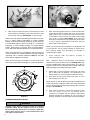
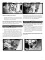
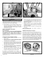
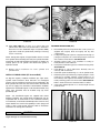
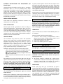
S&S Cycle, Inc.
®
Instruction 51-1049
4-10-06
Copyright © 1999, 2003, 2006
by S&S Cycle, Inc.
All rights reserved.
Printed in the U.S.A.
235 Causeway Blvd.
La Crosse, Wisconsin 54603
Phone: 608-627-1497 • Fax: 608-627-1488
Technical Service Phone: 608-627-TECH (8324)
Technical Service Email: [email protected]
Website: www.sscycle.com
Because every industry has a leader
Assembly and Installation Instructions: S&S® Big Twin Engines with 3-1/2” and
3-5/8” Bore Crankcases and Special Application (SA) 4” Bore Crankcases
DISCLAIMER:
IMPORTANT NOTICE:
S&S parts are designed for high performance, off road, racing
applications and are intended for the very experienced rider only. The
installation of S&S parts may void or adversely effect your factory
warranty. In addition such installation and use may violate certain
federal, state, and local laws, rules and ordinances as well as other laws
when used on motor vehicles used on public highways, especially in
states where pollution laws may apply. Always check federal, state, and
local laws before modifying your motorcycle. It is the sole and exclusive
responsibility of the user to determine the suitability of the product for
his or her use, and the user shall assume all legal, personal injury risk and
liability and all other obligations, duties, and risks associated therewith.
Statements in this instruction sheet preceded by the following words
are of special significance.
The words Harley®, Harley-Davidson®, H-D®, Sportster®, Evolution®, and
all H-D part numbers and model designations are used in reference only.
S&S Cycle is not associated with Harley-Davidson, Inc.
SAFE INSTALLATION AND OPERATION RULES:
Before installing your new S&S part it is your responsibility to read and
follow the installation and maintenance procedures in these
instructions and follow the basic rules below for your personal safety.
● Gasoline is extremely flammable and explosive under certain
conditions and toxic when inhaled. Do not smoke. Perform installation
in a well ventilated area away from open flames or sparks.
● If motorcycle has been running, wait until engine and exhaust pipes
have cooled down to avoid getting burned before performing any
installation steps.
● Before performing any installation steps disconnect battery to
eliminate potential sparks and inadvertent engagement of starter while
working on electrical components.
● Read instructions thoroughly and carefully so all procedures are
completely understood before performing any installation steps.
Contact S&S with any questions you may have if any steps are unclear
or any abnormalities occur during installation or operation of
motorcycle with a S&S part on it.
WARNING
Means there is the possibility of injury to yourself or others.
CAUTION
Means there is the possibility of damage to the part or motorcycle.
NOTE
Other information of particular importance has been placed in italic type.
S&S recommends you take special notice of these items.
WARRANTY:
All S&S parts are guaranteed to the original purchaser to be free of
manufacturing defects in materials and workmanship for a period of
twelve (12) months from the date of purchase. Merchandise that fails
to conform to these conditions will be repaired or replaced at S&S’s
option if the parts are returned to us by the purchaser within the 12
month warranty period or within 10 days thereafter.
In the event warranty service is required, the original purchaser must
call or write S&S immediately with the problem. Some problems can be
rectified by a telephone call and need no further course of action.
A part that is suspect of being defective must not be replaced by a
Dealer without prior authorization from S&S. If it is deemed necessary
for S&S to make an evaluation to determine whether the part was
defective, a return authorization number must be obtained from S&S.
The parts must be packaged properly so as to not cause further damage
and be returned prepaid to S&S with a copy of the original invoice of
purchase and a detailed letter outlining the nature of the problem, how
the part was used and the circumstances at the time of failure. If after
an evaluation has been made by S&S and the part was found to be
defective, repair, replacement or refund will be granted.
ADDITIONAL WARRANTY PROVISIONS:
● Consult an appropriate service manual for your motorcycle for correct
disassembly and reassembly procedures for any parts that need to be
removed to facilitate installation.
(1) S&S shall have no obligation in the event an S&S part is modified by
any other person or organization.
● Use good judgement when performing installation and operating
motorcycle. Good judgement begins with a clear head. Don't let
alcohol, drugs or fatigue impair your judgement. Start installation
when you are fresh.
(2) S&S shall have no obligation if an S&S part becomes defective in
whole or in part as a result of improper installation, improper
maintenance, improper use, abnormal operation, or any other misuse
or mistreatment of the S&S part.
● Be sure all federal, state and local laws are obeyed with the
installation.
● For optimum performance and safety and to minimize potential
damage to carb or other components, use all mounting hardware that
is provided and follow all installation instructions.
(3) S&S shall not be liable for any consequential or incidental damages
resulting from the failure of an S&S part, the breach of any warranties,
the failure to deliver, delay in delivery, delivery in non-conforming
condition, or for any other breach of contract or duty between S&S and
a customer.
● Motorcycle exhaust fumes are toxic and poisonous and must not
be inhaled. Run motorcycle in a well ventilated area where fumes
can dissipate.
(4) S&S parts are designed exclusively for use in Harley-Davidson® and
other American v-twin motorcycles. S&S shall have no warranty or
liability obligation if an S&S part is used in any other application.
1
INTRODUCTION
S&S® big twin and shovelhead engines are available in several
stages of completion. Final assembly depends upon which version
was purchased. Engine Instructions often refer to procedures
described in other S&S instructions or a Harley-Davidson® Service
Manual. These materials should be cross-referenced as necessary.
Because of the large number of instructions provided with each
engine, it is recommended that they be arranged in sequence
according to Instruction Sheet # printed in top left corner.
In most instances, assembly of S&S big twin and shovelhead
engines is similar. Exceptions will be noted where applicable. All
engines are designed for frames that accept Harley-Davidson® big
twin engines. Most fit stock Harley-Davidson® and similar frames
without modification. Some engines are significantly taller than
stock as a result of increased stroke, and may require frame
modifications. While this applies mostly to 96, 98 and 103 cubic
inch shovelhead and 103 in. big twin engines, S&S strongly
recommends trial-fitting every engine before frame is painted or
powder coated.
Because the Special Application crankcase is 1/4 inch wider than
stock, fit of exhaust, rear brake master cylinder, and foot
controls must be closely checked when installing 4 inch bore or
other engines with SA crankcases. Some components may
require modification.
WARNING
In some instances, brake master cylinder must be spaced out
from frame to clear SA crankcase. UNDER NO
CIRCUMSTANCES SHOULD MASTER CYLINDER OR BRAKE LINE
BE ALLOWED TO CONTACT EXHAUST PIPE IN FINAL
INSTALLATION. Heat transferred to brake fluid may expand
and cause brakes to seize, resulting in possible fire hazard
and loss of control of motorcycle with injury or death to rider
and others.
IMPORTANT NOTES:
● Lubrication - S&S supplies Torco® Engine Assembly Lube with
each engine. It should be used as specified in following
instructions. While other brands of assembly lube are
acceptable, other lubricants are not. In no instance should an
aerosol lubricant be substituted for assembly lube.
● Engine tuning - Ignition timing and carburetor jetting are
responsibilities of the customer. General tuning guidelines
appear in these instructions and Carburetor Instruction
Sheet #51-1012.
Picture 1
CAUTION
Incorrect ignition or carburetor tuning can cause extensive
engine damage not covered under warranty.
●
Powder coating and polishing - While S&S does manufacture
some powdercoated engines, it does not recommend having
engine parts powdercoated or otherwise modified
elsewhere. Many such procedures leave abrasive residues
which are difficult to remove completely. Also, powder
coating is cured at high temperatures that can change the
strength characteristics of some metals.
CAUTION
Glass bead and polishing residues are abrasive and can be
difficult to remove from recesses and small passages.
Abrasive residues can cause oil contamination and extensive
engine damage. Engine damage caused by powder coating,
polishing, glass bead blasting, or other modification will not
be covered under warranty.
Picture 3
Picture 2
2
Picture 4
ASSEMBLY
Picture 5
INSTALL FLYWHEEL ASSEMBLY IN CRANKCASE
(All Unassembled Engines)
NOTE - While S&S® has made every effort to insure that parts are
correct, it is the engine builder’s responsibility to confirm fit and
finish of all parts provided with engines prior to assembly. Parts
are deburred at S&S and usually require no further preparation,
but must also be inspected by installer. Individual parts should not
be removed from protective plastic wrappers until needed. After
removal from plastic, it is imperative that parts be thoroughly
cleaned and dried, preferably with compressed air. When
present, rust preventative must be completely removed.
Additionally, gaskets must be closely inspected for particles that
could become dislodged and damage engine. If assembly of
engine must be interrupted, seal openings and cover engine with
plastic to protect from destructive contaminants.
1.
NOTE - S&S does not recommend using a press to install sprocket
shaft bearings, as this can push flywheels out of true. Correct
bearing installation tools are available from Harley-Davidson®
and other sources.
2.
3.
CAUTION
Failure to observe the above may result in engine damage not
covered under warranty.
FLYWHEELS
(All Unassembled engines)
Thoroughly clean parts according to instructions previously
mentioned. Apply coat of assembly lube to bearing surface
of sprocket shaft and inner race of Timken® bearing. Install
bearing on shaft with appropriate tool. See Picture 1.
4.
5.
Apply coat of petroleum jelly to Timken® bearing installed in
Step 1. See Picture 2.
Place left side crankcase half on sprocket shaft and
bearing, insuring that connecting rods are in correct
positions. See Picture 3.
Install Timken® bearing spacer. See Picture 4.
Lubricate rollers of remaining Timken® bearing with
petroleum jelly. Apply assembly lube to bearing inner race
and sprocket shaft bearing surface. Install bearing on shaft
with appropriate tool. See Picture 5.
Carefully read S&S big twin Pinion Shaft Installations #51-1021,
S&S Connecting Rod Instructions #51-1025 and Installation
Instructions for S&S Super Stock® and Special Application big twin
Crankcases #51-1063 before proceeding.
1.
2.
Confirm that correct brass plug has been installed in end
of pinion shaft. Plug for side oiling engines (pre-1973)
will be solid. Plug for 1973-up end oiling engines will
have 3/32” hole.
Confirm pinion shaft main bearing fit. Bearing supplied
should be correct size, but must be verified by engine builder
according to procedure in S&S Crankcase Instructions, page
9. Flywheel assembly can then be prepared for installation as
described in special instructions for fully assembled S&S
flywheel sets, #51-1019.
CRANKCASES (All Unassembled Engines)
Refer to S&S Crankcase Instructions #51-1063 for information on
preparing crankcases. Additionally, blow out cam bearing and all
oil passages with compressed air.
Picture 6
3
Picture 7
6.
Picture 8 (Big Twin Models)
Lubricate pinion bearing and pinion shaft bearing boss with
petroleum jelly. Install bearing and secure with pinion shaft
main bearing snap ring. See Picture 6 on previous page.
NOTE - Pinion and sprocket shaft bearings should be correct sizes,
but it is engine builder’s responsibility to confirm flywheel
endplay, connecting rod sideplay, bearing fit, and all clearances
in unassembled engine at time of assembly. It is of particular
importance to check flywheel endplay and install different
Timken® bearing spacer if necessary. Refer to Harley-Davidson®
Service Manual for detailed explanation of required procedure.
NOTE - Harley-Davidson® has used different style pinion bearings
in various models, some requiring different snap rings. Snap ring
supplied by S&S® or identical replacement must be used with
pinion bearing supplied in S&S engine.
NOTE - Ends of snap ring are rounded on one side, sharp on the
other. Install snap ring with sharp edge out, away from flywheels.
A
1.
NOTE - In most instances S&S uses Hylomar® or Threebond® 1104
to seal crankcase. Use any sealant carefully to prevent excess
from entering engine and obstructing oil passages or
contaminating oil supply.
2.
H
C
D
G
F
E
Diagram 1
ASSEMBLE CRANKCASE HALVES
WARNING
Gasoline, lacquer thinner, and many solvents are extremely
flammable. Fumes may be explosive and toxic if inhaled.
Read and follow the manufacturers’ instructions if applicable,
and use these materials only in a well ventilated area away
from sparks and open flame.
4
Install crankcase studs and washers according to
crankcase instructions.
Note - Alignment studs for S&S generator and alternator
crankcases are in same locations B, E, & G. See Diagram 1. They
must be installed before other studs and bolts. Fit is tight, so
alignment studs must be lubricated with assembly lube, then
tapped through case assembly with plastic mallet.
3.
B
Wipe down mating gasket surfaces of crankcase halves with
lacquer thinner. Remove residue with clean, dry cloth, then
apply sealant of choice to pinion side crankcase. Take care to
avoid breather cavity and other areas where sealant might
reach inside of engine. See Picture7. Coat right main
bearing race with petroleum jelly. If applicable, allow sealant
to cure according to manufacturer’s instructions, then join
left and right crankcase halves.
4.
Tighten 5/16” case bolts and studs to 15-18 ft-lbs, 1/4” center
bolt to 10-12 ft-lbs. See Diagram 1 for identification, and
tighten fasteners in following sequence: G-B-E-F-H-D-C-A.
Install drive sprocket spacer and sprocket shaft oil seal in
main bearing race of left case.
NOTE - Because of semi-dry primary housing in shovelheads and
sealed, wet primary in big twin models, S&S installs shovelhead
sprocket shaft seals with spring facing inside, big twin seals with
spring out. See Picture 8.
5.
Allow crankcase sealant to cure per mfr.’s instructions, then
pour four ounces of motor oil over bearing end of
connecting rod assembly and into flywheel cavity. Rotate
flywheels several times to distribute oil over connecting rod
bearings. Assembly should turn freely and without binding.
Picture 9
INSTALL OIL PUMP (All Unassembled)
1.
Disassemble, clean and inspect oil pump, leaving supply drive
gear, key, and snap ring in place on shaft. Refer to S&S® Oil
Pump Installation Instructions #51-1014.
NOTE - In some instances, oil pump gears have marks. To assure
proper gear mesh, marks must align when gears installed in
pump body. See Picture 9. (Marks in picture have been
darkened. They normally appear as light punch marks.)
CAUTION
Failure to align marks may result in gear bind and possible
damage to oil pump or other engine parts.
2.
Reassemble pump, applying assembly lube to gears and gear
cavities in pump body. Remove excess to avoid
contaminating gaskets. Rotate gears as preliminary check for
bind, and to confirm that drive gear keys properly installed.
NOTE - If bind occurs, determine whether problem is with supply
or return gears by removing idler gear from either side and
rotating pump. When binding gear is removed, pump will rotate
freely. Problem can usually be corrected by rotating gear 180˚.
Picture 11
Picture 10
NOTE - Many S&S oil pumps offer more than one location for oil
supply fitting. Lowest fitting should not be used on models with
oil tank below transmission. S&S recommends stock placement
for oil supply fitting in these bikes. See Picture 10.
CAUTION
Routing oil supply line to lowest fitting on models with oil
tank below transmission could allow air to enter oil pump
under certain circumstances, causing air lock, loss of
lubrication and engine damage.
3.
Apply assembly lube to oil pump driveshaft and driveshaft
bushing in crankcase. See Picture 11. Install oil pump in
normal fashion, placing pump drive gear #33-4230 over
driveshaft as shaft is passed through crankcase bushing.
Refer to S&S Oil Pump Instructions and Harley-Davidson®
Service Manual as needed.
NOTE - A dab of Hylomar® or other thin gasket sealer in corners
may be used to hold gaskets in place. Otherwise gaskets should
be installed dry.
Picture 12A
5
Picture 13
Picture 12B (Correct Installation)
4.
Install driveshaft gear key and snap ring.
7.
NOTE - Be sure drive shaft key and snap ring are installed
properly, paying particular attention to snap ring. If not installed
correctly, “sprung,” or otherwise damaged, snap ring may come
off or allow gear key to come out. See Pictures 12A & B.
CAUTION
Loss of oil pump drive gear snap ring or key will result in
disengagement of oil pump causing loss of oil pressure and
extensive engine damage.
5.
INSTALL PINION GEAR, SPACER AND NUT
(All Unassembled)
1.
Loosely install 2 ea. 1/4-20 x 1-1/2” top oil pump bolts,
followed by pump cover and 4 ea. 1/4-20 x 2-3/4” mounting
bolts. Do not tighten at this time.
NOTE - 1/4-24 bolts supplied with oil pump kit are not used in
S&S® engines.
While turning oil pump drive gear to check pump for
binding, gradually tighten 4 2-3/4” bolts in X-pattern to final
spec. of 8-10 ft-lbs. See Picture 13. Carefully tighten short
bolts “by feel” with thin box end wrench.
Picture 14 (Note Chamfer)
6
With chamfer on oil pump drive gear facing in towards
shoulder on pinion shaft (See Picture 14), install oil
pump drive gear and key on pinion shaft, followed by
drive gear spacer.
CAUTION
Installing gear backwards can result in a stress riser and cause
shaft to break.
2.
6.
Prime pump by removing oil pump check valve ball assembly
(See illustration on page 15 in Oil Pump Instructions) and
injecting clean motor oil into pump supply fitting while
turning oil pump drive gear. (A large plastic squeeze bottle
works well for priming pump.) Replace check ball, spring,
and cap after oil fills check valve cavity.
Apply thin film of red Loctite® #271 to pinion shaft taper and
threads. Install pinion gear, key and nut on pinion shaft and
tighten nut to 50 ft-lbs. See Picture 15. S&S Connecting Rod
Checking Pin, part #53-0002, can be used to prevent
flywheels from turning as pinion nut tightened on shaft.
Picture 15
Picture 16A
Picture 16B
NOTE - Drive gear spacer will not completely fill space between
oil pump drive gear and pinion gear. A gap of up to .125” may
exist and is normal. Engine rotation keeps oil pump gear in place
during normal operation. Spacer prevents gear and key from
becoming disengaged if engine rotated backwards.
INSTALL BREATHER GEAR, CAMSHAFT, AND GEAR
COVER (All Unassembled)
CAUTION
Installing pinion gear or nut without Loctite® can cause
damage to shaft, nut, or other parts.
3.
In Generator engines only, install intermediate and circuit
breaker drive gears, and spacers if applicable.
NOTE - To increase bushing surface area, S&S® intermediate
and circuit breaker drive gears do not utilize spacers. Correct
end play of .003-.007 in. must be established using shims
provided with gears.
Timing mark on circuit breaker drive gear must align with mark
on pinion gear. Other mark on pinion gear must be positioned
to align with mark on camshaft gear when camshaft installed.
See Picture 16A.
1.
Thoroughly clean and dry all parts including camshaft
lockwasher and thrust washer. Carefully inspect breather
gear for burrs and remove as necessary. Inspect edges of
crankshaft breather for burrs and smoothness. Cam thrust
washer and breather gear shims should be correct size, but
endplay of camshaft and breather gear must be verified by
customer. Refer to S&S Camshaft Instruction Sheet #51-1026,
Gear Cover Instructions #51-1032, and Harley-Davidson®
Service Manual as necessary.
2. Apply light coat of Vaseline® to cam bearing, and coat of
assembly lube to cam lobes, camshaft lockwasher,
thrustwasher, breather gear, and to breather gear cavity
inside engine.
3. Place camshaft lockwasher in case with ears down and flat
edge towards rear of engine. See Picture 17.
4. Install thrust washer over end of cam and place assembly in
engine. During installation, rotate engine so marks on cam
gear and pinion gear align. Second mark on cam gear must
be at eight o’clock position. In Generator engines, second
mark on pinion gear must be at two o’clock position to align
with mark on circuit breaker drive gear.
5. Install breather gear and shim, aligning breather gear timing
mark with eight o’clock mark on cam gear. See Picture 16B.
6. In Generator engines only, install breather screen and
separator (not supplied by S&S) if desired.
7. Use connecting rods to rotate flywheels and insure gears
rotate freely. Apply assembly lube to ends of shafts and
meshing surfaces of gears and remove excess.
8. Apply assembly lube to gear cover bushings.
9. Clean gasket surfaces on engine and gear cover with lacquer
thinner, wipe dry, and apply light film of Hylomar® or
preferred sealant to both sides of gasket.
10. Install gasket and cover and tighten screws to 10-12 ft-lbs.
NOTE - Gear cover should slide smoothly over alignment dowels
and must not be forced. Confirm that gasket material does not
overlap oil passages in crankcase and gear cover. See Picture 18.
Picture 17
7
Picture 19
Picture 18
CAUTION
Having to force gear cover indicates alignment problem.
Problem must be identified and corrected before operating
engine. Operating engine with forced gear cover could result
in broken pinion shaft or other engine damage.
11. Rotate flywheels to check for binding. If present, cause of
bind must be determined and corrected. If assembly rotates
freely, pour approximately four ounces of oil into gear
compartment after allowing crankcase sealant to cure per
manufacturer’s instructions.
INSTALL LIFTERS AND LIFTER GUIDES
(All Unassembled)
NOTE - S&S® installs HL2T (Hydraulic Lifter Limited Travel) Kit in
lifters in assembled big twin engines. HL2T Kit is included with
unassembled big twin engines, but not installed. S&S
recommends using kit. If desired, install kit according to
Installation Instructions for S&S Hydraulic Lifter Limited Travel Kit
#5038 before proceeding.
Install big twin lifters and guides as follows:
1. Remove oil pressure sending unit behind rear lifter
guide opening.
2. Identify gaskets for front and rear lifter guides and apply
thin film of Hylomar® or preferred sealant to both sides of
each. Gaskets are not interchangeable.
3. Coat lifter guide bores with assembly lube and insert lifters.
Work lifters back and forth in guides, assuring that they
move freely and without binding. Apply assembly lube to
lifter rollers and remove any excess.
4. Thoroughly clean and dry gasket surfaces of lifter guides and
crankcase. Place rear gasket on crankcase, assuring that oil
hole in gasket aligns with passage in case.
5. Taking care not to dislodge or contaminate gasket, lower
rear guide assembly into place. Fingers can be inserted
through front lifter guide opening to support lifters.
All reference to Harley-Davidson® part numbers is for
identification purposes only. We in no way are implying that
any of S&S® Cycle’s products are original equipment or that they
are equivalent to the corresponding Harley-Davidson® part
number shown.
8
Insert Harley-Davidson® alignment tool H-D® #33443 or
similar tool from other source in lifter guide screw hole by oil
passage. See Picture 19. Install and tighten guide screws in
three remaining holes. Remove tool, install fourth screw, and
tighten all to 10-12 ft-lbs.
7. Repeat procedure for front lifter-guide assembly.
Assembly lube will usually hold lifters in guide during
installation. If resistance encountered, check to see if lifter
has become dislodged.
8. Apply thread sealant to threads of oil pressure switch
and install.
Install shovelhead lifters and guides according to
manufacturer’s instructions.
6.
CRANKCASE VENT (Big Twin Engines)
Before further assembly, it must be decided whether engine is to
vent crankcase pressure out crankcase, cylinder heads, or both.
S&S big twin engines are compatible with both, and S&S
recommends dual venting whenever possible, especially with
four inch bore engines. If different gear cover is installed by
customer, for crankcase vent or dual venting it must be of HarleyDavidson® ‘92-older and used with correct gasket. ‘93-up lower
rocker covers and correct gaskets must be used for cylinder head
venting and dual vent arrangement. See Pictures 20 & 21.
Center sections with umbrella valves must also be used.
1993-Later
1992-Earlier
Picture 20
1992-Earlier
1993-Later
Round areas shown in both valve reliefs.
Picture 22
Picture 21
Engines ordered for ‘84-’92 year group will require the
following additional parts for dual venting: S&S® air cleaner
backplate #17-0336 and hardware packet #17-0439. Both are
available from S&S.
NOTE - 1992 was a transitional year for some Harley-Davidson®
models. While cylinder head venting was introduced in 1992,
many motorcycles sold as 1992 models retained crankcase
venting. Gear cover, gear cover gasket, lower rocker covers, and
lower rocker cover gaskets must be identified by year group to
determine possible vent arrangements.
INSTALL PISTONS AND CYLINDERS
(All Unassembled)
1.
2.
3.
NOTE - Using ‘93-up gear cover or gasket on S&S big twin engines
set up to vent out crankcase will result in large oil losses out
crankcase vent opening.
NOTE - Using ‘91-older lower rocker covers or gaskets in engines
set up for cylinder head venting will obstruct cylinder head vent
passages, causing oil leakage and possible damage to other
components. See Picture 22.
4.
5.
NOTE - If ‘93-up lower rocker covers are used in engine set up for
crankcase venting only, oil seepage past cylinder head vent
passage inserts may occur. It is recommended that ‘91-older lower
rocker covers be used in engine set up for crankcase venting only.
6.
Install vent hardware (big twin):
1.
For crankcase and dual venting, install 45˚ elbow, #31-2022,
in crankcase vent opening per S&S Crankcase Instructions
#31-0000M. If engine to vent out cylinder heads only, plug
crankcase vent opening with socket head pipe plug
#31-2023. Steel fittings such as elbow and plug must be
coated with anti-seize thread sealant such as Slic-Tite®
or Teflon® tape before installation in crankcase or
cylinder head.
7.
8.
9.
2.
For crankcase venting only, install threaded inserts #90-4026
in cylinder head air cleaner mounting bolt holes. See
Carburetor Instruction Sheet #51-1012.
Note- Shovelhead engines vent out crankcase only.
Identify front and rear pistons according to “Piston
Installation” section in S&S Pistons Instruction Sheet
#51-1028. Piston Series number will appear on box
containing piston assembly.
Inspect pistons, especially areas around machined surfaces
such as ring grooves and wristpin holes, for burrs. De-burr as
necessary, taking care to remove particles that could become
dislodged inside engine.
On big twin engines that will be operated in extremely hot
climates such as American South, Southwest, or areas with
only low octane gasoline available, carefully round sharp
edges on piston dome and in combustion chamber. A die
grinder and small, flexible sanding wheel work well for this.
See Picture 22.
Measure ring end gaps and adjust as necessary. See S&S
Piston Instruction Sheet #51-1028, “Ring Installation” for gap
specification applications.
Thoroughly clean cylinders, pistons, rings, wristpins, and
wristpin retainers in solvent, then hot, soapy water. Take
special care to flush oil passages, and pass clean, white cloth
back and forth through wristpin bores. Dry all with
compressed air and place on clean, dry surface.
S&S recommends installing all cylinder base gaskets dry.
Builders who prefer sealant may use sealant of choice on
shovelheads, but big twin gaskets are different material and
must be installed dry. Be sure holes in gaskets align with
cylinder base dowels and oil holes.
Install rings on pistons as described in Piston Instruction
Sheet. S&S recommends covering cylinder studs with 3/8” I.D.
fuel line to protect rings until cylinder installed.
Lubricate connecting rod wristpin bushings with light coat of
assembly lube. Install rear piston, wristpin and retainer on
connecting rod per piston instructions.
If big twin cylinders, install cylinder head alignment dowels
in cylinder.
NOTE - Tight clearances resulting from reinforced S&S cylinder
design require that S&S shovelhead base nuts and two head bolts
(ones nearest exhaust pipes on cam side of engine) be inserted
and held in place as cylinder lowered over studs. See Instructions
for S&S Sidewinder® Big Bore Cylinders No. 1000, page 12.
9
Picture 24
Picture 23
10. Apply very light film of motor oil to piston skirts and
cylinder bores and install rear cylinder. Refer to Installation
Instructions for S&S® Sidewinder® Big Bore Cylinders #1000,
pages 12-13. Install rear cylinder head, referring to following
section as necessary.
PUSHROD PREPARATION (All)
1.
2.
NOTE - IOn big twin engines, if engine builder chooses to install
front cylinder before installing rear head, rear cylinder should be
temporarily secured with head bolt and washers. If cylinder not
secured, piston can lift cylinder and disturb base gasket if
flywheels rotated.
11. Repeat piston installation for front cylinder and
cylinder head.
INSTALL CYLINDER HEADS (All Unassembled)
For big twin engines, complete installation per Super Stock®
Cylinder Head Instruction Sheet #51-1042. For shovelhead
engines, refer to Installation Instructions for S&S Sidewinder® Big
Bore Cylinders #51-1014. Note that shovel intake manifold and
top end oil supply lines should be installed before headbolts
tightened on shovelhead engines. If S&S shovelhead heads used,
rocker cover assemblies must be installed using cap screws
provided by S&S.
3.
4.
5.
6.
7.
8.
Disassemble pushrods and pushrod tube covers (covers not
supplied with engine). Clean thoroughly and dry with
compressed air.
For big twin style pushrods, blow compressed air through oil
passage in each pushrod to confirm that passage is clean and
free of debris and obstruction. See Picture 23.
Assemble pushrod tube cover assemblies according to
Harley-Davidson® Service Manual.
Insert pushrod tube O-ring spacers in lifter blocks (big twin).
See Picture 24.
Install O-rings or corks in lifter blocks. Normally corks are
used only with shovelheads.
Install thick pushrod tube O-rings or corks in cylinder heads.
Determine pushrod placement by comparing lengths of each
pushrod (not including adjuster). Longest pushrod is for
front exhaust, next longest for rear exhaust, shortest for rear
intake, remaining pushrod for front intake. See Picture 25.
Refer to Pushrod Instruction Sheet #51-1035 as needed.
Screw pushrod/lifter adjusters in to shortest length and set
pushrods aside.
NOTE - S&S shovelhead engines are supplied with several
different camshafts. S&S cylinder heads assembled by S&S are
compatible with all. Stock heads are not. If different camshaft,
non-S&S heads, or S&S heads assembled by other source are used,
engine builder must confirm lift capability of valve springs and
collars as well as valve-to-valve clearance. Refer to Installation
Information for S&S big twin camshafts.
CAUTION
Failure to establish correct clearances can cause extensive
engine damage not covered under warranty.
Picture 25
10
ROCKER
ARM/PUSHROD
ADJUSTMENT (big twin)
INSTALLATION
AND
NOTE - S&S pushrods are designed with emphasis on strength.
Weaker pushrods may flex under load, resulting in loss of power,
increased cranking compression, or detonation.
1.
2.
Rotate flywheels in direction of normal engine rotation until
both lifters for front cylinder at lowest position on camshaft.
Front piston will be at or near TDC on compression stroke
when lifters in correct position.
Identify pushrods as explained in Step 6, “Pushrods” section.
Hold pushrod tube for front intake in place and pass correct
pushrod, adjuster end down, through cylinder head and
pushrod tube. Repeat for front exhaust.
NOTE - Some engine builders prefer to install and adjust pushrods
one at a time, beginning with intake.
Picture 26
3.
INSTALL LOWER ROCKER COVERS (All big twin)
Rocker covers must be installed with hardened flat washers and
grade 8 bolts of proper length. Correct hardware is available
from aftermarket suppliers and Harley-Davidson®.
Note - Consult S&S® shovelhead Cylinder Head instruction sheet
#00-9001 for assembly and installation of shovelhead cylinder
heads and rocker cover assemblies.
CAUTION
Lockwashers should not be used inside engine. Lockwashers
cut metal surfaces and can cause damaging metal particles to
be distributed through engine by circulating oil.
1.
2.
All parts must be clean and dry. To install, place lower rocker
cover gaskets on cylinder head with silicone bead facing up.
A small amount of Hylomar® or other thin gasket sealant
may be used in corners to hold gasket in place on head. No
other sealant should be used.
Place lower rocker cover on gasket and cylinder head and
hold loosely in place with 1/4” bolts and flatwashers. Verify
that cover is positioned so as not to interfere with valve
spring operation (See Picture 26), then tighten bolts to
10-13 ft-lbs as described in Harley-Davidson® service
manual. In cases where clearance between cover and spring
is insufficient, bolts may be loosened and cover
repositioned slightly to gain clearance. It is also possible to
take cover off engine and remove small amount of metal
from cover to increase clearance. After clearance
confirmed, install two short 5/16” bolts and washers on left
or drive side of engine and tighten to 15-18 ft-lbs.
CAUTION
Operating engine without sufficient clearance between valve
spring and rocker cover will cause engine damage not
covered under warranty.
4.
Place front rocker arms in lower rocker cover and install
shafts, confirming that reliefs in shafts align with bolt holes
in rocker covers. Rocker arms must sit squarely on valve tips.
If not, loosen rocker cover bolts and reposition cover slightly
to obtain correct alignment. Do not overlook valve springcover clearance as described previously. With proper rockervalve stem alignment and valve spring-rocker cover
clearance confirmed, install two 5/16” bolts and flat washers
in lower cover and tighten to 15-18 ft-lbs.
If HL2T kit is used, pushrods must be adjusted according to
Installation Instructions for S&S Hydraulic Lifter Limited
Travel Kit #51-1039.
NOTE - Recommended pushrod adjustment with kit is 3 flats
or 1/2 turn shorter than zero lash with lifters completely
bled down.
Pushrods will be noisy if set at zero lash. If HL2T kit not
used, adjust pushrods according to S&S Pushrod Instruction
Sheet #51-1035.
5. Install middle and upper rocker covers and gaskets on
front head. If applicable, install center sections with
umbrella valves towards center off engine. Insure that
small center gasket in lower cover does not become
dislodged. A dab of grease or adhesive may be used to
hold gasket in place. Tighten screws to 10-13 ft-lbs. Install
pushrod cover retainer clips.
6. Rotate flywheels until rear piston reaches TDC on
compression stroke (315 flywheel degrees past front piston
TDC) and both rear lifters are in lowest position on cam.
Repeat procedure for installing pushrods, rockers, and
covers, installing longest remaining pushrod in exhaust.
7. After pushrod adjustment completed per instructions, rotate
flywheels several revolutions in direction of normal flywheel
travel to confirm that engine turns freely.
NOTE - Do not force engine. If resistance encountered, determine
and correct cause before continuing.
CAUTION
3.
Clean rocker arms and shafts and dry with compressed air.
Coat rocker shafts, rollers, bushings, valves and pushrod tips,
and ends of rocker arms with assembly lube.
Forcing engine against resistance may cause damage not
covered under warranty.
11
PUSHROD INSTALLATION AND ADJUSTMENT (All
Shovel Style)
Shovelhead pushrod installation will be similar to procedures
described in Steps 1, 2 and 6 of preceding section, except
pushrods will be installed in pushrod tubes and inserted into
rocker boxes after O-rings or corks installed. Adjustment will
depend upon type and brand lifter used. Refer to HarleyDavidson® Service Manual and instructions provided by lifter
manufacturer. In some instances, S&S® Pushrod Instruction Sheet
#51-1035 will prove helpful.
In general, excessive ignition advance will cause engine to kick
back against the starter during start-up and “buck” when ridden
at steady speed with partial throttle. An advanced condition can
also cause pinging or ignition knock and possible piston damage.
These symptoms may not be noticed if electronic ignition with
“soft” advance curve is used.
Excessive ignition retard causes sluggish performance and severe
overheating with possible subsequent damage to the engine,
and must also be avoided. Immediate or rapid exhaust pipe
discoloration is usually a sign of retarded ignition timing.
INSTALL INTAKE MANIFOLD
Install manifold as explained in Carburetor Installation and
Jetting Instruction Sheet #51-1012.
FINAL INSTALLATION
Finished engine should be installed in frame according to
authorized Harley-Davidson® Service Manual. Clean gas and oil
tanks thoroughly before installing, and be sure all traces of
solvent are removed. Old oil lines should be flushed or replaced,
and a new oil filter installed. With engine installation complete,
carburetor and air cleaner assembly can be installed according to
Carburetor Instruction Sheet #51-1012.
IGNITION TIMING
S&S recommends using electronic ignition with adjustable
advance curve in Super Stock® and Super Sidewinder® engines.
Adjustable curve permits slowing rate of advance to control or
eliminate pinging under heavy load or when elevated
temperatures or poor quality gasoline encountered. Install
ignition according to manufacturer’s instructions. Leave spark
plugs out while static timing to ease flywheel rotation.
Flywheels in S&S big twin engines have three timing marks:
( I F ) = Front cylinder firing mark, 35˚ degrees before TDC
with vertical line in center of hole. See caution below.
●R ) = Rear cylinder firing mark, 35˚ degrees before TDC
(●
with dot in center of hole.
( T:F) = Front piston, Top Dead Center with colon (:) in center
of hole.
Most fully electronic ignitions are timed at TDC. Points and other
ignitions with mechanical advance are timed at front cylinder
firing mark. With correct mark centered in timing inspection
hole, ignition at full advance will occur 35˚ before TDC. S&S,
however, recommends setting initial timing at 32˚ BTDC.
This can be accomplished by setting the ignition to fire when
flywheel mark is leaving timing inspection hole on left side.
CAUTION
Operating big twin engine with mark centered in hole at 35˚∞
can cause detonation and damage to engine not covered
under warranty.
Additional minor adjustment of timing may be required due to
poor quality gasoline, extremely hot climate, etc., but ignition
should occur between 28˚ and 32˚ BTDC when fully advanced,
and engine closely monitored for heat build-up.
12
CAUTION
Pinging or ignition knock is an early sign of detonation and
possible impending engine damage. Should pinging occur,
the throttle must be backed off and the cause determined and
corrected. Excessive retard is less obvious but equally
destructive. For that reason, final timing should be confirmed
with a timing light or other accepted procedure.
LUBRICATION
S&S recommends the use of Mobil 1 VTwin 20W-50 synthetic oil
in our engines.
Perform following steps before starting engine:
1. Connect oil lines according to Harley-Davidson® Service
Manual. Be sure clamps are tight and lines routed to avoid
kinks and hot surfaces such as exhaust pipes.
2. Place correct amount of oil in tank.
3. Remove any remaining air from oil pump.
CAUTION
Air trapped in oil pump can prevent oil from circulating
through engine, causing extensive damage to engine.
WARNING
Oil on tires or brakes could cause loss of control of motorcycle
resulting in serious injury to operator and others. Inspect tires
and brakes to insure both are clean and free of oil prior to
operating motorcycle.
4.
Oil pressure should be confirmed with a quality gauge.
Pressure varies at idle, but should be high enough to keep oil
pressure warning light off. Pressure at operating
temperature should be 12-35 PSI at highway speeds.
SPARK PLUGS
Install spark plugs with gap recommended by ignition
manufacturer. Typically, .035-.045” is recommended for electronic
ignitions, .022” for points. S&S has used the following sparkplugs
in big twin engines with good results: Autolite® 4265, Champion®
RN12YC, Harley-Davidson® 5R6A, and NGK BPR 4ES. In general,
same sparkplugs work for shovelheads if equipped with S&S
shovelhead cylinder heads or 1975-1984 Harley-Davidson®
cylinder heads designed for long reach plug.
Exhaust Systems
● Drag Pipes - While drag pipes can be used with good results
to establish performance guidelines on 1985 engines, they
are generally not recommended for big twin engines in
street applications. Big twin engines are easier to carburate
with muffled systems.
● Muffler systems - Most stock and many aftermarket exhaust
systems are too restrictive and made exclusively for looks
with little consideration given to performance. Avery good,
economical street system for big twin engines consists of the
stock header pipes with the crossover tube and set of low
restriction mufflers. S&S® offers a series of mufflers that can
be used with stock header pipes that work very well. This
combination will typically produce more horsepower and
torque than drag pipes in the midrange. Since the midrange
is where the vast majority of normal driving occurs, it makes
this system ideal for the street.
START-UP AND BREAK-IN
NOTE - S&S engines require premium gasoline (octane 91 or
higher) for best performance. Octane boosting gasoline additives
may be necessary with marginal gasoline.
3. Break-in according to following guidelines:
A.
1.
2.
3.
4.
1.
Start engine according to procedure in Carburetor
Instructions. If S&S carburetor supplied with engine is used,
jetting should be approximately correct and engine can be
started and fine tuned according to procedure in carburetor
instructions. Altitudes greater than approximately 4000 feet
above sea level will probably require leaner jets unless high
altitude jetting specified at time of order. If other carburetor
used, it must be rich enough to provide sufficient fuel. In any
case, engine must not be allowed to idle for an excessive
period of time during initial start-up.
Vary speed and do not lug engine.
Change oil and filter at 50 miles and keep outside
of engine clean.
Do not subject engine to unusual stress or load as
with sidecar or trailer.
Avoid hard acceleration, especially before engine
has reached operating temperature, and do not lug
engine. Vary engine speed and avoid maintaining
steady speed for long distances.
NOTE - On shovelhead engines, cylinder base nuts and head bolts
should be retightened after engine has been run and reached
normal operating temperature. Do not tighten or retorque big
twin head bolts.
B.
For next 500 miles, engine may be taken to 3500 RPM or
approximately 65 MPH (depending upon gearing) for
brief periods. Speed should be varied, and lugging and
heavy traffic avoided. Change oil and filter at end of
first 500 miles.
C.
Modest increases in speed are permissible during next
2000 miles, but do not exceed 3500 RPM. Engine should
not be given full throttle, and heavy loads such as
trailers and sidecars avoided. Some operation at in-town
speeds (40-45 MPH) is recommended, although
prolonged idling, lugging and heavy traffic should still
be avoided. Change oil and filter at 500 mile intervals
until 2500 miles.
D.
The following is mandatory at 2500 miles and
thereafter: HAVE FUN! Oil and filter should be
changed every 2000 miles after break-in, more often if
oil appears dirty or engine is subjected to extreme
temperatures or dusty conditions, ridden for only short
periods of time, or frequently operated in heavy traffic.
CAUTION
Low octane gasoline and hot weather can cause detonation
and extensive engine damage. Never try to power through
ignition knock (“ping,” “rattle,” etc.) by opening throttle.
First 50 miles are critical for new rings and pistons. Most
engine damage occurs during this period. Keep heat
down by avoiding heavy traffic and not exceeding 2500
RPM or approximately 50-60 MPH, depending upon
gearing, during this time. During brake in:
CAUTION
Prolonged idling with inadequate air flow over engine will
cause overheating and permanent damage to engine. For this
reason, heavy stop and go traffic and extended idling should
be avoided during break-in.
To avoid damaging heat build-up, engine must not be
subjected to excessive load or strain during break-in period.
Lugging the engine should always be avoided.
PERFORMANCE
Properly tuned and equipped with an efficient exhaust, most S&S
big twin engines produce 1 to 1.1 horsepower per cubic inch at
the rear wheel. The following should be considered in the event
of unsatisfactory dynamometer results or other poor
performance: exhaust system, carburetor jetting, and ignition
timing. Other factors including climate, oil viscosity, gear ratio,
dragging brakes, worn drive chains or belts, gross vehicle weight,
and tire or clutch slippage can affect performance.
CAUTION
Lugging and excessively low idle can cause engine damage.
2.
Observe for gas and oil leaks.
S&S has carefully chosen the components in each engine for
reliable high performance use. Substituting another
manufacturer’s product, even one as seemingly insignificant as air
cleaner assembly or pushrods, for one provided by S&S can result
in loss of horsepower, reliability, or both. Additionally, extremely
heavy motorcycles or loads combined with different gear ratios
(61 and 65 tooth rear pulleys) used on newer Harley-Davidson®
models will hamper overall performance.
13
TECHNICAL SUPPORT
2. Engine turns over but will not start
A. Compression low - Check pushrod adjustment.
S&S® Cycle strives to manufacture quality products well suited for
their intended use. In most cases, problems with completed
engines are caused by parts or circumstances beyond S&S’s
control. The following section will be helpful in dealing with
many such problems. In the event additional technical support is
required, please contact the S&S Technical Services Department
at 608-627-TECH (8324), FAX 608-627-0766, or E-mail
[email protected].
B.
No ignition - Confirm spark at spark plug. If weak or
absent, turn on lights to see if battery has good
charge. If lights dim, check wiring connections at
battery. If connections good, recharge or replace
battery. If lights bright but spark absent or weak, check
wiring connections at ignition switch, sensor, module,
and coil. If connections good but no spark, check for
open circuit breaker/blown fuse resulting from wiring
short. If none of above correct problem, troubleshoot
ignition system according to manufacturer’s
instructions and check timing.
C.
No fuel - Refer to troubleshooting tips on pages 13-14 in
carburetor instructions.
TROUBLESHOOTING
1. Starter will not turn engine over.
NOTE - New engines are hard to turn over because of friction
between tightly fit parts. They will loosen considerably after
approximately 2000 miles. Most 1990-up gear reduction starters
in good condition will start S&S engines with little difficulty.
1984-1989 model starters are less powerful and may labor, but
should work for most applications if in good condition. Hitachi®
and Prestolite® shovelhead starters in good condition are
adequate for most shovelhead engines up to 98 cubic inches. 103
cubic inch may require heavy duty or modified stock starter.
Accel® Motorcycle Products manufactures “high torque” field
coils that improve performance of Prestolite® starters. The
following should also be considered when engine is difficult to
turn over.
A. Battery weak - Battery should be top of the line,
premium brand in new or like new condition with full
charge. S&S has had good results with Yuasa® YuMicronCX and YTX20 series sealed batteries.
B.
C.
Worn or malfunctioning components in starter system:
starter motor, relay, solenoid, or drive.
Oil viscosity too heavy for climate.
D.
Hydraulic lifters incorrectly adjusted.
E.
Other brand pushrods substituted for S&S pushrods,
resulting in elevated cranking compression.
In situations where new engine is hard to turn over due to
friction and not other problem:
A. “Bump” starter button until compression stalls piston
near TDC. Turn off ignition switch for 10 seconds to
allow starter to cool and battery to recover.
B.
If engine cold, prime carburetor with accelerator pump
and lift enrichener lever. Temperatures below 45˚F. may
require 3-5 additional “squirts” from accelerator pump
for engine to start quickly. Refer to carburetor
instructions for additional information.
C.
Switch ignition on, engage starter and lower enrichener
lever as engine warms.
3.
Engine starts but runs poorly
A. Erratic fuel supply or poor carburetor tuning - Refer to
carburetor instructions. Pay particular attention to gas
tank venting. Audible hiss when cap loosened
indicates vent problem.
B.
Ignition timing incorrect.
C.
Loose wiring connection or faulty circuit breaker or
ignition switch.
D. Ignition malfunction. Check for faulty ignition
sensor, module, coil, condenser, intermittent
electrical short, etc.
F.
Intake manifold air leak; refer to carburetor instructions.
G.
Valves not seating due to incorrect pushrod adjustment.
H.
Fouled spark plugs caused by overly rich carburetor
jetting, leaving enrichener on too long, or weak
ignition.
I.
Contaminated or poor quality gasoline.
NOTE - Inferior or contaminated gasoline can cause hard starting,
power loss, and erratic performance. When poor quality gas is
suspected, several tankfuls of gasoline obtained from a source
known to be good should be run through the engine and then
used on a regular basis if improvement is noted. In some
instances, spark plugs one heat range colder than normal may
improve performance with marginal gasoline. Some gasoline
additives currently in use by petroleum companies cause hard
starting, power loss, and other problems blamed on the engine
or state of tune.
4. Low oil pressure
If air removed from pump before start-up, low oil pressure is
usually related to part other than engine or oil pump.
A.
Check for worn bushings and excessive operating
clearances in old parts such as rocker assemblies or
gear cover.
B.
If gear cover removed or replaced for any reason, check
that oil passage holes between gear cover, gasket, and
crankcase line up correctly. Gasket must not overlap
passage at all.
C.
If non-S&S parts installed, closely examine them for
excessive running clearance or possible manufacturing
defect, especially porosity in pinion oil passage of gear
cover.
NOTE - Starting procedure can vary according to weather,
altitude, carb tuning, and ignition system. Regardless, engine
must be in good state of tune for reliable starting.
D. If engine remains difficult to start, check compression
with professional quality screw-in gauge as follows:
with gauge in place, remove other spark plug, hold
throttle wide open, and turn engine over rapidly with
starter. Reading below 185 PSI is normal. If reading
above 185 PSI, contact S&S Technical Services Dept.
14
5. Noisy lifters
NOTE - In new installation, hydraulic lifters can take extremely
long periods of time to “pump up.” Motorcycle should be ridden
during this time and prolonged idling avoided. Brisk acceleration
may help stubborn lifter to pump up. If noise persists, consider
the following:
7.
A.
Retarded ignition timing.
A. Improper lifter/pushrod adjustment in customerassembled engine. See HL2T Kit Instructions #51-1039
and Pushrod instructions #51-1035.
B.
Carburetor jetting too lean.
C.
Intake manifold/carburetor air leak. If VOES not used,
hose fitting in manifold must be plugged.
B.
D.
Spark plug heat range too hot.
E.
Restricted oil supply.
F.
Insufficient air flow from running engine too long at
stop or in slow-moving traffic.
C.
6.
NOTE - Oil temperature up to approximately 220˚F is normal.
Prolonged temperature of 240˚F or greater is excessive and
should be investigated. Consider following possible causes.
Silicone or other foreign matter obstructing applications
crankcase oil screen assembly. Refer to crankcase
instructions page 3, section 3-B. Remove, inspect, and
clean screen as necessary.
Low oil pressure - Refer to number 5 above and Service
Bulletin 15 in Oil Pump Instructions.
Excessive crankcase pressure as evidenced by multiple
oil leaks or filler cap blowing out of oil tank when
engine started.
A.
Oil lines kinked or installed incorrectly. Check oil return
line and crankcase vent hose.
B.
‘91-earlier lower rocker cover gaskets used in engine
that vents out cylinder heads only. Early gasket will
pressurize oil tank via vent line, causing cap to blow out.
Engine expels excessive oil through crankcase breather
A.
Oil lines installed incorrectly. Connecting primary
housing scavenge fitting to tee in oil tank vent line can
drain contents of oil tank into crankcase. Scavenge
fitting should be removed from engine having open or
sealed primary, and hole plugged. Oil will also drain into
crankcase if feed line from tank connected to return
fitting on pump.
B.
If gear cover has been removed, check to see that
correct gasket was used for reinstallation. Gear cover
gasket must be ‘92-older style if crankcase venting used.
C.
If S&S® gear cover replaced with other brand, check
closely for manufacturing defects and confirm that new
cover is compatible with crankcase venting. (See
Vent/Breather System comments on page 7.)
D.
Chain oiler adjustment screw replaced with standard
machine screw in Model 6250 oil pump. 6250 pump is
seldom used on engines except with certain generator
crankcases. 6250 pump can be identified by chain oiler
adjustment screw on side of pump body.
10. Vibration
NOTE - Vibration can have many causes outside engine.
Following should be ruled out before suspecting engine.
A.
Tires/wheels out of balance or not round.
B.
Engine or transmission not square in frame.
C.
Motor mount loose, or worn rubber mount.
D.
Drive sprockets worn or out of alignment.
E.
Drive belt/chain worn or out of adjustment.
F.
Rear cylinder ignition timing different than front (for
ignition with independent timing adjustment for front
and rear cylinders).
G. Ignition module malfunction.
H. Contaminated or poor quality gasoline.
NOTE - S&S has found that vibration caused by poor quality
gasoline can in some instances be reduced or eliminated by using
spark plugs one heat range colder than normally recommended.
I.
Frame bent or broken.
J.
Exhaust system or other heavy component mounted
incorrectly or inadequately supported. Check for loose
or broken support bracket.
8. Exhaust smoke
A.
Restricted oil return line.
B.
Carburetor overly rich or enrichener used excessively.
C.
Excessive lubrication applied to cylinder wall/piston
rings during assembly.
D.
Piston rings installed incorrectly or damaged
during installation.
9. Overheating
15
Because every industry has a leader