1
Repair Manual
ID-4 Instant
Photographic ID System
January 1993
Americas Business Center
Technical Services
201 Burlington Road
Bedford MA 01730
TEL: 1.781.386.5309
FAX: 1.781.386.5988
[This page intentionally blank]
Polaroid ID-4 Service Manual
ID-4 INSTANT IDENTIFICATION SYSTEM
SERVICE MANUAL
TABLE OF CONTENTS
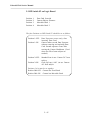
SECTION 1
OVERVIEW & SPECIFICATIONS
SECTION 2
SYSTEM COMPONENTS & THEORY OF OPERATION
SECTION 3
DIAGNOSTICS & TROUBLESHOOTING
SECTION 4
DISASSEMBLY, ADJUSTMENTS & WIRING
APPENDIX
SCHEMATICS
[This page intentionally blank]
Polaroid ID-4 Service Manual
SECTION 1
OVERVIEW & SPECIFICATIONS
1-1
Polaroid ID-4 Service Manual
Notes
1-2
Polaroid ID-4 Service Manual
A. System Overview
•
The Polaroid ID-4 System is designed to produce highly
secure photo-identification cards. The System includes a
camera, laminator, and diecutter. These fit onto the base,
which also contains the power supply.
•
The camera photographs the subject's face and data card,
and requires a validation plate, which may include a
signature or seal for additional security.
•
The ID photograph is inserted into the diecutter and cut to
the appropriate size for the ID card. The laminator seals
the die-cut picture into a protective pouch.
•
The camera uses Polaroid Polacolor ER T669 or PC100
instant film. Each film pack produces eight 3&1/4 x 4&1/4 in.
(8.5 x 10.8cm.) prints.
•
The ID-4 System is available in four basic configurations:
Horizontal Two-up (produces two horizontal IDs on each
sheet of film)
Vertical Two-up (produces two vertical IDs on each sheet
of film)
Horizontal One-up (produces one ID on each sheet of
film)
Vertical One-up (produces one ID on each sheet of film)
Note: This camera is available by special order only.
1-3
Polaroid ID-4 Service Manual
Notes
1-4
Polaroid ID-4 Service Manual
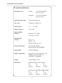
B. System Specifications
Operating Power:
Camera
115 VAC 50/60 HZ or
220 VAC 50/60
Laminator
115 VAC 50/60 HZ or
220 VAC 50/60
Strobe Recharge Time:
10 Seconds, Maximum
Face Lens:
4 Element, 114 MM, f4.5
Shutter Speed:
7.8
Shutter Apertures:
f4.5/ to f45
Camera-Subject
Distance:
DC Operating
Voltages:
+ 2.7 msec.
Standard - 54" (1.4M)
Close-up - 40" (1M)
Logic - 5.0
Strobes - 330
Motor & Solenoids - 16.0
Polaroid Film Types:
661, 664, 668, T669P,
POLACOLOR, POLAHYBRID
Camera Back:
CB 103 Filmholder
Safety Certifications:
Meets UL-122, CSA-C22.2 NO, 118,
VDE/IEC 380 FCC PARTS 15,
ANSI PH3.710 Standards
Weight:
Actual Weight: 45 lbs.
Dimensions:
Operating Mode (vertical camera)
H
W
D
31.5"
23"
11.25"
80.01cm
58.42cm
28.58cm
Carrying Case with Base (handle folded)
H
W
D
17.75"
23"
11.25"
45.09cm
58.42cm
28.58cm
1-5
[This page intentionally blank]
Polaroid ID-4 Service Manual
SECTION 2
SYSTEM COMPONENTS &
THEORY OF OPERATION
2-1
Polaroid ID-4 Service Manual
2-2
Polaroid ID-4 Service Manual
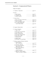
Section 2 - Components & Theory
Table of Contents
A. Sequence of Operation
........................... page 2-5
B. Optics
1. Data Exposure
2. Validation Plate
3. Portrait Exposure
........................... page 2-7
........................... page 2-11
........................... page 2-13
C. System Power
1. Base Unit Wiring Connections ........................... page
2. DC Power Supply
........................... page
3. Film Development Timers
........................... page
4. DC Voltage Distribution
in the Camera Head
........................... page
2-19
2-19
2-21
2-21
D. Operator Display Panel
........................... page 2-23
E. Camera Electronics
1. Logic Circuit
2. Photo Sensors & PC Board
3. Face Strobe Circuit
4. Motor Control Board
5. Face Strobe Trigger Board
6. Data Strobe Circuit
7. Ranging Module
8. Display Board
9. DIP Switch S2 on Logic Board
........................... page 2-27
........................... page 2-33
........................... page 2-35
........................... page 2-37
........................... page 2-37
........................... page 2-39
........................... page 2-41
........................... page 2-43
........................... page 2-45
F. Software Control of System Operation
1. Control Program Basic Description
........................... page 2-47
2. "Interrupt" Functions
........................... page 2-49
3. Logic Section Functions
During Power Up
........................... page 2-51
4. Logic Section Functions
During Data &
Portrait Exposures
........................... page 2-53
5. Diagnostic Testing Program
Using An External Computer ........................... page 2-55
2-3
Polaroid ID-4 Service Manual
Notes
2-4
Polaroid ID-4 Service Manual
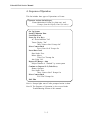
A. Sequence of Operation
This list includes three types of Operations or Events:
Operator Actions (in bold type),
Electro-Mechanical Events (in plain text), and
Prompts from the Display Panel (in italics)
Set Up System
Install Validation Plate
Load Film Pack
Power Up (Use Key)
AC Power Indicator "On"
Timers Display "On"
"Move Camera Back Prompt On"
Move Camera Back
"Insert Data Card" Prompt On
Insert Data Card
Data Strobe Fires
Mirror Moves
"Take Face" Prompt On
Aim Light "On"
Depress S1 (Range - Aim)
Subject Distance is "checked" by sonar-system
Continue to Depress S1-2 (Take Face)
Shutter Operates
Face Strobe Fires
"Move Camera Back" Prompt On
Move Camera Back
"Pull Film" Prompt On
Pull Film
Note A: Prompt lights turn off after prompted action is taken.
Note B: The Sequence of Operation is also covered in the
Troubleshooting Section of this manual.
2-5
Polaroid ID-4 Service Manual
Motor-Driven
Mirror
(Camera
Back)
Film
Fixed
Mirror
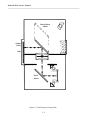
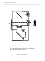
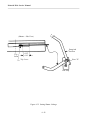
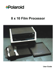
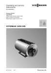
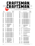
Figure 2-1 Data Exposure Image Path
2-6
Polaroid ID-4 Service Manual
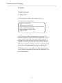
B. Optics
1. Data Exposure
1a. Image Path
The Data Exposure Image Path is shown in Fig. 2-1.
The Light from the Data Strobes:
• Strikes the Data Card
• Reflects onto Fixed Mirror
• Passes through Fixed Aperture, Lens & Polarizer
• Strikes Motor-Driven Mirror
• Passes through Validation Plate
• Exposes Film
The Motor-Driven Mirror is mounted on a carriage driven
either up or down by a small DC motor and gear train. Logic
Circuit signals energize the motor and control rotational
direction to move the mirror up and down. Before Data Card
exposure, the motor drives the mirror into the lower position.
Before Face exposure, the mirror is driven to its upper position
to provide a clear path between the face lens and the film.
If the Data Exposure is too light or too dark, a potentiometer
on the Operator Control Panel allows for the adjustment of the
Data Strobe duration.
2-7
Polaroid ID-4 Service Manual
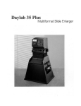
Data
Card
Data Card
Sensor
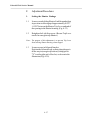
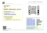
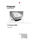
Figure 2-2 Data Card Holder
2-8
Polaroid ID-4 Service Manual
1b. Data Card Sensing
The Data Card Holder is shown in Fig. 2-2.
When an ID badge is to be made, a Data Card is prepared and
inserted in the slotted Data Card Holder at the right front of
the Camera. Presence of the Data Card in the Holder is sensed
by an opto-interrupter in the Camera, which supplies the logic
signal input necessary to turn on the Aim Light and fire the
Data Strobe flashtubes.
2-9
Polaroid ID-4 Service Manual
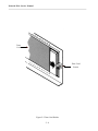
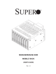
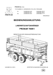
Note: Be sure to insert Validation Plate in the direction shown above.
Figure 2-3 Validation Plate
2 - 10
Polaroid ID-4 Service Manual
2. Validation Plate
The Validation Plate is a Polarized plastic plate which is
installed in the Camera Back by the operator.
Validation Plate Functions:
• To enable the exposure of the validating seal, signature
or other security element onto the ID card
• To enable the exposure of the Portrait and Data on
distinct and separate areas on the film
The "masking" by the Validation Plate is accomplished by
polarizing its Data area surface in one plane, and its Face area
surface in a different plane (see Fig. 2-3). When the Data
exposure is made, a polarizing filter in the Data image path
polarizes the light rays in the same plane as the polarized Data
area on the Validation Plate. Thus the Data image light can pass
through only the Data area of the Validation Plate, leaving the
Face area unexposed and ready for the subsequent Face
exposure. The same process occurs during Face exposure: the
polarizer behind the Face Lens corresponds to the Validation
Plate Face Area polarizer, permitting the face image to expose
only the face area of the film.
The Validation Plate is in direct contact with the film during
Data and Face exposures, and is lifted away to prevent
scratching during movement of the Camera Back. A logic
controlled solenoid moves the Plate into the film plane before
the Data and Face Strobes fire, and away from the film after
each exposure.
2 - 11
Polaroid ID-4 Service Manual
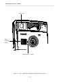
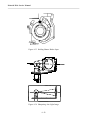
Aim Light
Sonar
Ranging
Guide
Lighten/Darker Control
Figure 2-4 Aim Light/Sonar Rangefinder/Lighten-Darken Control
2 - 12
Polaroid ID-4 Service Manual
3. Portrait (Face) Exposure
3a. Aim Light
The Aim Light is shown in Fig. 2-4.
Aim Light Features:
• Used to center the face image in the portrait area (should
be aimed at subject's upper lip)
• Consists of a customer replaceable 16V bulb and lens
assembly
• Emits a spot, one inch in diameter
• Shines for 10 seconds after Data Strobes have fired
• May be re-lit by partially depressing the shutter release
3b. Sonar Rangefinder
The Sonar Rangefinder is shown in Fig. 2-4.
Sonar Ranging Guide Features:
• Assists the operator in positioning the subject at the correct
distance from the Camera (see System Specifications for
correct distance)
• Activated (with Aim Light) by partial depression of
shutter release
• Does not inhibit Camera function
To signal the operator that the system is ready for the subject
exposure, a green LED lights below the symbol for Shutter
Button operation on the Control Panel.
2 - 13
Polaroid ID-4 Service Manual
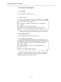
Face Brightener
Figure 2-5 Display LED and Face Brightener (Two-Up Camera)
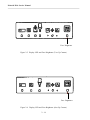
Face Brightener
Figure 2-6 Display LED and Face Brightener (One-Up Camera)
2 - 14
Polaroid ID-4 Service Manual
3c. Face Exposure Adjustment
Two Camera Head controls are provided to achieve the best
face exposure on the completed ID card. If the subject's image
is too dark, a Face Brightener increases the facial illumination
by one-half an f/stop. Pushing the face brightener symbol at
the right end of the Control Panel (a soft key) activates the
Face Brightener for the next exposure only (see Figs. 2-5, 2-6).
In addition, the Camera Head also has a Lighten/Darken
control which will increase or decrease the shutter aperture by
one-half an f/stop per detent. The aperture is adjusted by
turning the lens bezel, either toward the "❍" to lighten the
exposure, or toward the "●" to darken. See Fig. 2-4.
2 - 15
Polaroid ID-4 Service Manual
(C)
(D)
(B)
(A)
(B)
(C)
(D)
Reflects from the Subject
Passes through the lens and polarizer
Passes through the polarized face area on the Validation Plate
Exposes the portrait area of the film
Figure 2-7 Face Image Path
2 - 16
(A)
Polaroid ID-4 Service Manual
3d. Image Path
When the two-stage shutter button is fully depressed, the face
strobe fires and the face exposure is made. The shutter system
is mechanically interlocked so that it is fully open when the
face strobe circuit is energized.
Face Optical System consists of:
•
•
•
•
Variable-aperture shutter
Four-element lens system
Image polarizing filter
Validation Plate
The Face Image Path is shown in Fig. 2-7.
The Light emitted by the Face Strobe:
• Reflects from the Subject
• Passes through the lens and polarizer
• Passes through the polarized face area on the Validation
Plate
• Exposes the portrait area of the film
Note: The motor-driven mirror which was in the "down"
position for the Data exposure has now been moved up
by a logic circuit control signal, to provide a clear path
between the face lens and film in the Camera Back.
2 - 17
Polaroid ID-4 Service Manual
Notes
2 - 18
Polaroid ID-4 Service Manual
C. System Power
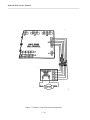
1. Base Unit Wiring Connections
AC line voltage (115 VAC @ 60 Hz or 225 VAC @ 50 Hz) enters the
ID-4 Base through Filter FL1 and keylock Switch S1, as shown in the Base
Unit Wiring Diagram, Schematic A-1 (see Appendix). The line voltage
supplies the AC Power ON indicator, the Power Supply through P1-J1, and
the Laminator through J4. Overload protection of the Power Supply and
Laminator is provided by circuit breakers CB-1 and CB-2.
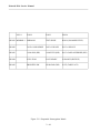
2. DC Power Supply
The Power Supply for the ID-4 System is located in the Base Unit.
The Base Unit Wiring Diagram is shown in Schematic A-2(1)
(see Appendix).
There are two AC-DC transformers (T1 & T2) which supply DC power to
the System. The Base Unit Power supply also includes an AC out for the
Laminator. The four DC currents are described in the following table.
Current
From
To
For
8 VDC
Unregulated
T1
Camera
Connector
Camera
Logic
5 VDC
Regulated
T1
Film Developing
Timers*
16 VDC
Unregulated
T2
Camera
Connector
Face & Data
Strobe Capacitors
16 VDC
Constant Current
T2
Camera
Connector
Aim Light
* Back-up batteries are provided to preserve pre-set Timer values
during power down periods.
2 - 19
Polaroid ID-4 Service Manual
Notes
2 - 20
Polaroid ID-4 Service Manual
3. Film Development Timers
Two electronic LCD Timers are mounted on the Base Unit for
convenience in timing the development of two prints. They
operate on 5 VDC from the Power Supply and contain back-up
batteries to preserve memory if AC power fails. Depressing a
button on the Timer starts the countdown; an audible beep
signals its completion. Timing interval is adjustable to
accommodate different Polaroid films.
4. DC Voltage Distribution in the Camera Head
As shown in Schematic A-3 (see Appendix), the Power Supply
DC voltages at the Camera Connector are fed first to the Face
Strobe PC Board in the Camera Head. From the Face Strobe
PC Board, the required DC voltages are next sent to the Data
Strobe Timing and Logic Boards.
The Logic Board, in turn, supplies the voltages required by the
Display LEDs; distance-measuring Sonar; solenoids for the
Shutter, Validation Plate, and Face Brightener aperture;
Camera Back and Data Card position sensors; the mirror Drive
Motor; and the Camera exposure Counter.
2 - 21
Polaroid ID-4 Service Manual
Notes
2 - 22
Polaroid ID-4 Service Manual
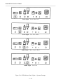
D. Operator LEDDisplay/Control Panel
The Operator Control Panel LEDs and their functions are
shown on the following two pages. The four LEDs on the
left-hand page (Fig. 2-8a) are operator prompts, and the action
indicated must be taken before Camera operation can continue. The four on the right-hand page (Fig. 2-8b) do not
inhibit Camera operation.
Note: The Operator Control Panels shown are for a Horizontal
Two-up camera. Yours may differ slightly.
The LEDs also function as signals of System errors requiring
power down and/or servicing. The first and last LEDs
alternately flash and a combination of the other LEDs
illuminates. These codes and conditions are described in the
Operator Panel Error Display Codes in the Diagnostics &
Troubleshooting section of this manual.
2 - 23
Polaroid ID-4 Service Manual
Green Light – Insert Data Card
Green Light – Fire Face Strobe
Amber Light – Move Camera Back
Amber Light – Pull Film
Figure 2-8a LED Indicator Panel Lights – Operator Prompts
2 - 24
Polaroid ID-4 Service Manual
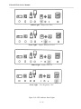
Amber Light – Subject Too Close
Green Light – Subject Distance Correct
Amber Light – Subject Too Far
Green Light – Face Brightener "On"
Figure 2-8b LED Indicator Panel Lights
2 - 25
Polaroid ID-4 Service Manual
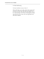
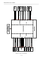
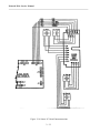
Figure 2-9 Logic Circuit Blocks
2 - 26
Polaroid ID-4 Service Manual
E. Camera Electronics
1. Logic Circuit
The Logic Block Diagram (Fig 2-9) shows the Inputs and
Outputs of the Logic Circuit. Microcomputer U1 is the heart
of the Logic Circuit, coordinating and controlling all events in
the camera cycle through resident software. (See "F. Software
Control of System Operation.") Additional information on the
function of U1 is provided in The Program Flowchart
(Schematic A-4) and the Timing Chart (Schematic A-5) in the
Appendix.
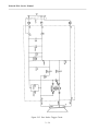
The clock pulse required for the timing functions performed
by U1 is supplied by Crystal Oscillator Y1 (Fig. 2-10). Reset at
power up is provided by R19 and C1. When Vcc is first
applied to the Logic Circuit, C1 is in a discharged state and 5V
is applied to pin 9 (RST), placing all outputs in an OFF state.
C1 is charged through R19 to make pin 9 low and permit
operation of the IC. (See Logic Board schematic [A-6] in the
Appendix.)
The Logic Board has its own 5V regulator (U12) for Vcc,
which also supplies 5 VDC to the Display and Sensor PC
Boards (see Fig. 2-11).
2 - 27
Polaroid ID-4 Service Manual
Figure 2-10 Microcomputer Power Input, Computer Interface and Clock Input
2 - 28
Polaroid ID-4 Service Manual
Figure 2-11 Logic Board 5 VDC Regulator Circuit
2 - 29
Polaroid ID-4 Service Manual
Figure 2-12 Logic Circuit Inputs
Figure 2-13 Logic Circuit Outputs
2 - 30
Polaroid ID-4 Service Manual
Inputs to the Logic Circuit (Fig. 2-12) include:
• Logic Inputs high or low
• Closed Circuit Loops
ex. Face Brightener (J3-4,-8) & Pull Film (J3-7, J12-10)
• Shutter Synchronization Signal (through J7)
Outputs from the Logic Circuit (Fig. 2-13) include:
• Buffered Signals
ex. Too Close (J12-5), Too Near (J12-3),
Move Camera Back (J12-1)
• Unbuffered Signals
ex. Motor Drive Controls:
MOT-ENAB, MOT-DIRECT, MOT-BRK
• Current Limiting
[Shutter Solenoid (J7-4,J7-1)]
2 - 31
Polaroid ID-4 Service Manual
Figure 2-14 Sensor PC Board Interconnections
2 - 32
Polaroid ID-4 Service Manual
2. Photo Sensors & Sensor PC Board
Four Photo Sensors are used in the ID-4 to sense the positions
of the Mirror and the Camera Back (see Fig. 2-14).
2a. Mirror Position Sensors
U3 MIR 1 and U4 MIR 2 are the Mirror Position Sensors. As
the motor drives the Mirror carriage from one position to
another, tabs on the carriage intercept the cavities of U3 and
U4. The Logic Circuit control program uses these position
signals to ensure that the Mirror is in the correct position when
the Data Card and Face exposures are to be made, and to
measure Mirror Move Time.
Mirror Position
(Sensor Output)
U3
U4
Down (Data Position)
Up (Face Position)
In Between
High
Low
Low
High
Low
High
2b. Camera Back Position Photo Sensors
U1 CAM DN and U1 CAM UP are the Photo Sensors for the
Camera Back position. When the operator slides the Camera
Back from one position to another after taking a picture, a tab
on the Back moves out of the cavity of one sensor and into the
cavity of another. The resulting sensor outputs are fed through
the Sensor Board to the DIP Switch S2-3 and S2-4, analog
switch U7 and Microcomputer U1 on the Logic Board.
2c. Sensor PC Board
The Sensor PC Board is essentially an interconnecting board
between the Sensors and the Logic Board. As shown in
Schematic A-7 (see Appendix), the circuit includes four currentlimiting resistors, R1-R4 for the LED portions of the photo
sensors.
2 - 33
Polaroid ID-4 Service Manual
Figure 2-15 Face Strobe Trigger Circuit
2 - 34
Polaroid ID-4 Service Manual
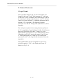
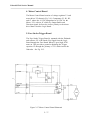
3. Face Strobe Circuit
The Face Strobe circuit is shown in Fig. 2-15.
Face Strobe Circuit Features:
• 16VDC unregulated is converted up to 330VDC for the
Face and Data photoflash capacitors via oscillator Q1-Q4
and diodes D1-D4 and step-up transformer T1.
• Regulation of 330VDC is controlled by ZD2 & ZD3
which turn on Q7 to inhibit charging.
• Face Ready signal is controlled by ZD1 turning on Q6.
• U1 regulates the 8VDC to 5VDC for K1 relay.
• K1 relay closes, when de-energized. This discharges the
Face photoflash capacitors (C1 & C2) and the Data photo
flash capacitors (C5 & C7 on the Data timing board),
through R8 & R17.
• When Q5 is turned on*, the oscillator is inhibited from
charging.
*Q5 turns on when:
• Face, Data 1, & Data 2 ready signals received at the logic
board microcomputer send a high signal (E7) through D9
or
• Face Trigger signal is sent through D11 or
• K1 stays closed and activates D13
2 - 35
Polaroid ID-4 Service Manual
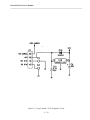
Figure 2-16 Motor Control Board Interconnections
2 - 36
Polaroid ID-4 Service Manual
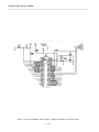
4. Motor Control Board
The Motor Control Board consists of voltage regulator U1 and
motor driver U2 shown in Fig. 2-16. Components U1, R1, R2,
and C1 reduce the 16 VDC unregulated to 10 VDC for the
Motor. U2 is a driver IC which, by Output Enable and
Direction signals, delivers the correct polarity to the mirror
drive Motor from the Logic Board.
5. Face Strobe Trigger Board
The Face Strobe Trigger Board is mounted with the Flashtube
and reflector. E2 is the Strobe Fire Signal from the Logic
Board through the Face Board. When E2 goes high, SCR1
turns on. This provides a ground to discharge the Trigger
capacitor C2 through the primary of TC1 which ionizes the
flash tube. See Fig. 2-15.
P10
Figure 2-17 Motor Control Board Schematic
2 - 37
Polaroid ID-4 Service Manual
Notes
2 - 38
Polaroid ID-4 Service Manual
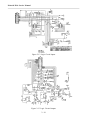
6. Data Strobe Circuit
The Data Strobe Circuit includes the Quench Board and the Timing
Board, which are shown in Schematic A-8 (see Appendix).
The Quench Board contains:
1. The trigger circuits for the Data Flashtubes
• trigger capacitors C3 & C5
• trigger coils TC1 & TC2
• SCR2 common to ground C3 & C5
2. The Quench Circuit
• the high signal fr om E13 through DTH1 (o ptoisolator) which grounds the 330V through choke L1
The Timing Board contains:
1. Data Photoflash capacitors C7 & C8
2. Data 1 & Data 2 ready circuits
• ZD1 & Q10 for Data 1 ready
• ZD2 & Q9 for Data 2 ready
3. Quench signal time constant adjustment and signal
(VR1, Q5, Q6 & Q1)
4. The data fire pulse (Q2, Q3, Q7 & Q8)
2 - 39
Polaroid ID-4 Service Manual
Notes
2 - 40
Polaroid ID-4 Service Manual
7. Ranging Module
The Ranging Module schematic is shown in Schematic A-9
(see Appendix).
This Module provides the ultra-sonic pulse transmission and
echo reception from which the Logic Board computes
Camera-to-Subject distance. The primary components of the
Ranging Circuit are ICs U1 and U2, power transistor Q1,
output transformer T1 and the Transducer.
The Module is powered through J2-1 (Range Enable on the
Logic Board). Transmission begins when J2-3 (XMIT-BEGIN)
goes high. The Ranging Module Transducer transmits an
ultrasound burst of 1 µsec, then waits for an echo.
The echo is detected through pin 1 U1 on the Ranging Module.
This causes pin 9 of U2 to go high, and in turn, pin 2 (RLOG)
of J2 on the Logic Board. Microcomputer U1 on the Logic
Board then measures the elapsed time between transmission
and reception, and calculates Camera-to-subject distance from
the time.
2 - 41
Polaroid ID-4 Service Manual
Figure 2-18 Display Board Circuit
2 - 42
Polaroid ID-4 Service Manual
8. Display Board
The Display Board is shown in Fig. 2-18.
Display Board Functions:
• Provides System status displays for the operator
• Controls the Face Brightener Switch & its indicating LED
• Provides feed-through connections to the Logic Board for
the camera back counter & switch S1*
* S1 is a soft-switch at the end of the panel, which when
closed lights the Face Brightener LED (8) and actuates the
Face Brightener Solenoid through Logic Board Circuitry, for
the next exposure only.
Signal/operating voltage lines between the Logic Board and
the S1 Button (Ranging and Fire Face Strobe), Pull Film
microswitch and Validation Plate solenoid on the Camera
Back, and the Counter, are also made through connections on
the Display Board.
2 - 43
Polaroid ID-4 Service Manual
Notes
2 - 44
Polaroid ID-4 Service Manual
9. DIP Switch S2 on Logic Board
Position
Position
Position
Position
1:
2:
3:
4:
Data Card Override
Camera-Subject Distance
Moveable Back 1
Moveable Back 2
The four Positions on DIP Switch S2 should be set as follows:
Position 1 OFF:
Position 1 ON:
Position 2 OFF:
Position 2 ON:
Data Exposur e occur s only after
inser ting Data Card.
Camera makes second Data Exposure
without removing and replacing Data
Card. Second exposure occurs after
moving the Camera Head down. (Used
when two IDs of same subject are
needed.)
Standard Lens in use. Camera 54" from
subject.
Close-Up Lens ( #663 ) in use. Camera
40" from subject.
Positions 3 & 4 must be set together.
Position 3&4 OFF: Camera has Fixed Back.
Position 3&4 ON: Camera has Moveable Back.
2 - 45
Polaroid ID-4 Service Manual
Notes
2 - 46
Polaroid ID-4 Service Manual
F. Software Control of System Operation
1. Control Program - Basic Operation
A software program resident in the Logic Board's
microcomputer primarily serves two purposes in the ID-4
system:
(a) Helps automate the process of producing ID badges, by
making a software program responsible for timing and
monitoring the overall flow of picture-taking steps;
(b) Enhances the ID-4's productivity by assuring circuit
readiness and providing operator prompts throughout the
operating sequence.
Below are brief explanations of what the two main sections of
the program do. The sequence of these functions can also be
visualized by referring to the Program Flowchart (Schematic A-4)
and the Timing Chart (Schematic A-5) in the Appendix.
In addition, a third part of the ID-4 software permits diagnostic
testing of individual Camera functions, using an external
computer. This capability is described at the end of this
section.
2 - 47
Polaroid ID-4 Service Manual
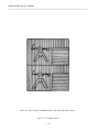
POLL1
POLL2
POLL3
POLL4
READ1 MIRROR 1
MIRROR 2
TEST SENSE
RLOG (SONAR RECEIVE)
READ2
DATA CARD SENSE
DATA 2 READY
DATA 1 READY
READ3
CAM ODD (DIP)
CAM EVEN (DIP)
DATA CARD OVERRIDE (DIP)
READ4
PULL FILM
FACE READY
S1 RANGE (PREVUE)
READ5
BRIGHTEN SW
NEAR/FAR (DIP)
S1 FF (TAKE FACE)
Figure 2-19 Sequential Interrogation Matrix
2 - 48
Polaroid ID-4 Service Manual
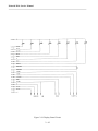
2. "Interrupt" Functions
This portion of the software controls the basic timing, reads
and stores microcomputer inputs, and monitors or controls
critical events in the Camera cycle.
"Interrupts" are generated once every millisecond (every 250
µsec during sonar distance ranging) by an internal timer in
microcomputer U1. A software timer determines the timing of
all solenoid actuation, strobe fire, ranging, strobe recharging,
etc.
This section of the control program also continuously tracks of
"polls" 16 conditions in the Camera Head every millisecond.
This assures that the Logic Section of the software will always
be using up-to-date information as it controls the overall flow
of operations.
The matrix (Fig. 2-19) depicts these sequential interrogations
of the group of inputs READ1 through READ5. At POLL1,
the states of all five inputs (READ1 through READ5) are
instantaneously sensed and stored, in BCD form, in four
registers of microcomputer U1. (At POLL1, only Mirror
position 1 is looked at.) One-quarter millisecond later, at
POLL2, five inputs are again sensed and stored. The process
is repeated at POLL3 and again at POLL4, at which time the
series of four interrogations begin again. The process might
be visualized as four snapshots (POLLs) in rapid sequence,
with each snapshot recording the states of five variables
(READs).
In addition to the states and events shown in the matrix, the
microcomputer also monitors and controls the Aim Light 10sec. timeout, the Mirror 2-sec. timeout, and the 15-sec. Strobe
Ready timeout.
2 - 49
Polaroid ID-4 Service Manual
Notes
2 - 50
Polaroid ID-4 Service Manual
3. Logic Section Functions During Power Up
The control program first places all outputs of the
microcomputer in an OFF state, sets the internal timers and
enables the interrupts. Flags are set to initial conditions and
power supplies are allowed 250 msec. to stabilize. The
Converter Inhibit Line is turned off, allowing the 16 VDC to
330 VDC Converter to charge the Date and Face Strobe
capacitors.
The program next checks the Test-Sense input (U8, pin 13) on
the Logic Board (see READ1, POLL3 in the preceding
matrix). If the input is ON, the regular ID card program
continues. But if the input is switched OFF, the "Test"
functions are active and the program then jumps to the
"TestRoutines" sub-program. This diagnostic facility is
described at the end of this section.
The Face Strobe and Data Strobes are then checked for full
charge with a 15-second timeout. The Mirror motor drive is
energized to place the Mirror in its lower Data Card exposure
position.
And finally, the four sections of the factory-set DIP Switch S2
on the Logic Board are checked, so the remaining control
program will know:
-
whether automatic second Data Card exposures should
be made - S2-1 ("Data Card Override" - see READ3,
POLL4 in matrix);
-
whether near-focus or far-focus lens is in use - S2-2;
-
whether the Camera Back is moveable or fixed - S2-3,4.
2 - 51
Polaroid ID-4 Service Manual
Notes
2 - 52
Polaroid ID-4 Service Manual
4. Logic Section Functions During Data &
Portrait Exposure
The control program now progresses through all steps
necessary to produce two ID cards on a single sheet of film,
including prompting the operator and waiting when a manual
operation must be performed. The sequence of these steps and
LED displays (prompts or system errors) is most easily
understood by looking at the flowchart, Schematic A-4 (see
Appendix), which shows the steps necessary to produce one ID
card or badge. In a two-up system (two cards per film sheet),
the entire Data Card-Face Exposure process is repeated, after
moving the Camera Back either up or down. The internal
counter in microcomputer U1 then increments to "2" ("Cam
Even" input on the Timing Chart), causing the PULL FILM
LED to light.
The time-relationship of the events to each other is visually
depicted in the Timing Chart, Schematic A-5 (see Appendix).
(Bear in mind that most Camera Head devices are low
activated – that is, solenoid and LEDs are activated when
outputs go low rather than high.)
2 - 53
Polaroid ID-4 Service Manual
Notes
2 - 54
Polaroid ID-4 Service Manual
5. Diagnostic Testing Program Using An External
Computer
The ID-4 system software also includes a "TestRoutines"
program for use with an external computer (PC, laptop, etc.).
This permits activating individual components such as the
Shutter, Aim Light, Face Strobe, etc. by keystroke, and
monitoring the status of the sensors such as Strobe Ready,
Camera Back position, etc.
To send commands and receive information from the
computer, Test-Sense input J9 pin 3 must be grounded,
causing U8-1 and U8-2 to switch to OFF. This instructs U1's
program to jump to the test mode ("TestRoutines"), enabling
TXD and RXD through J9-4 and J9-5 connected to the
external computer. This diagnostic exercise feature with an
external computer gives maximum testing flexibility of
Camera functions.
2 - 55
[This page intentionally blank]
Polaroid ID-4 Service Manual
SECTION 3
DIAGNOSTICS & TROUBLESHOOTING
3-1
Polaroid ID-4 Service Manual
3-2
Polaroid ID-4 Service Manual
Section 3 - Diagnostics & Troubleshooting
Table of Contents
A. Operator Panel Error Display Codes
................. page 3-5
B. Test Program Using External Computer
................. page 3-7
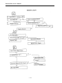
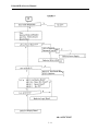
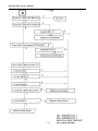
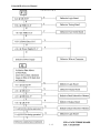
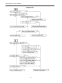
C. Troubleshooting Charts
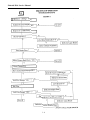
1. Sequence of Operation - Chart A
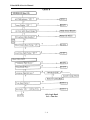
2. Sequence of Operation - Chart B
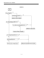
3. Charts C,D,E
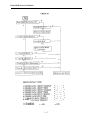
4. Chart F
5. Chart F1
6. Chart F2 & G
7. Charts H & I
8. Charts J & K
9. Chart L
10. Chart M
................. page 3-8
................. page 3-9
................. page 3-10
................. page 3-11
................. page 3-12
................. page 3-13
................. page 3-14
................. page 3-15
................. page 3-16
................. page 3-17
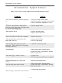
D. Common Errors – Symptom & Analysis
................. page 3-18
3-3
Polaroid ID-4 Service Manual
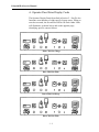
Face Did Not Charge
Face Did Not Flash
Mirror To Data Timeout
Mirror To Face Timeout
3-4
Polaroid ID-4 Service Manual
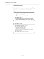
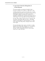
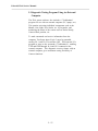
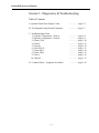
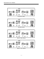
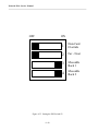
A. Operator Panel Error Display Codes
The Operator Display Panel (described in Section 2 – Part D) also
functions as an indicator of eight specific System errors. When an
error has occurred, the first and last LEDs will flash. Other LEDs
will illuminate, as shown below and on the opposite page,
identifying specific camera failures.
Data 1 Did Not Charge
Data 1 Did Not Flash
Data 2 Did Not Charge
Data 1 Did Not Flash
3-5
Polaroid ID-4 Service Manual
Notes
3-6
Polaroid ID-4 Service Manual
B. Test Program Using External Computer
The ID-4 System includes a "TestRoutines" program for use
with an external IBM compatible computer (PC, Laptop, etc.).
This permits activating individual components such as the
Shutter, Aim Light, Face Strobe, etc. by keystroke, and
monitoring the status of the sensors such as Strobe Ready,
Camera Back position, etc.
Connection of the computer to the camera is through the J9
connector on the Logic Board. The cable (P/N 13387) needed
for this purpose is available from Material Services. The driver
for "TestRoutines" is also available from Material Services
(5&1/4" floppy - P/N 13399)
For further assistance, call Polaroid Technical Assistance:
(800) 225-1618.
3-7
Polaroid ID-4 Service Manual
3-8
Polaroid ID-4 Service Manual
3-9
Polaroid ID-4 Service Manual
3 - 10
Polaroid ID-4 Service Manual
3 - 11
Polaroid ID-4 Service Manual
3 - 12
Polaroid ID-4 Service Manual
3 - 13
Polaroid ID-4 Service Manual
3 - 14
Polaroid ID-4 Service Manual
3 - 15
Polaroid ID-4 Service Manual
3 - 16
Polaroid ID-4 Service Manual
3 - 17
Polaroid ID-4 Service Manual
D. Common Errors – Symptom & Analysis
Note: Always check for repair updates before performing alternative repairs.
Symptom
Analysis
• After first face flash the "pull film" light goes
on.
• Check for voltage doubler update.
• Replace photosensor assembly (Camera Back).
• Check Camera Back Alignment (Two-Up)
• When face trigger button is depressed the
mirror moves and "insert data card" light comes
on. (No face fire/ranging light.)
• Replace ranging board.
• Data exposure uneven.
• Replace data strobe tubes.
• Replace data/timing board.
• Error code flashes after first data is triggered.
• Replace logic board.
• Data not firing after card inserted. (Face
trigger light comes on.)
• Wrong version E-Prom.
• Defective logic board.
• Data not firing after camera is moved to
position #2. ("Move film back" or "insert data
card" light comes on.)
• "Pull film" switch dirty/closed.
• No data trigger.
• Data card too narrow (missing sensor).
• Photo sensor dirty or dislocated by inserting
holder in upside-down.
• False data trigger. (Double exposure.)
• Operator error.
• RF radio frequency interference (see update).
• Delayed during power up. (Error code
flashes.)
• Replace power supply board.
• Data card too narrow (missing sensor).
• Photo sensor dirty or dislocated by inserting
holder upside-down.
• Data not firing when card is inserted.
• Camera Back out of position.
• Data not firing. ("Insert data card" and "move
3 - 18
Polaroid ID-4 Service Manual
back" light comes on.)
Analysis
Symptom
• Replace data/timing board.
• Intermittent black data. (Logic ignores
problem.)
• Operator error.
• RF radio frequency interference (see update).
• Check for miswire on data/timing board.
• Replace data/timing board.
• Data overexposed. (False triggering occurs
when unit is turned off or while in operation.)
Replace optosensor board in Camera Back.
• Delayed data fire (error code flashes) – very
intermittent.
• Shutter linkage/solenoid sticking in closed
position. Replace solenoid.
• No face strobe or shutter release when face
button is pressed. (Error code flashes.)
• Check shutter sync contacts.
• Replace shutter.
• No face strobe fire (shutter operates but not
counter advance). (Error code flashes.)
• Replace ranging board.
• No face strobe fire. (When button is depressed
the mirror moves and "insert data card" light
comes on.) (No face fire/ranging light.)
• Replace power supply board.
• Delayed during power up. (Error code flashes.)
• Check for (U2) update on power supply board.
• Replace logic board.
• Point light flickers/inoperable.
• Replace display board.
• Unit not ranging/no point lamp when face
trigger button is depressed. (All other functions
work during this malfunction.)
• Replace data/timing board.
• Intermittent black data. (Logic ignores
problem.)
• Turning power switch to "off" position causes
data strobe to fire. Result: data washout.
• Check for miswire at TC1, TC2, E1, E2, E3, or
E4 on timing board.
• Replace data/timing board.
3 - 19
[This page intentionally blank]
Polaroid ID-4 Service Manual
SECTION 4
DISASSEMBLY, ADJUSTMENTS &
WIRING
4-1
Polaroid ID-4 Service Manual
4-2
Polaroid ID-4 Service Manual
Section 4 - Disassembly, Adjustments & Wiring
Table of Contents
A. Service Access Parts Finder
........................... page 4-5
B. Cautions, Reminders & Tools
........................... page 4-9
C. Level 1 Parts Removal
........................... page 4-13
D. Level 2 Parts Removal
........................... page 4-31
E. Level 3 Parts Removal
........................... page 4-53
F. Adjustment Procedures
1. Setting the Shutter Linkage
2. Setting the Aim Light
3. Setting the DIP Switch S2
4. Focusing the Face Lens
5. Replacing the Face Polarizer
........................... page 4-57
........................... page 4-59
........................... page 4-61
........................... page 4-63
........................... page 4-65
G. Camera Wire Routing
1. Face Strobe Board, Shutter,
Face Brightener, Transducer Wiring
2. Data Flashtube & Face Strobe
Board Wiring
3. Wiring Between Quench, Timing,
Face Strobe & Logic Boards
4. Ribbon Cable Connecting Camera
Back & J2 Display Board
4-3
.......................... page 4-66
.......................... page 4-67
.......................... page 4-68
.......................... page 4-69
Polaroid ID-4 Service Manual
Notes
4-4
Polaroid ID-4 Service Manual
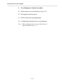
A.
Service Access Parts Finder
In this manual and in the accompanying videotape, the main
components of the ID-4 are grouped in three levels as follows:
Level 1 - Parts or Assemblies which may be accessed after the
removal of the Front Cover.
Level 2 - Parts or Assemblies which require the removal of
both the Front and Back Covers.
Level 3 - Parts or Assemblies which require the removal of
both Covers and the separation of the Main Frame from the
Baseblock.
Each of the 30 primary ID-4 Parts and Assemblies
are listed on page 4-7 along with its Level
and page reference for this manual.
4-5
Polaroid ID-4 Service Manual
Notes
4-6
Polaroid ID-4 Service Manual
Part or Assembly
Level
Page
____________________________________________________
Aim Light Assembly
1
4-21
Back Cover
1
4-19
Back Plate Assembly
2
4-33
Base Slide Spacer Assembly
2
4-35
Camera Back Assembly
*
Camera Back Stop
2
4-35
Counter
2
4-31
Data Card Sensor Cable Assembly
1
4-29
Data Flashtubes
3
4-53
Data Strobe Board
2
4-39
Display Board
2
4-33
Face Brightener Solenoid Assembly
1
4-25
Face Polarizer
*
Face Strobe Board
2
4-39
Face Strobe Reflector Assembly
1
4-21
Flash Channels
3
4-55
Front Window (top of front cover)
1
4-17
Horizontal Reflectors
3
4-55
Latch Mechanism
2
4-35
Logic Board
2
4-37
Lower Mirror
2
4-45
Mirror Carrier
2
4-43
Parallel Reflectors
3
4-55
Photo Sensors
2
4-47
S1 Switch Assembly
2
4-33
Shutter Assembly
2
4-51
Shutter Solenoid Assembly
1
4-29
Transducer & Ranging Board
1
4-27
Upper Mirror
2
4-41
Validation Plate Solenoid
2
4-35
* These items may accessed directly.
4-7
Polaroid ID-4 Service Manual
Notes
4-8
Polaroid ID-4 Service Manual
B.
Cautions, Reminders & Tools
1.
Cautions & Reminders
1.1.
Check Strobe capacitors with VOM for
presence of DC voltage, before working on
Boards.
1.2.
Do not fire Data Strobes with flashtubes
disconnected — this candamage circuit.
1.3.
Do not touch glass surface of flashtubes
with fingers.
1.4.
When installing the front cover, hold Aim
Light Blinders apart with fingers or
soldering aid to prevent scratching Aim
Light Lens.
1.5.
Do not pull on wires to disconnect cables:
lift connectors off board.
1.6.
Keep track of screw types and sizes for
particular part begin disassembled. (See
ID-4 Parts Catalog for details.) On reassembly, do not overtighten.
1.7.
When replacing Front or Back Covers, be
sure no wires are caught and compressed
between mating parts.
4-9
Polaroid ID-4 Service Manual
Notes
4 - 10
Polaroid ID-4 Service Manual
2. Tools Recommended for Disassembly &
Reassembly
Extension Cable - P/N 13386
Shutter Removal Tool - P/N 11523
Grip Clip Removal Tool - P/N 13383
Face Polarizer Installation Tool - P/N 11522
Lens Resolution Target - P/N 11520
Test Validation Plate - P/N 11535
Soldering Aid - P/N 94116B
Rivet Fixture - P/N 13433
Rivet Installer - P/N 13440
Rivet Remover - P/N 13439
Interface Cable - P/N 13387
IBM Diag S/W - P/N 13399
Contact Crimping Tool - P/N 13511
Slotted head screwdriver
Phillips head screwdrivers (#0, 1 & 2)
Small nut driver set
3/32" ball-end Allen wrench (for Aim Light)
Needle nose pliers, straight & curved nose
Small wire cutters
Shim stock 0.025" for Shutter linkage adjustment
Volt-Ohm meter
Logic Probe
4 - 11
Polaroid ID-4 Service Manual
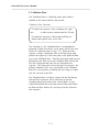
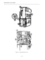
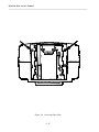
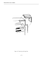
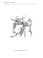
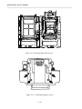
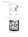
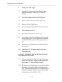
Figure 4-1 Removing Front Cover
4 - 12
Polaroid ID-4 Service Manual
C.
Level 1 Parts Removal
This section first describes the removal of the Front Cover and
the following group of associated parts (Fig. 4-1, top):
1.
2.
3.
4.
5.
Grip Clip (inside Front Cover)
Hand Grips
S1 Button
Shutter Bezel
Aim Light Cover
The next section next covers the removal of the following parts
which are accessible after th e removal of the Front Cover
(Fig. 4-1, bottom):
6.
7.
8.
9.
10.
11.
Face Strobe Reflector Assembly
Aim Light Assembly
Face Brightener Solenoid Assembly
Transducer and Ranging Board
Shutter Solenoid Assembly
Data Card Sensor Cable Assembly
Note: Before attempting any parts removal, lift the
Camera Head off the base and place on a suitable
work area.
4 - 13
Polaroid ID-4 Service Manual
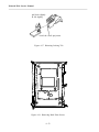
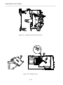
Figure 4-2 Removing Grip Clip
4 - 14
Polaroid ID-4 Service Manual
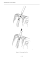
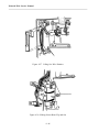
1.
Front Cover
1.1
Remove Data Card Holder.
1.2
Remove the Grip Clip.
Hold Camera firmly on side with Data Card Holder
opening up. Insert Grip Clip Removal Tool through
opening and into the end of Grip Clip. (Fig. 4-2, top)
Push downward on Tool and at same time rotate
toward the f ront of Camera to release Grip Clip.
(Fig. 4-2, bo ttom)
4 - 15
Polaroid ID-4 Service Manual
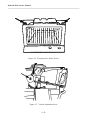
Figure 4-3 Removing Hand Grips
4 - 16
Polaroid ID-4 Service Manual
1.3
Remove Hand Grips.
Use a screwdriver to press down on the cover clips
to release the plastic tips from the front cover
(Fig. 4-3). Rotate Grip backward to remove.
1.4
Remove the blue S1 button.
1.5
Remove shutterbezel by p ulling straight out.
1.6
Remove Aim Light Cover by pushing in the side
on top and sliding off.
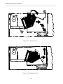
1.7
Loosen (do not remove) two screws on Base
Plate nearest connector. (Fig. 4-4)
1.8
Remove two recessed screws at top of Back
Cover. (Fig. 4-5)
1.9
Remove front cover.
4 - 17
Polaroid ID-4 Service Manual
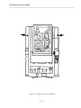
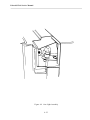
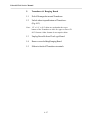
Figure 4-4 Loosening Base Plate
4 - 18
Polaroid ID-4 Service Manual
Figure 4-5 Back Cover Screw Removal
4 - 19
Polaroid ID-4 Service Manual
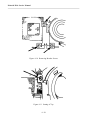
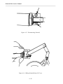
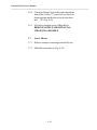
Figure 4-6 Loosening Face Strobe Screws
Figure 4-7 Vertical Adjustment Screw
4 - 20
Polaroid ID-4 Service Manual
2.
Face Strobe Reflector Assembly
2.1 Slide out insulating paper on aim light side of strobe.
2.2 Loosen two screws at top of bracket. (Fig. 4-6)
2.3 Unplug connector – slide Assembly up and out.
3.
Aim Light Assembly
3.1 Disconnect plug from J11 on Logic Board.
3.2 Loosen (do not remove) Vertical Adjustment Screw
shown with 3/32" ball-end Allen wrench. (Fig. 4-7)
3.3 Pivot Assembly straight up and lift off.
(See Figs. 4-8 & 4-9)
4 - 21
Polaroid ID-4 Service Manual
Figure 4-8 Removing Aim Light Door
4 - 22
Polaroid ID-4 Service Manual
Figure 4-9 Aim Light Assembly
4 - 23
Polaroid ID-4 Service Manual
Figure 4-10 Removing Bracket Screws
Figure 4-11 Seating of Top
4 - 24
Polaroid ID-4 Service Manual
4.
Face Brightener Solenoid Assembly
4.1 Remove three screws from bracket. (Fig. 4-10)
4.2 Disengage bracket from arm.
4.3 Remove Solenoid, spring and plunger.
4.4 Unplug Solenoid cable from J1 on Logic Board
Note: When remounting bracket, seat top fully down on
top post shoulder. (Fig. 4-11)
4 - 25
Polaroid ID-4 Service Manual
Figure 4-12 Unlocking Transducer Tabs
4 - 26
Polaroid ID-4 Service Manual
5.
Transducer & Ranging Board
5.1
Peel off foam gasket around Transducer.
5.2
Unlock tabs at topand bottom of Transducer.
(Fig. 4-12)
Note: 1/2" x 1/8" x .010" shims are used under the top or
bottom of the Transducer to tilt it for upper or lower CR
80/79 formats. Other formats do not require shims.
5.3
Unplug flex cable from J2 on Logic Board.
5.4
Remove screw holding Ranging Board.
5.5
Slide wire leads off Transducer terminals.
4 - 27
Polaroid ID-4 Service Manual
Figure 4-13 Disconnecting Solenoid
Figure 4-14 Sliding Solenoid Body Off Cover
4 - 28
Polaroid ID-4 Service Manual
6.
Shutter Solenoid Assembly
6.1
Disconnect Solenoid cable from J7 on Logic
Board.(Fig. 4-13)
6.2
Remove two screws holding bracket to Base
Block.
6.3
Slide Solenoid body off plunger ("d"). (Fig. 4-14)
Note: When reinstalling Shutter Solenoid Assembly, perform
the "Setting the Shutter Linkage" procedure described
later under "Adjustment Procedures."
7.
Data Card Sensor Cable Assembly
7.1
Unplug connector J6 from Logic Board.
7.2
Release locking tab on bottom of Sensor (next to
orange and red wires) and slide connector out.
4 - 29
Polaroid ID-4 Service Manual
Figure 4-15 Removing Back Plate Screws
Figure 4-16 Loosening Baseplate Screws
4 - 30
Polaroid ID-4 Service Manual
D.
Level 2 Parts Removal
1.
Back Cover
(Front Cover must be off)
1.1
Unplug black ground wire from J4 on Face Strobe
Board.
1.2
Disconnect ribbon cables from J3 and J12on
Logic Board.
1.3
Remove six screws from Back Plate. Slide Camera
Back half-way down and open door to gain access
to top and middle screws. (Fig. 4-15)
1.4
Loosen (do not remove) four screws in Baseplate,
(Fig. 4-16)
1.5
Lift Back Cover off Main Frame.
2.
Counter
2.1
Disconnect Counter cable plug from Display
Board, J3.
2.2
Squeeze locking tabs in on sides of Counter and
push Counter out through opening in Back Cover.
4 - 31
Polaroid ID-4 Service Manual
pull back slightly
& lift slightly
Avoid the small projection
Figure 4-17 Releasing Locking Tab
Figure 4-18 Removing Back Plate Screws
4 - 32
Polaroid ID-4 Service Manual
3.
S1 (Shutter ) Switch Assembly
3.1
Disconnect cable plug from Display Board, J1.
3.2
Remove tape from cable (note position).
3.3
Remove connector from switch. (Do this from the
outside of the camera.)
3.4
Release locking tab at bottom of Switch. (Fig. 4-17)
3.5
Lift switch out of back cover (Fig. 4-17)
4.
Display Board
4.1
Disconnect cables connected to the Board.
4.2
Remove two nutsholding board in place.
4.3
Push board from inside: press first near J2 (middle
jack) to release one end of the Board, then press at
other end.
5.
Back Plate Assembly
5.1
Remove the five screws. (Fig. 4-18)
5.2
Lift off Back Plate.
5.3
Remove Wear Strip (metal or plastic) from track and
note its position.
Note: When replacing Back Plate Assembly, if Wear Strip is
metal, install it with sharp edge next to the housing,
smooth edge against the Camera.
4 - 33
Polaroid ID-4 Service Manual
Figure 4-19 Removing Latch Mechanism and Camera Back Stop Screws
Figure 4-20 Removing Retaining Bracket Screws
4 - 34
Polaroid ID-4 Service Manual
6.
Latch Mechanism
6.1
Remove the two screws holding it. (Fig. 4-19)
7.
Camera Back Stop
7.1
Remove the two screws holding it. (Fig. 4-19)
8.
Base Slide Spacer Assembly
8.1
With the latch mechanism and Camera Back
removed, slide the Base Slide Spacer off of the
Back Plate Assembly.
9.
Validation Plate Solenoid
9.1
Peel off light seal felt.
9.2
Remove two screws from retaining bracket. (Fig. 4-20)
4 - 35
Polaroid ID-4 Service Manual
Figure 4-21 Removing Base Slide Spacer Assembly Screws
4 - 36
Polaroid ID-4 Service Manual
10.
Camera Back from Base Slide Spacer
Assembly
10.1 Remove eight screws located inside assembly. This
also givesaccess to the PullFilm Switch. (Fig. 4-21)
11.
Logic Board
11.1
Unplug all cables connected to Logic Board.
Connections include the following, which arealso
shown pictorially in the accompanying Camera
HeadWiring Diagram, Schematic A-3(see Appendix).
J1 - Face Brightener Solenoid
J2 - Ranging Module
J3 - Display Board
J4 - Data Strobe (Timing) Board
J5 - Face Strobe Board
J6 - Data Card Sensors
J7 - Shutter Solenoid and Shutter Sync Contacts
J8 - Sensor Board
J9 - Empty (for external computer RS232)
J10 - Mirror Motor Drive Board
J11 - Aim Light
J12 - Display Board
11.2 Remove the screw or retaining key holding Logic
Board, release latch, slide Board toward topof
Camera, pivot board up and out.
4 - 37
Polaroid ID-4 Service Manual
Notes
4 - 38
Polaroid ID-4 Service Manual
12.
Face Strobe Board
12.1 Remove two connectors (J12 and J13) from Face
Strobe Board.
12.2 Remove screw and spacer holding Face Strobe
Board, release latch, slide Board toward topof
Camera, up and out.
13.
Data Strobe Boards
(Quench and Timing) (See Schematic A-8,
Appendix.)
13.1 Remove insulation paper from Data Strobe Board
(note position).
13.2 Disconnect six wire leadsto Data Flashtubes.
CAUTION: NEVER FIRE DATA STROBES WITH
FLASHTUBES DISCONNECTED. THIS CAN DESTROY
THE BOARD!
13.3 Remove two screws holding Data Strobe Board.
4 - 39
Polaroid ID-4 Service Manual
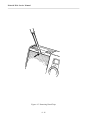
Figure 4-22 Removing Screws from Motor Drive Bracket
4 - 40
Polaroid ID-4 Service Manual
14.
Upper (moveable) Mirror
14.1 Press lock tabs away from Mirror back (toward
Motor) and slide Mirror up and out.
15.
Motor Drive
15.1 Remove two screws from bottom of Bracket. (If
both screws are notvisible, move Mirror Carrier
out of the way: rotate gear train by turning gear
near Motor with finger.) (Fig. 4-22)
4 - 41
Polaroid ID-4 Service Manual
Figure 4-23 Rotating Cam Pivots Into Position
Figure 4-24 Sliding Carrier
4 - 42
Polaroid ID-4 Service Manual
16.
Mirror Carrier
16.1 Remove Data Lens.
16.2 If Motor Drive is present, rotate gears manually
(see 15.1) until campiv ots arein position shown
(out of the Carrier channels). (Fig. 4-23)
16.3 Slide Carrier to right (toward base of Camera)
and lift slightly so that projecting tab "A"on
Carrier slides past projection "B" on Base
Block. (Fig. 4-24)
4 - 43
Polaroid ID-4 Service Manual
Figure 4-25 Freeing Carrier
Figure 4-26 Sliding Mirror Up
4 - 44
Polaroid ID-4 Service Manual
16.4 Continue sliding Carrier to the right, then tilt the
front of the Carrier "C" (part closest to the lens)
downward toward the lens to free it from channels "D". (Fig. 4-25)
16.5 Lift Carrier straight up out of Base Block.
REMOVE SLOWLY AND LIFT OUT AS
STRAIGHT AS POSSIBLE.
17.
Lower Mirror
17.1 Push in (compress) retaining bar and lift it out.
17.2 Slide Mirror up and out. (Fig. 4-26)
4 - 45
Polaroid ID-4 Service Manual
Figure 4-27 Lifting Out Wire Retainer
Figure 4-28 Sliding Sensor Board Up and Out
4 - 46
Polaroid ID-4 Service Manual
18.
Photo Sensors
18.1 Lift out Wire Retainer. (Fig. 4-27)
18.2 Lift out Sensors: grasp beyond Retaining Clip.
18.3 Slide Sensor Board with attached Sensors up and
out. (Fig. 4-28)
4 - 47
Polaroid ID-4 Service Manual
Notes
4 - 48
Polaroid ID-4 Service Manual
19.
Face Polarizer
(Can be removed from assembled Camera through
Camera Back Door.)
19.1 Cycle camera to mirror up (face taking) position.
19.2 Insert tipof Face Polarizer RemovalTool under
Polarizer lipand pry up carefully.
Notes on replacing the Face Polarizer
1. Place the Face Polarizer over the rear lens, with the
notch on the Polarizer over the stud on the housing.
Be careful not to break the stud.
2. Place the Face Polarizer Installation Tool (P/N
11522) over the Polarizer - make sure it is centered.
3. Tilt the Tool handle slightly and apply pressure to
seat one of the Polarizer securing tabs.
4. With a rocking motion of the handle, press down
and seat each of the Polarizer tabs in succession. A
click will be heard as each tab seats.
4 - 49
Polaroid ID-4 Service Manual
Notes
4 - 50
Polaroid ID-4 Service Manual
20.
Shutter Assembly
20.1 Cycle camera to mirror up (face taking)
position.
20.2 Remove face polarizer. (Can be removed from
assembled Camera through Camera Back
Door.)
20.3 Disconnect Sync Chord at Shutter
20.4 Remove Shutter Retaining Ring (and Back-up
Washer) with Shutter Removal Tool P/N 11523.
Lift Shutter Assembly Linkage out of Baseblock.
20.5 Linkage rivets may be removed and/or
replaced using the following tools:
P/N 13433
P/N 13440
P/N 13439
Rivet Fixture
Rivet Installer
Rivet Remover
4 - 51
Polaroid ID-4 Service Manual
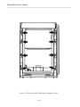
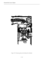
Figure 4-29 Removing Baseblock from Main Frame
4 - 52
Polaroid ID-4 Service Manual
E.
Level 3 Parts Removal
(Main Frame and Baseblock)
1.
To Separate Main Frame from Baseblock
1.1
Pull wire leads from Data Flashtubes through slot in
Main Frame. (Note: This slot may be enlarged using
needle-nose pliers to a 'v-slot' to ease wire routing.)
1.2
Remove six screws holding Baseblock to Main
Frame, exposing Data Flashtubes on opposite side of
Baseblock. (Fig. 4-29)
4 - 53
Polaroid ID-4 Service Manual
Figure 4-30 Lifting Out Flashtubes
Figure 4-31 Removing Horizontal Reflectors
4 - 54
Polaroid ID-4 Service Manual
1.3
Flashtubes are held in place by grommets at ends.
Lift out Flashtubes by gentlypulling up on wi resat
each end. (Fig. 4-30)
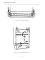
1.4
Slide out Flash Channels and Parallel Reflectors.
1.5
In the Main Frame, remove Horizontal Reflectors
by sliding themdown and out. (Fig. 4-31)
4 - 55
Polaroid ID-4 Service Manual
(Shutter - Side View)
Energized
Position
Trip
Point
.025"
.030"
Pivot "X"
Trip Lever
Link Stop
Figure 4-32 Setting Shutter Linkage
4 - 56
Polaroid ID-4 Service Manual
F.
Adjustment Procedures
1.
Setting the Shutter Linkage
1.1
Loosen screwholding Shutter Link Stop and adjust
its position to allowa gap of approximately 0.025"
- 0.030" between the Shutter Trip Lever and end of
the opening in the Shutter housing. (Fig. 4-32)
1.2
Retighten the Link Stop screw. (Be sure Trip Lever
travels far enough to trip Shutter.)
Note: The purpose of this adjustment is to prevent Trip Lever
from striking Shutter housing when tripped.
1.3
Loosen screws in Solenoid bracket.
Position the Solenoid body so that when plunger is
all the way in (energized position), linkagepivot
"X" is at the right end of the slot, as shown in the
illustration (Fig. 4-30).
4 - 57
Polaroid ID-4 Service Manual
Figure 4-33 Holding Shutter Blades Open
Figure 4-34 Sharpening Aim Light Image
4 - 58
Polaroid ID-4 Service Manual
2.
Setting the Aim Light
2.1
Set up the ID-4 Camera the correct distance from a
white wall (or target) – either 54" (137 cm)or 40"
(102cm).
2.2
Turn Face Brightener Bezel to Full Lighten.
2.3
Remove the Lens Bezel (or Close-up Lens).
2.4
Remove the Aim Light Cover.
2.5
Insert Aiming Val Plate (P/N 11535) into Camera.
2.6
Turn Camera power ON.
2.7
Insert Data Card (to move mirror up).
2.8
As you depress the Face Fire Button S1, insert the
end of a large paper clip in the hole in the Shutter,
to hold the blades open (see illustration). (Fig. 433)
2.9
Immediately shut offthe power before the mirror
moves down.
2.10 Attach an 8-10V DC power supply to the Aim
Light bulb leads.
CAUTION: POWERING THE BULB WITH OVER 12V
CAN SHORTEN BULB LIFE.
2.11 Observe the position of the AimLight beam spot
on the Test Val Plate. Adjust it to the proper position with a 3/32" ball-end Allen wrench.
2.12 The sharpest Aim Light image occurs when the bulb
filament axis coincides with the Aim Light optical
axis. If the bulb filament axis is off, bend the base of
the Bracket slightly with pliers, observing the effect
on the image on the wall. (Fig. 4-34)
4 - 59
Polaroid ID-4 Service Manual
OFF
ON
1
Data Card
Override
2
Far – Near
3
Moveable
Back 1
4
Moveable
Back 2
Figure 4-35 Setting the DIP Switch S2
4 - 60
Polaroid ID-4 Service Manual
2.13 Always take a test picture after setting the Aim
Light, to verify that the setting is correct.
3.
Setting the DIP Switch S2
(Refer to Fig. 4-35, opposite)
3.1
Position 1 should be OFFif only one Data Card
exposure is to be made by inserting a Data Card
(One-up format), or ON if a second exposure of
the same card is to be made automatically when
the Camera Back is moved to thedown position
(i.e., the data card need not be pulled out and
reinserted).
3.2
Position 2 should be OFFif Standard Lens is in use
(54" or 137 cm to subject), ON if No. 663 CloseUp Lens is in use (40" or 102 cm to subject).
3.3
Set Sections 3 and 4 of this Switch together,
according to the type of Camera Back being used:
• Moveable Back (Two-up format):
S2-3 and S2-4 both ON
• Non-Moveable Back (One-up format):
S2-3 and S2-4 both OFF
4 - 61
Polaroid ID-4 Service Manual
Notes
4 - 62
Polaroid ID-4 Service Manual
4.
Focusing the Face Lens
Note: If the subject image is not sharp on the ID card, or the
Shutter/Lens Assembly has been removed or replaced,
refocusing may be necessary.
4.1
Install thespecial Ground Glass FilmPack P/N11534 in
thefilm compartment.
4.2
Lock Shutter open.
(see previous section "Setting AimLight")
4.3
Set Camera so lens is exactly 54" (137cm) from
Lens Resolution Target P/N 11520.
4.4
Check image on ground glass with 7X or stronger
loupe. If lens is properly focused, ground glass
image should be sharp (28 lines/mm is the spec). If
not sharp, proceedas follows.
4.5
Manually loosen the front lens element assembly.
DO NOT USE TOOLS!
Note: You may need to apply a few drops of methanol to the
threads of the front element to free the cement which
prevents it from turning.
4.6
Rotate front lens element until sharpest possible
image occurs.
4.7
When satisfied that image is sharpest, apply a drop
of Duco Cement in the threads to secure the lens
setting.
4 - 63
Polaroid ID-4 Service Manual
Notes
4 - 64
Polaroid ID-4 Service Manual
5.
Replacing the Face Polarizer
5.1
Place the Face Polarizer over the rear lens, with
the notch on the Polarizer over the stud on the
housing. Be careful not to break the stud.
5.2
Place the Face PolarizerInstallation Tool
(P/N 11522) over the Polarizer – make sure it is
centered.
5.3
Tilt the Tool handle slightly and apply pressure to
seat one of the Polarizer securing tabs.
5.4
With a rocking motion of the handle, press down
and seat each of the Polarizer tabs in succession.
A click will be heard as each tab seats.
4 - 65
Polaroid ID-4 Service Manual
G.
Camera Wire Routing
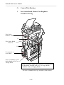
1.
Face Strobe Board, Shutter, Face Brightner,
Transducer Wiring
Face Strobe
Reflector Cable
J5
Face Strobe Board
794075/A
J13
To connector on
Power Base
From J12 (hidden) on Face
Strobe Board to E4-47 on
Timing Board
Shutter Solenoid & Shutter Sync leads (to J7 on Logic Board)
Face Brightener Solenoid leads (to J1 on Logic Board)
Transducer leads (to Ranging Board)
All wires in channel below lips, secured by foam retainer
4 - 66
Polaroid ID-4 Service Manual
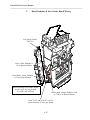
2.
Data Flashtube & Face Strobe Board Wiring
Face Strobe Board
794075/A
Green (from flashtube to
J4 on Quench Board)
Green/White (from flashtube
to J6 on Quench Board)
When replacing Face Strobe Board,
be sure wires are not pinched
by solder side of Board
White (high voltage flashtube leads
to J3 & J5 on Quench Board)
From E1-E5 and E6 & E7 on Face
Strobe Board to J5 on Logic Board
4 - 67
Polaroid ID-4 Service Manual
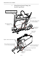
3.
Wiring Between Quench, Timing, Face
Strobe & Logic Boards
Replace carefully in notch
to prevent damaging insulation
Green/White
White High Voltage leads
to Data Flashtubes
Green
Data Quench Board
798238/A
J3
J6
J5
Timing Board
798236/A
J4
Logic Board
794238A
Replace cables under these pins
From connector on Power Base
to J13 on Face Strobe Board
From E1-E5 and E6 & E7
on Face Strobe Board
E1-E3 to J4 on Logic Board
E4-E7 to J12 on
Face Strobe Board
Timing Board
79236/A
4 - 68
Polaroid ID-4 Service Manual
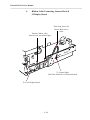
4.
Ribbon Cable Connecting Camera Back &
J2 Display Board
Slack loop allows for
Camera Back movement
Replace ribbon cable
between case and molded pins
To Camera Back
(Pull Film Switch & Val Plate Solenoid)
To J2 on Display Board
4 - 69
[This page intentionally blank]
Polaroid ID-4 Service Manual
APPENDIX
SCHEMATICS
Polaroid ID-4 Service Manual
Notes
Polaroid ID-4 Service Manual
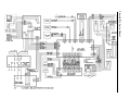
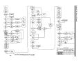
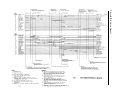
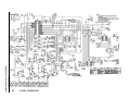
Appendix - Schematics
Table of Contents
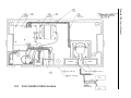
Base Unit Wiring Diagram................................................... A-1
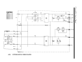
Power Supply Unregulated ................................................... A-2(1)
Base Assembly Wiring Diagram .......................................... A-2(2)
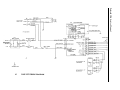
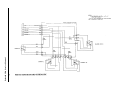
Camera Head Wiring Diagram ............................................ A-3
System Program Flow Chart ................................................ A-4
System Timing Chart ........................................................... A-5
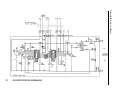
Logic Schematic ................................................................... A-6
Photo Sensor Board Schematic ............................................ A-7
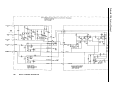
Data Strobe Doubler ............................................................. A-8
Ranging Module Schematic ................................................. A-9
Polaroid ID-4 Service Manual
Polaroid ID-4 Service Manual
Polaroid ID-4 Service Manual
Polaroid ID-4 Service Manual
Polaroid ID-4 Service Manual
Polaroid ID-4 Service Manual
Polaroid ID-4 Service Manual
Polaroid ID-4 Service Manual
Polaroid ID-4 Service Manual
Polaroid ID-4 Service Manual
[This page intentionally blank]