1
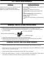
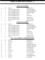
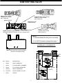
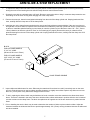
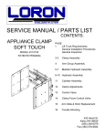
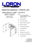
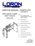
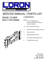
SERVICE MANUAL / PARTS LIST
BASIC CLAMP
BOLT-ON ARMS
CONTENTS:
PAGE
1
Lift Truck Requirements
General Installation Procedures
General Inspection
2-3
Basic Clamp Parts Group
4
Clamp Cylinder Assembly & Service
5
Valve Assembly
6
Adjusting Relief Pressure
7
Arm Slide & Shim Replacement
8
Troubleshooting Guide
425 Hazel St.
Kelso WA 98626
(800) 248-6079
Fax (360) 578-9934
LIFT TRUCK REQUIREMENTS
CAPACITY
CLAMP HYDRAULICS
Capacity shown on the Clamp name plate is for the
Clamp only. the combined truck and Clamp
capacity is provided by the lift truck manufacturer.
Recommended Truck Pressure: 1700 to 2500 PSI
(115 to 170 bar)
Oil volume: 6-10 GPM (22.5 to 38 l/min)
Hydraulic fluid: petroleum based hydraulic fluid
only
Hydraulic supply group: includes hoses and
take-up - one set for each function
Auxiliary valve:
2 Function (Side Shift & Clamp) = a double auxiliary
valve
GENERAL INSTALLATION PROCEDURES
1. Make sure that the attachment centering lug is completely seated in truck carriage center notch.
2. Clearance between the lower retainers that hold the attachment to the truck lower carriage bar should
be as shown below.
.13" (3.2mm) MAXIMUM
TRUCK LOWER CARRIAGE BAR
LOWER RETAINER
3. Attach truck supply group (take-up) to clamp valve on attachment base.
4. Standing clear of the Clamp attachment cycle the attachment in and out several times. Use caution
because partially filled hydraulic lines may cause erratic movement.
GENERAL INSPECTION AND MAINTENANCE
1. Check all hydraulic fittings, hoses, cylinders and valves for leakages - repair or replace as required
2. Check hoses for pinch points and signs of wear. Replace worn hoses with LORON hose or Parker
Parflex # 560 wire - reinforced hose only.
3. All bolts should be checked and tightened as required. See Torque Note page 2.
4. Check lower retainer clearance - see item 2 in General Installation Procedures above. A shim may be
tack-welded to the bottom of the lower retainers to tighten the clearance if necessary.
1
BASIC CLAMP PARTS GROUP - 1
TORQUE SPECIFICATION (LUBRICATED)
1
1.00" DIA BOLT - 675 FT-LBS (93.4KG-M)
9
.88" DIA BOLT - 450 FT-LBS (62.2 KG-M)
10
SEE CLEARANCE NOTE
PAGE 4
12
11
2
13
14
7
15
16
17
18
19
6
3
5
8
4
2
BASIC CLAMP PARTS GROUP - 2
L20 & L25 CLAMPS
#
QTY
1
PART #
DESCRIPTION
1
SEE CUSTOMER PACKET
FRAME WELDMENT
2
2
SEE CUSTOMER PACKET
CYLINDER ASSEMBLY
3
4
SEE CUSTOMER PACKET
ARM WELDMENT
4
8
SEE CUSTOMER PACKET
SHIM
5
4
SEE CUSTOMER PACKET
FLAT SLIDE
6
8
SEE CUSTOMER PACKET
ANGLE SLIDE
7
1
SEE CUSTOMER PACKET
FRONT COVER
8
12
103752
SLIDE BUTTON
L35 & L50 CLAMPS
#
QTY
1
PART #
DESCRIPTION
1
SEE CUSTOMER PACKET
FRAME WELDMENT
2
2
SEE CUSTOMER PACKET
CYLINDER ASSEMBLY
3
4
SEE CUSTOMER PACKET
ARM WELDMENT
4
8
SEE CUSTOMER PACKET
SHIM
5
4
SEE CUSTOMER PACKET
FLAT SLIDE
6
8
SEE CUSTOMER PACKET
ANGLE SLIDE
7
1
SEE CUSTOMER PACKET
FRONT COVER
8
12
107997
SLIDE BUTTON
L20 - L50 CLAMPS - COMMON PARTS
#
QTY
9
PART #
DESCRIPTION
4
100574.86
COTTER PIN
10
4
101333
SLOTTED NUT
11
4
100047
HARDENED WASHER
12
4
101324
SPHERICAL BEARING
13
2
1C.0612
HEX HEAD BOLT
14
2
4E.06
LOCK WASHER
15
2
100572.060
BALL-LOCK PIN
16
2
101098
LOWER RETAINER
17
2
16E.06
LOCK WASHER
18
2
11G.0612
SOCKETHEAD BOLT
19
2
100077.3
ROUND BAR
3
CYLINDER ASSEMBLY
9
10
11
15
13
SAE #6
O-RING
PORTS
4
12
2
1
CLEARANCE NOTE:
.03/.06 EACH CYLINDER END ADJUST SLOTTED NUT TO ALLOW FOR
CLEARANCE AS SHOWN. INSERT COTTER PIN AFTER ADJUSTMENT.
L35 & L50 CLAMP CYLINDER
#
6
14
8
CYLINDER
ANCHOR
REF.
3
7
QTY PART #
L20 & L25 CLAMP CYLINDER
DESCRIPTION
1
CONSULT FACTORY CYLINDER ASSEMBLY
1
1
CONSULT FACTORY TUBE
2
1
3
#
QTY PART #
DESCRIPTION
1
CONSULT FACTORY CYLINDER ASSEMBLY
1
1
CONSULT FACTORY TUBE
CONSULT FACTORY ROD
2
1
CONSULT FACTORY ROD
1
100021
PISTON
3
1
101256
PISTON
4
1
100020
GLAND
4
1
101254
GLAND
5
1
101036
SEAL KIT (NOT SHOWN)
5
1
101261
SEAL KIT (NOT SHOWN)
6
1
101035
MODIFIED ESNA NUT
6
1
101035
MODIFIED ESNA NUT
7
1
100032.107
POLY PAK LSP
7
1
100032.095
POLY PAK LSP
8
1
100031.059
POLY PAK LSP
8
1
100031.059
POLY PAK LSP
9
1
100028.316
BACK-UP O-RING
9
1
100028.314
BACK-UP O-RING
10
1
100029.316
O-RING LSP
10
1
100029.314
O-RING LSP
11
1
100033
WEAR RING LSP
11
1
101260
WEAR RING LSP
12
1
101034.6
WIPER LSP
12
1
101034.6
WIPER LSP
13
1
100027.1
LOCKWIRE
13
1
100027.2
LOCKWIRE
14
1
100029.203
O-RING LSP
14
1
100029.203
O-RING LSP
15
1
CONSULT FACTORY SPACER
15
1
CONSULT FACTORY SPACER
CYLINDER SERVICE
Prior to assembly lubricate seals, cylinder bore and rod with STP.
Inspect all parts for scratches, nicks and gouges- -replace all damaged components.
Inspect cylinder bore and rod for scoring- -replace if scored
Avoid damage to seal grooves- -use a dull screwdriver for seal removal
Torque piston nut to 200 FT/LBS.
4
SIDE SHIFTING VALVE
103813 FLOW DIVIDER
TORQUE 10-12 FT/BLS
104711 SEAL KIT
104721 ORIFICE
G
103815 BIDIRECTIONAL RELIEF
TOQUE TO 35/40 FT/LBS
104716 SEAL KIT
F
B
101419.03 #4 SAE
O-RING PLUGS
A
E
D
C
103815.1 BIDIRECTIONAL RELIEF
SEE103815 ABOVE FOR SEAL KIT AND TORQUE NOTE
103814 P.O. CHECK
TORQUE 35/40 FT/LBS
104715 SEAL KIT
NOTE:
1. Lubricate threads & seals prior to assembly.
2. For VALVE pressure changes See page 7.
HYDRAULIC SCHEMATIC
100011 SIDE SHIFTING VALVE ASSEMBLY
(Includes all cartridges & plugs)
C1
C4
C3
C2
SS2
103815
850PSI
B
C
D
QTY PART #
103814
(3)
DESCRIPTION
1
103815
RELIEF CARRIAGE
1
103813
FLOW DIVIDER / COMBINER
3
103814
P.O. CHECK CARTRIDGES
1
103815.1
RELIEF CARTRIDGE
14
101419.03
#4 SAE O-RING PLUG LSP
104721
ORIFICE
1
E
F
G
103813
104721
103815.1
1700PSI
5
A
SS1
ADJUSTING RELIEF PRESSURE
WARNING:
RELEASE TRUCK PRESSURE PRIOR TO SERVICING
VALVE BY TURNING THE TRUCK OFF AND "WORKING"
THE SIDE SHIFT AND CLAMP FUNCTION CONTROLS
REMOVE CAP - REPLACE CAP PRIOR
TO PRESSURIZING SYSTEM
TURN ADJUSTMENT:
COUNTERCLOCKWISE TO DECREASE PRESSURE
CLOCKWISE TO INCREASE PRESSURE
DO NOT EXCEED 2000 PSI (136 BAR)
ADJUSTING SYSTEM PRESSURE
1.
Release system pressure prior to servicing valve by turning the truck off and working the side shift and clamp function
controls several times.
2.
Prior to adjusting system pressure, disconnect the hoses from the clamp valve at the "open" and "close" ports. Install a
separate in-line tee with a short hose and a pressure gauge that is calibrated to 5000 psi (340 bar) in each port (two
required). Reconnect hoses.
3.
Measure system pressure by securely clamping a load or close the clamp arms all the way and hold the control and hold the
control lever in the closed (clamped) position. The actual clamping pressure is the difference between the pressure shown
on the gauge in the "open" port subtracted from the pressure shown on the "close" port gauge.
4.
Release system pressure (see step 1). Remove cap on bidirectional valve (item #4 on side shifting valve) and adjust
cartridge no more than one quarter turn. Replace cap prior to pressurizing system. Repeat until desired pressure setting is
achieved. Do not exceed 2000 psi (136 bar) clamping pressure.
ADJUSTING BY-PASS PRESSURE
1.
If on arm bottoms out and the other moves more then 3" (76mm) before opening fully, increase by-pass relief pressure. If
one arm bottoms out and the other dose not open fully, decrease by-pass pressure.
2.
To adjust by-pass relief pressure, release system pressure prior to servicing valve by turning the truck off and working the
side shift and clamp function control several times.
3.
Remove cap on bidirectional valve (item #1 on side shifting valve) and adjust cartridge no more than one quarter turn.
Replace cap prior to pressurizing system. Repeat until desired pressure setting is archived. Do not exceed 2000 psi (136
bar)
6
ARM SLIDE & SHIM REPLACEMENT
1.
To replace the slides extend the arms to the fully open position. Release system pressure prior to removing the arms by
turning the truck off and working the side shift and clamp function controls several times.
2.
Support the arm with an overhead crane or lift truck. Be sure to secure the chain or sling in a manner that prevents the arm
from falling out of the chain or sling when hanging free of the clamp frame.
3.
Remove the cotter pin, slotted nut and spherical bearing from the end of the clamp cylinder rod. Keeping hands and feet
clear, carefully slide the clamp arm off of the clamp frame.
4.
Install the arm on the clamp frame ensuring that the arm moves freely without excessive binding. If the arm is too loose or
too tight add or remove shims as required. Once the clearance is satisfactory insert the cylinder rod into the cylinder anchor
on the arm. Install the spherical bearing, nut and cotter pin onto the cylinder rod end. Be sure to leave .03" - .06" (.7mm to
1.5mm) clearance to allow the cylinder to "float" on it's mountings (see page 4).Remove the cotter pin, slotted nut and
spherical bearing from the end of the clamp cylinder rod. Keeping hands and feet clear, carefully slide the clamp arm off of
the clamp frame.
BLOCK:
FOR L20 CLAMP MODELS
2" X 2" X 3" LONG
(50.8mm X 50.8 mm X 76mm)
FOR L35 CLAMP MODELS
2.25" X 2.25" X 3" LONG
(57.2mm X 57.2mm X 76mm)
ARM
CLAMP FRAME ARM BAR
5.
Inspect slides and slide buttons for wear. Slides may be rotated end-for-end and re-used if excessively worn on the outer
end only. Extra shims may be used to tighten operating clearance on slightly worn slides. Replace any slides worn to less
than .06" (1.5mm) thick or any slide that is deeply scored or broken.
6.
To aid in replacing the slides a block may be fashioned of wood or another convenient material to the dimensions shown
above. The block is inserted in the end of the arm to hold the slides, shims and buttons in position while the arm is inserted
over the arm bars on the clamp frame. The block is expelled out the opposite end of the arm as the arm is pushed onto the
frame.
7.
Prior to installing the arm the block may be used to determine the number of shims to place under the slides. Adjust the
clearance between the slides and the block to provide approximately .06" (1.5mm) running clearance between the slides and
arm when installed.
7
TROUBLE SHOOTING GUIDE
LOADS SLIPPING OR DROPPING
POSSIBLE CAUSES
SOLUTIONS
1.
Valve cartridges not sufficiently tight
1.
Tighten all cartridges to torque values shown on page 6
2.
System relief pressure set too low
2.
See Adjusting System Pressure page 7
3.
Internal leakage in cylinder
3.
Replace Cylinder seals. If tube, piston or rod scored
replace with new parts.
4.
Incorrect clamp pad size or load not fully engaged in
clamp arms
4.
Be sure the clamp pads are correctly sized and the load
for the load and the load is positioned fully in the clamp
arms
5.
Pad camber set incorrectly
5.
Shim pads to change camber
6.
Load to heavy for clamp capacity
6.
Consult factory
7.
Load may not by stacked correctly or may need to be
unitized
7.
Re-stack or unitize load (shrink wrap)
8.
Bent arms or contact pads
8.
Consult factory
CRUSHING LOADS
POSSIBLE CAUSES
SOLUTIONS
1.
System relief pressure set too high
1.
See Adjusting System Pressure page 7
2.
Operator over-working (milking) control valve
2.
Once the pad contact the load, clamp the load in one
even motion - do not over-work the valve
3.
Bent arms or contact pads
3.
Consult factory
4.
Pad camber set incorrectly
4.
Shim pads to change camber
5.
Variable loads that require different clamping pressures
5.
Install a 4-position pressure regulator on truck cowl consult factory for part number and availability
8