1
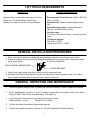
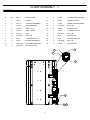
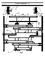
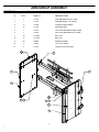
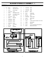
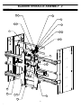
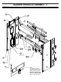
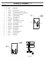
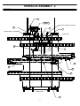
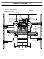
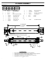
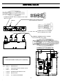
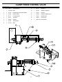
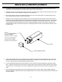
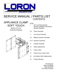
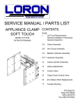
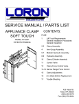
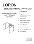
SERVICE MANUAL / PARTS LIST
CONTENTS:
APPLIANCE CLAMP
SOFT TOUCH
MODEL #111348
PATENTS PENDING
PAGE
1
Lift Truck Requirements
General Installation Procedures
General Inspection
2-3
Clamp Assembly
4
Arm Group Assembly
5-7
Bladder Hydraulic Assembly
8-10 Hydraulic Assembly
11
Clamp Cylinder Assembly
12
Clamp Adjustments
13
Control Valve
14
Clamp Force Control Valve
15
Arm Slide & Shim Replacement
16
Trouble Shooting
425 Hazel St.
Kelso WA 98626
(800) 248-6079
Fax (360) 578-9934
LIFT TRUCK REQUIREMENTS
CAPACITY
CLAMP HYDRAULICS
Capacity shown on the Clamp name plate is for the
Clamp only. The combined truck and Clamp
capacity is provided by the lift truck manufacturer.
Recommended Truck Pressure: 2300 to 2500 PSI
(159 to 170 bar)
Hydraulic fluid: petroleum based hydraulic fluid
only
Hydraulic supply group: includes hoses and
take-up - one set for each function
Auxiliary valve:
2 Function (Side Shift & Clamp) = a double auxiliary
valve
Oil Volume Settings:
Side Shift = 3 GPM
Clamp Open/Close = 7 GPM
GENERAL INSTALLATION PROCEDURES
1. Make sure that the attachment centering lug is completely seated in truck carriage center notch.
2. Clearance between the lower retainers that hold the attachment to the truck lower carriage bar should
be as shown below.
.13" (3.2mm) MAXIMUM
TRUCK LOWER CARRIAGE BAR
LOWER RETAINER
3. Attach truck supply group (take-up) to clamp valve on attachment base.
4. Standing clear of the Clamp attachment cycle the attachment in and out several times. Use caution
because partially filled hydraulic lines may cause erratic movement.
GENERAL INSPECTION AND MAINTENANCE
1.
Check all hydraulic fittings, hoses, cylinders and valves for leakages - repair or replace as required
2.
Check bladder/water pressure. If out of operating range adjust as required using Loron Hand
Pump #112909. Check clamp force and adjust. (See page 12.)
3.
Time Schedule: Check pressure and clamp forces every 3 weeks.
Water pressure = 4-6 psi
Clamp Force = 1600lbs
4.
All bolts should be checked and tightened as required.
5.
Check lower retainer clearance - see item 2 in General Installation Procedures above.
1
CLAMP ASSEMBLY - 1
DRAWING REFERENCE 111420
#
QTY
PART #
DESCRIPTION
12
2
111380
CYLINDER ROD WASHER
1
1
111421
FRAME
13
2
107870
LOWER RETAINER
2
2
111714.1
CYLINDER ASSEMBLY
14
1
111423
LOWER LOAD BACKREST
3
1
111439.1
LOAD BACKREST
15
2
11G.1028
BOLT LSP
4
4
111622.1
SLIDE - FLAT
16
12
111619
SLIDE BUTTON
5
8
111621.1
SLIDE - ANGLE
17
1
111222
CYLINDER GUARD
6
12
109212.4
SHIM
18
4
25G.0608
BOLT LSP
7
8
25G.0832
BOLT LSP
19
4
2F.06
WASHER LSP
8
8
4E.08
LOCKWASHER LSP
20
2
4E.10
LOCKWASHER LSP
9
4
111631
BEARING SPHERICAL
21
2
11G.08136
BOLT LSP
10
4
100029.301
ROD CENTERING SEAL
22
2
17D.08
NUT ESNA LSP
11
4
100574.86
COTTER PIN LSP
16
6
4
5
13
21 22
2
CLAMP ASSEMBLY - 2
DRAWING REFERENCE 111420
11
12
3
9
10
7
8
11
1
9
10
19
17
2
14
20 15
3
18
ARM GROUP ASSEMBLY
DRAWING REFERENCE 111164.2
#
QTY
1
PART #
DESCRIPTION
1
111722
ARM WELDMENT RIGHT HAND
2
1
111724
ARM WELDMENT LEFT HAND
3
2
111209
CONTACT PAD (LOWER)
4
20
111031
RETAINING NUT
5
1
111216
TIP PLATE WELDMENT RIGHT HAND
6
1
111218
TIP PLATE WELDMENT LEFT HAND
7
20
1C.0820
BOLT LSP
8
10
1C.0812
BOLT LSP
9
30
108088
SPRING WASHER
10
2
112057
TIP PLATE UPPER
11
2
111210
CONTACT PACT (UPPER)
11
1
2
3
5
10
9
7
9
6
4
6
4
BLADDER HYDRAULIC ASSEMBLY - 1
DRAWING REFERENCE 111440.1
#
QTY
PART#
DESCRIPTION
16
2
111290.0094
HOSE
1
3
111350
AIR TANK VALVE
17
2
111290.0166
HOSE
2
9
111295
HOSE CLAMP
18
2
111290.0114
HOSE
3
1
111290.0025
HOSE
19
24
9G.0412
BOLT
4
1
111296
PRESSURE GAUGE
20
12
111471
CLAMP BAR
5
1
111543.01
21
8
109256
HOSE CLAMP
6
1
111292
BRANCH TEE
22
8
25G.0508
BOLT
7
1
111290.0220
HOSE
23
2
113026.0360
COVER HOSE
8
1
111293
RUN TEE
24
4
111128
HOSE GUIDE
9
1
111290.0180
HOSE
25
12
25G.0512
BOLT
10
1
111290.0082
HOSE
26
1
111085
CLAMP FORCE CONTROL VALVE -REF-
11
1
111290.1170
HOSE
27
1
111289
PIPE ELBOW
12
1
111290.1115
HOSE
28
2
111510
SPRING
13
1
111299
HOSE CLIP
29
24
111878
19 GA. STAINLESS STEEL WIRE TIE
14
1
25G.0516
BOLT
30
2
112391
MODIFIED BLADDER
15
4
111030
BLADDER
0.06
5
BLADDER HYDRAULIC ASSEMBLY - 2
DRAWING REFERENCE 111440.1
2
6
1
2
27 26
3
9
4
13 14
7
8
2
28
11
2
8
12
10
6
5
BLADDER HYDRAULIC ASSEMBLY - 3
DRAWING REFERENCE 111440.1
2
1
30
16
23
19 20
21 22
29
SEE NOTE
25 24
17
15
18
NOTE:
USE TWO 19 GAUGE
STAINLESS STEEL WIRE
TIES (111878) AT EACH
BLADDER CONNECTION TWIST TO TIGHTEN AND
CLIP TO REDUCE ENDS
7
HYDRAULIC ASSEMBLY - 1
DRAWING REFERENCE 111441
#
QTY
PART #
DESCRIPTION
1
1
111193
CLAMP VALVE
2
2
25G.0524
BUTTON HEAD BOLT
3
7
100676.06
STRAIGHT THREAT ADAPTER FITTING
4
2
111518.06
FITTING ADAPTER 04 PIPE - 06 JIC STRAIGHT
5
1
111085
DIRECTIONAL VALVE ASSEMBLY
6
1
100227.05
FITTING UNION TEE
7
1
111123
IN-LINE CHECK VALVE
8
1
103441.0352
HOSE ASSEMBLY
9
1
100674.0290
HOSE ASSEMBLY
10
1
100678.05
O-RING TEE BRANCH FITTING #6
11
2
100440.05
12
1
100674.0340
HOSE ASSEMBLY
13
1
100674.0275
HOSE ASSEMBLY
14
4
100095.05
15
1
100674.0410
HOSE ASSEMBLY
16
1
100674.0200
HOSE ASSEMBLY
17
1
111514
VALVE GUARD
18
1
100222
19
1
25G.0520
BUTTON HEAD BOLT
20
1
4F.05
WASHER FLAT
21
1
17D.05
NUT NYLOCK
3
3
OPEN
CLOSE
RIGHT END VIEW
11 3
FLOW
14
SS1
SS2
LEFT END VIEW
FLOW DETAIL
8
11
HYDRAULIC ASSEMBLY - 2
DRAWING REFERENCE 111441
17
19 20 21
SIDE SHIFT FORCE CONTROL
18
2
15
CLAMP OPEN / CLOSE
SIDE SHIFT
8
3
14
12
13
10
FRONT VIEW
16
9
HYDRAULIC ASSEMBLY - 3
DRAWING REFERENCE 111441
CLAMP FORCE ADJUSTMENTS
5
MAXIMUM CLAMP FORCE RELIEF
OPEN FORCE CONTROL
11
SEE LEFT
END VIEW
4
7
4
6
9
BACK VIEW
10
SEE FLOW
DETAIL
CYLINDER ASSEMBLY
DRAWING REFERENCE 111714.1
PART #
111714.1
R
E
S
NET STROKE
35.08
66.16
31.08
31.08
#
QTY
PART #
DESCRIPTION
1
1
111715.1
2
1
3
1
9
1
100028.2
BACK-UP RING LSP
TUBE WELDMENT
10
1
100029.201
"O" RING LSP
111717.1
ROD
11
1
27D.10
NUT SELF LOCKING LSP
111482
SEAL KITS (NOT SHOWN)
12
1
100027.7
LOCKWIRE LSP
4
1
100032.6
POLY-PAK "B" LSP
13
1
111374
PISTON
5
1
102099.1
WEAR RING LSP
14
1
111373
GLAND
6
1
100031.7
POLY-PAK LSP
7
1
102098.5
ROD WIPER LSP
8
1
100029.2
"O" RING LSP
REF.
15
1
111380
CYLINDER WASHER
R = RETRACTED
E = EXTENDED
S =STROKE
15
CLEARANCE NOTE:
.03/.06 EACH CYLINDER END ADJUST SLOTTED NUT TO ALLOW FOR
CLEARANCE AS SHOWN. INSERT COTTER PIN AFTER ADJUSTMENT.
6
2
1
11
7
14
8
9
10
12
13
5
4
CYLINDER SERVICE
Prior to assembly lubricate seals, cylinder bore and rod with STP.
Inspect all parts for scratches, nicks and gouges- -replace all damaged components.
Inspect cylinder bore and rod for scoring- -replace if scored
Avoid damage to seal grooves- -use a dull screwdriver for seal removal
Torque piston nut to 110 FT/LBS. (15.3 kg-m)
11
CLAMP ADJUSTMENTS
CLAMP FORCE CHECK/ADJUSTMENT
OPEN FORCE CHECK/ADJUSTMENT
1) Check water pressure. If out of operating range
fill with Loron hand pump #112909.
Note: when operating in below freezing
temperatures us RV antifreeze in place of water.
Open the arms against a force fixture and adjust for
desired maximum force.
2) Check the clamp force centered on lower pad
1) Clamp on the heaviest load that will be handled
2) Adjust the side shift force down until the arms
stop
3) Turn the adjusting screw one turn in.
SIDE SHIFT FORCE ADJUSTMENT
CLAMP FORCE CONTROL VALVE
AIR BLEED
FILL VALVE
WATER PRESSURE GAUGE
SIDE SHIFT
FORCE CONTROL
OPEN FORCE CONTROL
AIR BLEED
12
CONTROL VALVE
111627 REDUCE/REL. VALVE TORQUE 15-20 FT/LBS
SEAL KIT 112065
103813 FLOW DIVIDER TORQUE
10-12 FT/LBS 104711 SEAL KIT
ORIFICE
A
I
B
D
C
F
111244 CHECK VALVE TORQUE
30-35 FT/LBS SEAL KIT 112059
E
G
H
112406.1 & 112406.2(G) RELIEF TORQUE
20-25 FT/LBS SEAL KIT 112064
HYDRAULIC SCHEMATIC
C1
C3
C2
#6
#6
C4
#6
#6
#6
SS2
G
D
NOTE:
1. Lubricate threads & seals prior to assembly.
C
E
#6
F
I
ORIF.
QTY
PART #
DESCRIPTION
1
111627
PRESSURE REDUCE / RELIEF VALVE
1
103813
FLOW DIVIDER
1
112406.2
BI-DIRECTIONAL RELIEF VALVE
2
112406.1
RELIEF VALVE
3
111244
P.O. CHECK CARTRIDGES
850 PSI
B
H
1700 PSI
A
#6
CLOSE
13
#6
OPEN
MM-12335
SS1
CLAMP FORCE CONTROL VALVE
DRAWING REFERENCE 111085
#
QTY PART #
DESCRIPTION
9
1
1D.10
HEX NUT
1
1
11G.0844 BOLT
10
1
111328
WHEEL HOUSING
2
1
111573
MOUNTING PLATE WELDMENT
11
1
111097
SPRING
3
1
111094
DIRECTIONAL
12
1
111098
SPRING TENSION CAP
4
2
4E.04
LOCKWASHER
13
1
111572
SPRING CAP
5
1
7D.08
JAM NUT
14
1
111655
CLEVIS PIN
6
1
110906
WHEEL
15
1
100574.28 COTTER PIN
7
1
111091
AIR SPRING
8
2
1C.0424
BOLT
6
10
13
7
14 15
12
9
4
1
5
2
3
14
8
ARM SLIDE & SHIM REPLACEMENT
1.
To replace the slides extend the arms to the fully open position. Release system pressure prior to removing the arms by
turning the truck off and working the side shift and clamp function controls several times.
2.
Support the arm with an overhead crane or lift truck. Be sure to secure the chain or sling in a manner that prevents the arm
from falling out of the chain or sling when hanging free of the clamp frame.
3.
Remove the cotter pin, slotted nut and spherical bearing from the end of the clamp cylinder rod. Keeping hands and feet
clear, carefully slide the clamp arm off of the clamp frame.
4.
Install the arm on the clamp frame ensuring that the arm moves freely without excessive binding. If the arm is too loose or
too tight add or remove shims as required. Once the clearance is satisfactory insert the cylinder rod into the cylinder anchor
on the arm. Install the spherical bearing, nut and cotter pin onto the cylinder rod end. Be sure to leave .03" - .06" (.7mm to
1.5mm) clearance to allow the cylinder to "float" on it's mountings (see page 11).Remove the cotter pin, slotted nut and
spherical bearing from the end of the clamp cylinder rod. Keeping hands and feet clear, carefully slide the clamp arm off of
the clamp frame.
BLOCK:
FOR L20 CLAMP MODELS
2" X 2" X 3" LONG
(50.8mm X 50.8 mm X 76mm)
FOR L35 CLAMP MODELS
2.25" X 2.25" X 3" LONG
(57.2mm X 57.2mm X 76mm)
ARM
CLAMP FRAME ARM BAR
5.
Inspect slides and slide buttons for wear. Slides may be rotated end-for-end and re-used if excessively worn on the outer
end only. Extra shims may be used to tighten operating clearance on slightly worn slides. Replace any slides worn to less
than .06" (1.5mm) thick or any slide that is deeply scored or broken.
6.
To aid in replacing the slides a block may be fashioned of wood or another convenient material to the dimensions shown
above. The block is inserted in the end of the arm to hold the slides, shims and buttons in position while the arm is inserted
over the arm bars on the clamp frame. The block is expelled out the opposite end of the arm as the arm is pushed onto the
frame.
7.
Prior to installing the arm the block may be used to determine the number of shims to place under the slides. Adjust the
clearance between the slides and the block to provide approximately .06" (1.5mm) running clearance between the slides and
arm when installed.
15
TROUBLE SHOOTING GUIDE
LOADS SLIPPING OR DROPPING
POSSIBLE CAUSES
SOLUTIONS
1.
Clamp force set too low
1.
Adjust clamp force page 12
2.
Internal leakage in cylinder.
2.
Replace cylinder seals. If tube, piston or rod is scored
replace with new parts.
3.
Load too heavy for the clamp capacity
3.
Consult factory.
4.
Load my not by stacked correctly or may need to be
unitized
4.
Restack or unitize load (shrink wrap)
5.
Bent arms or contact pads
5.
Consult factory.
6.
Damaged / leaking hydraulic hose
6.
Replace damaged hose
CRUSHING LOADS
POSSIBLE CAUSES
SOLUTIONS
1.
Clamp force set too high
1.
Adjusting clamp force, page 12
2.
Bent arms or contact pads
2.
Consult factory
3.
Leak in bladder system
3.
Check for leaks and repair.
ARM CHATTERING OR ERRATIC MOVEMENT
POSSIBLE CAUSES
SOLUTIONS
1.
Bent clamp arms
1.
Consult factory
2.
Nylon slides sticking
Note: Sticking slides can cause inconsistent clamp
force measurements
2.
Clean slides if necessary, the slides are self lubricating.
3.
Nylon slides worn, broken or missing.
3.
Replace damaged slides, shims and retaining buttons.
16