1
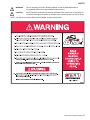
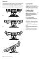
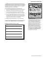
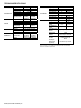
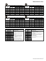
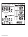
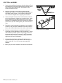
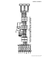
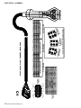
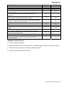
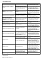
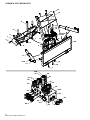
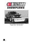
2005 Assembly & Operation Manual
Models: 810SS & 8611SS
A
64060 5/2/05
INTRODUCTIONS/TABLE OF CONTENTS
Congratulations on purchasing the most advanced, all-season skid steer snowplow available! The Blizzard Power
Plow® snowplow is clearing new trails for innovative design, rugged durability, quality craftsmanship and superior
performance. Our exclusive products are manufactured and tested in Michigan’s Upper Peninsula, the snow
capital of the Midwest. With an annual snowfall averaging over 250" we couldn’t imagine building snow removal
products anywhere else!
TABLE OF CONTENTS
Safety ............................................... 3
Operation .......................................... 4
Unpacking & Inspection .................... 5
Technical Specifications ................... 6
Torque Specifications ....................... 7
Moldboard Assembly ........................ 8
A-Frame Assembly ........................... 9
Electrical Assembly........................... 12
Mounting & Dismounting
Instructions ....................................... 19
Testing your Plow ............................. 20
Maintenance ..................................... 21
Troubleshooting ................................ 22
Moldboard & Wing Parts................... 24
A-Frame, Pivot Beam &
Manifold Parts................................... 26
Harnesses, Accessories & Kits......... 28
Warranty ........................................... 30
2
64060 (2005-810&8611SkidSteer).doc
SAFETY
WARNING
Prior to operating your Power Plow® snowplow, review the WARNING! label at
the passenger’s side rear of the moldboard (shown below).
CAUTION
NOTE: Read and understand all warnings indicated in this manual prior to operating the
snowplow. Warnings and cautions in the manual are indicated by the icons shown at left.
NOTE: If at any time the safety labels become illegible, promptly replace them.
3
64060 (2005-810&8611SkidSteer).doc
OPERATION
Your Blizzard Power Plow® snowplow is the most advanced and
versatile snowplow on the market. The easy-to-use controls
allow you to automatically adjust the plow blade and wings into
an infinite number of plowing positions. Review the illustrations
below to determine the best position for your plowing needs.
A. Compact Position
(8' or 8'-6" Blade Width)
• Primary position when transporting the
snowplow
• For use in heavy snow conditions with poor
visibility, initial clearing and tight quarters
• Ideal application: Residential driveways,
small roads
B. WidePass™ Position
A.
(10' or 11'-3" Blade Width)
• Primary position for clearing large surfaces
• For use in light snow conditions with good
visibility, final clearing and clean-up
• Ideal application: Large parking lots,
widening roadways
C. BucketBlade™ Position
(9'-3" or 9'-10" Blade Width)
• Primary position for transporting snow
• For use in initial clearing with decent
visibility, transporting large volumes of snow,
final clean-up
• Ideal application: Roadway intersections
D. WidePass™ Position Angled with
B.
C.
D.
4
64060 (2005-810&8611SkidSteer).doc
Wing Forward
• Primary position for accelerated angled
plowing
• For use in directional plowing, cornering,
diverting snow away from objects or
buildings
• Ideal application: Plowing adjacent to
buildings, driveway /road intersections
UNPACKING & INSPECTION
Your Blizzard Power Plow® snowplow has been packaged to
withstand transit and weather related damage. Fully inspect all
components upon receipt of your plow. In the event of shipping
damage or missing parts, immediately contact our Customer
Service Department at 1-888-680-8600.
Begin unpacking and inspection in the following order:
1. Remove the shipping document from the end panel of the
pallet wrap. Retain all documentation for your records.
2.
All wood framing and polyethylene material should be
removed from the pallet for easy access to the snowplow.
3.
Due to the odd shaped components and size of several
assembly parts, various cable ties and corrugated material
are used for scratch resistance and package orientation.
Please remove these items prior to assembly.
4.
Place the main blade assembly on a flat, level surface.
Once you have inspected all parts and removed all packaging
materials, your snowplow is ready to be fully assembled.
Retain this information for your records.
DATE OF PURCHASE:
DEALER/DISTRIBUTOR:
Pallet Wrap End Panel
The tear-resistant, woven polyethylene pallet
wrap contains a moisture barrier to help
protect all packaged components and keep
out the most inclement weather during
shipping and storage. The end panel of the
pallet cover contains important information
regarding the snowplow model and the
plow’s serial number. Both of these numbers
are given together. The first three (four)
digits of the number indicated is always the
plow model – 810 (or 8611) and the entire
number is the serial number (Ex: 810-00001
or 8611-00001). The shipping document is
also attached to the end panel. Be sure to
retain this list for your records.
DEALER PHONE NUMBER:
SNOWPLOW SERIAL NUMBER:
HYDRAULIC PUMP SERIAL NUMBER:
5
64060 (2005-810&8611SkidSteer).doc
TECHNICAL SPECIFICATIONS
PART
MOLDBOARD
SPECIFICATION
Length
Thickness
Height
Reinforcement
Cutting Edge
Finish
Trip Mechanism
WINGS
Length
Thickness
Height
Reinforcement
Cutting Edge
Finish
Material
A-FRAME
Cover
Finish
MANIFOLD
Construction
Valves
810
8611
96” (8’)
102” (8’6”)
12 gauge
11 gauge
31”
34”
4 ribs @ 1/4"
1/2” x 6”
5/8” x 6”
Powder Coat White
(4) 3/8”
(6) 3/8”
hooked
hooked
extension
extension
12”
23”
11 gauge
7 gauge
31”
34”
1 rib @ 1/4"
1/4” X 10”
3/8” X 12T1
1/2” T1
Powder Coat White
1/4” & 5/16” Mild Steel
1/4” Mild Steel w/ non-skid
texture
Powder Coat Black
Clear
Gold
Anodized
Anodized
Aluminum
Aluminum
Electro-hydraulic cartridge
PART
CYLINDERS
PLOW SPECS.
SPECIFICATION
Angle Cylinders
Stroke
Ram Diameter
Bore Diameter
Slide Box
Cylinders
Stroke
Ram Diameter
Bore Diameter
810
8611
2
10”
1-3/4”
2”
2”
2-1/4”
2
13-15/16”
1”
1-1/2”
Weight*
950 lbs.
Compact Width
WidePass™
Width
BucketBlade™
Width
Adjustable Plow
Shoes
Mount
Mechanism
Standard Control
Station
Integrated
Control
(Optional)
Anti-Trip
Mechanism
(Optional)
96” (8’)
120”
(10’)
18-7/16”
1-1/8”
1-3/4”
1470
Lbs.
102” (8’-6”)
132”
(11’-3”)
111”(9’-3”)
118”(9’-10”)
(2) Heavy-Duty Cast Steel
Universal Attachment
Plate
Pistol Grip w/ 3 switches
Auxiliary Harness w/
Diodes
One-Piece Trip-Lock bar
Blizzard Corporation reserves the right, under its Continuous Improvement Policy, to
change construction or design details and furnish equipment when so altered without
reference to illustrations or specifications.
6
64060 (2005-810&8611SkidSteer).doc
TORQUE SPECIFICATIONS
Grade Identification Marking for J429-Grade 5 Bolt
SAE J429 – Grade 5
Clamp Loads
Tightening Torque
(lbs)
“Lubricated”
“Dry”
1/4-20
2,000
6 ft-lbs
8 ft-lbs
5/16-18
3,350
13 ft-lbs
18 ft-lbs
3/8-16
4,950
23 ft-lbs
31 ft-lbs
7/16-14
6,800
37 ft-lbs
50 ft-lbs
1/2-13
9,050
57 ft-lbs
75 ft-lbs
9/16-12
11,600
82 ft-lbs
109 ft-lbs
5/8-11
14,500
113 ft-lbs
151 ft-lbs
3/4-10
21,300
200 ft-lbs
266 ft-lbs
7/8-9
29,435
321 ft-lbs
430 ft-lbs
1-8
38,600
482 ft-lbs
640 ft-lbs
Nominal
Thread Size
Grade Identification Marking for Metric-Grade 8.8 Bolt
Metric Class 8.8
Diameter
Clamp Loads
Tightening Torque
(mm)
(Pounds)
“Lubricated”
“Dry”
5
1,389
3 ft-lbs
5 ft-lbs
6
1,965
6 ft-lbs
8 ft-lbs
7
2,826
10 ft-lbs
13 ft-lbs
8
3,579
14 ft-lbs
19 ft-lbs
10
5,672
28 ft-lbs
37 ft-lbs
12
8,243
49 ft-lbs
65 ft-lbs
14
11,246
77 ft-lbs
103 ft-lbs
16
15,882
125 ft-lbs
167 ft-lbs
18
19,423
172 ft-lbs
229 ft-lbs
20
24,784
244 ft-lbs
325 ft-lbs
Turns
Size
N/A
N/A
2
2
1-1/2
1-1/2
1-1/2
1-1/4
1
1
1
1
1
-02
-03
-04
-05
-06
-08
-10
-12
-14
-16
-20
-24
-32
37° JIC Flare Torque Values
Ft-lbs
Assembly steps
min.max
1. Make sure the tubing and threads are
6-7
clean.
8-9
2. Lubricate the threads with 10W hydraulic
oil.
11-12
3. Hand tighten the nut/sleeve to approx. 30
14-15
in-lbs.
18-20
4. Make alignment marks on the nut and
fitting.
36-39
5. Tighten to turn or torque specification.
57-63
6. When fully tightened, make a 2nd set of
alignment marks at the fully tighten
79-88
positioned.
94-103
108-113
NOTE: Torque values specified are for
threads lubricated with 10W hydraulic oil.
127-133
158-167
Over tightening will reduce the clamping force
resulting in loss of seal and reduction of flow.
245-258
Grade Identification Marking for J429-Grade 8 Bolt
SAE J429 – Grade 8
Tightening Torque
Clamp Loads
(lbs)
“Lubricated”
“Dry”
1/4-20
2,850
9 ft-lbs
12 ft-lbs
5/16-18
4,700
18 ft-lbs
25 ft-lbs
3/8-16
6,950
32 ft-lbs
44 ft-lbs
7/16-14
9,600
53 ft-lbs
70 ft-lbs
1/2-13
12,800
80 ft-lbs
107 ft-lbs
9/16-12
16,400
115 ft-lbs
154 ft-lbs
5/8-11
20,300
159 ft-lbs
211 ft-lbs
3/4-10
30,100
282 ft-lbs
376 ft-lbs
7/8-9
41,550
454 ft-lbs
606 ft-lbs
1-8
54,540
680 ft-lbs
900 ft-lbs
Nominal
Thread Size
Grade Identification Marking for Metric-Grade 10.9 Bolt
Metric Class 10.9
Diameter
Tightening Torque
Clamp Loads
(mm)
(Pounds)
“Lubricated”
“Dry”
5
1,987
5 ft-lbs
7 ft-lbs
6
2,812
8 ft-lbs
11 ft-lbs
7
4,044
14 ft-lbs
19 ft-lbs
8
5,121
20 ft-lbs
27 ft-lbs
10
8,116
40 ft-lbs
53 ft-lbs
12
11,796
70 ft-lbs
92 ft-lbs
14
16,092
111 ft-lbs
148 ft-lbs
16
21,970
173 ft-lbs
231 ft-lbs
18
26,868
238 ft-lbs
317 ft-lbs
20
34,284
338 ft-lbs
450 ft-lbs
Size
-02
-03
-04
-05
-06
-08
-10
-12
-14
-16
-20
-24
-32
O-Ring Boss Torque Values
Ft-lbs
Assembly steps
min.max
1. Verify the port, o-ring, sealing surfaces and threads
6-7
are clean and free of damage.
8-10
2. Lubricate the threads and the o-ring with 10W
hydraulic oil.
13-15
3. For an adjustable O.R.B., completely back off the lock
17-21
nut and washer.
22-25
4. Hand tighten the fitting until it contacts the port
spotface. Point the elbow or tee in the desired
40-43
direction and hold.
43-57
5. Torque to specification.
68-75
NOTE: Torque values specified are for threads lubricated
90-99
with 10W hydraulic oil.
112-123
146-200
154-215
218-290
7
64060 (2005-810&8611SkidSteer).doc
MOLDBOARD ASSEMBLY
1.
60005
Remove dust cap from both of the slide box cylinders
located at the center/rear of the moldboard. Attach adapters
(60007 on the 810SS and 60272 on the 8611SS) to each of
the base ports and rod ports.
9
16
9
16
60007
NOTE: All of the hydraulic adapters can be found packaged with
the manifold assembly.
2.
Connect hoses (60224) to each of the hydraulic adapters on
the cylinders. NOTE: Review the label on each hose for the
appropriate part number
3.
Position the pivot beam and A-frame, near the mount
locations at the rear of the blade. Place the slide box cylinder
hydraulic hoses through the rubber grommet openings on
each side of the front face of the pivot beam.
4.
Position the pivot beam between the two support ribs until
the connecting points on the beam align with those on the
plow. Insert clevis pin (50069) through each mounting hole
and secure with cotter pins (61357).
5.
Hook each extension spring to the receiving holes on the
pivot beam and attach the opposite end of the spring to its
respective spade bolts. Install the spade bolts through the
extension spring mounting angle on the top rear of the blade.
Secure spade bolts with a 5/8" flat washer and a 5/8"-11
nylock nut. Tighten each nut until a piece of paper can pass
between the 3rd & 4th coils on the spring.
6.
Install the blade guides at each end of the moldboard. Insert
the capscrew through the holes at the top of the wing
reinforcement rib. Tighten all screws with lock nuts.
7.
Assemble the A-Frame.
8
64060 (2005-810&8611SkidSteer).doc
9
16
9
16
9
16
60272
9
16
Skid Steer Adapters
Feed each group of hoses, 2 per side,
through the grommets in the pivot beam.
Positioning the hoses through the pivot
beam supports the hoses while in use and
prevents them from dragging on the ground.
A-FRAME ASSEMBLY
1.
The manifold and angle cylinders have been secured to the
A-Frame at the factory; however, each contains several
components that you will need to install.
2.
Remove the A-Frame cover to gain access to the manifold.
3.
Each of the hose ports on the manifold are covered with
stretch wrap. Remove the wrap and install adapter (60272)
to ports #1, 2, 7, 8, 9 & 10.
NOTE: DO NOT let any foreign objects enter into the open ports.
The valves can become contaminated and greatly hinder the
plow’s performance. Torque to proper specifications.
S9
S1
S5
CV5
7
2
10
8
1
9
CV4
CV2
PC
Ports #1, 2, 7, 8, 9 &10.
NOTE: All ports are identified by a stamped number on the
manifold. The numbers also identify the hydraulic functions,
which can be referenced on the label under the manifold cover.
4.
Route the hydraulic hose groupings from the pivot beam to
the access holes located on the sides of the a-frame.
Connect the hoses to their respective adapters on the
manifold.
CAUTION: When handling the manifold, hold the
manifold at the sides of the block. Never handle the
manifold by coils. Doing so can cause a solenoid
cartridge to bend, causing the cartridge to stick when
activated.
5.
Remove the dust cap from both of the hydraulic angle
cylinder ports and attach a 90° adjustable elbow adapter
(60005) to each port. Each adapter should be angled toward
the top of the moldboard. Connect one 3/8" x 26" (60223 or
60224 36" for 8611) hydraulic hose to each angle cylinder
adapter. Be careful not to over tighten the hose
connections. NOTE: The cylinder ports should be facing
away from the A-frame. NOTE: The 810SS & 8611SS Aframe are the same but use different mounting points for the
angle cylinders due to different stroke length on the
cylinders. Use caution when replacing.
6.
Connect the hoses to their respective adapters on the
manifold.
7.
Install adapters (60089) to ports “P” & “T” on the manifold.
Connect hydraulic hose (60086) to adapters. Be careful not
to over tighten the hose connections.
8.
Install the wire harness.
T
P
Ports “T” & “P”.
8611SS USES
OUTER HOLES
810SS USES
INNER HOLES
Angle Cylinder Mounting
9
64060 (2005-810&8611SkidSteer).doc
HYDRAULIC GUIDE
10
64060 (2005-810&8611SkidSteer).doc
SCHEMATIC
A
B
C
D
E
F
G
H
J
K
S5
S4
S3
S9
S10
S1
S2
S10
S4
(BOTTOM)
S2
S3
(TOP)
S1
S9
S5
ELECTRICAL SCHEMATIC
LEFT SLIDE BOX
RIGHT SLIDE BOX
RIGHT ANGLE
8
RV1
1700 PSI
(2800 PSI)
1
7
RV2
1500 PSI
(2650 PSI)
CV1
50 PSI
LEFT ANGLE
2
9
3000 PSI
RV5
RV4
1700 PSI
(2800 PSI)
CV2
50 PSI
10
RV3
1500 PSI
(2650 PSI)
CV3
50 PSI
CV4
50 PSI
S2
S1
S3 S4
S10
S9
S5
CV5
5 PSI
PC
50 PSI
P
T
HYDRAULIC SCHEMATIC
NOTE: Where applicable, Model 8611SS values are in parenthesis.
11
64060 (2005-810&8611SkidSteer).doc
ELECTRICAL-ASSEMBLY
1.
Connect the manifold coil harness to the plow harness. Feed
the opposite end of the plow harness through the top access
hole in the A-frame (same as 3/4" tank hydraulic hose)
located on the driver’s side.
2.
Attach the grounds on the coil wire harness and plow
harness with a 3/8"-16 x 1-1/2" hex cap screw and 3/8" tooth
lock washer to the A-frame. Secure the wires with a lock
nut. Review the diagram for the proper ground location.
3.
Connect the plow harness to the vehicle harness, and then
the vehicle harness to the pistol grip control harness. Attach
the ground wire from the vehicle harness to the cab of the
skid steer. The pink/black power wire connects to a switched
power source (on and off with ignition) with a minimum of 12
volts.
4.
Position the vehicle harness mount bracket in an accessible
location for easy on-and-off installation inside the skid steer.
Secure the vehicle side harness in the notch on the bracket.
GROUND
MOUNT
HOLE
MANIFOLD
MOUNT HOLES
Control Mount Bracket (70048)
5.
Position the control harness mount bracket vertically or
horizontally for user preference inside the skid steer. Secure
with hardware provided. Position the pistol grip control into
the bracket and “twist-lock” it into place. NOTE: Install the
bracket so it does not interfere with any safety devices that
might rotate in front of the operator.
6.
Complete the assembly by attaching the A-frame cover.
Align the holes in the cover with those on the A-frame and
secure it with 3/8"-16 x 1-1/2" hex cap screws and 3/8"
washers.
7.
Mount your plow to the skid steer, and then test all functions.
12
64060 (2005-810&8611SkidSteer).doc
CONTROL SCHEMATIC
BLUE/BLACK
BLUE/WHITE
BLUE/BLACK
BLUE/WHITE
9
BLUE/BLACK
BLUE/WHITE
BROWN
A
H
G
A
RED
RED
RED
RED
RED
GROUND
DUMP SOLENOID
GROUND
L. RETRACT
GROUND
L. EXTEND
GROUND
R. ANGLE
A
RED
B
RED
A
GROUND
R. RETRACT
B
K
F
C4 J
E
G
C3
H
E
J
F
K
D
A
14
GREEN
BLUE
RED/BLACK
RED/WHITE
BLACK
B
9
3
14
3
8
13
4
13
1
4
8
1
B
A
GROUND
L. ANGLE
A
G
GREEN
BLUE
RED/BLACK
RED/WHITE
BLACK
M1 M2
SS PISTOL GRIP CONTROL HARNESS SCHEMATIC (62131);
INCLUDES 62132, 62133, 62134, 62135, 62136, 62210, 62211&
62219
H
K
F
C2 J
E
G
C1
H
E
J
K
C
D
F
C
D
A
BLACK
B
A
GROUND
R. EXTEND
B
GREEN
BLUE
RED/BLACK
RED/WHITE
BLACK
BLACK
PINK/BLACK
A
12V
+
A
LEFT BOX RETRACT
POWER
LEFT BOX EXTEND
SWITCH #3
2
4
6
RIGHT ANGLE
POWER
LEFT ANGLE
SWITCH #2
2
4
6
RIGHT BOX RETRACT
POWER
RIGHT BOX EXTEND
SWITCH #1
2
4
6
BLACK
PINK/BLACK
CUSTOMER
SUPPLIED
S5
S9
S10
S4
S1
S3
S2
13
64060 (2005-810&8611SkidSteer).doc
B
ELECTRICAL- ASSEMBLY
CONTROL
PIN #
1
2
3
4
5
6
IEW
K V H #1
C
18
6"
84"
1 2
3 4
5 6
TOP
1 2
3 4
5 6
GREEN
18
18
6"
84"
AWGLENGTH
PINK/BLACK
18
84"
BLUE
COLOR
NOTE: NO NUMBERS ON SWITCH
(USE THIS CHART TO FIND TOP)
SWITCH # 2
TOP
BACK VIEW
OF SWITCH #2
PIN #
1
2
3
4
5
6
BAC
OF S K VIEW
WITC
H #3
BACK VIEW OF SKID STEER SWITCH PLATE
AC
B
IT
P
SW
TO
OF
1 2
5 6
3 4
SWITCH # 1
NOTE: NO NUMBERS ON SWITCH
(USE THIS CHART TO FIND TOP)
18
AWGLENGTH
RED/BLACK
COLOR
PINK/BLACK
18
84"
RED/WHITE
PIN #
1
2
3
4
5
6
PIN #
A
B
C
D
E
F
G
H
J
K
COLOR
PINK/BLACK
N/A
BLACK
BLACK
GREEN
BLUE
BLUE/BLACK
BLUE/WHITE
RED/BLACK
RED/WHITE
SWITCH # 3
NOTE: NO NUMBERS ON SWITCH
(USE THIS CHART TO FIND TOP)
18
6"
84"
AWGLENGTH
18
COLOR
PINK/BLACK
BLUE/BLACK
18
84"
BLUE/WHITE
SS CONTROL HARNESS (62210, 62211& 62219)
G
B
H
C
FUNCTION
POWER
N/A
GROUND (JUMPER)
GROUND (JUMPER)
RIGHT ANGLE
LEFT ANGLE
LEFT BOX RETRACT
LEFT BOX EXTEND
RIGHT BOX RETRACT
RIGHT BOX EXTEND
A
END VIEW
LOOKING AT
CONNECTOR
F
K
E
AWG
18
N/A (JUMPER)
18
18
18
18
18
18
18
18
D
J
C1
14
64060 (2005-810&8611SkidSteer).doc
ELECTRICAL ASSEMBLY
E
D
END VIEW
LOOKING AT
CONNECTOR
COLOR
J
PIN #
PINK/BLACK
N/A
BLACK
BLACK
GREEN
BLUE
BLUE/BLACK
BLUE/WHITE
RED/BLACK
RED/WHITE
K
A
B
C
D
E
F
G
H
J
K
C
H
C2
B
A
F
G
FUNCTION
POWER (POS)
N/A
GROUND (NEG)
GROUND
RIGHT ANGLE
LEFT ANGLE
LEFT BOX RETRACT
LEFT BOX EXTEND
RIGHT BOX RETRACT
RIGHT BOX EXTEND
AWG
18
N/A
18
18
18
18
18
18
18
18
END VIEW
LOOKING AT
CONNECTOR
SS VEHICLE HARNESS (62132, 62133)
M1
1
PIN #
2
3
4
5
6
7
8
9
10
11
12
13
14
FUNCTION
GROUND
N/A
N/A
N/A
RIGHT ANGLE
LEFT ANGLE
N/A
N/A
N/A
RIGHT BOX RETRACT
LEFT BOX RETRACT
N/A
N/A
N/A
RIGHT BOX EXTEND
LEFT BOX EXTEND
BLIZZARD PLUG (SQUARE)
COLOR
BLACK
N/A
N/A
N/A
GREEN
BLUE
N/A
N/A
N/A
RED/BLACK
BLUE/BLACK
N/A
N/A
N/A
RED/WHITE
BLUE/WHITE
AWG
18
N/A
N/A
N/A
18
18
N/A
N/A
N/A
18
18
N/A
N/A
N/A
18
18
NOTE: REMOVE EXCESS RUBBER
FROM TERMINALS NOT USED
END VIEW
LOOKING AT
CONNECTOR
15
64060 (2005-810&8611SkidSteer).doc
ELECTRICAL- ASSEMBLY
PIN #
1
2
3
4
5
6
7
8
9
10
11
12
13
14
M2
END VIEW
LOOKING AT
CONNECTOR
GROUND
N/A
N/A
N/A
RIGHT ANGLE
LEFT ANGLE
N/A
N/A
N/A
RIGHT BOX RETRACT
N/A
PUMP SOLENOID
N/A
N/A
RIGHT BOX EXTEND
LEFT BOX EXTEND
FUNCTION
18
N/A
N/A
N/A
18
18
N/A
N/A
N/A
18
N/A
18
N/A
N/A
18
18
AWG
BLIZZARD PLUG (SQUARE)
COLOR
BLACK
N/A
N/A
N/A
GREEN
BLUE
N/A
N/A
N/A
RED/BLACK
N/A
BROWN
N/A
N/A
RED/WHITE
BLUE/WHITE
SS PLOW HARNESS (62134, 62135)
END VIEW
LOOKING AT
CONNECTOR
A
B
C
D
E
F
G
H
J
K
PIN #
BROWN
N/A
N/A
BLACK
GREEN
BLUE
BLUE/BLACK
BLUE/WHITE
RED/BLACK
RED/WHITE
COLOR
C3
D
FUNCTION
H
C
A
F
G
B
DUMP SOLENOID
N/A
N/A
GROUND
RIGHT ANGLE
LEFT ANGLE
LEFT WING RETRACT
LEFT WING EXTEND
RIGHT WING RETRACT
RIGHT WING EXTEND
E
J
END VIEW
LOOKING AT
CONNECTOR
K
AWG
18
N/A
N/A
18
18
18
18
18
18
18
16
64060 (2005-810&8611SkidSteer).doc
ELECTRICAL-ASSEMBLY-COIL HARNESS
SS COIL HARNESS (62136)
17
64060 (2005-810&8611SkidSteer).doc
AUXILIARY CONTROL HARNESS W/ DIODES (OPTIONAL)
A
F
B
G
C
COLOR
H
PIN #
N/A
N/A
N/A
BLACK
GREEN
BLUE
BLUE/BLACK
BLUE/WHITE
RED/BLACK
RED/WHITE
C4
A
B
C
D
E
F
G
H
J
K
C4
D
J
E
K
FUNCTION
N/A
N/A
N/A
GROUND (JUMPER)
RIGHT ANGLE
LEFT ANGLE
LEFT BOX RETRACT
LEFT BOX EXTEND
RIGHT BOX RETRACT
RIGHT BOX EXTEND
C4
BLACK
RED/WHITE
RED/BLACK
BLUE/WHITE
BLUE/BLACK
BLUE
GREEN
AUXILIARY CONTROL
HARNESS W/ DIODES
(62166)
AWG
N/A
N/A
N/A
18
18
18
18
18
18
18
PIN #
COLOR
D4
N/A
BROWN
N/A
BLACK
GREEN
BLUE
BLUE/BLACK
BLUE/WHITE
RED/BLACK
RED/WHITE
D2
D3
D5
D6
A
B
C
D
E
F
G
H
J
K
D1
SP-2
SP-4
SP-3
SP-7
SP-6
SP-5
C3-2
FUNCTION
N/A
PUMP SOLENOID
N/A
GROUND
RIGHT ANGLE
LEFT ANGLE
LEFT BOX RETRACT
LEFT BOX EXTEND
RIGHT BOX RETRACT
RIGHT BOX EXTEND
BROWN - PIN B
GREEN - PIN E
BLUE - PIN F
BLUE/BLACK - PIN G
BLUE/WHITE - PIN H
RED/BLACK - PIN J
RED/WHITE - PIN K
BLACK - PIN D
AWG
N/A
18
N/A
18
18
18
18
18
18
18
C3-2
E
K
D
J
C
H
B
G
A
F
C3-2
18
64060 (2005-810&8611SkidSteer).doc
MOUNTING & DISMOUNTING INSTRUCTIONS
Prior to operating your Power Plow® snowplow, review the Mounting and Dismounting Instructions label on the
back of the driver’s side moldboard.
NOTE: If at any time the Mounting and Dismounting Instructions label, or any other label attached to your
snowplow become illegible, promptly replace them.
19
64060 (2005-810&8611SkidSteer).doc
TESTING
1. To test all of the functions on the Power Plow, your
snowplow needs to be properly attached to the skid steer.
Refer to the Mounting & Dismounting label on the back of
the plow.
2. Complete the hydraulic connections with the skid steer
turned off. Note: Due to the various make and model skid
steer available, hydraulic couplings for the auxiliary hydraulic
connections are not provided. Consult your skidsteer’s
Operation Manual for the appropriate couplings needed.
Connect the couplings to the hoses for the pressure port
(“P”) and the tank port (“T”)on the manifold. Complete the
hydraulic installation by making the appropriate connections
at the skid steer.
WARNING: Always use caution when connecting
high-pressure hydraulic fittings. Hydraulic fluid
under pressure can puncture skin causing serious
injury or death. In the event of a hydraulic leak,
relieve hydraulic pressure before loosening fittings.
If injured, seek emergency medical help
immediately.
3. Start the skid steer and begin to initiate the Power Plow’s
blade functions. Note: Depending on the skid steer model, it
may be necessary to turn on the skid steer’s auxiliary
hydraulic switch prior to operating the plow. The left switch
operates the driver’s side wing. Push the switch “up” to
extend the wing and “down” to retract the wing. Push the
center switch “up” to angle left and “down” to angle right.
The right switch operates the passenger’s side wing and
works the same as the left switch. Upon initiating the
switches on the pistol grip control, you may notice a plow
function is slow or delayed. The hydraulic fluid is filling the
cylinders and replacing air in the system. Monitor the
hydraulic fluid level in your skid steer, and fill as necessary.
20
64060 (2005-810&8611SkidSteer).doc
MAINTENANCE
MAINTENANCE
Check fasteners for tightness. Torque to specifications.
Check hoses for wear and leaks.
Check cylinders for leaks; inspect rod ends for corrosion & pitting
Lubricate all exposed cylinder rod ends with liquid white lithium grease to
prevent corrosion.
Check cutting edges and plow shoes for wear. NOTE: Do not discard
plow shoe washers, these should be retained for different shoe
adjustments.
Clean and lubricate all electrical plugs and connections with dielectric
grease. Clean and install all dust caps prior to storing.
Lubricate all pins and bushings, inner slide box and A-frame latch with
NLGI Grade 2 multi-purpose lithium complex grease with molybdenum
(MPGM) ) to maintain consistent operation
Clean and paint all scratches or exposed metal with Blizzard touch-up
paint
Check the hydraulic oil level. Never mix different types of fluid.
Change the hydraulic fluid as specified in your Skid Steer owner’s
manual.
Check the trip spring adjustment. Properly adjusted tension will allow a
sheet of paper to pass between the 3rd and 4th coils of the spring.
Adjust the wing spring as needed or install an optional second extension
spring for increased return speed.
Pressure wash and dry the entire snowplow prior to storing
Cover the snowplow with a tarp if stored outside. This will protect your
plow from sun fading and inclement weather which can lead to
accelerated corrosion.
PERIODICALLY
X
X
X
YEARLY
X
X
X
X
X
X
X
X
X
X
X
X
X
X
REMOVING FROM STORAGE
1. Perform all regular maintenance.
2. Replace the hydraulic fluid in the hydraulic system. Prolonged storage could result in condensation build-up.
3. Follow the mounting procedure on the Mounting & Dismounting label.
4. Initiate all of the functions & test before using.
21
64060 (2005-810&8611SkidSteer).doc
TROUBLESHOOTING
PROBLEM
CAUSE
S5 coil is not magnetizing.
Plow functions will not work after all
connections are made or plow functions
are slow.
Solenoid cartridge valve may be
contaminated or damaged. A bent or
over torqued cartridge will not allow the
valve to move freely inside of the
cartridge.
SOLUTION
S5 coil should magnetize with each
function.
Determine a damaged cartridge valve
by reversing the driver’s side and
passenger’s side cartridge valves one at
a time. Replace valve if necessary.
For plow functions to work, the skid
steer hydraulic fluid flow should be set
Plow functions start and terminate
Skid steer hydraulic fluid flow is set to
to continuous flow. Review your skid
suddenly.
variable flow.
steer operation manual for proper flow
settings.
Diodes may be corroded or damaged.
Clean diodes thoroughly and/or replace.
Verify harness is not damaged. Review
Multiple valves function simultaneously.
schematic(s) to troubleshoot
Wire harness may be damaged.
connection(s). Replace if needed.
Review the Hydraulic Valve &Hose Port
Plow functions are reversed (i.e.
Identification Guide under the A-frame
Driver’s side wing extends when
Hydraulic hoses are connected wrong
cover for proper port locations and/or
passenger’s side wing is activated from
or coils and wiring are incorrect.
place respective coils over correct
the control.)
valves.
Pressure (P) and tank (T) hoses are
Review the skid steer operation manual
Both wings extend when the skid steer
installed in the wrong position on the
to determine the pressure and tank
hydraulics are turned on.
skid steer.
connections.
Using a jumper wire, connect pin K to
Skid steer computer conflicts with
pin L at the back of the cylindrical
Plow angles only one way.
cylindrical connection.
connector (cylindrical connector only).
Test the wing pressure relief. Attach a
T-fitting with a fluid PSI gauge to the
base end of the wing cylinder. Pressure
The wing pressure relief valve is
relief should not be greater than
Wing will not stay angled when plowing.
contaminated.
1700PSI (2800PSI for 8611SS) Replace
if less than 1500-1700PSI (26002800PSI).
Follow the guidelines indicated above;
The angle pressure relief valve is set
however, the PSI setting should not
too low. NOTE: Increasing the pressure
exceed 3000PSI. NOTE: If the plow is
Plow will not stay angled when plowing.
relief valve will cause damage to your
floating back when angled to the right,
plow. Do not set the pressure relief
adjust the left pressure relief valve and
greater than 3000PSI.
vice versa.
Verify control station, harness and all
Control station, harness or cables may
cables are securely connected. Clean if
be loose or improperly connected.
necessary.
Verify S9 &S10 coils (passenger’s side
slide box retract and extend) and S1
Wing will not move.
&S2 (driver’s side slide box retract and
extend) are connected properly.
No power to the cartridge valve.
Diagnose the wire harness. Review all
wire harness schematics. If power is
present, review the next step.
Verify coils are magnetizing. Position a
screwdriver inside of the coil. When the
respective function is activated, the
screwdriver is drawn to the side of the
Wing will not move.
Coils are receiving power.
coil. If the coil is not drawn to the
screwdriver, replace the coil. If power is
present, review the next step.
Solenoid cartridge may be
Determine a damaged cartridge valve
contaminated or damaged. A bent
by reversing the driver’s side and
cartridge will not allow the valve to
passenger’s side cartridge valves.
move freely inside of the cartridge.
Replace valve if necessary.
NOTE: Verify coils S3 & S4 for angle
Plow will not angle.
Review all probable causes above.
functions.
Should your snowplow develop other problems not indicated, contact your local Dealer for technical assistance and/or
replacement parts.
22
64060 (2005-810&8611SkidSteer).doc
NOTES
23
64060 (2005-810&8611SkidSteer).doc
MOLDBOARD & WING PARTS
5
6
38
42
1
2
3
45
44
41
4
9
43
8
15
10
12
11
16
18
17
19
14
13
25
26/27
24
27/28
22
21
20A
23
13A
35
38
39
33
20
34
36
30
37
40
24
64060 (2005-810&8611SkidSteer).doc
7
32
29
31/32
MOLDBOARD & WING PARTS
REF
PART NUMBER
QUANTITY
810SS 8611SS
1
1
1
1
1
1
1
1
1
1
7
7
13
6
7
1
1
1
1
1
1
1
1
2
2
2
2
2
2
36
36
2
2
1
1
4
4
4
4
4
4
2
2
4
4
4
4
1
1
1
1
1
1
2
2
2
2
2
2
1
1
2
2
2
4
8
2
2
2
2
2
2
2
2
2
2
8
4
4
4
4
2
2
40
41
52074
52085
61170
63160
61171
61292
52139
61196
61623
61365
61626
51042
51100
61083
63065
51048
51069
50057
50075
63113
61220
61102
61101
61103
63063
61383
11871
61384
61049
61051
61052
51043
51101
61084
63064
51047
51070
61418
61360
61419
61361
61362
50058
50074
61416
61398
61099
61385
61028
51009
13307
61425
60347
60207
61063
60007
60272
60224
61198
42
11989
2
2
43
44
45
61030
61187
61064
2
4
4
2
6
6
1
2
3
4
5
6
7
8
9
10
11
12
13A
13
14
15
16
17
18
19
20A
20
21
22
23
24
25
26
27
28
29
30
31
32
33
34
35
36
37
38
39
DESCRIPTION
Moldboard Weldment
Label, WARNING! (Blz1013)
Decal, Center Moldboard (Blz1070)
Label, Skid Steer Mounting & Dismounting (Blz1014)
Cutting Edge, Moldboard (1080)
Bolt, 1/2"-13 x 1-1/2" Carriage Gr8
Bolt, 5/8-11 UNC x 2" Carriage Gr8
Nut, 1/2"-13 Flanged Lock Z
Nut, 5/8"-11 Flanged Lock Z
Wing Weldment, Driver’s Side
Decal, Wing, Driver’s Side
Cutting Edge, Weldment Driver’s Wing (T1)
Slide Box, Weldment Drivers
Label, Warning! Multiple Pinch Points (Blz1068)
Plow Shoe Asm, Heavy-Duty Cast Iron (8-3/8" Shaft) Includes Ref 13-15
Spacer, 1-1/8" I.D., 1-5/8" O.D. x 1-1/2" YZ
Washer, 1" Flat YZ
Pin, 7/16" x 1-3/4" Linch YZ
Label, Serial Number, Sequentially Numbered (Blz1049)
Screw, 5/16"-18 x 2-1/4" HHCS Gr8 YZ
Pin, 1" Dia. x 4-3/4"Slide Box Stop (with 3/8" Dia. hole)
Nut, 5/16"-18 Top Lock Z
Plow Guide Assembly Includes Ref 20-21
Screw, 5/16"-18 x 1" HHCS Gr5 Z
Nut, 5/16"-18 Nylock Z
Wing Weldment, Passenger’s Side
Decal, Wing, Passenger’s Side
Cutting Edge, Weldment Passenger’s Wing (T1)
Bolt, 1/2"-13 x 3-1/2" Carriage Gr8 P
Bolt, 1/2"-13 x 5" Carriage Gr8 P
Bolt, 1/2"-13 x 4-1/2" Carriage Gr8 P
Bolt, 1/2"-13 x 5-1/2" Carriage Gr8 P
Bolt, 1/2"-13 x 6-1/2" Carriage Gr8 P
Slide Box, Weldment Passenger
Bolt, 5/8"-11 x 7-3/8" Spade Gr8 Z
Spring, 13" O.A.L. x 2" O.D. x 5/16" Extension
Spring, 15-1/4" O.A.L. x 2-3/8" O.D. x 3/8" Extension
Pin, 5/8" Dia. x 3" Clevis YZ
Pin, 1/4" Dia. x 1-1/4" Spring
Pin, 3/4" Dia. x 9" Wing/Slide Box Pivot
Pin, 1" Dia. x 11-1/8" Wing/Slide Box Pivot
Plug, 2-51/64" O.D., 2-9/32" I.D. x 1/2" Black Polyethylene
Hydraulic Cylinder, Slide Box Extend/Retract
Nut, 5/8"-11 Top Lock Z
Hydraulic Adapter, 9/16"-18 x 9/16"-18 Male O.R.B.
Hydraulic Adapter, 9/16"-18 x 9/16"-18 45° Adjustable Elbow O.R.B.
Hydraulic Hose, 3/8" x 36" (Ports #7, 8, 9 & 10) Slide Box Extend/Retract
Cap, 5/8" I.D., 3/4" O.D. x 1" Black Vinyl
Pin, 5/8" Dia. x 11-1/2" Hydraulic Cylinder Base End (with 1/4" Dia. hole) - Slide Box
Extend/Retract
Pin, 1/8" Dia. x 2-5/8" Hair Cotter Z
Bolt, 5/8"-11 x 6-3/8" Spade Gr8 Z
Washer, 5/8" SAE Hardened YZ
25
64060 (2005-810&8611SkidSteer).doc
A-FRAME & PIVOT BEAM PARTS
14
13
15
12
5
16
15
10
4
10
1
SEE VIEW
BELOW
2
17
19
7
3
18
22
6
2
20
4
8
2
9/10
21
11
15
21
35A
34
35
36
33
32
37
31
33
38
23A
30
23
24
29
26
64060 (2005-810&8611SkidSteer).doc
28
27
26
25
A-FRAME & PIVOT BEAM PARTS
REF
PART NUMBER
QUANTITY
810SS 8611SS
1
1
6
6
2
2
4
4
1
1
1
1
4
4
2
2
2
4
6
2
2
1
1
1
1
7
7
11
11
2
2
1
1
1
1
2
2
1
1
3
3
7
7
1
1
1
1
2
2
1
1
1
1
1
1
4
4
6
6
2
2
1
1
5
5
4
4
5
5
31
32
33
34
41041
41052
61357
50069
41051
61331
61008
61217
60029
60324
60223
60224
60005
70143
70134
61214
61016
61514
61328
61307
60086
70132
61034
61275
60341
60342
60354
60355
60089
60320
60356
60183
60225
60272
60279
60227
60168
62163
60166
60052
35A
62161
1
1
35
36
60321
62164
60278
60226
60049
60322
1
2
2
2
2
1
2
2
2
2
1
2
3
4
5
6
7
8
9
10
11
12
13
14
15
16
17
18
19
20
21
22
23A
23
24
25
26
27
28
29
30
37
38
-
DESCRIPTION
Pivot Beam Weldment
Pin, Cotter, 1/4" x 1-1/2" Z
Pin, 3/4"Dia. x 3" Clevis YZ
Pin, 3/4"Dia. x 5" Clevis YZ
Screw, 1"-8 x 9" HHCS Gr8 P
Nut, 1"-8 Top Lock Z
Grommet, 1-1/2" I.D., 2-1/8" O.D. Black Rubber, 60 Durometer
Hydraulic Cylinder, Plow Angle
Hydraulic Hose, 3/8" x 26" Plow Angle
Hydraulic Hose, 3/8" x 36" Plow Angle
Hydraulic Adapter, 9/16"-18 x 9/16"-18 90° Adjustable Elbow O.R.B.
Mat, A-Frame Rubber
Plate, A-Frame Cover
Screw, 3/8-16 UNC x 1-1/4” HHCS
Washer, 3/8” SAE Hardened
Screw, 3/8-16 UNC x 4 HHCS
Screw, 3/8-16 UNC x 1-1/2” HHCS
Washer, 3/8” Internal/External Tooth Lock
Hydraulic Hose, 3/4"x78" -str./str.
A-frame Weldment
Nut, 3/8-16 UNC Hex Nylock
U-Nut, 3/8-16 UNC
Manifold Assembly
Manifold Block (with Cross Port Relief), Clear Anodized Aluminum
Manifold Block (with Cross Port Relief), Gold Anodized Aluminum
Hydraulic Adapter, 1 1/16-12 x 1 1/16-12 Male O.R.B. connector
Valve, Spool Two-Way N.O.
Valve, Back Pressure Check 5PSI
Valve, Pressure Compensation Regulation
Valve, Check, 50 PSI
Hydraulic Adapter, 9/16-18 x 9/16-18 Adj. Elbow
Valve, Relief, 1500PSI
Valve, Relief, 2650 PSI
Valve, Relief, 3000 PSI
Coil, PDL 12 VDC
Valve, Spool, Three-Way, Two Position
Nut, 1/2-20 Hex Jam, YZ
Coil Harness Assembly
Includes 62045 (1), 62118 (2), 62116 (5), 62096 (7), 62097 (7), Ref 32 & 36
Valve, Four Way-Three Position Spool
Coil, LDL 12 VDC
Valve, Relief 1700 PSI
Valve, Relief 2800 PSI
Plug , SAE Hollow Hex O.R.B.
Piston Assembly
27
64060 (2005-810&8611SkidSteer).doc
HARNESSES, ACCESSORIES & KITS
2
1A
3
1
7
6
5
4
5A
8
11. Beef-up your Power Plow
snowplow with our 3/8" thick wing
cutting edges. These edges are
built to withstand heavy plow use
on the roughest road surfaces and
also provide added material for
protection against sidewalk curb
wear. Mounting hardware included.
14. Putting your snowplow away for
the winter? Have a deep scratch to
cover? Clean up your blade and
plow parts with our gloss spray
paints. Blizzard snowplow touch-up
paint provides an excellent finish to
help keep your snowplow looking its
best. Paint provided in 12 oz. spray
cans.
28
64060 (2005-810&8611SkidSteer).doc
9. Rugged and durable, the
3/8"thick, 2-ply construction keeps
snow off of your windshield and in
its place—on the ground! The one
piece rubber design allows for wing
clearance and provides optimum
snow deflection. The deflector is
shipped with a “Blizzard Power
Plow” vinyl decal and complete
mounting hardware.
12. Turn your Blizzard Power Plow
into an all-season skid steer blade
with an easy to install trip-lock
assembly. This one-piece
accessory replaces the standard
trip springs to provide a rigid
grading blade. Now you can level
and grade material in a fraction of
the time! Trip-Lock assembly
shipped complete with mounting
hardware.
10. Integrate all snowplow controls
into your skid steer using an
optional auxiliary control harness.
This 7 ft. braided harness connects
easily to your existing manifold
harness on one end and your skid
steer on the other. Assembly of the
harness wiring to your skid steerspecific auxiliary electrical controls
required. Electrical connector not
provided with harness.
13. Durable and long lasting, the
Power Plow polyurethane moldboard and wing cutting edges will
keep you plowing longer and safer!
Specially formulated for
snowplowing applications, Blizzard
polyedges resist gouging, provide
superior wear life and effectively
reduce plowing noise. Ideal for all
plowing conditions. Edges are
shipped with mounting hardware.
HARNESSES, ACCESSORIES & KITS
REF
1A
1
2
3
4
5A
5
6
7
8
9
10
11
12
13
14
PART
NUMBER
62131
62219
62211
70040
62210
70048
61214
61016
70049
61014
62132
62133
62134
62135
62045
62097
62096
62116
62046
62100
62093
62118
62072
62218
61241
52087
62166
61288
70028
70056
61536
61539
61219
63073
QUANTITY
810SS 8611SS
1
1
1
1
1
1
1
1
1
1
1
1
2
2
2
2
1
1
2
2
1
1
1
1
1
1
1
1
2
2
17
17
35
35
5
5
2
2
2
2
18
18
1
1
1
1
1
1
1
1
1
1
1
1
1
1
1
1
1
1
1
DESCRIPTION
Pistol Grip Control Wire Harness Assembly Includes Ref 1-8
Housing, SS Pistol Grip 2 Halves w/ screws (61613)
Circuit Board & 3 Switch Assembly
Mount Bracket, Wire Harness Extension, Vehicle Side
Harness, SS control w/ pipe
Pistol Grip Control Mount Bracket Kit Includes Ref 5-9
Screw, 3/8”-16 x 1-1/4” HHCS Gr8 YZ
Washer, 3/8” S AE Hardened YZ
Mount Bracket, Pistol Grip Control
Nut, 3/8”-16 Jam Nylock, Z Type NTE
Wire Harness Extension, Vehicle Side
Weather Cap, Vehicle Side Wire Harness Extension
Wire Harness Extension, Plow Side
Weather Cap, Plow Side Wire Harness Extension
Connector, Electric, Male, Plastic
Terminal, Male (18-16AWG)
Seal, Cable, Silicone, Orange (18 AWG)
Plug, Cavity, Silicone, White(18-16 AWG)
Connector, Electric, Female, Plastic
Terminal, Ring, #10 (22-18AWG)
Terminal, Female (18-16AWG)
Terminal, End Ring, 3/8”
Terminal, End Ring, 3/8” Plow Side Wire Harness Extension
Harness, SS Plow Side Extension 4’
Rubber Snow Deflector w/ hardware
Auxiliary Control Harness w/ diodes
3/8” Wing Cutting Edges w/ hardware (T1)
Trip-Lock Assembly w/ hardware
Polyurethane Moldboard & Wing Cutting Edges (with Hardware)
Blizzard Power Plow High Performance 12 Oz. Spray Paint, Gloss White
Blizzard Power Plow High Performance 12 Oz. Spray Paint, Gloss Black
KITS
-
61277
61479
60454
60453
60456
60455
61430
52067
52095
61431
61387
51104
51103
60360
60365
60366
60373
1
1
1
1
1
1
1
1
1
1
1
1
1
1
1
1
1
1
-
Kit, Hardware, Snowplow Assembly Parts
Kit, Hydraulic Adapter Includes 60005 (2), 60007 (4), 60089 (2), 60272 (6)
Kit, Hydraulic Adapter Includes 60005 (2), 60089 (2), 60272 (10)
Kit, Hydraulic Hose Includes 60086 (2), 60223 (2), 60224 (4)
Kit, Hydraulic Hose Includes 60086 (2), 60224 (6)
Kit, Hardware, Moldboard Cutting Edge
Kit, Moldboard Cutting Edge w/Hardware
Kit, Hardware, Wing Cutting Edge
Kit, Wing Cutting Edges w/ Hardware
Combo Seal Kit, Cyl 60029/60065
Combo Seal Kit, Cyl 60207
Combo Seal Kit, Cyl 60221/60324
Combo Seal Kit, Cyl 60347
29
64060 (2005-810&8611SkidSteer).doc
LIMITED CONSUMER WARRANTY
This warranty covers defects in material and workmanship except as set forth below.
WARRANTED PARTY:
This warranty applies only to the “Original Purchaser” who purchased this plow from an Authorized Blizzard Dealer,
for personal, family or household use.
TERM OF WARRANTY:
This Blizzard snowplow is warranted for the following period:
Parts and labor are warranted for one year from date of purchase.
BLIZZARD CORPORATION’S WARRANTY REMEDY:
Blizzard Corporation will, at its sole discretion, repair or replace defective parts at no charge.
CUSTOMERS RESPONSIBILITY:
To obtain warranty service, the purchaser must return the defective snowplow to any Authorized Blizzard Dealer.
The purchaser must verify the original purchase date. Transportation costs to and from the dealer will be the
responsibility of the purchaser.
ITEMS NOT COVERED UNDER THIS WARRANTY:
1. Expendable parts such as cutting edges, plow shoes, hoses, fasteners, blade guides, paint finish, etc.
2. Any snowplow or part thereof which has been repaired or altered by anyone other than an Authorized Blizzard Dealer.
3. Any snowplow or part thereof which has been subject to neglect, misuse, accident, improper installation, maintenance,
or storage. This includes, but is not limited to, corrosion of any electrical components.
4. Snowplows mounted on vehicles other than those for whom Blizzard Corporation has provided a specific
mount system.
5. Blizzard Corporation does not assume liability for damage to the purchaser's vehicle resulting from the attachment
and use of a Blizzard snowplow. Vehicle risk is the sole responsibility of the purchaser.
WARRANTY LIMITATIONS:
THIS WARRANTY IS OFFERED IN LIEU OF ANY OTHER EXPRESS WARRANTY.
THE DURATION OF ALL IMPLIED WARRANTIES, INCLUDING BUT NOT LIMITED TO THE IMPLIED
WARRANTIES OF MERCHANTABILITY AND FITNESS FOR A PARTICULAR PURPOSE, ARE LIMITED
TO THE DURATION OF THIS WARRANTY.
BLIZZARD CORPORATION'S LIABILITY IS EXPRESSLY LIMITED TO REPAIR OR REPLACEMENT OF
DEFECTIVE PARTS. BLIZZARD CORPORATION SHALL NOT BE LIABLE FOR CONSEQUENTIAL, INCIDENTAL
OR CONTINGENT DAMAGES WHATSOEVER, EVEN IF DAMAGES ARE CAUSED BY THE NEGLIGENCE OR
FAULT OF BLIZZARD CORPORATION.
State Laws: Some states do not allow exclusion of incidental or consequential damages or the limitations on how
long an implied warranty lasts, so these limitations or exclusions may not apply to you. This warranty gives you
specific legal rights and you may also have other rights which vary from state to state.
This warranty does not apply if you purchased your snowplow for other than personal, family, or household use. If
purchased for other than personal, family or household use, refer to the Blizzard Snowplow Commercial Warranty.
95 AIRPARK BOULEVARD
CALUMET, MICHIGAN 49913
[906] 482-5555
1410-4-05 REV 4/05
COMMERCIAL WARRANTY
This warranty covers defects in material and workmanship except as set forth below.
WARRANTED PARTY:
This warranty applies only to the “Original Purchaser” who purchased this plow from an Authorized Blizzard Dealer,
for commercial use.
TERM OF WARRANTY:
This Blizzard snowplow is warranted for the following period:
Parts and labor are warranted for one year from date of purchase.
BLIZZARD CORPORATION’S WARRANTY REMEDY:
Blizzard Corporation will, at its sole discretion, repair or replace defective parts at no charge.
CUSTOMERS RESPONSIBILITY:
To obtain warranty service, the purchaser must return the defective snowplow to any Authorized Blizzard Dealer within the
warranty period. The purchaser must verify the original purchase date. Transportation costs to and from the Dealer will be
the responsibility of the purchaser.
ITEMS NOT COVERED UNDER THIS WARRANTY:
1. Expendable parts such as cutting edges, plow shoes, hoses, fasteners, blade guides, paint finish, etc.
2. Any snowplow or part thereof which has been repaired or altered by anyone other than an Authorized Blizzard Dealer.
3. Any snowplow or part thereof which has been subject to neglect, misuse, accident, improper installation, maintenance,
or storage. This includes, but is not limited to, corrosion of any electrical components.
4. Snowplows mounted on vehicles other than those for whom Blizzard Corporation has provided a specific
mount system.
5. Blizzard Corporation does not assume liability for damage to the purchaser's vehicle resulting from the attachment
and use of a Blizzard snowplow. Vehicle risk is the sole responsibility of the purchaser.
LIMITS OF BLIZZARD CORPORATION’S LIABILITIES:
BLIZZARD CORPORATION'S LIABILITY IS EXPRESSLY LIMITED TO REPAIR OR REPLACEMENT OF
DEFECTIVE PARTS. BLIZZARD CORPORATION SHALL NOT BE LIABLE FOR CONSEQUENTIAL, INCIDENTAL
OR CONTINGENT DAMAGES WHATSOEVER, EVEN IF DAMAGES ARE CAUSED BY THE NEGLIGENCE OR
FAULT OF BLIZZARD CORPORATION.
THE FOREGOING WARRANTIES ARE EXCLUSIVE AND IN LIEU OF ALL OTHER EXPRESSED AND IMPLIED
WARRANTIES INCLUDING, BUT NOT LIMITED TO, THE IMPLIED WARRANTIES OF MERCHANTABILITY AND
FITNESS FOR A PARTICULAR PURPOSE.
This warranty does not apply if you purchased your snowplow for personal, family, or household use.
In this case, refer to the Blizzard Snowplow Limited Consumer Warranty.
95 AIRPARK BOULEVARD
CALUMET, MICHIGAN 49913
[906] 482-5555
1410-4-05 REV 4/05
810SS & 8611SS
POWER PLOW™
95 Airpark Boulevard
Calumet, MI 49913
[888] 680-8600
[906] 482-5555
[906] 482-5445 Fax
www.blizzardplows.com
Blizzard, Power Plow, WidePass and BucketBlade are trademarks of Blizzard Corporation. Blizzard and Power Plow are registered in the United States Patent and
Trademark Office. All other trademarks and registered trademarks are the property of their respective owners. All Blizzard snowplows are protected by one or
more of the following United States Patents: 5,638,618; 5,899,007; 6,178,669; 6,276,076; and 6,393,737. Other patents pending. Copyright © 2005 Blizzard
Corporation. All rights reserved. Made and printed in the USA. 64060