1
Infinity Modular Monitoring Series
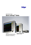
Infinity Vista XL Instructions for Use
WA R N I NG : F o r a f u l l u n d e r s ta n d i n g o f t h e p e r f o r m a n c e
characteristics of this device, the user should carefully
read this manual before use of the device.
Manufactured by:
Draeger Medical Systems, Inc.
3135 Quarry Road
Telford, PA 18969
Infinity Vista XL Instructions for Use
Software VF7
©Draeger Medical Systems, Inc. 2007.
All rights reserved.
Printed in the United States of America.
This device bears the H label in
accordance with the provisions of the
Directive 93/42/EEC of 14 June 1993
concerning medical devices (this label
is not applicable for US devices).
Distributed By:
Dräger Medical AG & Co. KG
Moislinger Allee 53-55
D-23558 Lübeck
Germany
Dräger reserves the right to modify the design and
specifications contained herein without prior notice.
Please contact your local Dräger Sales
Representative for the most current information.
Reproduction in any manner, in whole or in part, in
English or in any other languages, except for brief
excerpts in reviews and scientific papers, is prohibited
without prior written permission of Dräger Medical AG
& Co. KG.
All Dräger devices are intended for use by trained
medical personnel only.
CAUTION: In the United States, Federal
Law restricts these devices to sale by, or on
order of a physician.
Before using any Dräger devices, carefully read all
the manuals that are provided with your device.
Patient monitoring equipment, however sophisticated,
should never be used as a substitute for the human
care, attention, and critical judgment that only trained
health care professionals can provide.
ACE, MultiMed, Cardiology Review Station, Scio, and
OxiSure are registered trademarks of Dräger Medical
AG & Co. KG.
CAPNOSTAT is a registered trademark of Novametrix
Medical Systems, Inc.
Masimo, Masimo SET and Signal Extraction
Technology (SET) are registered trademarks of
Masimo Corporation.
SILICON SOFTWARE © 1989, 90, 91, 92, 93, 94
Microtec Research Inc.
All rights reserved
Some graphics courtesy of Novametrix Medical
Systems, Inc.
Unpublished rights reserved under the copyright laws
of the United States
RESTRICTED RIGHTS LEGEND Use duplication or
disclosure by the Government is subject to
restrictions as set forth in subparagraph (c)(1)(ii) of
the Rights in Technical Data & Computer Software
clause at DFARS 252 227:7013
MICROTEC RESEARCH INC. 2350 MISSION
COLLEGE BLVD.
SANTA CLARA CA 95054
Microstream is a registered trademark of Oridion
Medical 1987 Ltd.
All other brand or product names are trademarks or
registered trademarks of their respective companies.
This device is subject to EU Directive 2002/96/EC
(WEEE). It is not registered for use in private
households, and may not be disposed of at municipal
collection points for waste electrical and electronic
equipment. Dräger Medical has authorized a firm to
dispose of this device in the proper manner. For more
detailed information, please contact your local Dräger
Medical organization.
Overview
Overview........................................................................................................................... III
Intended Use ....................................................................................................................IV
Indications For Use ..........................................................................................................V
Documentation Features ................................................................................................VI
Notes, Cautions, Warnings
............................................................................VI
Cross-references.......................................................................................................VI
Quick Reference Tables ...........................................................................................VI
Footer .........................................................................................................................VI
Applicability...............................................................................................................VI
Safety Considerations....................................................................................................VII
Site of Operation ......................................................................................................VII
Inspection and Maintenance ...................................................................................VII
General Electrical Safety ..........................................................................................IX
Pacemakers ...............................................................................................................IX
Peripheral Devices ................................................................................................IX
Electrosurgery...........................................................................................................IX
Electromagnetic Compatibility.......................................................................................XI
Table of Contents ...........................................................................................................XII
INFINITY VISTA XL USER ’S GUIDE
Intended Use
The Infinity Vista XL monitors are intended for multi-parameter patient monitoring.
The devices will produce visual and audible alarms if any of the physiological
parameters monitored vary beyond preset limits, and timed or alarm recordings will be
produced. These devices will connect to R50 recorders either directly or via the
Infinity network.
IV
VISTA XL
VF7
INFINITY VISTA XL USER ’S GUIDE
Indications For Use
The Infinity Vista XL monitors are capable of monitoring:
z
Heart rate
z
Respiration rate
z
Invasive pressure
z
Noninvasive pressure
z
Arrhythmia
z
Temperature
z
Cardiac Output
z
Arterial oxygen saturation
z
Pulse rate
z
Apnea
z
ST Segment Analysis
z
12-Lead ST Segment Analysis
z
FiO2
The devices are intended for use in the environment where patient care is provided by
Healthcare Professionals, i.e. Physicians, Nurses, and Technicians who will determine
when use of the device is indicated, based upon their professional assessment of the
patient's medical condition. The devices are intended to be used on Adult, Pediatric
and Neonatal populations with the exception of the parameter cardiac output, STsegment analysis, and arrhythmia which are intended for use in the adult and pediatric
populations only.
The Infinity Modular Monitors are not compatible for use in a MRI magnetic field.
VF7
VISTA XL
V
INFINITY VISTA XL USER ’S GUIDE
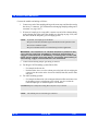
Documentation Features
Warnings, Cautions, Notes
WA R N I N G ! A w a r n i n g s ta t e m e n t p r o v i d e s i m p o r ta n t
i n f o r m a t i o n a b o u t a p o t e n t i a l l y h a z a r d o u s s i t u a t i o n w hi c h , i f
n o t a v o i d e d , c o u l d re s u l t in d e a t h o r s e ri o u s i n j u r y.
CAUTION! A caution statement provides important information about a potentially
hazardous situation which, if not avoided may result in minor or moderate injury to the
user or patient, or in damage to the equipment or other property.
NOTE: A note provides additional information intended to avoid inconvenience
during operation.
Cross-references
Cross-references specify chapter and page (e.g., page 16-3 refers to Chapter 16, page
3). Chapter number and title are given when text refers to an entire chapter (e.g.,
Chapter 1, Introduction).
Quick Reference Tables
Wherever possible, a quick reference table is provided for easy access to information
about monitor functions.
Footer
The current software version appears at the bottom of each page, together with the
chapter and page number and the device name.
Applicability
All references to “the monitor” in this manual refer to the Vista XL patient monitor.
VI
VISTA XL
VF7
INFINITY VISTA XL USER ’S GUIDE
Safety Considerations
This Instructions for Use assumes a working knowledge of patient monitors. To
support proper, safe and accurate operation of equipment, read all operating
instructions carefully before you use the monitor. The monitor complies with IEC
60601-1 and applicable collateral and particular standards.
Site of Operation
WA R N I N G :
z
C o n n e c t t h e A C A d a pt e r t o h os pi ta l g r a d e e l e c t r i c a l
o u t l e ts w i t h m e d i c a l p ow e r c o r d s .
z
M o n i t o r o p e r a t i o n i s n o t c u r r e n t l y s u p p o rt e d i n t h e
f o l l o w i n g e nv i r on me nts : m a g ne t i c r e s o n a n c e i m a g i n g
( M R I ) e n v i r o n m e n ts , a i r c r a ft , a m b u l a n c e , h o m e o r
h y p e r b a r i c c h a mb e r e n v i r o n m e n ts .
z
D o n o t o p e r a t e t h e m o n i t o r o r i ts r e m o t e d i s p l a y s i n t h e
p re s e n c e o f f l a m m a b l e g a s e s .
z
D o n o t u s e t h e m o n i t o r n e a r d e v i c e s w i t h m i c ro w a v e o r
o t h e r h i g h- f r e q ue nc y e m i s s i o ns . T he s e e m i s s i o n s m a y
i n t e r f e r e w i t h t h e m o n i t o r ’s o p e r a t i o n .
z
P os iti on the m on ito r a nd ac ce ss ori es w ith at le as t 2 i n.
( 5 c m. ) o f s pac e a ro und a ll si des to p rev en t o ve rhe at ing .
z
D o n o t a l l o w f l u i d s t o c om e i n c o n ta c t w i t h m o n i t o r o r
p e r i p h e r a l s . I f f l u i d s a r e a c c i d e n ta l l y s p i l l e d o n
equipment, remove affected unit from service as soon
a s p o s s i b l e . C o n ta c t y o u r b i o m e d t o e n s u r e t h a t t h e r e
i s n o c o m p r o m i s e i n e l e c t r i c a l s a f e t y.
CAUTION:
z
The site of operation must meet the environmental requirements outlined in
Appendix B, Technical Data.
z
To avoid patient injury, ensure patient is disconnected from all sensors, etc.
before moving patient.
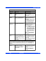
Inspection and Maintenance
Regular equipment inspection and maintenance is required. The user should verify
that the monitor operates as described in this manual and that all safety labels are
legible and should also maintain a record of these and other inspections. Safety
checks, verification, calibration and maintenance should be performed at least every
two years by trained personnel, as described in the Service Manual (see individual
VF7
VISTA XL
VII
INFINITY VISTA XL USER ’S GUIDE
parameter chapters for information about calibration and verification of parameterspecific functions and devices). All cables, alarm functions, accessories, and
associated devices should be checked for damage, ground resistance, chassis and
patient leakage currents on a yearly basis, or more frequently, based on usage.
WA R N I N G :
z
Disposable accessories (such as disposable
e l e c t r o d e s , t r a n s du c e r s , e t c . ) a r e f o r s i n g l e u s e o nl y.
Do not reuse disposable accessories.
z
D o n o t u s e c a b l e s t h a t a p p e a r c ra c k e d , w o r n , o r
d a m a g e d i n a n y w a y. S u c h u s e m a y c o n t r i b u t e t o p o o r
m o n i t o r i n g p e rf o rm a n c e o r t h e d i s p l a y o f e r ro n e o u s
values.
z
M o i s t u r e u n d e r t h e f r o nt pa n e l c a n d a m a g e t he e l e c t r i c
c i r c u i ts a n d c o m p r o m i s e k e y f u n c t i o n . R e a d c a r e f u l l y
c l e a n i n g i n s t r u c t i o n s o n pa g e 2 1 - 2 .
z
Because of the danger of electric shock, never remove
the cover of any device while it is in operation or
connected to a power outlet.
NOTE:
z
The monitor’s Service Manual is available from your local Dräger Medical
service representative.
z
Dispose of all equipment in accordance with local regulations.
Dräger Medical recommends:
VIII
z
Maintenance, modifications, and repairs are carried out by trained personnel.
z
Components are replaced with Dräger Medical provided spare parts,
otherwise the correct functioning of the device may be compromised.
z
Devices are used in accordance with Dräger Medical operating instructions,
as described in this Instructions for Use.
VISTA XL
VF7
INFINITY VISTA XL USER ’S GUIDE
General Electrical Safety
CAUTION:
z
Ensure electrical shock classifications for all equipment connected to the
patient are suitable for the intended application. Leakage current will increase
when connecting multiple medical devices to a patient.
z
It is the user’s responsibility to verify that the overall system is connected in
accordance with local regulations and your hospital’s policies, and that it
complies with EN 60601-1-1, “Collateral Standard: Safety Requirements for
Medical Electrical Systems.”
Pacemakers
NOTE: See “Pacemakers” on page 8-3 for safety precautions when monitoring paced
patients.
Peripheral Devices
CAUTION: In the interest of patient safety and equipment performance, the connection
of other manufacturers’ equipment to the monitor is not authorized, unless the
connection is explicitly approved by Dräger Medical. It is the user’s responsibility to
contact Dräger Medical to determine the compatibility and warranty status of any
connection made to another manufacturer’s equipment.
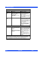
Electrosurgery
WA R N I N G :
z
K e e p E C G, t e m p e ra t u r e , p r e s s u r e , SpO2 tr a n s d u c e r s ,
and intermediate cables off earth ground and away from
ESU knife and return wires.
VF7
z
Use only Dräger blue ECG lead wires or the ESU block
w i t h c o n v e n t i o n a l l e a d s ( s e e pa g e 8 - 7 ) . T h e y a r e
d e s i g n e d t o p r o v i d e r e s i s ta n c e t o i n t e r f e re n c e f r o m t he
E S U a n d t o p ro t e c t t h e pa t i e n t f ro m b u r n s c a u s e d b y
E S U - i n d u c e d c ur r e n t f l o w i n g t hr o u g h t h e l e a ds .
z
I m p e d a n c e r e s p i r a t i o n m o n i t o r i n g a n d pa c e m a k e r s p i k e
d e t e c t i o n a re i n o p e r a t i v e w h e n y o u a re u s i n g t h e E SU
Block.
VISTA XL
IX
INFINITY VISTA XL USER ’S GUIDE
NOTE:
X
z
Use SpO2 or ART instead of the ECG parameter to determine heart rate.
z
Use rectal temperature probe sheaths to cover internally placed temperature
sensors.
z
Always use accessories designed for ESU environments.
VISTA XL
VF7
INFINITY VISTA XL USER ’S GUIDE
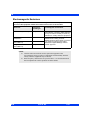
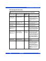
Electromagnetic Compatibility
The monitor has been designed and tested for compliance with current regulatory
standards (EN55011 Class B and EN60601-1-2) regarding its capacity to reduce
electromagnetic emissions (EMI) and to block EMI from external sources.
Dräger Medical recommends these procedures to reduce electromagnetic interference:
VF7
z
Use only Dräger Medical provided accessories, otherwise the correct
functioning of the device may be compromised (see Appendix C, Approved
Options and Accessories for more information).
z
Ensure that other products in patient-monitoring and/or life-support areas
comply to accepted emissions standards (EN55011, Class B).
z
Maximize distance between electromedical devices. High-power devices
relating to electrocautery, electrosurgery, and radiation (X-ray), as well as
electrical stimulators and evoked potential devices, may produce interference
on the monitor.
z
Strictly limit access to portable radio-frequency sources (e.g., cellular phones
and radio transmitters). Portable phones may periodically transmit even when
in standby mode.
z
Maintain good cable management. Avoid routing cables over electrical
equipment. Do not intertwine cables.
z
Ensure electrical maintenance is done by qualified personnel.
z
NBP circuits use motors that emit very low-level electromagnetic fields that
may interfere with other sensitive medical devices.
z
For more information on Electromagnetic Compatibility, see B-2
VISTA XL
XI
INFINITY VISTA XL USER ’S GUIDE
Table of Contents
CHAPTER 1: Introduction
Overview.........................................................................................................................1-2
System Components.....................................................................................................1-3
Base Unit .................................................................................................................1-3
Device Markings......................................................................................................1-6
Modules ...................................................................................................................1-8
Other Features and Components ..........................................................................1-8
Power Sources...............................................................................................................1-9
Battery Power ..........................................................................................................1-9
Getting Started.............................................................................................................1-12
Turning the Monitor On and Off...........................................................................1-12
Accessing the Main Screen .................................................................................1-12
Using the Rotary Knob .........................................................................................1-13
Remote Keypad .....................................................................................................1-14
Menu Access................................................................................................................1-15
Fast Access Menu.................................................................................................1-15
Main Menu .............................................................................................................1-15
Fixed Keys .............................................................................................................1-16
Control Buttons.....................................................................................................1-16
Data Archive Applications ..........................................................................................1-16
Storing Events.......................................................................................................1-17
Event Recall...........................................................................................................1-18
Navigating the Event Recall Screen ....................................................................1-20
Help Functions.............................................................................................................1-21
CHAPTER 2: Monitor Setup
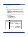
Overview.........................................................................................................................2-2
Configuring the Monitor................................................................................................2-2
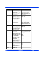
Main Menu Setup ....................................................................................................2-2
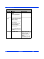
Quick Reference -- Main Menu Setup....................................................................2-3
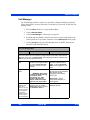
Setups Management....................................................................................................2-10
Specialty Menus ..........................................................................................................2-11
OR Mode ................................................................................................................2-11
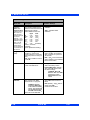
Unit Manager .........................................................................................................2-13
Biomed ...................................................................................................................2-17
Parameter Colors ..................................................................................................2-19
CHAPTER 3: Network Applications
Overview.........................................................................................................................3-2
XII
VISTA XL
VF7
INFINITY VISTA XL USER ’S GUIDE
Connecting to the Network...........................................................................................3-3
Connecting the Vista XL to the Network...............................................................3-3
Network Message....................................................................................................3-3
Disconnecting the Vista XL from the Network .....................................................3-3
Wireless Network...........................................................................................................3-4
Wireless Network Safety Considerations .............................................................3-4
Wireless Network Setup .........................................................................................3-5
Wireless Mode ........................................................................................................3-6
Wireless Messages .................................................................................................3-7
Network Transfer ...........................................................................................................3-9
Patient Data .............................................................................................................3-9
Software Licenses...................................................................................................3-9
Remote View ................................................................................................................3-10
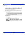
Privacy..........................................................................................................................3-13
CHAPTER 4: Admission, Transfer, and Discharge
Overview.........................................................................................................................4-2
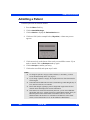
Admitting a Patient........................................................................................................4-3
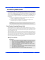
Transferring Patient Data.............................................................................................4-4
Data Transfer Using the Memory Card..................................................................4-4
Network Data Transfer............................................................................................4-6
Discharging a Patient....................................................................................................4-7
CHAPTER 5: Alarms
Overview.........................................................................................................................5-2
Alarm Grades .................................................................................................................5-2
Alarm Management .......................................................................................................5-4
Suspending Alarms ................................................................................................5-4
Alarm Control ..........................................................................................................5-4
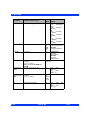
Alarm Setup (Alarm Limits Table)................................................................................5-5
Upper and Lower Alarm Limits ..............................................................................5-7
Modifying Alarm Functions..................................................................................5-13
Quick Reference -- Alarm Limits Table Setup ....................................................5-14
Alarm Limits Shortcut...........................................................................................5-15
ST and Arrhythmia Alarms...................................................................................5-15
Alarm History Table.....................................................................................................5-15
Anesthesia Alarms ......................................................................................................5-16
CHAPTER 6: Trends
Overview.........................................................................................................................6-2
Trend Setup....................................................................................................................6-2
Trend Graphs .................................................................................................................6-4
VF7
VISTA XL
XIII
INFINITY VISTA XL USER ’S GUIDE
Trend Table ....................................................................................................................6-7
Mini-Trends ....................................................................................................................6-8
CHAPTER 7: Recordings
Overview.........................................................................................................................7-2
Recordings.....................................................................................................................7-2
Layout ......................................................................................................................7-2
Timed .......................................................................................................................7-6
Continuous ..............................................................................................................7-6
Events and Trends ..................................................................................................7-7
Pending Recordings ...............................................................................................7-7
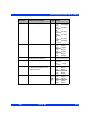
Recorder Setup..............................................................................................................7-7
Quick Reference: R50 Series Setup Menu............................................................7-8
Primary and Secondary Recorders .......................................................................7-9
Replacing Recorder Paper ...................................................................................7-10
Reports .........................................................................................................................7-11
Quick Reference: Reports Setup .........................................................................7-12
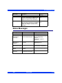
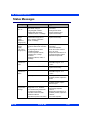
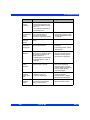
Status Messages .........................................................................................................7-13
CHAPTER 8: ECG and Heart Rate
Overview.........................................................................................................................8-2
ECG Precautions ...........................................................................................................8-3
Pacemakers .............................................................................................................8-3
Electrosurgery.........................................................................................................8-6
Infusion or Roller Bypass Pumps .........................................................................8-7
Line Isolation Devices ............................................................................................8-8
Transcutaneous Electrical Nerve Stimulators......................................................8-8
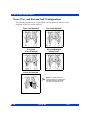
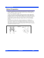
Patient Preparation........................................................................................................8-9
Three-, Five-, and Six-Lead TruST Configurations ............................................8-10
Derived Twelve-Lead Configuration (TruST) ......................................................8-11
ECG Signal Processing and Display .........................................................................8-12
TruST 12-Lead .....................................................................................................8-13
Alarms and Alarm Conditions ....................................................................................8-14
ECG Setup Menu .........................................................................................................8-15
Quick Reference Table -- ECG Setup ..................................................................8-15
Status Messages .........................................................................................................8-21
CHAPTER 9: Arrhythmia Monitoring
Overview.........................................................................................................................9-2
About the Arrhythmia Template...................................................................................9-2
Beat and Rhythm Classification ............................................................................9-3
Automatic Learning and Relearning .....................................................................9-4
XIV
VISTA XL
VF7
INFINITY VISTA XL USER ’S GUIDE
Arrhythmia Setup ..........................................................................................................9-4
Modes (Full, Basic, OFF) ........................................................................................9-4
Channel - Lead Selection .......................................................................................9-5
Arrhythmia Setup Table..........................................................................................9-6
Status Messages ...........................................................................................................9-9
CHAPTER 10: ST Monitoring
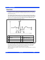
Overview.......................................................................................................................10-2
MultiMed Pods for ST Analysis ..................................................................................10-3
ST Display ....................................................................................................................10-3
ST Analysis Setup .......................................................................................................10-3
Quick Reference: ST Analysis Menu...................................................................10-4
Measuring Points ..................................................................................................10-5
ST Alarms Table ..........................................................................................................10-7
Status Messages .........................................................................................................10-8
CHAPTER 11: Respiration
Overview.......................................................................................................................11-2
RESP Precautions .......................................................................................................11-3
Patient Preparation......................................................................................................11-4
Display Features..........................................................................................................11-5
RESP Setup Menu .......................................................................................................11-6
Quick Reference Table -- Respiration Setup ......................................................11-7
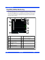
OxyCRG (OCRG) Monitoring ....................................................................................11-10
Scale.....................................................................................................................11-11
Cursor ..................................................................................................................11-11
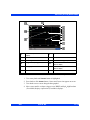
Review Summary Screen Overview ..................................................................11-11
Accessing Review Summary Screen ................................................................11-13
Quick Reference Table -- OCRG Review Summary .........................................11-17
OCRG Setup Menu ..............................................................................................11-17
Quick Reference Table -- OCRG Setup .............................................................11-18
Second and Third Channel Label ......................................................................11-18
Time Base ............................................................................................................11-18
Recordings ..........................................................................................................11-19
Status Messages .......................................................................................................11-20
CHAPTER 12: Non-Invasive Blood Pressure
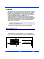
Overview.......................................................................................................................12-2
Display Features..........................................................................................................12-2
NBP Setup ....................................................................................................................12-3
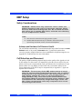
Safety Considerations
.....................................................................................12-3
Cuff Selection and Placement..............................................................................12-3
VF7
VISTA XL
XV
INFINITY VISTA XL USER ’S GUIDE
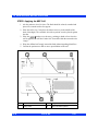
Setup Menu and Quick Reference Table.............................................................12-7
Taking NBP Measurements..................................................................................12-8
Venous Stasis .....................................................................................................12-10
Status Messages .......................................................................................................12-11
CHAPTER 13: Invasive Blood Pressure
Overview.......................................................................................................................13-2
Precautions ..................................................................................................................13-3
Hardware Setup ...........................................................................................................13-4
Tubing ....................................................................................................................13-4
Transducers ..........................................................................................................13-4
Hemomed...............................................................................................................13-7
IBP Y-Cables..........................................................................................................13-7
Display Features..........................................................................................................13-8
IBP Setup....................................................................................................................13-10
Quick Reference -- IBP Setup ............................................................................13-11
Labeling Pressure Channels..............................................................................13-12
Pressure Label Conflicts ....................................................................................13-13
Pulmonary Wedge Pressure Display .......................................................................13-13
Status Messages .......................................................................................................13-15
CHAPTER 14: Calculations
Overview.......................................................................................................................14-2
Physiological Calculations .........................................................................................14-3
HemoMed Parameters ..........................................................................................14-5
Oxygenation and Ventilation Parameters ...........................................................14-7
Drug Calculations........................................................................................................14-7
Titration Tables .....................................................................................................14-8
Drug Calculator Setup ..........................................................................................14-9
Default Drug Setup (Unit Manager) ...................................................................14-11
CHAPTER 15: Pulse Oximetry (SpO2)
Intended Use ................................................................................................................15-2
Overview.......................................................................................................................15-3
Precautions ..................................................................................................................15-3
Patient Preparation......................................................................................................15-5
Display Features..........................................................................................................15-7
SpO2 Setup ..................................................................................................................15-8
Quick Reference Table -- SpO2 Setup ................................................................15-8
Status Messages .......................................................................................................15-9
SpO2 MicrO2+® .........................................................................................................15-12
Overview ..............................................................................................................15-12
XVI
VISTA XL
VF7
INFINITY VISTA XL USER ’S GUIDE
Parameters...........................................................................................................15-12
SpO2 MicrO2+ Setup ..........................................................................................15-12
SpO2 MicrO2+ Trends ........................................................................................15-13
Status Messages .................................................................................................15-14
..............................................................................................................................15-15
CHAPTER 16: etCO2 (End-Tidal CO2) Monitoring
Overview.......................................................................................................................16-2
Sampling Methods.......................................................................................................16-3
Mainstream ............................................................................................................16-3
Sidestream (Adult and Pediatric Patients Only).................................................16-3
Display Features..........................................................................................................16-5
Parameters.............................................................................................................16-6
Capnograms ..........................................................................................................16-7
etCO2 Setup .................................................................................................................16-8
Quick Reference Table--etCO2 Setup .................................................................16-9
Cleaning, Calibration and Verification.....................................................................16-12
Cleaning ...............................................................................................................16-12
Adapter Calibration.............................................................................................16-12
Sensor Calibration and Verification ..................................................................16-12
Status Messages .......................................................................................................16-14
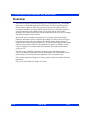
CHAPTER 17: FiO2 (Fractional Inspired O2) Monitoring
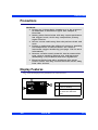
Overview.......................................................................................................................17-2
Precautions ..................................................................................................................17-3
Display Features..........................................................................................................17-3
FiO2 Setup....................................................................................................................17-4
Menu Access .........................................................................................................17-4
Calibration .............................................................................................................17-4
Status Messages .........................................................................................................17-6
CHAPTER 18: Scio® Four Modules
Intended Use ................................................................................................................18-2
Overview ......................................................................................................................18-3
Scio Four Oxi plus ................................................................................................18-3
Scio Four Oxi.........................................................................................................18-4
Scio Four plus .......................................................................................................18-4
Scio Four................................................................................................................18-5
Hardware Setup ...........................................................................................................18-8
Site of Operation ...................................................................................................18-9
Installing the Water Trap ....................................................................................18-10
Cable Connections..............................................................................................18-11
VF7
VISTA XL
XVII
INFINITY VISTA XL USER ’S GUIDE
Tubing Connections ........................................................................................18-11
Warm-Up ..............................................................................................................18-14
Calibration ...........................................................................................................18-14
Scio Setup ..................................................................................................................18-14
etCO2* Monitoring ..............................................................................................18-14
O2/N2O Monitoring (Scio Four Oxi plus and Scio Four Oxi only) .................18-16
Agent Monitoring ................................................................................................18-18
MAC Values .........................................................................................................18-20
Combined Display (O2/Agent/N2O) (Scio Four Oxi plus only) .......................18-24
Dual Agent Display (Scio Four Oxi plus & Scio Four plus only) ....................18-26
Maintenance and Repair ...........................................................................................18-26
Status Messages .......................................................................................................18-29
CHAPTER 19: Body Temperature
Overview.......................................................................................................................19-2
Temperature Display ...................................................................................................19-3
Temperature Setup......................................................................................................19-4
ESU and Defibrillator Precautions .............................................................................19-4
Status Messages .........................................................................................................19-5
CHAPTER 20: Cardiac Output
Overview.......................................................................................................................20-2
Accuracy ......................................................................................................................20-3
Main Screen Display....................................................................................................20-4
C.O. Setup ....................................................................................................................20-5
Hardware................................................................................................................20-5
C.O. Setup Menu ...................................................................................................20-5
Quick Reference -- C.O. Setup .............................................................................20-5
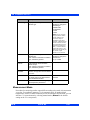
Measurement Mode ..............................................................................................20-6
Catheters (Comp. Constant) ................................................................................20-7
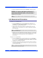
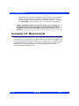
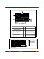
C.O. Measurement Procedures ..................................................................................20-9
Averaging C.O. Measurements ................................................................................20-10
HemoMed Calculations (MiniCalcs).........................................................................20-12
Status Messages .......................................................................................................20-14
CHAPTER 21: Cleaning and Disinfecting
Overview.......................................................................................................................21-2
Monitor and Peripheral Devices ..........................................................................21-2
Patient Cables .......................................................................................................21-2
ECG...............................................................................................................................21-3
Reusable ECG Electrodes ....................................................................................21-3
ESU Block ..............................................................................................................21-3
XVIII
VISTA XL
VF7
INFINITY VISTA XL USER ’S GUIDE
NBP ...............................................................................................................................21-3
IBP.................................................................................................................................21-4
Transducers...........................................................................................................21-4
HemoMed Transducer Plate.................................................................................21-4
SpO2 ............................................................................................................................21-4
SET Pod .................................................................................................................21-4
etCO2 ............................................................................................................................21-5
Capnostat Sensor .................................................................................................21-5
Airway Adapter......................................................................................................21-5
Sidestream Sampling Pump (etCO2 only) ..........................................................21-5
FiO2...............................................................................................................................21-7
Temperature.................................................................................................................21-7
APPENDIX A: Glossary
APPENDIX B: Technical Data
Overview........................................................................................................................ B-2
Overall Regulatory Standard Compliance.................................................................. B-2
Electromagnetic Compatibility.................................................................................... B-2
Electromagnetic Emissions ................................................................................. B-4
Electromagnetic Immunity ................................................................................... B-5
Recommended separation distances .................................................................. B-6
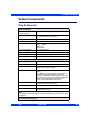
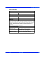
System Components.................................................................................................... B-7
Vista XL Base Unit ................................................................................................. B-7
External Battery...................................................................................................... B-9
Battery Charger .................................................................................................... B-10
R50 N Infinity Recorder ....................................................................................... B-10
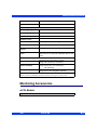
Monitoring Accessories............................................................................................. B-11
etCO2 Module ....................................................................................................... B-11
HemoMed .............................................................................................................. B-13
Scio Four/Scio Four Oxi/Scio Four plus/Scio Four Oxi plus Module............. B-13
FiO2 Sensors ........................................................................................................ B-15
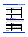
Monitoring Specifications.......................................................................................... B-15
ECG ....................................................................................................................... B-15
ST-Segment Analysis .......................................................................................... B-16
Respiration ........................................................................................................... B-17
Non-Invasive Blood Pressure (NBP) .................................................................. B-17
Invasive Blood Pressure (IBP) ............................................................................ B-19
Cardiac Output ..................................................................................................... B-19
Pulse Oximetry (SpO2) ........................................................................................ B-19
Pulse Oximetry (SpO2) Via Masimo SET SmartPod ...................................... B-22
End-Tidal CO2 (etCO2) via etCO2 module ........................................................ B-23
FiO2 ....................................................................................................................... B-24
VF7
VISTA XL
XIX
INFINITY VISTA XL USER ’S GUIDE
Temperature ......................................................................................................... B-24
APPENDIX C: Approved Options and Accessories
Power Supply................................................................................................................ C-3
Power Cords ........................................................................................................... C-3
Power Adapters...................................................................................................... C-3
Grounding Cable .................................................................................................... C-3
External Battery ..................................................................................................... C-3
Connections.................................................................................................................. C-3
Monitor Connecting Cables .................................................................................. C-3
R50 Recorder Cables ............................................................................................. C-4
Recorders...................................................................................................................... C-4
Vista XL Monitor Options............................................................................................. C-4
ECG................................................................................................................................ C-6
MultiMed and NeoMed Pods ................................................................................. C-6
Leads....................................................................................................................... C-6
Miscellaneous ECG................................................................................................ C-8
Pulse Oximetry (SpO2) ................................................................................................ C-9
Dräger Sensors ..................................................................................................... C-9
Masimo Sensors ................................................................................................... C-9
Nellcor Sensors ................................................................................................... C-10
Pods ...................................................................................................................... C-10
Cables ................................................................................................................... C-10
Temperature................................................................................................................ C-11
Core Probes.......................................................................................................... C-11
Skin Probes ......................................................................................................... C-11
Non-Invasive Blood Pressure (NBP)......................................................................... C-12
NBP Cuffs ............................................................................................................. C-12
NBP Connecting Hoses ....................................................................................... C-12
Invasive Blood Pressure (IBP) .................................................................................. C-12
Vista XL IBP Options .......................................................................................... C-12
HemoMed Pod ...................................................................................................... C-12
Connecting Cables .............................................................................................. C-12
IBP Accessories — Ohmeda ............................................................................... C-14
IBP Accessories — Abbott/Medex ..................................................................... C-14
IBP Accessories — Edwards/Baxter .................................................................. C-14
IBP Accessories —SensoNor ............................................................................. C-14
End-Tidal CO2 (etCO2)............................................................................................... C-14
etCO2 Module ...................................................................................................... C-14
Sensors ................................................................................................................. C-15
Main-Stream Accessories ................................................................................... C-15
Side-Stream Accessories .................................................................................... C-15
FiO2.............................................................................................................................. C-15
MultiGas Monitoring................................................................................................... C-16
XX
VISTA XL
VF7
INFINITY VISTA XL USER ’S GUIDE
Scio Connecting Cables ...................................................................................... C-16
Scio Module .......................................................................................................... C-16
Accessories ......................................................................................................... C-16
VF7
VISTA XL
XXI
INFINITY VISTA XL USER ’S GUIDE
- This page intentionally left blank -
XXII
VISTA XL
VF7
Chapter 1 Introduction
Overview............................................................................................................................2
System Components ........................................................................................................3
Base Unit.....................................................................................................................3
Device Markings .........................................................................................................6
Modules.......................................................................................................................8
Auxiliary Display Components .................................................................................8
Other Features and Components .............................................................................9
Power Sources................................................................................................................10
Battery Power ...........................................................................................................10
Getting Started................................................................................................................13
Turning the Monitor On and Off..............................................................................13
Accessing the Main Screen.....................................................................................13
Using the Rotary Knob ............................................................................................14
Remote Keypad ........................................................................................................15
Menu Access...................................................................................................................16
Fast Access Menu ....................................................................................................16
Main Menu.................................................................................................................16
Fixed Keys ................................................................................................................17
Control Buttons ........................................................................................................17
Data Archive Applications .............................................................................................17
Storing Events ..........................................................................................................18
Event Recall ..............................................................................................................19
Navigating the Event Recall Screen .......................................................................21
Help Functions................................................................................................................22
1 INTRODUCTION
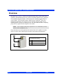
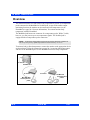
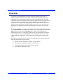
Overview
The patient monitor is intended for adult, pediatric, and neonatal monitoring. It can be
used as a standalone device or can be connected to the Infinity network. Monitor use is
restricted to one patient at a time.
The following optional software features are available:
1-2
z
ACE full arrhythmia (Arrhythmia II)
z
HemoMed & oxygenation/ventilation calculations (physiological
calculations)
z
3-lead ST segment analysis
z
Waveform channel upgrades
z
Aries (Advanced Review of Ischemia Event System)
z
Wireless Networking
z
OR mode
VISTA XL
VF7
SYSTEM COMPONENTS
System Components
NOTE:
Monitor configuration may vary. See your Biomed for more information.
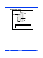
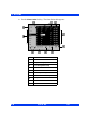
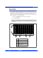
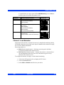
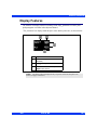
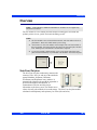
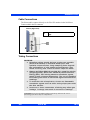
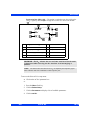
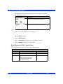
Base Unit
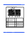
Monitor Front View--Vista XL
VF7
1
Fixed keys
2
Main Menu fixed key
3
Main Screen fixed key
4
Battery Charge indicator
5
Power switch
VISTA XL
1-3
1 INTRODUCTION
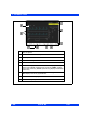
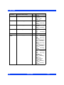
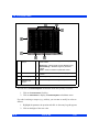
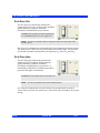
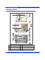
Monitor Rear View--Vista XL
1-4
1
External (lead-acid) battery
compartment
2
Remote Display (x5), R50 (x7)
3
Connector for AC adaptor
4
Slot for etCO2 module
VISTA XL
VF7
SYSTEM COMPONENTS
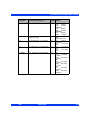
Monitor Left Side--Vista XL
VF7
1
HemoMed connector
2
MultiMed connector
3
NBP connector
VISTA XL
1-5
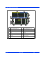
1 INTRODUCTION
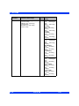
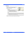
Monitor Right Side--Vista XL
1
PCMCIA slot
2
Network connector
3
QRS Sync connector
4
RS 232 connector (X8)
5
Analog connector (X10)
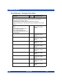
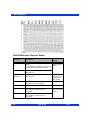
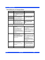
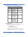
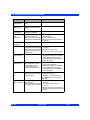
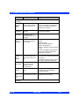
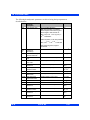
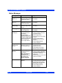
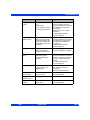
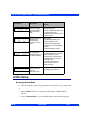
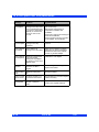
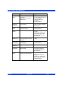
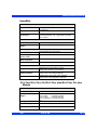
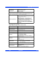
Device Markings
The following table describes the symbols on the monitor and its accessories:
1-6
&
Monitor on/off
Remote keypad in
@
Battery-operated
equipment
RS 232
Attention! Consult the
accompanying document
Analog out
Defibrillator-proof equipment,
Type CF
Analog out
VISTA XL
VF7
SYSTEM COMPONENTS
Direct current
Analog out
Danger: Risk of explosion if
used in presence of flammable
anesthetics
Push battery all the way into
compartment.
A
Isolated patient connection,
Type CF
Close battery compartment
door.
H0123
Complies with the European
Medical Device Directive 93/
42/EEC
.
This end up
Type BF, defibrillator
protected
Artery symbol and arrow
should be placed over
brachial or femoral artery.
:
Gas in
Contains no latex material
;
Gas out
Manufacturer’s lot number
E
Dispose of properly
Certain cuff codes are
ethylene oxide sterile.
Manufacturing date
REF
Manufacturer’s reorder code
Alarm out
Does not provide isolation
between connected devices
∼
Monitor is receiving AC power
Potential equalization
terminal
F
Observe WEEE (Waste
Electrical and Electronic
Equipment) disposal
requirements
VF7
VISTA XL
1-7
1 INTRODUCTION
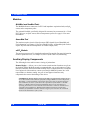
Modules
MultiMed and NeoMed Pods
The MultiMed houses connectors for ECG and impedance respiration leads, an SpO2
sensor, and a temperature probe.
The optional NeoMed, specifically designed for neonates, has connectors for a 3-lead
ECG cable set, an SpO2 sensor, and two temperature probes. See page 8-2 for more
information.
HemoMed Pod
The monitor acquires invasive blood pressure (IBP) signals from a HemoMed pod.
For information, see Chapter 13, Invasive Blood Pressure. A HemoMed pod can also
acquire injectate and blood temperature for cardiac output (20-4).
etCO2 Module
The monitor processes etCO2 signals through an etCO2 module. For more information
on these optional devices, see Chapter 16, etCO2 (End-Tidal CO2) Monitoring.
Auxiliary Display Components
The following devices enable remote viewing of patient data.
Remote Display -- Allows you to view but not control monitor functions away from
the bedside. Dräger Medical strongly recommends that you use only approved video
monitors, otherwise the function of the monitor may be compromised. For a complete
list of approved video monitors, contact your Draeger Medical Systems, Inc. local
representative to obtain a catalog. Any use of non-approved monitors may
compromise the correct functioning of the device.
CAUTION: The Remote Display output on the IDS is not galvanically isolated. If you
use a video monitor other than one specified by Dräger Medical, it must comply with
IEC 60601-1. Upon installation, the installer must ensure that, in normal and single
fault conditions, the entire system meets the requirements of IEC 60601-1 and IEC
60601-1-1 (Medical Electrical Systems Standards). Refer to the video monitor’s
operating instructions to ensure that the interconnection is within its intended use as
specified by the manufacturer. Radiated and conducted emissions classification,
suitability for flammable locations and water ingress protection must be considered
based on the intended use of the system.
1-8
VISTA XL
VF7
SYSTEM COMPONENTS
Other Features and Components
VF7
z
Remote Keypad--The optional Remote Keypad allows you to operate the
monitor from a distance. A rotary knob and fixed keys duplicate those of the
monitor, while a numeric keypad allows you to enter data. See page 1-15 for
more information.
z
Export Protocol--Allows you to share data with other Dräger Medical and
third-party devices (e.g., Clinical Information and Anesthesia Record Systems
and Data Loggers; see Dräger Medical publication Infinity RS-232 Export
Protocol Reference Booklet).
z
Arrhythmia Classification Expert (ACE)--Detects cardiac events, reduces
false alarms, and filters out misleading or erroneous arrhythmia data.
z
R50 Series Recorders--Produce alarm, timed, continuous, and trend
recordings. See Chapter 7, Recordings, for more information about R50 and
R50-N recorders.
z
PCMCIA Card--Allows you to transfer data, upgrade software, store setups,
download setups, and store diagnostic logs.
z
QRS Sync. Output--Allows you to synchronize defibrillators to the patient’s
heart beat during cardioversion.
z
Balloon Pump Interface--Permits interaction with a balloon pump by
providing two analog output signals (ECG and ART).
VISTA XL
1-9
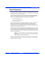
1 INTRODUCTION
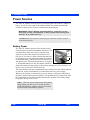
Power Sources
The Vista XL monitor can be powered by a hospital grade outlet with AC adapter, or
battery. In case of a line outage or disconnected cable, the monitor automatically
switches to battery power to ensure continued patient monitoring.
WA R N I N G : R e a d “ S a f e t y C o n s i d e r a t i o n s ” ( pa g e V I I, i n t h e
Overview of this Instructions fo Use) before connecting the
m o n i t o r t o a p o w e r s o u rc e .
CAUTION: Make sure all power cords are properly connected, or batteries may be
drained unintentionally.
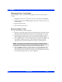
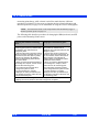
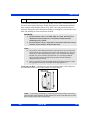
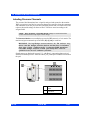
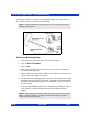
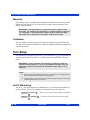
Battery Power
The Vista XL monitor operates on an external, sealed
Insert
battery
lead-acid battery and an internal lithium-ion battery. The
here
external battery, which can easily be replaced when
depleted, can power the monitor for 50 minutes. If it
runs low or you remove it from a monitor that has been
Battery
using battery power, the monitor automatically switches
to an internal battery, which can power the monitor for
180 minutes (See “Electrical Specifications” on page B7). When both batteries run low, the monitor sounds an
alarm, and a status message appears in the network message area. If both batteries are
depleted, the monitor turns off automatically.
The external battery fits into a compartment on the monitor’s left side. When depleted
or removed, replace it immediately or connect the monitor to a power supply.
Whenever the monitor is connected to power, the battery is charged (as indicated by
the battery charger LED on the front panel). The internal battery is charged first, then
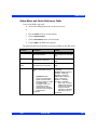
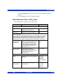
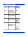
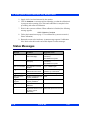
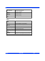
the external battery.The following table illustrates the function of the battery charge
bar graph at the top of the screen:
When AC power is disconnected, the battery
charge display can take up to 15 seconds to reflect
actual internal battery capacity and up to 60 seconds
to reflect actual external battery capacity
NOTE:
1-10
VISTA XL
VF7
POWER SOURCES
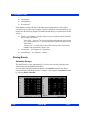
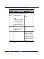
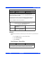
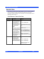
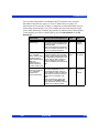
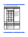
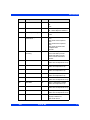
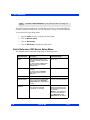
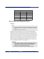
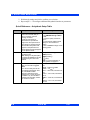
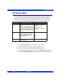
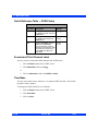
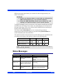
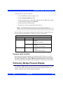
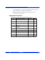
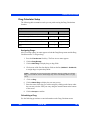
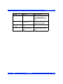
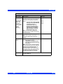
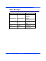
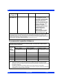
Battery Charge Display
Display
Charge Left
Action
Battery in use is fully charged.
N/A
Battery in use is half full.
Connect AC adapter.
External battery is very low (<
25%).
Replace with fully charged
external battery.
External battery is depleted.1
Replace with fully charged
external battery.
Internal battery is very low
(<25%).
Immediately connect monitor to
AC adapter. Replace external
battery.
Internal battery is depleted; <5
minutes of power remaining.2
1
Monitor sounds single attention tone. 2Monitor sounds attention tone every 5
seconds.
WA R N I N G : A c t u a l t i m e a v a i l a b l e o n t h e i n t e r n a l b a t t e r y c a n
b e s i g n i f i c a n t l y r e d u c e d w it h w o r n o u t o r d e f e c t i v e b a t t e r i e s .
T h e ‘ I n t e r n a l B a t t e r y P e r c e n ta g e ’ v a l u e o n t h e B a t t e r y Sta t u s
s c r e e n i s a c c u r a t e o n l y i f t h e b a t t e r i e s a re i n n o r m a l w o r k i n g
condition.
CAUTION:
VF7
z
DO NOT use the monitor for transport if the internal battery charge is at 25%
or less, unless you are using a fully charged external battery.
z
High temperatures may adversely affect batteries. For optimal performance,
charge and use the external batteries at temperatures below 35°C (95°F).
z
Follow local regulations for safe disposal of batteries. To prevent fire or
explosion, never dispose of batteries in fire.
z
Use only batteries that are provided by Dräger Medical. The use of nonapproved batteries may damage the device.
VISTA XL
1-11
1 INTRODUCTION
NOTE:
z
To retain charge during transport, leave the monitor connected until you are
ready to move the patient. Reconnect the monitor immediately after transport.
Dräger Medical recommends replacing lead-acid battery after 18 months of
continued use.
z
Dräger Medical recommends replacing the internal lithium ion battery after 24
months of use.
z
To prevent premature depletion, recharge batteries immediately after
discharging them. Lead-acid batteries degrade rapidly if left several days in an
uncharged state.
z
In storage, lead-acid batteries discharge slowly over time and may become
depleted after several months. Batteries stored for use with the monitor should
be recharged every six months.
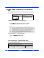
Charging the Batteries
Before using the Vista XL monitor for the first time, charge the internal battery for a
maximum of 4.5 hours and the external battery for 3.5 hours. When the monitor
receives DC power, batteries recharge automatically.
The optional SLA Battery Charger can charge four fully depleted external batteries
simultaneously in approximately 3.5 hours. To start a fast-charge, insert the batteries
into the slots of the battery charger with the metal contacts facing down.
CAUTION: This charger is intended for charging the monitor batteries only. Do not use
other chargers or batteries.
When the monitor receives DC power, batteries recharge automatically.
1-12
VISTA XL
VF7
GETTING STARTED
Getting Started
Turning the Monitor On and Off
To turn the monitor on:
z
Press the power key ('), located on the bottom left of the Vista XL
monitor's front panel . The monitor turns on the power indicator light, lights
up the screen, performs a self-test, and displays the main screen.
To turn the monitor off:
z
Press and hold the power key (O) for two seconds. The power indicator
light turns dark, and the monitor emits a power-down tone.
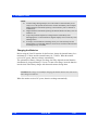
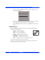
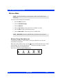
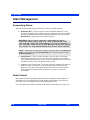
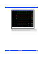
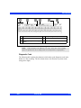
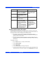
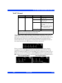
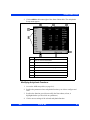
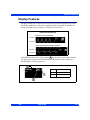
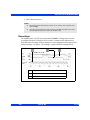
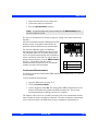
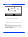
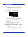
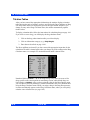
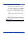
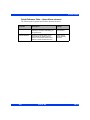
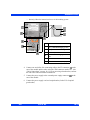
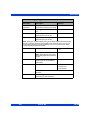
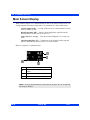
Accessing the Main Screen
After you power up the monitor, the main screen appears. To return to the main screen
from a menu or other display:
z
VF7
Press the Main Screen fixed key, located just above the rotary knob on the front
panel of the monitor. The main screen appears, as shown in the following
illustration.
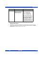
1
Network message
2
Parameter boxes
3
Waveforms
4
Local message
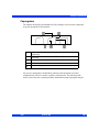
VISTA XL
1-13
1 INTRODUCTION
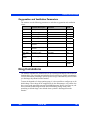
The standard monitor provides five waveform channels with adjacent parameter
boxes. Channels can be added to display up to six waveforms. The bottom channel can
be used to display additional parameter boxes (see “Bottom Channel” on page 2-7).
Parameter boxes show values, alarm limits, and special icons for selected parameters.
NOTE:
z
You can access parameter setup menus by scrolling through the parameter
boxes using the rotary knob and clicking on the parameter you wish to
configure.
z
See “Quick Reference -- Main Menu Setup” on page 2-3 to access parameter
setup menus.
Parameters and their associated waveforms are color-coded for easy recognition.
NOTE:
z
You can change the default color coding for each parameter by accessing the
Parameter Colors menu. (See page 2-19)
z
For a list of default parameter colors, see Quick Reference -- Parameter Colors
Menu on page 2-20.
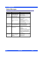
Messages appear along the top of the screen in either the Local Message (left) or
Network Message (right) area. When there is no local message, the monitor displays
the patient’s name and bed label. When there is no network message, the monitor
displays the date and time.
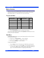
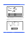
Using the Rotary Knob
The rotary knob allows you to browse menus, choose settings, and execute
menu functions. Scroll through menu items by turning the knob. Press the
knob (or click) to confirm.
To set or execute menu items with the rotary knob:
1. Select the required function by dialing the knob.
2. Press the knob and click to confirm your selection. A list of choices appears
or the field switches to its alternate value, e.g., ON to OFF.
You can also use the rotary knob to enter letters or numbers.
1-14
VISTA XL
VF7
GETTING STARTED
1. Click on a field (e.g., Physician). The monitor displays a data-entry screen
similar to the following:
2. Use the rotary knob to select each character or number, then click to confirm.
Use the control buttons at the bottom of the screen for editing.
3. Click on Accept to confirm the entire entry or on Cancel to exit the data entry
screen.
Remote Keypad
The remote keypad has all of the fixed keys that are on the monitor and additional
keys that perform the following:
Trends — Displays trend graphs
Freeze — Freezes waveform display
Calcs. — Activates Calculations menu
All ECG — Displays Show All Leads screen
Remote View — Displays Remote View menu
Recall Setup — Displays Restore Setups menu
View+ — Toggles from monitor to secondary (display) screen
To connect the remote keypad to the Vista XL monitor:
Plug one end of the keypad cable into the keypad and the other into the connector
marked RS232 on the right side of the monitor.
VF7
VISTA XL
1-15
1 INTRODUCTION
Menu Access
There are two ways of accessing the menus. The Fast Access menu allows you to open
commonly used menus quickly. The Main Menu lists the primary menus (Patient
Setup, Monitor Setup, etc.), which allow you to access other menus.
Fast Access Menu
The Fast Access menu accesses the following submenus and screens directly:
Fast Access Item
See page
Fast Access Item
See page
Remote View
3-10
Calculations
14-1
OxyCRG (Neonatal only)
11-10
Show All Leads
8-15
Alarm History
5-15
OR
2-11
Trend Graphs
6-4
Reports
7-11
Trend Table
6-7
Split Screen
2-8
Event Recall
1-19
Drug Dosage
14-7
To open the Fast Access menu:
z
Press the Fast Access fixed key on the front of the monitor.
You can access many of these menus by selecting Review on the Main Screen menu.
See page 2-4 for more information.
Main Menu
The Main Menu allows you to execute certain functions and access others. Icons are
used to identify menu items:
z
Page icon (e.g., Restore Setups) -- Accesses submenu
z
Arrow icon (e.g., Review) -- Displays another column
z
No icon (e.g., Standby) -- Executes function
To display the Main Menu:
1. Press the Menu fixed key. The primary list of Main Menu options appears.
2. Click on a page icon next to a heading ( ) to open a Main Menu submenu or
on an arrow icon (
) to display another column of Main Menu options (see
page 2-3 for detailed information on configuring the Main Menu).
1-16
VISTA XL
VF7
DATA ARCHIVE APPLICATIONS
Fixed Keys
Fixed keys on the monitor front panel allow you to perform commonly executed
functions. .
CAUTION: Moisture under the front panel can damage the electric circuits and
compromise key function. For safe cleaning instructions, see page 21-1.
Fixed
Key
Description
Fixed
Key
Description
Alarm
Silence
Silences the active alarm
tone for one minute
Main
Screen
Activates the main screen
Alarm
Limits
Opens a table from which
you can set upper and lower
alarm limits
Menu
Activates the Main Menu
All
Alarms
Off
Suspends all alarms for a
pre-selected time or cancels
the suspension
NBP
Start
Stop
Starts or stops non-invasive
blood pressure (NBP)
measurement
Fast
Access
Displays the Fast Access
Menu
Record
Toggles a timed recording
on or off
Control Buttons
Control buttons are located along the bottom of the various screens, trend tables,
graphs, loop displays, etc. They permit additional screen-specific settings.
Data Archive Applications
The monitor can store events, alarms and trends automatically or at the user’s request,
depending on the type of information you wish to store. Some events are
automatically recorded and stored. The monitor automatically stores alarm conditions
and arrhythmia events that you have configured for storage in the Alarm Limits table
(see page 5-5) and in the Arrhythmia setup table (see page 9-6).
NOTE: You cannot disable event storage for asystole and ventricular fibrillation calls.
The monitor stores these events automatically.
You can access archived information in one or more of the following databases:
z
VF7
Trends
VISTA XL
1-17
1 INTRODUCTION
z
Calculations
z
Alarm History
z
Event Recall.
Each database indicates the time of the data capture and parameter values and/or
waveforms active at the time of capture. Trends, Calculations, and Alarm History are
discussed in the following chapters (Event Recall and Storage is explained later in this
section.):
z
Trends -- See Chapter 6, Trends. Stored events are marked with the time and
date of capture as follows:
Trend Table -- An icon (
) over the time line marks manually stored events
only. (Automatically stored alarms and arrhythmia calls are not marked in the
Trend Table.)
Trend Graphs -- A small yellow vertical line at the top of the screen marks
manually and automatically stored events.
z
Calculations -- See Chapter 14, Calculations.
z
Alarm History -- See Chapter 5, Alarms.
Storing Events
Automatic Storage
The monitor stores events automatically, if you have first correctly configured the
Alarm Limits and Arrhythmia Setup tables.
You can enable individual parameter alarms in the Alarms column of the Alarm
Limits and/or the ARR Setup screens. Configure event storage in the Archive column
by selecting Store or Str./Rec.
1-18
VISTA XL
VF7
DATA ARCHIVE APPLICATIONS
Event Recall
The monitor stores monitoring data (waveforms and parameter values), alarm
conditions, and arrhythmia events on the Event Recall screen. You can view up to 50
stored events, each containing 20 seconds of data, with associated date and time
stamps.
Events are stored on a first-in, first-out basis. When event storage is full, the monitor
deletes the oldest events to make room for new ones. All stored events are deleted
whenever you discharge a patient, reset the monitor, or temporarily lose power.
To access the Event Recall screen:
1. Press the Fast Access fixed key.
2. Click on Event Recall to display the Event Recall screen.
VF7
VISTA XL
1-19
1 INTRODUCTION
1-20
1
Time of capture
2
Parameter values at time of capture
3
Print report
4
Requests recording
5
Saves/Deletes events
6
View: All - displays all stored events; Manual - displays manually
stored events; Alarm - displays alarm events only; BRDY - displays
bradycardia events only; Desat - (Neonatal only) displays desaturation
events only
7
Parameter display: Prev displays previous set of (2) parameters.
Next displays next set of (2) parameters
8
Parameter labels of displayed waveforms
9
Waveform delay and speed
VISTA XL
VF7
DATA ARCHIVE APPLICATIONS
Navigating the Event Recall Screen
To scroll forward and back through 20 seconds of waveform data, click on arrows at
either side of scroll bar at the bottom of the screen.
To scroll through the list of parameter values at the time of data capture, click on the
arrow keys above the list of parameters at the right of the screen:
To scroll through the waveforms displayed at the time of data capture, click on the
Prev (Previous) and Next control buttons under waveform display.
VF7
VISTA XL
1-21
1 INTRODUCTION
Help Functions
You can display a short description of currently highlighted functions at the bottom of
all active menus by enabling context-sensitive help:
1. Press the Menu fixed key to open the Main Menu.
2. Click on Monitor Setup. Another column of options appears.
3. Open the Display Options menu by clicking on that heading.
4. Select Help Line Display and click to choose ON.
Additional information about the monitor is available in the Main Help menu.
1. Press the Menu fixed key.
2. Click on Help. The Main Help Menu appears.
Click on the appropriate selection in the table below.
Menu Item
Description
Locked Options
Displays active software options currently installed on the
monitor
Fixed Keys
Describes functions of Fixed Keys
1-22
VISTA XL
VF7
Chapter 2 Monitor Setup
Overview............................................................................................................................2
Configuring the Monitor...................................................................................................2
Main Menu Setup........................................................................................................2
Quick Reference -- Main Menu Setup .......................................................................3
Setups Management.......................................................................................................10
Specialty Menus..............................................................................................................11
OR Mode ...................................................................................................................11
Unit Manager ............................................................................................................13
Biomed ......................................................................................................................17
Parameter Colors .....................................................................................................19
2 MONITOR SETUP
Overview
This chapter describes how to configure the monitor.
Configuring the Monitor
Main Menu Setup
The Main Menu allows you to access submenus, display screens, and execute certain
monitor setup functions.
1. Press the Menu fixed key to display the Main Menu.
2. Click on a page icon (
or
Click on arrow icon (
) to open a Main Menu submenu,
) to display another column of submenu options.
3. Click on desired setting to execute functions or access further submenus.
4. Click on Exit at the bottom of a submenu list or on the white arrow in upper
left corner of the screen to return to prior menu or screen.
2-2
VISTA XL
VF7
CONFIGURING THE MONITOR
Quick Reference -- Main Menu Setup
The Main Menu
Menu Item
Description
Available Settings
Cursor Tool
Provides access to Cursor Tool
submenu, which allows user to
select three waveforms
displayed with horizontal cursors
and a vertical cursor.
•
•
•
•
•
Setup
Horizontal Cursor
Stop
Hemo/Calcs
Vertical Cursor
Note: See Cursor Tool Submenu,
below.
The Cursor Tool Submenu
This submenu allows you access to the following functions.
Setup
Opens Cursor Tool Setup menu.
• Waveform (Up to 3.)
NOTE: In 4 channel mode, maximum of
2 waveforms.
•
•
•
•
•
Horizontal
Cursor
(One for each
waveform on
display)
Displays a horizontal cursor.
User can scroll up and down
each waveform.
NOTES:
• Cursor value is displayed1.
• Cursor and value are on display
until user exits window.
• Buttons remain ghosted until
user presses Stop key.
To EXIT the Cursor tool:
• Press/click the Rotary Knob to
exit cursor control.
or
• Press the Main Screen fixed
key.
Sweep Speed
6.25 mm/sec.
12.5 mm/sec.
25 mm/sec. (Default)
50 mm/sec.
N/A
1
Cursor value is displayed only if a scale is associated with the waveform.
Waveform scales are the same as parameter main display.
Stop
VF7
Halts scrolling of all waveforms in
cursor tool display and un-ghosts
Horizontal and Vertical Cursor
buttons.
VISTA XL
N/A
2-3
2 MONITOR SETUP
The Main Menu
Menu Item
Description
Available Settings
Hemo/Calcs
Opens the hemo/calcs screen.
NOTES:
• Button is ghosted unless a
license is present.
• Advanced calcs menu is
available if option is installed.
N/A
Vertical
Cursor
Displays a vertical cursor. User
can scroll forward and backward
across all waveforms.
NOTES:
• Cursor has no value.
• Cursor remains on display until
user exits window.
• Buttons remain ghosted until
user presses Stop key.
To EXIT the Cursor tool:
• Press/click the Rotary Knob to
exit cursor control.
or
• Press the Menu, Main Screen,
Alarm Limits, or Fast Access
fixed key.
N/A
Review
Provides access to submenus of
the Main Menu display
• Click on Review to open the
following submenus and
displays: Alarm History, Trend
Graphs, Trend Table, Event
Recall, Calc. Results,
OxyCRG (neonatal mode
only), Show All Leads, and
Reports.
• Click on Exit to return to the
first column of the Main Menu.
2-4
VISTA XL
VF7
CONFIGURING THE MONITOR
The Main Menu
Menu Item
Description
Available Settings
The Patient Setup Submenu
This submenu allows you to configure the following functions.
Patient
Category
Determines availability of
monitoring features such as
apnea detection (neonates only)
and ventilation
• Adult
• Pediatric
• Neonatal
Notes:
• When you click on a setting, a
popup message warns you that
algorithms and alarm settings
are about to change. In the
popup window, click again on
the category of your choice.
• If you change a patient’s
category, the weight selection
is cleared and must be selected
again.
Pressure
Labels
Assigns IBP pressure channel
labels
See Chapter 13, Invasive Blood
Pressure, for detailed
information.
ART, PA, CVP, LA, LV, RV, RA,
ICP, GP1, GP2
Parameters
Accesses parameters’ setup
menus
• Click on one of the listed
parameters to access its setup
menu: (e.g., ECG, ARR, ST,
ART, PA CVP, RA, SpO2, NBP,
RESP, etCO2, C.O., TEMP,
GP1, GP2, O2, fiO2, ).
Note: There may be other
possible selections depending
on the monitor configuration and
connected devices.
• Click on Exit to return to the
first column of the Main Menu.
Alarm Limits
Opens alarm limits table
N/A; see page 5-5.
VF7
VISTA XL
2-5
2 MONITOR SETUP
The Main Menu
Menu Item
Description
Available Settings
The Monitor Setup Submenu
Main Screen
This submenu allows you to lay out the main screen display by configuring the
functions outlined below. To access second page of the Main Screen menu, click on
the down arrow at the bottom of the screen. Click on the up arrow to return to the
Main Screen menu first page.
Parameter
Priority
Allows you to modify the order of
parameters displayed on the
Main Screen
Notes:
• Parameters must be assigned
a priority; whether they appear
on the main screen depends on
their priority and on the number
of channels configured to
display waveforms (see Max.
Channels).
• In Automatic display mode,
connected parameters are
displayed according to their
priority in the Parameter
Priority list. If all available
channels are filled, a higher
priority parameter will NOT
“bump” lower priority parameter
boxes off the Main Screen
when the associated device is
connected. In order to display
the parameter, the user must
double-click on the parameter
in the Parameter Priority list.
• In OR Mode, if all available
channels are filled, a higher
priority parameter will “bump”
lower priority parameter boxes
off the Main Screen when the
associated device is
connected.
To change the display order of a
parameter whether or not the
associated device is connected:
1) Scroll to Display Mode.
2) Select Manual.
3) Click on Parameter Priority
to highlight the first listed
parameter.
Note: Parameters are
numbered according to their
priority. The display is color
coded: A green parameter label
indicates that the associated
parameter device (e.g., an NBP
hose/cuff) is connected to the
monitor. A white label indicates
that the device is not connected.
4) Scroll the list to the
parameter you wish to move
and click.
5) Move the parameter to its
new place using the rotary knob.
6) Click to confirm the
parameter’s new position on the
list.
7) Click again to return to
Parameter Priority.
8) Scroll to the arrow at the
upper left corner of the menu to
exit, or continue to set up other
Main Screen submenu
functions.
Max.
Channels
Determines number of waveform
channels and parameters
displayed
• Click on 4, 5, 6, 7, or 8.
Note: The number of
waveforms you can display
depends on the software option
you have installed.
2-6
VISTA XL
VF7
CONFIGURING THE MONITOR
The Main Menu
Menu Item
Description
Available Settings
Bottom
Channel
Configures bottom waveform
channel to display waveform or
parameter boxes
• Click on Waveform to display
a waveform in the bottom
channel.
• Click on Parameters to
display 3 parameter boxes
instead of a waveform in the
bottom channel.
ECG
Channels
Determines the number and
format of ECG waveforms
displayed
Click on the following settings:
• ECG1 -- Displays the primary
ECG signal
• ECG1 & 2 -- Displays 2
signals
• ECG1 & 2 & 3 -- Displays 3
signals
• Cascade -- Cascades ECG1
data into second channel
ARR
Monitoring
Selects the Arrhythmia mode
(For detailed information, see
page 9-1.)
• Click on OFF to disable
arrhythmia monitoring.
• Click on FULL to enable full
arrhythmia monitoring.
• Click on BASIC to enable
basic arrhythmia monitoring.
ST Monitoring
Enables and disables ST
Monitoring (For detailed
information, refer to Chapter 10,
ST Monitoring.)
• Select ON to enable ST
monitoring.
• Select OFF to disable ST
monitoring.
RESP
Monitoring
Enables and disables respiration
monitoring
(For detailed information, refer to
Chapter 11, Respiration.)
• Select ON to enable
respiration monitoring.
• Select OFF to disable
respiration monitoring.
Display Mode
Reduces Main Screen clutter by • Click on Manual to display all
displaying only parameters
parameters and assign them a
associated with a connected
priority on the Parameter
device
Priority screen.
(see Parameter Priority, page 2- • Click on Automatic to display
6)
active parameters only.
VF7
VISTA XL
2-7
2 MONITOR SETUP
The Main Menu
Menu Item
Description
Available Settings
Split Screen
Reserves a portion of the main
screen for display of trend
graphs
Click on one of the following:
• OFF
• 60 Min Trends
• 10 Min Trends
Display Options
This submenu allows you to access and modify waveforms and other display
features
by configuring the following functions.
Monitoring
Sweep Speed
Determines waveform speed
Higher sweep speed “moves”
waveform more quickly.
• Click on 6.25, 12.5, 25, or 50
mm/s.
Respiratory
Sweep Speed
Allows you to set monitoring
sweep speed for Respiration
waveform independently
• Click on 6.25, 12.5, 25, or 50
mm/s.
Pressure
Overlap
Displays up to 4 overlapping IBP
waveforms in single oversized
channel
Overlapped waveforms share a
common zero point, but each
retains original scale
configuration (see page 13-11).
• Select ON to display IBP
waveforms in overlapping
format.
• Select OFF to cancel display
of waveforms in overlapping
format.
Pressure
Common
Scale
Displays pressure waveforms
with a common scale, making it
easier to compare them
• Click on 5, 10, 15, 20, 25, 30,
40, 50, 75, 100, 150, 200, 250,
300 mmHg, or OFF.
Monitor
Brightness
Sets brightness of monitor
• Click on Auto (ambient light),
20, 40, 60, 80, or 100%.
SC 9015
Brightness
Sets brightness of SC 9015
Help Line
Display
Shows contextual help line at
bottom of menu
• Select ON to display help.
• Select OFF to cancel display.
Parameter
Units Display
Displays unit of measure in
parameter boxes
• Select ON to display units.
• Select OFF to cancel display.
2-8
VISTA XL
VF7
CONFIGURING THE MONITOR
The Main Menu
Menu Item
Description
Available Settings
Monitor Options
This submenu allows you to configure the following functions.
Date & Time
Sets the date and time displayed
in the lower right potion of the
main screen
Notes:
• An internal battery powers the
monitor’s clock even when the
monitor is turned off.
• This option is not available
when the monitor is connected
to network, since network date
and time are set at the central
station.
• Changing the time does not
affect other time-related
functions such as timers and
time stamps.
To set the monitor date and
time:
1) Click on Date & Time.
2) Click on Current Date. A
data entry screen appears.
3) Click on Day, scroll to the
correct date, and click.
4) Repeat Step 3 for Month and
Year.
5) Click on Accept to confirm or
on Cancel to return to
submenu.
6) Click on Current Time to set
the time, using the same
method described in steps 3
and 5.
Speaker
Volumes
Allows you to set the volume for
alarms, pulse tones, and
attention tones
• Click on Alarm Volume to set
the volume of alarms (10100% in increments of 10).
• Click on Pulse Tone Volume to
set the volume of the pulse
tone (OFF-100% in increments
of 10 after 5).
• Click on Attention Tone
Volume to set the volume of
attention tones (OFF-100% in
increments of 10 after 5).
Trend Setup
Allows you to configure trend
display
• Submenu; see Chapter 6,
Trends, for detailed
information.
Recordings
Allows you to configure and
assign recorders
• Submenu; see Chapter 7,
Recordings, for information.
Biomed
Provides access to technical and
clinical logs and service menus
• Submenu; see page 2-17.
Unit Manager
Allows the unit manager,
physician or head nurse to
configure monitoring functions
for the clinical staff
• Submenu; see page 2-13.
OR
Configures monitor to meet the
special needs of the operating
room environment
• Submenu; see page 2-11.
VF7
VISTA XL
2-9
2 MONITOR SETUP
Setups Management
You can save and restore the current patient and monitoring settings.
Setups Management
Menu function/
item
Description
Reference/Procedures
Configuring Setups
To save, or restore setups, configure them as shown in the referenced pages.
Main screen display
Main Screen menu
Page 2-6
Parameters
Parameter Setup menu(s)
Page 2-5
Note: For more information,
see parameter chapters.
Alarms
Alarm Limits Table
Page 5-5
Arrhythmia calls
Arrhythmia Setup Table
Page 9-6
Trends
Trend Setup
Trend Graphs
Trend Table
Page 6-2
Page 6-4
Page 6-7
Naming and Renaming Setups
Follow these procedures to name or rename the setups you have configured.
Accessing
the Unit Manager
Menu
Allows you to modify setups
on the password-protected
Unit Manager menu
Note: For information on
other Unit Manager
functions, see page 2-13.
To enter the password:
1) Press the Menu fixed key to
display the Main Menu.
2) Click on Monitor Setup.
3) Click on Unit Manager. A
data entry box appears.
4) Click on each number of the
appropriate password. If you
make a mistake, click on
Backspace and try again.
5) Click on Accept to open the
Unit Manager menu.
Restoring Factory Defaults
Consult your Biomed to restore settings shipped with the monitor to their original
configuration. For detailed information on password-protected Biomed setup
functions,
please consult service and installation documentation.
2-10
VISTA XL
VF7
SPECIALTY MENUS
Specialty Menus
OR Mode
OR mode is designed specifically for the operating room environment, allowing you
instant access to a particular set of parameters and functions. In addition, you can
disable audible alarms without affecting visual alarms, even when the monitor is not
connected to a network.
WA R N I N G : D o n o t s e t m o n i t o r t o O R m o d e o u ts i d e o p e r a t i n g
room environment because OR alarms behave differently than
r e g u l a r a l a r ms .
NOTE:
Life Threatening and Serious alarms do not latch when OR mode is ON.
To access the OR menu:
1. Press the Fast Access fixed key.
2. Click on OR to display the OR menu.
Quick Reference Table -- OR Menu
OR Function
Description
Settings
Activates OR menu
functions
• ON -- OR functions are
enabled.
• OFF -- The monitor reverts to
normal functions;
Cardiac Bypass, and NBP
Chime are ghosted.
The OR Menu
OR
Note: This function is a locked
option. It is installed at the
time of purchase from
perioperative care unit or it
can be installed locally by
Dräger Service or local
Biomed.
Cardiac Bypass
VF7
Configures monitor for use
during cardiac surgery
VISTA XL
• ON -- Suspends all patientmonitoring alarms, NBP
interval measurements, and
arrhythmia detection.
• OFF -- The monitor reverts to
normal functions.
2-11
2 MONITOR SETUP
OR Function
Description
Settings
NBP Chime
Enables and disables
attention tone for NBP
measurements
(For more information, see
Chapter 12, Non-Invasive
Blood Pressure.)
• ON -- Monitor sounds an
attention tone when NBP
measurement is complete.
• OFF -- No tone sounds when
you complete an NBP
measurement.
Alarm Volume
Sets alarm volume
Note: Minimum setting is
OFF if OR is enabled or if
monitor is connected to a
central station. Minimum
setting is 10% if OR is
disabled.
• 20 - 100% in increments of 10
• OFF or 10%
Large IBP-Mean
Display
Determines the relative size
of the mean pressure value
in invasive pressure
parameter boxes
• ON -- Enlarges mean IBP
display
• OFF -- Reduces mean IBP
display to match systolic and
diastolic display size
Attention Tone
Volume
Sets attention tone volume
Notes:
• Minimum setting is 5% if
OR is enabled or if monitor
is connected to a central
station. Minimum setting is
10% if OR is disabled.
• 20 - 100% in increments of 10
• OFF or 5%
HR Source
Derives heart rate from
various sources
Click on one of the following
settings to determine the Heart
Rate source:
• ECG
• ART
• SpO2
• AUTO
Note: This function is useful
during electrosurgery, when
artifact makes ECG channel
unavailable. See page 8-20
for more information.
Filter
Determines sensitivity to
noise, artifact, and other
signal distortion
Note: The ESU setting
automatically disables pacer
detection. See page 8-17 for
detailed information on
Filter and its settings.
• OFF
• ESU
• Monitor
ARR Monitoring
Determines number of
arrhythmia events you can
monitor
Note: For detailed
information, see page 9-1.
• OFF
• Basic
• Full
Pulse Tone
Volume
Sets pulse tone volume
(See page 2-9.)
• Off - 100%
2-12
VISTA XL
VF7
SPECIALTY MENUS
Unit Manager
The Unit Manager menu lets supervisory personnel configure monitoring functions
for the clinical staff. Access to this menu is restricted by a password. To open the Unit
Manager menu:
1. Press the Menu fixed key to open the Main Menu.
2. Click on Monitor Setup.
3. Click on Unit Manager. A data entry box appears.
4. Scroll through the numbers and click successively on the single digits of the
clinical password. If you make a mistake, click on Backspace and try again.
5. Click on Accept to open the Unit Manager menu. Available functions are
described in the table that follows.
The Unit Manager Menu
Menu Item
Description
Available Settings
The Alarm Control Submenu
This menu allows the unit manager to configure alarm annunciation. Open the Unit
Manager menu, click on Alarm Control, then follow the procedures outlined in this
table to execute the indicated functions.
All Alarms OFF
Key
Determines whether clinical
personnel can suspend alarms
by using the All Alarms Off
fixed key on the front of the
monitor
• ON -- Pressing All Alarms Off
fixed key suspends alarms.
• OFF -- Pressing All Alarms
Off fixed key triggers an error
tone.
All Alarms OFF
Time
Sets alarm suspension time
• 1, 2, 3, 4, or 5 min -- A timer at
the top of the screen indicates
WARNING: Never leave
a patient unattended during
an indefinite alarm
suspension (e.g., after
selecting No Timeout).
Always enable the alarms
again as soon as possible.
Extend All
Alarms OFF
Note: This
selection will only
appear if monitor
is configured to
support this
feature. Contact
your biomed for
more information.
VF7
Determines whether clinical
personnel can use the All
Alarms Off fixed key to extend
the All Alarms Off time.
VISTA XL
the amount of time
remaining in All Alarms
OFF Time.
• No Timeout -- Alarms
suspended indefinitely; no
timer appears.
• Enabled
• Disabled (default)
2-13
2 MONITOR SETUP
The Unit Manager Menu
Menu Item
Description
Available Settings
Alarm
Validation
Note: When
Validates alarm conditions to
limit nuisance alarms due to
artifact or motion/movement by
delaying time to alarm.
Alarm validation times are:
Upper
Lower
HR
6 sec.
6 sec.
RESP
14 sec. 14 sec.
IBP
4 sec.
10 sec.
6 sec.
10 sec.1
SpO2
PLS
6 sec.
10 sec.1
SpO2*
4 sec.
4 sec.
PLS*
4 sec.
immediately
All Other Parameters
immediately
1(See “SpO2 Alarm Delay”.)
• ON -- Enables Alarm
Validation
Validates an SpO2 alarm
condition by requiring that
violation persist for 10 seconds
(lower limit) before sounding an
alarm.
Note: Alarm validation must be
turned ON.
• ON -- SpO2 or PLS lower limit
alarm condition annunciated
after it persists for a period of
10 seconds.
• OFF -- SpO2 or PLS lower limit
alarm condition is not validated
before annunciation.
ASY/VF Alarms Allows user to prevent disabling
• Always ON -- ASY and VFIB
alarms are always active.
• Follow HR Alarms (default) -ASY and VFIB alarms follow
HR alarm settings.
Alarm Validation
is ON, the time to
alarm from the
onset of a limit
violation will equal
the time for
detection + the
designated Alarm
Validation signal
delay. For HR,
this time may
exceed AAMI
EC13 requirement
of a maximum of
10 seconds.
SpO2 Alarm
Delay
of ASY and VFIB alarms.
• OFF -- Disables Alarm
Validation
WARNING: When HR
Alarm is “OFF” and ARR
monitoring is “OFF”,
ASY/VF alarms do not
sound.
NBP/SpO2
Interlock
Allows user to render SpO2
alarm inactive when NIBP
measurement is in progress.
WARNING: Visually
ensure that NIBP cuff is
on the same arm as SPO2
sensor. The monitor will
not automatically detect
that NIBP cuff and SPO2
sensor are on the same arm.
2-14
• ON -- SpO2 alarm is inactive
when NBP measurement is
taken.
• OFF (default) -- SpO2 alarm is
active when NBP
measurement is taken.
VISTA XL
VF7
SPECIALTY MENUS
The Unit Manager Menu
Menu Item
Description
Available Settings
MIB Alarm
Control
Allows user to activate/
deactivate MIB disconnect
alarm.
• ON (default) -- MIB disconnect
alarms are active.
• OFF -- MIB disconnect alarms
are inactive.
Remote View
Display
Allows user to set Remote View
behavior when Remote View is
displaying telemetry ECG.
• Always ON -- Local bed alarm
will not cause remote view
feature to “pull down” remote
bed display.
• Pull Down on Alarm (default)
-- Local bed alarm will cause
remote view feature to “pull
down” remote bed display.
Audio Alarm
Reminder
Allows user to set a reminder
when alarm volume is turned
OFF.
• ON (default) -- When Alarm
Volume is turned OFF, a
reminder tone sounds every 30
sec. at 50% volume.
Note: For OR Mode: at the end of
the countdown period (alarm
silence or alarm off), if the
alarm condition is still active,
the parameter box will flash
and an appropriate SER, LT,
or ADV reminder tone (at
50% volume) sounds every
30 sec.
• OFF -- There is no reminder
tone when Alarm Volume is
turned OFF.
SpO2 Alarm
Delay
Validates an SpO2 alarm
condition by requiring that
violation persist for 10 seconds
(lower limit) before sounding
an alarm.
Note: Alarm validation must be
turned ON.
• ON -- SpO2 or PLS lower limit
alarm condition annunciated
after it persists for a period of
10 seconds.
• OFF -- SpO2 or PLS lower limit
alarm condition is not validated
before annunciation.
The Code Setup Submenu
This menu allows the unit manager to configure the monitor for quick emergency
response. Open the Unit Manager menu (page 2-13), click on Code Setup, then
select and execute functions as described in this table. For more information, see
page 5-4.
Continuous
Record
VF7
Note: If no recorder is
available, the recording
request remains pending for
later printing. The default
setting is Yes.
VISTA XL
• Yes -- Allows continuous
recording when you press the
Code key on the remote
keypad.
• No -- No recording can be
initiated when Code key is
pressed.
2-15
2 MONITOR SETUP
The Unit Manager Menu
Menu Item
Description
Available Settings
Continuous
NBP
Note: You must attach the
NBP cuff and display the NBP
parameter box before
requesting NBP
measurements. The default
setting is No.
• Yes -- Allows continuous NBP
measurements when you
press the Code key on the
remote keypad.
• No -- No NBP measurements
can be initiated when Code
key is pressed.
Alarm Volume
OFF
The default setting is No.
• Yes -- Allows you to lower the
alarm volume (to 10% on nonnetworked monitors) or silence
alarms completely (OFF on
networked monitors) when you
press the Code key on the
remote keypad.
• No -- Alarm volumes are not
affected when the Code key
on the remote keypad is
pressed.
The Menu Setup Submenu
Menu Setup
Determines amount of time
menus and screens remain
displayed
Note: This setting determines
menu display time in Remote
View also.
1) Click on Menu Setup.
2) Click on Menu Time Limit.
3) Click on one of the following:
• ON -- Active menus and
screens display for a limited
time only (approximately 5
minutes).
• OFF -- Menus and screens
remain displayed until you
cancel them or select another
display.
The Drug List Setup Submenu
This menu allows the unit manager to store up to 44 types of drugs and their
dosages for use during drug calculations. Open the Unit Manager menu (page 2-13),
click on Drug Setup, then follow the procedures outlined on page 14-9.
2-16
VISTA XL
VF7
SPECIALTY MENUS
The Unit Manager Menu
Menu Item
Description
Available Settings
The Change Password Submenu
This feature allows you to change the password of the Unit Manager menu.
Open the Unit Manager menu (page 2-13), click on Change Password, then follow
the procedures outlined in this table.
1) Scroll through the numbers and click successively on the single digits of the
clinical password. If you make a mistake, click on Backspace and try again.
2) Click on Accept to confirm the new password.
The Pacer Detection Mode Submenu
This feature allows you to set pacer detection function.
Open the Unit Manager menu, click on Pacer Detection Mode, then follow the
procedures outlined in this table.
Basic (default)
Sets Pacer Detection selections
in the ECG options submenu to
ON/OFF only.
• N/A
Advanced
Sets Pacer Detection
selections in the ECG options
submenu to ON/OFF/Fusion.
• N/A
Biomed
The Biomed menu addresses technical aspects of the monitor. To open the Biomed
menu:
1. Press the Menu fixed key to open the Main Menu.
2. Click on Monitor Setup.
3. Click on Biomed.
Quick Reference -- Biomed Menu
Menu Item
Description
Settings/Procedures
The Logs Submenu
This menu displays clinical and technical diagnostic records. Open the Biomed
menu and click on Logs, then follow the procedures described in this table.
VF7
VISTA XL
2-17
2 MONITOR SETUP
Menu Item
Description
Settings/Procedures
Component Log
The monitor maintains readonly logs for principal
components or devices.
These logs include a part
and revision numbers, serial
numbers, software version,
and compatibility
information.
1) Scroll to the component
you wish to inspect and click
on it. The log appears with
the exit arrow already
selected.
2) Return to the Logs
submenu by clicking again.
Status Log
Displays information about
your current software and
hardware versions
Display is read-only.
Diagnostic Log
Captures data about
hardware and software
performance relating to the
monitor’s operation
Display is read-only.
• Click on the down arrow at
the bottom of screen to
scroll through the display.
FE Diag. Log
Captures and displays data
about front-end performance
related to the monitor’s
operation
Display is read-only.
• Click on the down arrow at
the bottom of screen to
scroll through the display.
Copy All Logs
Downloads status logs and
diagnostic logs to a memory
card
Click on Copy All Logs. A
confirmation message
appears in the message
area to indicate the
download is complete.
Print Log
Prints an expanded version
of the Diagnostic Log to an
INFINITY network laser printer
Click on Print Log.
The Service Submenu
The Service menu is password-protected
and intended for the hospital’s biomedical or Dräger Medical service personnel
only.
Test Pulse
Test Pulse
2-18
Tests ECG signal clarity and
display
Clicking on Test Pulse:
• Injects a 300 ms pulse into
the ECG waveform (1 mV
on leads I and III, 2 mV on
lead II).
VISTA XL
VF7
SPECIALTY MENUS
Parameter Colors
The Parameter Colors menu allows the user to assign a color to an individual
parameter/waveform. To open the Parameter Colors menu:
1. Press the Menu fixed key to open the Main Menu.
2. Click on Monitor Setup.
3. Click on Monitor Options.
4. Click on Parameter Colors.
5. Enter clinical password.
NOTE: The clinical password menu will time-out after approximately 5 minutes . It
will stay active that long unless the user clicks Accept.
6. Click on Accept.
7. Click on parameter and select color desired.
8. Click on desired color.
Parameter Colors functions are described in the following table:
VF7
VISTA XL
2-19
2 MONITOR SETUP
Quick Reference -- Parameter Colors Menu
Default
Color
Parameter
Possible Selections
NOTES:
• The color change set in this menu changes all uses of the parameter
(parameter-box, waveform, trends).
• The parameter list is not limited to only parameters connected.
• Agent parameters (HAL, ISO, ENF, SEV, DES) and O2/N2O cannot change
color.
2-20
ECG (inc. ST, ARR)
Notes:
• ECG lead label on Main Screen is
same color as waveform.
• ST complexes follow the color
selected for ECG (Reference curves
remain purple)
Green
Red, White, Yellow, Green,
Lt. Blue, Blue, Purple,
Orange
ART
Red
Red, White, Yellow, Green,
Lt. Blue, Blue, Purple,
Orange
PA
Yellow
Red, White, Yellow, Green,
Lt. Blue, Blue, Purple,
Orange
CVP
Lt. Blue
Red, White, Yellow, Green,
Lt. Blue, Blue, Purple,
Orange
RA
Orange
Red, White, Yellow, Green,
Lt. Blue, Blue, Purple,
Orange
LA
Purple
Red, White, Yellow, Green,
Lt. Blue, Blue, Purple,
Orange
LV
Yellow
Red, White, Yellow, Green,
Lt. Blue, Blue, Purple,
Orange
ICP
Lt.Blue
Red, White, Yellow, Green,
Lt. Blue, Blue, Purple,
Orange
RV
Orange
Red, White, Yellow, Green,
Lt. Blue, Blue, Purple,
Orange
GP1 and/or GP2
Red
Red, White, Yellow, Green,
Lt. Blue, Blue, Purple,
Orange
VISTA XL
VF7
SPECIALTY MENUS
VF7
Parameter
Default
Color
Possible Selections
P1a and/or P1b and/or P1c and/or
P1d
Red
Red, White, Yellow, Green,
Lt. Blue, Blue, Purple,
Orange
P2a and/or P2b and/or P2c and/or
P2d
Red
Red, White, Yellow, Green,
Lt. Blue, Blue, Purple,
Orange
P3a and/or P3b and/or P3c and/or
P3d
Red
Red, White, Yellow, Green,
Lt. Blue, Blue, Purple,
Orange
TEMP
White
Red, White, Yellow, Green,
Lt. Blue, Blue, Purple,
Orange
EtCO2 (inc. iCO2, RRc) and/or
EtCO2* (inc. iCO2*, RRc*)
Yellow
Red, White, Yellow, Green,
Lt. Blue, Blue, Purple,
Orange
SpO2 (inc. PLS) and/or SpO2* (no
waveform, but inc. PLS*, Δ SpO2%)
White
Red, White, Yellow, Green,
Lt. Blue, Blue, Purple,
Orange
NBP
Note: During NBP measurement,
NBP p-box becomes white
background with black letters/
numerics regardless of color selected
in this menu.
White
Red, White, Yellow, Green,
Lt. Blue, Blue, Purple,
Orange
RESP
Blue
Red, White, Yellow, Green,
Lt. Blue, Blue, Purple,
Orange
O2/N2O
White
None
FiO2
White
Red, White, Yellow, Green,
Lt. Blue, Blue, Purple,
Orange
VISTA XL
2-21
2 MONITOR SETUP
- This page intentionally left blank -
2-22
VISTA XL
VF7
Chapter 3 Network Applications
Overview............................................................................................................................2
Connecting to the Network ..............................................................................................3
Connecting the Vista XL to the Network ..................................................................3
Network Message .......................................................................................................3
Disconnecting the Vista XL from the Network ........................................................3
Wireless Network..............................................................................................................4
Wireless Network Safety Considerations ................................................................4
Wireless Network Setup ............................................................................................5
Wireless Mode ...........................................................................................................6
Wireless Messages ....................................................................................................7
Network Transfer ..............................................................................................................9
Patient Data ................................................................................................................9
Software Licenses......................................................................................................9
Remote View ...................................................................................................................10
Privacy .............................................................................................................................14
3 NETWORK APPLICATIONS
Overview
By connecting your bedside monitor to a network, you can access a patient’s
information from any other networked monitor or from a central workstation. Each of
these devices can present Main Screen information for remote viewing.
The Infinity Network‘ links monitors and other devices to a central station and to each
other, providing a wide range of monitoring functions. On the MultiView‘ you can
display information from up to 16 networked monitors simultaneously. (For more
information on the central station, see the Infinity CentralStation Instructions for Use.)
WA R N I N G : L o s s o f c o m m u n i c a t i o n b e t w e e n t h e I n f i n i t y
C e n t r a l Sta t i o n a n d t h e b e d s i d e mo nito r is p os s i b l e . D r ä g e r
r e c o m m e n d s u s i n g t h e b e d s i d e m o n i t o r f o r p ri m a r y d i a g n o s i s
a n d t h e I n f i n i t y C e n t r a l Sta t i o n f o r pa t i e n t v i e w i n g .
The DirectNet feature allows you to connect your monitor directly to the Infinity
network (see page 3-3).
Your monitor’s RemoteView‘ function allows you to display other networked monitor
screens, print remote recordings, and silence remote alarms (see page 3-10). Via the
Remote Control function on the MultiView, you can perform the following tasks at the
central station for any bedside monitor:
z
Initiate recordings
z
Modify alarm limits
z
Silence alarms
z
Initiate an Arrhythmia or Respiration Relearn
z
Print the current monitor screen on a network laser printer (via the optional
Remote Keypad)
Enter, edit, and view patient data
WA R N I N G : N e v e r r e l y o n t h e c e n t r a l s ta t i o n t o e v a lu a t e a
pa t i e n t . A l w a y s c h e c k pa t i e n t s ta t u s a t b e d s i d e .
3-2
VISTA XL
VF7
CONNECTING TO THE NETWORK
Connecting to the Network
Connecting the monitor to the network gives you access to the following:
z
Infinity network
z
Bedside recorder
z
Nurse call alarm
Connecting the Vista XL to the Network
For the Vista XL, you can connect to the network via the network connector on the
right side of the monitor.
1
Network connector
Network Message
Once the monitor is connnected to the Network, the following message may appear.
Message
Condition
Display Area
Not monitored
by central
• Connected to network, but not
assigned to an Infinity
CentralStation
Network
Disconnecting the Vista XL from the Network
To disconnect the monitor from the network, remove the cable from the network
connector in the right side of the monitor.
VF7
VISTA XL
3-3
3 NETWORK APPLICATIONS
Wireless Network
The Vista XL can operate in a wireless network which allows the monitor to establish
and maintain contact with the Infinity network and the central station without being
connected by cable.
A wireless monitor transmits and receives data with the help of a wireless LAN PC
card installed in the Memory Card slot on the monitor. The wireless card
communicates with access points which are strategically placed within a monitoring
unit in order to cover the desired transmission area.
NOTE: Wireless networking is a locked option. Contact your biomed for more
information.
A wireless network offers the following:
z
Seamless Patient Relocation — Patient and monitor can be moved to a
different room or care unit, within the same monitoring unit, without ever
losing contact with the Infinity network.
z
Simplified Network Setup — Wireless monitors can be networked without
the need of hard-wired hub connectors, which reduces the need for network
cables within the hospital. (Note: Central station, access points, and recorders/
printers are connected to the network by cable.)
WA R N I N G : B e f o r e o p e r a t i n g t he m o n i t o r i n a w i r e l e s s
n e t w o rk c o n f i g u ra t i o n , p l e a s e r e a d t he W i r e l e s s N e t w o r k
S a f e t y C o n s i d e r a t i o n s b e l o w.
Wireless Network Safety Considerations
When operating the monitor in a wireless network, please observe the following:
z
Before using the wireless monitoring equipment, read the instructions and
safety warnings supplied by the wireless equipment manufacturer.
z
While the unit is transmitting or receiving signals, do not hold the
transmitting/receiving unit close to exposed body parts, especially the face or
eyes. The antenna/wireless card should be at least 2" (5 cm) away from the
body.
z
Operation of the wireless network relies on uninterrupted signal transmission
between the transmitting and receiving components of the network. When
using the wireless network, be aware that
certain structural limitations within the hospital building may interfere with
signal transmission,
other devices emitting radio frequencies, such as leaky microwave ovens or
warmers, may interfere with signal transmission,
3-4
VISTA XL
VF7
WIRELESS NETWORK
the frequencies emitted by the device may interfere with the operation of
other medical equipment.
z
The installation of wireless equipment must be performed by qualified
Service technicians. This includes installation, placement, and configuration
of WLAN access points. Any changes or modifications to the equipment not
expressly approved by the equipment manufacturer may result in equipment
malfunction or damage.
z
Access points are not considered medical equipment and should be kept out of
the patient’s vicinity.
z
Maximum number of beds per access point in wireless mode is eight.
Wireless Network Setup
Card Slot
Release Button
Vista XL Memory Card Slot
STEPS: Installing the Wireless Card
1. Facing the monitor, turn the card so that the flat side (back label) faces you.
2. Press the card firmly into the Memory Card slot until the slot’s release button
protrudes.
Wireless Card Removal
To remove the card, press the release button and remove card from slot.
VF7
VISTA XL
3-5
3 NETWORK APPLICATIONS
Wireless Mode
NOTE: Wireless networking is a locked option. Contact your biomed for more
information.
To access wireless settings for the monitor:
1. Press the Menu fixed key.
2. Click on Admit/Discharge.
3. Click on Wireless.
4. Click on Care Unit to select from a list of available care units.
5. Click on Exit to return to the Wireless menu.
6. Click on Bed Label to select from a list of available beds.
NOTE:
Bed Label selection is ghosted until a valid care unit is selected.
Wireless During DirectNet mode
To change the monitor to wireless mode, consult your Biomed or service and
installation documentation.
When the wireless mode is active, an icon
appears with the date/time icon to reflect
signal strength. The icon and the date/time icon alternate with other secondary
messages in the network messaging area.
There are five different signal strength icons:
=0
3-6
= 1-25
= 26-50
VISTA XL
= 51-75
= 76-100
VF7
WIRELESS NETWORK
MVWS
AP
Wireless
Monitor
MVWS = Infinity CentralStation
AP = Access Point
If a wireless monitor loses contact with all access points and wireless transmission is
interrupted (i.e. you remove the wireless card or the monitor is out of range), the
network generates an offline message and the monitor operates as a standalone device.
If a wireless monitor regains contact with any access point (i.e. you insert the wireless
card or the monitor is brought back into range) the normal monitoring state will be
restored and the offline message cleared within 40 seconds.
CAUTION:
z
Software upgrades, saved setups, and card data transfers are not possible
simultaneously with wireless monitoring.
z
Software upgrades, saved setups, and card data transfers may take place while
the monitor is in wireless mode, but the patient will not be monitored via
wireless at the Infinity CentralStation at that time.
Wireless Messages
In wireless mode, the messages in the following table may appear:.
Message
Condition
Display Area
Offline
• Monitor travels out of range of
AP
or
• Wireless card removed
Network
VF7
VISTA XL
3-7
3 NETWORK APPLICATIONS
Message
Condition
Display Area
Invalid memory
card
Wireless card is defective
Local
Wireless option
not enabled
• Wireless card inserted without
wireless option enabled
Local
Not monitored
by central
• Connected to network, but not
assigned to a MVWS
Network
3-8
VISTA XL
VF7
NETWORK TRANSFER
Network Transfer
Patient Data
You can transfer patient data (admission, trends, events, and Hemo/Oxy calculations)
from one monitor to another. Procedures differ according to whether or not the source
and destination monitors are connected to the Infinity network. To transfer
information involving a non-networked monitor, you must use a PCMCIA memory
card. To transfer information over the network, you can use menu options. See page 44 for more information.
Software Licenses
Optional software functions must be “unlocked” (activated) with the proper license
before you can use them. Your Biomed can transfer licenses and optional software
from the monitor to the network and vice-versa. Refer to your Service and Installation
Manual for more information on transferring licenses.
VF7
VISTA XL
3-9
3 NETWORK APPLICATIONS
Remote View
If the monitor is connected to the Infinity network, you can view other networked
monitors, print their recordings, and silence their alarms from your monitor.
Procedures to display the Remote View screen follow. To set menu display time, see
Main Menu Setup on page 2-2.
Quick Reference -- Remote View Setup
Menu Item
Description
Settings
Select
Remote Bed
Displays up to two
waveforms and parameter
boxes of a remote bed. If
the remote bed is not in
alarm, the top two
waveforms are displayed
on the local bed, otherwise
the alarming waveform
occupies the bottom
channel.
Notes:
• The monitor continuously
updates the remote bed
label, patient name, and
alarm or status messages.
• The remote display
appears on the bottom
half of the screen so that
you can continue to
display the local monitor’s
top waveform(s),
parameter box(es), and
message area.
1) Press the Fast Access fixed
key.
Assigns the monitor an
alarm group number (0 255), allowing you to
restrict the number of
messages received over
the network from the central
station or other bedsides
1) Press the Fast Access fixed
key.
Alarm Group
2) Click on Remote View.
3) Select Remote Bed to display
a list of all beds in the monitoring
unit.
4) Click on the label of the bed
you wish to view.
5) Press the Main Screen fixed
key to return to Main Screen, or
click on Select Remote Bed to
return to the Remote View menu.
Note: To access Remote View
functions, see the section
“Remote View Screen” on page 311.
2) Click on Remote View.
3) Click on Alarm Group.
4) Click on the number of the
desired alarm group.
3-10
VISTA XL
VF7
REMOTE VIEW
Menu Item
Description
Settings
Auto Dual View
Configures the monitor to
display any remote bed in
alarm that is part of the
local bed’s alarm group
1) Press the Fast Access fixed
key.
2) Click on Remote View.
3) Click on Auto Dual View.
4) Click to toggle ON or OFF.
Note: Beds in the same alarm
group continue to post messages
in the alarm group’s network
message area when Auto Dual
View is disabled. If you do not
want to display messages at a
particular bed, place the bed in its
own alarm group by selecting an
unassigned Alarm Group number.
Remote View Screen
The Remote View menu bar divides the screen horizontally, separating the remote
display from the main screen. Follow the procedures outlined on page 3-10 (Select
Remote Bed) to display the Remote View screen.
VF7
VISTA XL
3-11
3 NETWORK APPLICATIONS
John Doe
3-12
1
Displays Remote View menu
8
Screen label (Display only)
2
Local bed display
9
Local bed message
3
Remote View menu bar
10
Remote bed label
4
Remote bed display (Remote
View)
11
Exit arrow (Restores local bed
display)
5
Remote bed alarm message area
12
Local bed label
6
Silences Remote bed alarm for 60
seconds
13
Initiate Rremote bed recording
(see note below)
7
Patient name
VISTA XL
VF7
REMOTE VIEW
NOTE:
VF7
z
Recordings print on the recorder assigned to the local monitor and show local
settings for recording delay, duration, and speed. The remote patient’s name and
bed label are printed on the recording strip. (For more on timed and continuous
recordings, see Chapter 7, Recordings).
z
You cannot select waveforms for remote recordings. Waveforms are printed
according to the remote bed’s recording setup. If the remote bed is configured
for manual waveform selection (see page 7-8), the recording’s waveforms may
differ from those displayed on the Remote View menu.
z
If the local bed alarms while Remote View is displayed, the monitor behavior
depends upon the Remote View Display selection in the Unit Manager menu.
z
If the remote bed alarms, the top waveform and the alarming waveform
channel are displayed. In the presence of multiple alarms, the one with the
highest alarm grade is displayed.
z
For information about the Alarm Silence feature, see page 5-4.
VISTA XL
3-13
3 NETWORK APPLICATIONS
Privacy
When operating in Privacy mode, the monitor blanks the screen and silences audible
alarms at the bedside. This feature is helpful when such displays and alarms are
distracting to patients and visitors. All audible alarms are suppressed, and the screen is
blank except for a banner reading
Privacy: Press Main Screen to resume monitoring
All other monitoring functions remain active, and you can continue to monitor the
patient at the central station.
NOTE:
z
Privacy mode available only on bedsides connected to a central station. The
monitor exits Privacy Mode any time it is disconnected from the network or the
Infinity CentralStation.
z
Nurse Call option is still supported in privacy mode.
To activate Privacy mode:
1. Press the Menu fixed key.
2. Click on Privacy.
3. Press the Main Screen fixed key to return to the Main Screen.
WA R N I N G : N o a u d i b l e a l a r m s s o u n d a t t h e b e d s i d e , w h e n t h e
m o n i t o r i s i n P r i v a c y m o d e . A l a rm s s o u n d o n l y a t t h e I n f i n i t y
C e n t r a l Sta t i o n .
3-14
VISTA XL
VF7
Chapter 4 Admission, Transfer,
and Discharge
Overview............................................................................................................................2
Admitting a Patient ...........................................................................................................3
Transferring Patient Data................................................................................................4
Data Transfer Using the Memory Card.....................................................................4
Network Data Transfer ...............................................................................................6
Discharging a Patient .......................................................................................................7
4 ADMISSION, TRANSFER, AND DISCHARGE
Overview
The Patient Admit screen allows you to enter and edit a patient’s personal data (name,
ID, birth date, height, weight, admit date, and physician). You can admit patients at
the bedside monitor or at the central station, provided your monitor is networked. You
can also transfer a patient’s data, trends, and calculations from one monitor to another.
Transfer procedures differ according to whether or not the source and destination
monitors are connected to the Infinity network. Discharging a patient deletes all
related data, both on the monitor and at the central station. Monitor and patient
settings return to their local default settings and all recordings are cancelled.
4-2
VISTA XL
VF7
ADMITTING A PATIENT
Admitting a Patient
To admit a patient at the bedside monitor:
1. Press the Menu fixed key.
2. Click on Admit/Discharge.
3. Click on Admit to display the Patient Admit menu.
4. Click on a field (in the example below, Physician). A data-entry screen
appears.
5. Click successively on the letters of the word you would like to enter. If you
make a mistake, click on Backspace and try again.
6. Click on Accept to confirm your entry.
7. Click on the next field, and repeat steps 5 and 6.
NOTE:
VF7
z
To change the patient’s category (Adult, Pediatric, or Neonatal), you must
access the Patient Setup menu. (see pag 2-5).
z
If you change a patient’s category, the weight selection is cleared and must be
selected again.
z
In Neonatal mode additional selections (Gestational Age, Birth Weight, Day of
Life, and Corrected GA) are available.
z
Entries and changes regarding a patient’s height and weight affect all other
monitor menus and displays that use this information.
z
If the monitor is connected to the Infinity Network, you can enter additional
patient data such as sex, religion, blood type, and telephone number when you
admit the patient at the central station. You cannot, however, view this
additional data at the monitor. For information on admission at the central
station, see the Instructions For Use for the MultiView WorkStation.
VISTA XL
4-3
4 ADMISSION, TRANSFER, AND DISCHARGE
Transferring Patient Data
You can transfer patient data, including trends, calculations, and event recall data, to
or from another monitor. To transfer information involving a non-networked monitor,
you must use a PCMCIA memory card. To transfer information over the network, you
can use either the Copy Patient Data (PCMCIA card required) or Transfer options of
the menu system (see pages 4-4 and 4-6). Certain conditions restrict the transfer of
patient data:
z
Both source and destination monitors must have the same software level
(consult your Biomed for more information).
z
You can only transfer calculations if the destination bed supports the
Calculations option (see Chapter 14, Calculations).
CAUTION: When you begin a transfer, the destination monitor discharges the current
patient. All patient data currently stored in the destination monitor is overwritten.
Data Transfer Using the Memory Card
Transferring data from one monitor to another with the PCMCIA memory card is a
two-step process: you copy data from the source monitor to the card and then from the
card to the destination monitor. After the data has been copied to the monitor, it is no
longer available on the card.
The monitor displays the current patient’s name and ID number at the beginning of a
data transfer. Because the data on the card overwrites data on the destination monitor,
you can overwrite one patient’s data with another’s, effectively discharging the former
and admitting the latter. Make sure you copy information to the destination monitor
before you perform significant monitoring functions.
Memory Card Transfer
WA R N I N G :
z
U s e e l e c t r o s ta t i c d i s c h a r g e ( E S D ) p r e v e n t i o n p r a c t i c e s
w h e n i n s e r t i n g t h e P C M C I A c a r d i n t o t h e m o n i t o r. I n
s o m e e n v i r o n m e n ta l c o n di t i o n s , i n s e r t i o n o f t h e
memory card could cause the monitor to reset as the
result of an ESD event.
4-4
z
T h e pa t i e n t ’s s t o r e d e v e n t a n d t re n d i n f o r m a t i o n w i l l b e
l o s t a ft e r t h e m o n i t o r r e s e ts .
z
M o n i t o r i n g d o e s n o t o c c u r d u r i n g d a ta t ra n s f e r.
VISTA XL
VF7
TRANSFERRING PATIENT DATA
CAUTION: Do not remove the memory card while a copy is in process. If the transfer
fails, repeat procedure using a new card.
1. Insert the card in the memory card slot.
2. Press the Menu fixed key on the source monitor.
3. Click on Admit/Discharge.
4. Click on Copy Patient Data.
5. Highlight Copy To Card and click. On the right side of the screen, a large
arrow shows the direction of the data flow.
6. Go to step 7 if the patient’s name and ID appear in both the upper and lower
windows
or
— Click on Patient Admit and follow standard data entry procedures (page
4-3) if the upper window instructs you to enter a patient’s name or ID.
— A banner informs you that the copy is in process. A message appears
when the copy is successfully completed.
7. Remove the memory card from the source monitor.
8. Take the memory card to the destination monitor.
9. Press the Menu fixed key on the destination monitor.
10. Click on Admit/Discharge.
11. Click on Copy Patient Data. The large arrow now indicates that the direction
of the data flow is from monitor to card.
12. Click on Move To Monitor. If the date and time are correct on both monitors,
the following message appears:
Current data will be replaced. Copy data to Monitor?
If the date and time are not correct, the following messages may appear to indicate synchronization of monitors is needed:
Some data on the card is ahead of the monitor’s time. That data
cannot be copied to the monitor.
Some data on the card is older than the monitor can accept. That
data cannot be copied to the monitor.
13. Click on Yes to initiate the transfer, or on No to cancel the transfer and return
to the Copy Patient Data menu.
VF7
VISTA XL
4-5
4 ADMISSION, TRANSFER, AND DISCHARGE
Synchronizing the Monitors
To ensure the complete and successful transfer of information, you must check that the
date and time of the source and destination monitors are identical. Trend data that is
copied from the source monitor 24 hours before or five minutes after the destination
monitor time is transferred without interruption. If you attempt to transfer data that
falls outside this window of time, a banner appears requesting you to confirm the
transfer.
Network Data Transfer
To transfer data over the network, you must interrupt patient monitoring temporarily
by putting the source monitor in standby mode. The monitor saves both patient and
monitor settings until you exit standby and resume monitoring the same patient. To
transfer data over the network:
1. Press the fixed key Menu. The Main Menu appears.
2. Scroll to Standby and click. The Main Screen goes blank except for the
following message:
Standby: Press Main Screen to resume monitoring.
3. Go to the destination monitor and press the Menu fixed key.
4. Click on Admit/Discharge.
5. Click on Transfer to display the Transfer Patient Data menu. If you are
transferring data from outside the destination care unit, go to Step 6.
Otherwise go to Step 8.
6. Click on Select Care Unit to transfer from. A list of care units appears. (If
you are monitoring only one care unit, this item is ghosted.)
7. Click on the care unit from which you are transferring data. The selected unit
appears next to Care Unit.
8. Click on Select Bed to transfer from to display beds currently in standby.
9. Click on the source bed to display it on the menu.
10. Click on Start Transfer to this bed. The following warning screen appears:
11. Click on Transfer to this bed to transfer patient data and display the banner,
Transfer In Progress, or on Cancel to return to the previous menu.
12. Press the Main Screen fixed key on the source monitor to exit Standby mode.
4-6
VISTA XL
VF7
DISCHARGING A PATIENT
Discharging a Patient
You must discharge one patient before admitting another. The monitor otherwise
appends existing data to the subsequently admitted patient. You can discharge a
patient only at the bedside monitor. You cannot discharge a patient at the central
station.
To discharge a patient via the Main Menu:
1. Press the Menu fixed key.
2. Click on Admit/Discharge.
3. Click on Discharge.
The monitor displays the message:
Discharge will delete patient data.
4. Click on Discharge again.
The monitor displays the message, Discharge In Progress... When the patient has
been successfully discharged, a discharge banner appears with the message:
Press main screen to resume monitoring.
or
Use the trim knob to click on Cancel to return to the Main Menu without discharging
the patient.
VF7
VISTA XL
4-7
4 ADMISSION, TRANSFER, AND DISCHARGE
- This page intentionally left blank -
4-8
VISTA XL
VF7
Chapter 5 Alarms
Overview............................................................................................................................2
Alarm Grades ....................................................................................................................2
Alarm Management...........................................................................................................4
Suspending Alarms ...................................................................................................4
Alarm Control .............................................................................................................4
Alarm Setup (Alarm Limits Table) ...................................................................................5
Upper and Lower Alarm Limits .................................................................................7
Modifying Alarm Functions .....................................................................................13
Quick Reference -- Alarm Limits Table Setup .......................................................14
Alarm Limits Shortcut..............................................................................................15
ST and Arrhythmia Alarms ......................................................................................15
Alarm History Table........................................................................................................15
Anesthesia Alarms .........................................................................................................16
5 ALARMS
Overview
You can configure the monitor to display alarm limits--parameter thresholds--which,
if violated, trigger an alarm. Limits are displayed both on the alarm limits table and in
parameter boxes, where visual or audible alarms alert you to limit violations.
Depending on the alarm condition, the monitor announces alarms using one or more
of the following indicators:
z
Audible tones that reflect the severity of the alarm
z
Color changes in the parameter box of the alarm parameter
z
Alarm messages in the local message area
z
External alarm devices such as a nurse call system
z
Activation of an alarm recording
The monitor issues alarms for parameters turned ON in the Alarm Limits table (see
page 5-5). It is not a prerequisite for the parameter to be on display or connected for a
parameter to alarm.
The monitor does not alarm for Injectate Temperature (IT), Paced beats (% Paced) or
Cerebral Perfusion Pressure (CPP)or N2O.
Networked Alarms
The network can broadcast alarm messages to any monitor or central station within
the network. In the Infinity network, you can also group monitors into separate alarm
groups to limit the number of messages posted at a given device (see page 3-10).
Monitors connected to the network automatically relay alarms to the central station. If
the central station cannot acknowledge an alarm within 10 seconds (because of a
network interruption, for instance), the monitor displays the message, Network Alarm
Error, and sounds a tone at maximum volume (100%). The alarm volume remains set
at 100% until you change it on the Alarm Limits menu (page 5-5).
Alarm Grades
The monitor has three alarm levels: life-threatening, serious, and advisory. Each alarm
grade has its own distinctive alarm tone and alarm color. If more than one alarm
occurs simultaneously, the parameter boxes continue to blink, but the monitor sounds
only the highest grade alarm. The cause of an alarm is displayed in the local message
area at the top left of the screen. If life-threatening and serious alarms occur
simultaneously, the monitor displays the associated alarm messages in sequence. All
alarm grades activate any external alarm system which is connected to the monitor.
5-2
VISTA XL
VF7
ALARM GRADES
You can define alarm grades for arrhythmia and ST parameters only, using the
arrhythmia setup table (see page 9-6) or the ST alarms table (see page 10-7).
Some alarms are latched: they continue to annunciate visually and audibly until you
acknowledge them manually, even if the condition that caused the alarm no longer
exists. Other alarms may be latched only partially, as indicated in the following table.
To acknowledge (or silence) a latched alarm, press the Alarm Silence or the All
Alarms Off.
VF7
Alarm Grade
Latching and Recording Behavior Visual
Audio
L-T (LifeThreatening)
Life-threatening alarms are latched Flashing
and initiate an alarm recording if the red
recording function is enabled in the
alarm limits table.
Note: Life Threatening and Serious
alarms do not latch in OR mode; see
page 2-11 for more information.
Continuous
two-tone
sequence
SER (Serious)
(e.g., neonatal
apnea, patient safety
conditions during
NBP measurements)
Note: Life
Threatening and
Serious alarms do
not latch in OR mode.
Only the alarm message is latched; it Flashing
continues to display when the alarm yellow
condition ceases, while the parameter
box stops flashing and the alarm tone
ceases. Serious alarms initiate an
alarm recording if the recording
function is enabled in the alarm limits
table.
Two tones,
then pause
ADV (Advisory)
(technical conditions,
e.g., misapplied
transducer or
disconnected lead)
Alarms cease as soon as the cause Flashing
of the alarm disappears or you
white
acknowledge the alarm. Advisory
alarms initiate an alarm recording for
events whose recording function is
enabled in the arrhythmia or ST
table.
Note: Some advisory alarms will
cease during an All Alarms Off
alarm timeout but will return after the
timeout if the condition persists.
Low tone,
once every
ten
seconds.
VISTA XL
5-3
5 ALARMS
Alarm Management
Suspending Alarms
You can suspend alarms using the fixed keys on the front of the monitor.
z
All Alarms OFF -- Press to suspend visual and audible alarms for a userdetermined period of time. A banner appears at the top of the screen with the
message, All Alarms Off. Alarms remain suspended until you press the All
Alarms Off key again or the timeout period expires.
WA R N I N G : N e v e r le a v e a pa t i e n t u n a t t e n d e d d u r i n g a n
i n d e f in i t e a l a r m s u s p e n s i o n ( e . g . , a ft e r s e l e c t i n g N o Ti m e
out). Always enable the alarms again as soon as possible. If
y o u s e l e c t N o Ti m e o u t o n t h e U n i t M a n a g e r m e n u ( s e e pa g e 2 13), alarms are suspended indefinitely and no timer appears.
NOTE: Monitor may be configured to support a feature that allows the All Alarms Off
fixed key to be used to extend the All Alarms Off time (via incremental presses of the
All Alarms Off fixed key).
z
Alarm Silence -- Press to silence an alarm for 60 seconds. Visual alarm
indications remain on the screen. The alarm tone resumes if a new alarm
occurs during an alarm silence period, or if a life-threatening or serious alarm
condition persists past the one minute silence period.
z
Code key on the remote keypad -- Press once to silence alarm tone (in network
mode) or reduce volume to 10% (in standalone mode) and activate and
display an event timer. Press again to deactivate all active Code functions.
Press a third time to deactivate the event timer. See page 2-16 for more
information.
Alarm Control
Many alarm functions, including alarm suspension, validation, and the display of
alarm limits, can be configured only on the Alarm Control menu, which in turn is
accessible only via the password-protected Unit Manager menu.
For a description of available functions on the Alarm Control menu, see page 2-10.
5-4
VISTA XL
VF7
ALARM SETUP (ALARM LIMITS TABLE)
Alarm Setup (Alarm Limits Table)
The alarm limits table allows you to modify the alarm limits of multiple parameters in
a single location.
The Alarm Limits Table displays values only if the associated parameter has been
prioritized (see page 2-6) or the associated monitoring device (e.g., the NBP cuff) is
connected.
VF7
VISTA XL
5-5
5 ALARMS
z
5-6
Press the Alarm Limits fixed key. The Alarm Limits table appears:
1
Set alarm limits
2
Store and/or record alarms
3
Storage/recording options
4
Access Arrhythmia setup
5
Access ST alarm limits
6
Alarm volume
7
On-line help message
8
Click on arrows to scroll up or down
9
List of parameters
10
Auto set
11
Enable alarms
VISTA XL
VF7
ALARM SETUP (ALARM LIMITS TABLE)
Upper and Lower Alarm Limits
Alarm limits should be set according to your patient’s prevailing condition within the
predefined ranges.
of the monitor listed in the following table.
Defaul Default Alarm
t State Setting
Parameter
Predefined Alarm Range
ARR
ART S/M/D
See “Arrhythmia Setup Table” on page 9-6.
-5 to 300 mmHg (-0.6 to 40 kPa)
Off
VF7
VISTA XL
S: (Adult)
Low
90mmHg(12
kPa)
High
160 mmHg
(21 kPa)
M: (Adult)
Low
60 mmHg
(08 kPa)
High
125
mmHg(17 kPa)
D: (Adult)
Low
50
mmHg(07 kPa)
High
110
mmHg(15 kPa)
S: (Pediatric)
Low
50mmHg(07
kPa)
High
120 mmHg
(16 kPa)
M: (Pediatric)
Low
50 mmHg
(07 kPa)
High
80
mmHg(11 kPa)
D: (Pediatric)
Low
30
mmHg(04 kPa)
High
80
mmHg(11 kPa)
S: (Neonatal)
Low
50mmHg(07
kPa)
High
120 mmHg
(16 kPa)
M: (Neonatal)
Low
40 mmHg
(05 kPa)
High
85
mmHg(11.3kPa)
D: (Neonatal)
Low
35
mmHg(4.6 kPa)
High
80
mmHg(11 kPa)
5-7
5 ALARMS
Parameter
Predefined Alarm Range
Defaul Default Alarm
t State Setting
BT
25 to 43 oC (77 to 109 oF)
Off
CPP
-25 to 300 mmHg (-3 to 40 kPa)
Off
CVP
-5 to 300 mmHg (-0.6 to 40 kPa)
Off
etCO2
5 to 95 mmHg (0.7 to 12.6 kPa)
Off
FiO2
GP1/GP2
S/M/D
5-8
18 to 100 %
-5 to 300 mmHg (-0.6 to 40 kPa)
On
Off
VISTA XL
Low
34oC
(93.2 oF)
High
39oC
(102.2 oF)
Low
70 mmHg
(09 kPa)
High
100mmHg
(13 kPa)
Low
00 mmHg
(00 kPa)
High
20 mmHg
(03 kPa)
Low
kPa)
High
kPa)
30 mmHg(04
50 mmHg(07
Low 18% High 100%
S: (Adult/Pediatric)
Low
90mmHg(12
kPa)
High
160 mmHg
(21 kPa)
M: (Adult/Pediatric)
Low
60 mmHg
(08 kPa)
High
125 mmHg
(17 kPa)
D: (Adult/Pediatric)
Low
50 mmHg
(07 kPa)
High
110 mmHg
(15kPa)
S: (Neonatal)
Low
50mmHg(07
kPa)
High
120 mmHg
(16 kPa)
M: (Neonatal)
Low
40 mmHg
(05 kPa)
High
85
mmHg(11.3kPa)
D: (Neonatal)
Low
35 mmHg
(4.6 kPa)
High
80 mmHg
(11 kPa)
VF7
ALARM SETUP (ALARM LIMITS TABLE)
Parameter
Predefined Alarm Range
Defaul Default Alarm
t State Setting
HR
20 to 300 beats per minute
On
iCO2
2 to 10 mmHg (0.3 to 1.3 kPa)
(upper limit only)
Off
ICP
-25 to 300 mmHg (-3 to 40 kPa)
Off
Low
02mmHg
(0.26 kPa)
High
20 mmHg(03
kPa)
LA
-5 to 300 mmHg (-0.6 to 40 kPa)
Off
Low
kPa)
High
kPa)
LV S/M/D
VF7
-5 to 300 mmHg (-0.6 to 40 kPa)
VISTA XL
Off
Adult:
Low
45 bpm
High
120 bpm
Pediatric:
Low
50 bpm
High
150 bpm
Neonatal:
Low
80 bpm
High
170 bpm
High: 4 mmHg (0.5
kPa)
(upper limit only)
00 mmHg(00
20 mmHg(03
S:
Low
75 mmHg
(10 kPa)
High
160 mmHg
(21 kPa)
M:
Low
40 mmHg
(05 kPa)
High
80 mmHg
(11 kPa)
D:
Low
02 mmHg
(0.26kPa)
High
25 mmHg
(03 kPa)
5-9
5 ALARMS
Parameter
Predefined Alarm Range
Defaul Default Alarm
t State Setting
NBP S/M/D
Adult: 10 to 250 mmHg
(1.5 to 33.3 kPa)
Pediatric: 10 to 170 mmHg
(1.5 to 23 kPa)
Neonatal: 10 to 130 mmHg
(1.5 to 17 kPa)
Off
S: (Adult)
Low
90mmHg(12
kPa)
High
160 mmHg
(21 kPa)
M: (Adult)
Low
60 mmHg
(08 kPa)
High
125 mmHg
(17 kPa)
D: (Adult)
Low
50 mmHg
(07 kPa)
High
110 mmHg
(15 kPa)
S: (Pediatric)
Low
50mmHg(07
kPa)
High
120 mmHg
(16 kPa)
M: (Pediatric)
Low
40 mmHg
(05 kPa)
High
85 mmHg
(11.3kPa)
D: (Pediatric)
Low
35 mmHg
(4.6 kPa)
High
80 mmHg
(11 kPa)
S: (Neonatal)
Low
50mmHg(07
kPa)
High
80 mmHg
(11 kPa)
M: (Neonatal)
Low
40 mmHg
(05 kPa)
High
70 mmHg
(9.3kPa)
D: (Neonatal)
Low
25 mmHg
(3.6 kPa)
High
60 mmHg
(08 kPa)
5-10
VISTA XL
VF7
ALARM SETUP (ALARM LIMITS TABLE)
Parameter
Predefined Alarm Range
Defaul Default Alarm
t State Setting
PA S/M/D
-5 to 300 mmHg (-0.6 to 40 kPa)
Off
PLS/PLS*
30 to 300 beats per minute
Off
PVC/min
Adult and Pediatric: 1 to 50 PVC
per minute (upper limit only)
-5 to 300 mmHg (-0.6 to 40 kPa)
On
RA
minute (upper limit only)
Off
Low
02mmHg
(0.26 kPa)
High
12 mmHg
(1.6 kPa)
Adult:
Low
05 bpm
High
30 bpm
Pediatric/Neonatal:
Low
20 bpm
High
80 bpm
Adult:
Low
05 bpm
High
30 bpm
Pediatric/Neonatal:
Low
20 bpm
High
60 bpm
RESP
Adult: 5 to 100 breaths per minute
Pediatric and Neonatal: 5 to 145
breaths per minute
Off
RRc
5 to 145 breaths per minute
Adult:
Off
Ped/
Neo:
On
VF7
VISTA XL
S:
Low
10mmHg(01
kPa)
High
35 mmHg
(05 kPa)
M:
Low
07 mmHg
(0.9 kPa)
High
17 mmHg
(02 kPa)
D:
Low
02 mmHg
(0.26kPa)
High
13 mmHg
(1.7 kPa)
Adult:
Low
45 bpm
High
120 bpm
Pediatric:
Low
50 bpm
High
150 bpm
Neonatal:
Low
80 bpm
High
180 bpm
High: 10 PVC per
5-11
5 ALARMS
Parameter
Predefined Alarm Range
Defaul Default Alarm
t State Setting
RV S/M/D
-5 to 300 mmHg (-0.6 to 40 kPa)
Off
S:
Low
10mmHg(01
kPa)
High
35 mmHg
(05 kPa)
M:
Low
07 mmHg
(0.9 kPa)
High
17 mmHg
(02 kPa)
D:
Low
02 mmHg
(0.26kPa)
High
13 mmHg
(1.7 kPa)
SpO2/SpO2*
20 to 100 %
Adult/Pediatric:
Δ SpO2%
1 to 100 %
Adult:
Off
Ped/
Neo:
On
Off
Low 90% High 100%
Neonatal:
Low 85% High 95%
Adult/Pediatric:
High 20%
(upper limit only)
Neonatal:
High 10%
(upper limit only)
ST Alarms
Temperature
(Ta/b)
Adult and Pediatric: -15.0 to
+15.0mm
(-1.5 to +1.5 mV)
Note: For all except STVM and
STVCM
-5 to 50 oC (25 to 120 oF)
ST Leads
Adult and Pediatric: -15.0 to
(when TruST is +15.0mm
ON):
(-1.5 to +1.5 mV)
ΔT
5-12
-32 to 35oC (0 to 95oF)
See “ST Alarms Table” on
page 10-7.
Off
Low
34oC
o
(93.2 F)
High
39oC
(102.2 oF)
--
See
“ST
Alarms
Table
on 107.
Off
Low
00oC
o
F)
High
02oC
o
(35.6 F)
VISTA XL
(32
VF7
ALARM SETUP (ALARM LIMITS TABLE)
Modifying Alarm Functions
1. Access the Alarm Limits table (see page 5-5).
2. Scroll to the parameter whose alarm functions you wish to configure and
click.
3. Scroll to the alarm function you wish to modify (the first column, Alarms, is
highlighted when you first click on the parameter).
NOTE:
z
Turning an alarm ON allows those parameters to alarm, whether the parameters
are displayed or not. It is not a prerequisite for the parameter to be on display or
connected for a parameter to alarm.
z
Turning an alarm OFF prevents those parameters from alarming.
4. Choose the new setting, and click to confirm your selection.
5. Repeat steps 2 - 4 for each change.
VF7
VISTA XL
5-13
5 ALARMS
Quick Reference -- Alarm Limits Table Setup
Alarm Limits Table
Function
Description
Available Settings
Auto Set
Sets alarm limits based on current
values
N/A
Paramet Upper
ers
Limit
Lower Limit
Notes:
Ta, T1a-b < 107% of
current
value
< 93% of
current
value
ΔT1
No change
No change
SpO2/
SpO2*
Adults 100
Neonates
98
Current
value
- (value x
5%)
Current
value +
20%
None
Current
value + 2.0
mm
Current
value
-2.0 mm
ΔSpO2%
ST
MultiGas 100%
O2
21%
All
Others
< 80% of
current
value
< 120% of
current
value
• The monitor recalculates the
upper and lower alarm limits
based on the parameter
values in the Current column.
• Auto Set applies to all
displayed parameters and ST
parameters only.
• If a calculated limit value falls
outside the range for that
parameter, the parameter’s
alarm limits will remain
unchanged.
Alarms
Enables or disables the alarm function • ON
for the selected parameter
•
(Alarm off icon)
Upper
Determines upper alarm limit
Settings are parameter-specific
Current
Read-only; cannot be modified
N/A
Lower
Determines lower alarm limit
Settings are parameter-specific
Archive
Allows you to store and/or record
automatically an alarm event for the
selected parameter. You can later
review stored alarms on the Event
Recall screen.
Note: You cannot turn the Archive
option off for asystole and ventricular
fibrillation.
•
•
•
•
5-14
Store
Record,
Str./Rec.
OFF
VISTA XL
VF7
ALARM HISTORY TABLE
Alarm Limits Shortcut
Each parameter setup menu has an Alarm menu selection which opens the Alarm
Limits table, targeting associated parameters on the Alarm Limits table. Exiting the
Alarm Limits table returns you to the parameter setup screen.
ST and Arrhythmia Alarms
ST and arrhythmia parameters have their own alarm limits configuration screens,
which you can access by selecting the ST or ARR control button at the bottom of the
alarm limits table (see page 5-5).
Refer to Chapter 10, ST Monitoring, and Chapter 9, Arrhythmia Monitoring, for more
information about ST and arrhythmia tables.
Alarm History Table
The monitor stores up to 50 physiological alarm events for each patient. Events are
erased when the patient is discharged. Data is stored in the monitor. Data also survives
power shutdowns. The Alarm History table records all life-threatening and serious
alarms, every activation and deactivation of cardiac bypass mode, every change of
patient category, and records each activation of All Alarms Off or Alarm Silence.
To access the Alarm History table:
1. Press the Fast Access key.
2. Click on Alarm History to display the Alarm History table.
VF7
VISTA XL
5-15
5 ALARMS
Anesthesia Alarms
Monitoring may be interrupted or discontinued more frequently during anesthesia
than in the course of critical care. For this reason, some alarms behave differently
when the monitor operates in OR mode. As shown in the following table, certain
alarms stop annunciating when the condition ceases (one-shot alarms), while others
emit a single attention tone. For more information on OR mode, see page 2-11..
NOTE:
You cannot set Attention Tone Volume to OFF for anesthesia alarms.
Message
Condition
Grade
Annunciation
SpO2
Transparent
Nothing detected between the
sensor’s light source and the
detector
ADV
One-shot
SpO2 Light
Blocked
Insufficient light for valid
measurement
ADV
One-shot
ECG Leads
Invalid
• QRS processing leads invalid for
> 10 seconds
• Faulty electrode contact or lead
set
• Unplugged lead set
• Wrong Cable Type selected on
ECG Lead Setup menu (see
page 8-15)
ADV
One-shot
Apnea
Breath has not been detected for
Apnea Time (AT) seconds
No
alarm
Single
attention tone
Breath has not been detected for
AT x 2 seconds
No
alarm
Single
attention tone
Breath has not been detected for
AT x 3 seconds
SER
One-shot
Breath has not been detected for
AT x 6 seconds
L-T
One-shot
Notes:
• The information in this table applies to apnea detected by etCO2 monitoring from
any source ). You can set RRc Apnea Time (AT) to OFF, 10, 15, 20, 25 or 30
seconds on setup menus for etCO2 or etCO2*.
• If you press the Alarm Silence key any time after the monitor’s first indication of
an apnea condition (AT), subsequent alarms for that apnea condition do not
annunciate.
5-16
VISTA XL
VF7
Chapter 6 Trends
Overview............................................................................................................................2
Trend Setup.......................................................................................................................2
Trend Graphs ....................................................................................................................4
Trend Table .......................................................................................................................7
Mini-Trends .......................................................................................................................8
6 TRENDS
Overview
The monitor stores trend data for all connected signals except automatic pressures
(P1a-d, P2a-d, P3a-d).
You can request a trend recording or report and execute a print screen of displayed
trends. The monitor deletes all trend data once the patient is discharged.
Automatically stored events are identified on an event summary bar at the top of the
trend display as outlined below:
z
Trend Table -- An icon ( ) over time line marks manually stored events
only; alarms and arrhythmia calls are not marked (see illustration on page 6-7)
z
Trend Graphs -- A small yellow vertical line marks manually and
automatically stored events (see illustration on page 6-4).
For information on marking or storing events (including use of the Event Recall
screen), see page 1-17.
Trend Setup
The Trend Setup menu allows you to customize trend functions. To open the Trend
Setup menu:
1. Click on the Menu key on the front of the monitor.
2. Click on Monitor Setup.
3. Click on Trend Setup to display the Trend Setup menu.
Display Mode
There are two modes for determining the order of parameters in Trend Graphs:
Automatic mode, which displays parameters in the order in which they appear on the
Main Screen, and Manual mode, which allows you to determine the order of
parameters in the trend display.
To determine trend display mode:
1. Access the Trend Setup menu (see page 6-2).
2. Select Display Mode and click the rotary knob to switch between Automatic
and Manual modes.
6-2
VISTA XL
VF7
TREND SETUP
Channel Assignment
You display a parameter trend by assigning parameters to one of twelve display
channels. To display parameter trends:
1. Access the Trend Setup menu (see page 6-2).
2. Select Display Mode and click the rotary knob to switch between Automatic
and Manual modes.
3. Click the knob to select Manual mode.
4. Scroll to the channel you want to format and click on it. A list of available
parameters appears.
5. Click on the parameter whose trended values you wish to view in Trend
Graphs.
VF7
VISTA XL
6-3
6 TRENDS
Trend Graphs
Trend graphs display stored trend data in the form of individual graphs for each
parameter. These graphs show the behavior of the displayed parameters over a
significant time period, three channels at a time. The parameter label in its identifying
color and a scale bar appear to the left of the associated trend channel. Vertical lines in
each graph mark time divisions. Trends are updated automatically, with the most
recent data entering continuously on the right side.
To display Trend Graphs:
1. Click on the Fast Access key to display the Fast Access menu.
2. Click on Trend Graphs to display the Trend Graphs screen.
6-4
VISTA XL
VF7
TREND GRAPHS
Several features are available to help you navigate the Trend Graphs screen. Using the
rotary knob, scroll to the desired function and click.
Cursor Time: 1-Jan-1999 13:04
1
Multiple-value parameter display
– set of variable values (e.g., ART,
plotted as a multi-layered band
below) (here, top layer = systolic
pressure; bottom layer = diastolic
pressure; blank “layer” in the
middle = mean pressure
7
Change scale
2
Activate/cancel cursor
8
Scroll intervals
3
Print Report
9
Scroll trends
4
Request trend recording
10
Vertical marker showing time of
alarm, arrhythmia, or manually
marked event
5
Access Trend Table
11
Single-value parameter display -Single variable value (e.g., HR)
plotted as a single continuous line
6
Set intervals
VF7
VISTA XL
6-5
6 TRENDS
Changing the Size of Trend Graphs
You can change the scale of an individual trend graph for easier or more detailed
viewing.
1. Highlight the scale icon (
). Scale values are simultaneously highlighted.
2. Using the rotary knob to scroll through the trend scales, click on the value you
wish to change.
3. Dial to the desired value.
4. Click to confirm your choice.
Reviewing Graphs in Time
To review a specific point on the trend graphs.
z
Select the vertical bar at the left of the screen and click the rotary knob. Scroll
through the trended parameters and click to select the graphs to be viewed.
z
Click repeatedly on either pair of arrows below the trend graphs or click on
the horizontal bar at the bottom of the screen and dial to the desired time.
z
Click on Hours, dial to the desired trend duration (1, 2, 4, 8, 12, or 24 hr), and
click again to confirm your choice. This function also affects scrolling
intervals when you use the horizontal bar or arrows as described above.
NOTE: The monitor's clock controls the time scale. When you adjust the clock, a
vertical yellow marker appears at the base of the trend graph. If you adjust the clock
more than once in a 24-hour period, only the most recent change is marked.
z
6-6
Click on Cursor to display a vertical white line, a corresponding date and
time stamp and cursor-time parameter values at the right of the screen. Use
the rotary knob to move the cursor to the time you wish to delineate. If no data
is stored for that point in time, no value is displayed.
VISTA XL
VF7
TREND TABLE
Trend Table
The Trend Table arranges stored trend data in an easy-to-read tabular format. Up to
eight columns are displayed and updated every 60 seconds. A time stamp above each
column marks the interval during which that column of data was trended. The value
displayed is the last acquired during that interval, with the rightmost column reserved
for most recent data. To view the Trend Table:
1. Click on the Fast Access key on the front of the monitor.
2. Click on Trend Table.
NOTE: The time stamp indicates the end of the interval. If the Interval option is set to
15 minutes, then the time stamp 11:15 marks a column of data trended between 11:00:00
and 11:14:59.
VF7
1
Request trend report
2
Request trend recording
3
Access trend graphs
4
Set intervals
5
Scroll intervals
6
Scroll trends
VISTA XL
6-7
6 TRENDS
The Interval key at the bottom left of the Trend Table display functions similarly to the
Hours feature in Trend Graphs (see page 6-5).
Settings are 1, 5, 15, 30, or 60 min.
NOTE: The monitor always marks an NBP measurement and a C.O. average with a
time-stamp in the trend table.
Mini-Trends
You can display up to one hour of trend data for as many as eight parameters while
continuing to monitor Main Screen waveforms and parameter boxes. Mini-trend
graphs follow the color coding and display order of the parameters they represent and
are updated with new trend data every 60 seconds.
To display Mini-Trends:
1. Press the Fast Access fixed key.
2. Click on Split Screen.
3. Click on 10 Min Trends, 60 Min Trends, or Off.
4. Press the Main Screen fixed key to exit the menu.
6-8
VISTA XL
VF7
MINI-TRENDS
Mini-trend display
MAIN SCREEN
NOTE: If a parameter box contains more than one parameter label, you can select the
individual parameter setup menu for the trend data you want to see.
VF7
VISTA XL
6-9
6 TRENDS
- This page intentionally left blank -
6-10
VISTA XL
VF7
Chapter 7 Recordings
Overview............................................................................................................................2
Recordings ........................................................................................................................2
Layout .........................................................................................................................2
Timed...........................................................................................................................6
Continuous .................................................................................................................6
Events and Trends .....................................................................................................7
Pending Recordings ..................................................................................................7
Recorder Setup .................................................................................................................7
Quick Reference: R50 Series Setup Menu ...............................................................8
Primary and Secondary Recorders ..........................................................................9
Replacing Recorder Paper ......................................................................................10
Reports ............................................................................................................................11
Quick Reference: Reports Setup ............................................................................12
Status Messages.............................................................................................................13
7 RECORDINGS
Overview
The monitor can print out a real-time record of its monitoring results on a bedside
recorder or on a centrally located recorder within the monitoring network. You can
request a recording at the local monitor, a remote monitor in the network (via Remote
View screen), or the network’s central station.
Recordings are printed on an R50 series recorder, which can be connected to the
bedside monitor as well as the Infinity network. The R50 and R50-N are two-channel
recorders. .
Recordings are either continuous or timed, and they can be triggered manually or
automatically., depending on their origin. The monitor can also print recordings of
trends, events, and OCRG waveforms. Alarm recordings may be automatically
triggered, depending on how they are configured or on the associated condition (see
Chapter 5, Alarms, for more information)
All recordings are identified by the patient name and ID, the bed number, and the date
and time of the recording.
Recordings
Layout
Recordings contain one, two, or three waveforms on 50 mm strips. To print a
waveform, you must first display it on the screen. Pressure waveforms are recorded in
either standard or overlapped mode, depending on your prior configuration of
Pressure Overlap display on the Monitor Setup menu (see page 2-6). A header
displays information about the patient, monitor and recorder settings, and currently
monitored parameters.
Header Information
The header shows parameter values, patient name, ID #, date and time, and other
pertinent information. The following illustration shows a typical timed recording strip.
Continuous recording headers do not show a delay time but are otherwise identical to
timed recording headers.
7-2
VISTA XL
VF7
RECORDINGS
1
Patient name, ID, and bed label
4
Origin and type of request
2
Date and time of recording request
5
Diagnostic code
3
Recording delay and recording
speed
6
Events and alarm conditions
NOTE: Values and alarm OFF indicators () active at the time of the recording
request are printed after the recording header for each parameter (if appropriate).
Diagnostic Code
The following table explains the characters which make up the diagnostic code in the
header of a strip recording. The first column shows each character’s position in the
string (left to right).
VF7
VISTA XL
7-3
7 RECORDINGS
Position Description
Values
Definition
1
X
1
2
3
S
T
U
V
+
a
b
c
d
e
f
g
h
i
A
B
C
D
E
F
G
H
I
j
k
l
m
n
o
p
q
r
J
K
L
M
N
O
P
Q
R
None
I
II
III
aVR
aVL
aVF
V
V+
V1
V2
V3
V4
V5
V6
V7
V8
V9
dV1
dV2
dV3
dV4
dV5
dV6
dV7
dV8
dV9
V1R
V2R
V3R
V4R
V5R
V6R
V7R
V8R
V9R
dV1R
dV2R
dV3R
dV4R
dV5R
dV6R
dV7R
dV8R
dV9R
Lead Processed for VF
and
Pacer Pulse Rejection
7-4
VISTA XL
VF7
RECORDINGS
Position Description
Values
Definition
2
ECG Filter
M
D
E
Monitor
Off
ESU
3
Pacemaker Detection
C
c
On - Artifact Rejection<Medium>
Off - Artifact Rejection<Medium>
4
QRS/ARR processing
2
1
ECG1 + ECG2
ECG1
5
Patient Category/QRS
Classification
<Space>
1
2
B
n
Adult, Neither lead completed
learn
Adult, ECG1 lead completed
learn
Adult, ECG2 lead completed
learn
Adult, ECG1 & ECG2 leads
completed learn
Neonate
6
Leads available for
processing
0
1
2
3
No valid lead to process
ECG1 lead valid to process
ECG2 lead valid to process
ECG1 & ECG2 lead valid to
process
7
VT Count
5-F
Value = VT Count
(where A-F corresponds to 10-15)
8
VT Rate
0-A
Value = (VT Rate - 100)/10
(where A corresponds to 10)
9
SVT Count
3-A
Value = SVT Count
(where A corresponds to 10)
10
SVT Rate
0-A
Value = (SVT Rate - 100)/10
(where A corresponds to 10)
11
TACH Count
5-F
Value = TACH Count
(where A-F corresponds to 10-15)
12
TACH Rate
0-A
Value = (TACH Rate - 100)/10
(where A corresponds to 10)
13
BRDY Rate
0-F
Value = (BRDY Rate - 30)/5
(where A-F corresponds to 10-15)
14
PAUS Rate
0-5
Value = (PAUS Rate - 1.0)/0.5
(where A-F corresponds to 10-15)
15
HR Source
E
P
S
ECG is HR Source
IBP(AP) is HR Source
SpO2 is HR Source
VF7
VISTA XL
7-5
7 RECORDINGS
Position Description
Values
Definition
16
RESP Mode
O
M
A
Resp Monitoring Off
Manual
Automatic
17
RESP Size
1-K
Value = (RESP Size)/5
(where A-K corresponds to 10-20)
18-19
minutes since breath
detector initialization
00-99
Number of minutes that have
elapsed since the breath detector
was initialized
(where 99 corresponds to >= 99
minutes)
20
Not Used
<Space>
N/A
21
Monitor Model
B
T
Vista XL
Infinity Telemetry
22-26
Software Version
XXXX
(ASCII)
First 5 characters of base
software
(i.e. “VA1.1”)
Timed
Timed recordings are strip recordings of a specified duration (from 6 to 20 seconds).
They contain delay data that originated before the recording was initiated and realtime data that was acquired after the recording started.
Alarm limit violations and arrhythmia events trigger a timed recording automatically,
if the recording and/or alarm function has been enabled on the Alarm Limits table, the
ST Alarms menu, or the Arrhythmia Setup menu (see Chapter 5, Alarms).
To request a timed recording:
z
Press the Record fixed key on the front of the monitor.
To cancel a timed recording:
z
Press the Record fixed key again or the recorder’s Stop fixed key.
Continuous
Unlike timed recordings, which run only for a specified time, continuous recordings
run until you stop them manually.
To request a continuous recording:
1. Press the Menu fixed key to open the Main Menu.
2. Click on Cont. Record.
7-6
VISTA XL
VF7
RECORDER SETUP
To stop the recording:
z
Click on Cont. Record again or press the recorder’s Stop fixed key.
Events and Trends
The monitor can store waveforms and parameter values for up to 50 events (parameter
alarms, arrhythmia events, marked events). These are displayed on the Event Recall
screen (see page 1-19).
You can print a recording of stored events as well as trends as follows:
1. Press the Fast Access fixed key.
2. Click on Trend Graphs, Trend Table, or Event Recall.
3. Click on Record at the bottom of the displayed screen.
Pending Recordings
Recorders connected to the monitor may be temporarily unavailable to print (for
example, during a paper change). If another recorder is available, the recording is
rerouted to that recorder and printed there in its entirety. If no recorder is available, the
data becomes a pending recording and is printed as soon as a recorder is available. The
monitor can store up to six timed recordings and one request for a continuous
recording. Print order is determined by the type of recording. Continuous recordings
have the highest priority, followed by timed, and then alarm recordings.
NOTE: When the monitor stores a timed recording, it saves the actual monitoring data
at the time of the recording request. For continuous recordings, however, the monitor
saves only the recording request, and not the actual data.
Recorder Setup
The monitor prints recordings on a bedside R50 recorder or on
a networked R50-N recorder. The figure at right shows an R50
recorder. The R50-N recorder, used for printing recordings
over the network, looks similar but is slightly larger. The mm/s
fixed key on the recorder’s front panel (Alternate Speed on
older recorders) allows you to change the recording speed
while a recording is in progress. The recorder stops briefly and
then restarts automatically at the new recording speed. The
Stop fixed key, also on the recorder’s front panel, stops a
recording in progress.
VF7
VISTA XL
7-7
7 RECORDINGS
NOTE: The mm/s or Alternate Speed key only functions while a recording is in
progress.
The monitor prints recordings on a bedside R50 recorder or on a networked R50-N
recorder. On the R50 Setup menu, you can customize a variety of recorder functions.
To access the R50 series Setup menu:
1. Press the Menu fixed key to display the Main Menu.
2. Click on Monitor Setup.
3. Click on Recordings.
4. Click on R50 Setup to display the Setup menu.
Quick Reference: R50 Series Setup Menu
The functions listed on the R50 Setup menu are described below.
7-8
Menu Selection
Description
Available Settings
Delay
Determines the amount of preevent data included in the timed
recording
You cannot enter a Delay value
which exceeds the selected
Duration time.
• 6, 10, 15 s
Duration
Determines the length of a timed
recording
You cannot enter a Duration
value less than the selected
Delay time.
• 6, 10, 15, 20 s
Speed
Determines the recording speed
• 1, 6.25, 12.5, 25, 50 mm/s
Alternate Speed
Determines the recording speed
when you press the Alternate
Speed (mm/s) key on R50 Series
recorder
• 1, 6.25, 12.5, 25, 50 mm/s
Waveform
Selection
Determines whether waveforms
to be printed are selected
automatically or manually
• Auto - The topmost
displayed waveforms are
automatically selected for
recordings.
• Manual - The waveforms
that you have selected
(see Waveform 1 and
Waveform 2) are printed.
VISTA XL
VF7
RECORDER SETUP
Menu Selection
Description
Available Settings
Waveform 1
Assigns the top waveform for R50
recordings, provided Waveform
Selection is set to Manual
Waveform 2
Assigns the waveform for channel
2 on R50 recordings, provided
Waveform Selection is set to
Manual
• ECG1, ECG2, RESP, ART,
PA, RV, LV, RA, LA, CVP,
ICP, GP1, GP2, SpO2,
etCO2
Recording mode
Displays current recorder
This setting is read-only and
cannot be modified.
N/A
Alarm Waveform
Gives priority to an alarmed
parameter, which (if Alarm
Waveform is enabled) appears in
the second recording channel
regardless of previous waveform
assignments
Note: If the alarmed parameter
does not have a waveform (e.g.,
NBP, TEMP), the recorder prints
the assigned waveform to the
second recording channel.
• ON -- Places waveform
associated with alarming
condition in lower
recording channel
Waveforms are printed
according to how you have
configured Waveform
Selection (Auto or
Manual).
• OFF
Primary and Secondary Recorders
You can designate a primary and a secondary recorder or a backup recorder on the
Infinity Network. The monitor prints to the designated recorder on the network or to
the local or bedside recorder according to the following criteria:
z
The primary recorder prints the recording if no local R50 recorder is
connected to the monitor. The secondary recorder prints the recording if the
primary recorder is not available.
z
The local recorder, if connected, prints the requested recording. If a local
recorder is connected but is not available, the secondary recorder executes the
print request.
To designate recorders:
1. Press the Menu fixed key to display the Main Menu.
2. Click on Monitor Setup.
3. Click on Recordings.
4. Click on R50 Assign. A data entry box appears.
5. Scroll through the numbers and click successively on the single digits of the
clinical password. If you make a mistake, click on Backspace and try again.
VF7
VISTA XL
7-9
7 RECORDINGS
6. Click on Accept to open the R50 Assign menu.
7. Click on Primary Recorder to display available recorders.
8. Click on the desired recorder.
9. Click on Secondary Recorder.
10. Click on the desired recorder.
NOTE:
z
Recording Mode is a read-only setting; you cannot modify it manually.
z
Recorder names are assigned by service personnel when the Infinity Network
is configured.
z
If your monitor and recorders are not networked, R50 Assign is ghosted. To
connect the R50-N recorder to the network and to a secondary recorder, see the
R50-N Installation Instructions.
Replacing Recorder Paper
When the recorder is about to run out of paper, a red line appears on the recording
strip. Replace the paper as soon as possible to ensure continued operation.
To replace the recorder paper:
1. Open the paper door.
2. Pull out the paper roll from the spool holder.
3. Remove any paper remaining in the printing mechanism.
4. Place the new paper roll into the spool holder. Unroll a few inches of paper
from the bottom. The printed side should be facing up.
5. Align the paper roll with paper guides. If not aligned, paper could jam.
6. Close the paper door.
7. To verify positive results, generate a timed recording (see page 7-6).
7-10
VISTA XL
VF7
REPORTS
Reports
If the monitor is connected to an Infinity network, you can generate reports on a laser
printer. In addition to trends, ECG, and standard waveforms, you can also print reports
of events and conditions stored in the Event Recall database. For more information,
see page 1-19.
To open the Reports setup menu:
1. Press the Fast Access fixed key to display the Fast Access menu.
2. Click on Reports to display the Reports menu:
Available functions on the Reports setup menu are described in the table “Quick
Reference: Reports Setup” on page 7-12.
A typical monitor ECG report follows:
VF7
VISTA XL
7-11
7 RECORDINGS
Quick Reference: Reports Setup
Available
settings
Menu Item
Description
ECG Report
Prints ECG report
• Click on printer
icon to request
Notes:
report.
• The Vista XL with TruST can print 12 lead
reports that are not diagostic quality.
Timed Waveforms
Prints timed recording report
See page 7-6.
Continuous
Waveforms
Prints continuous recording report
See page 7-6.
• Click on icon to
request report.
• Click again to
stop printing.
Waveform Delay
Determines the amount of pre-event data
included in the timed recording
• 6, 10, 15 s
Waveform Duration Determines length of timed report
• 10, 20 s
Trend Graph
Prints graphical trend report
See Chapter 6, Trends, for more
information.
• Click on printer
icon to request
report.
Trend Table
Prints tabular trend report
See Chapter 6, Trends, for more
information.
7-12
VISTA XL
VF7
STATUS MESSAGES
Menu Item
Description
Available
settings
Trend Duration
Determines length of graphical trend report
This item corresponds to the Hours setting
at bottom of Trend Graphs display. See
Chapter 6, Trends, for more information.
• 1, 2, 4, 8, 12, 24
hr
Table Interval
Determines time interval for tabular trend
• 1, 5, 15, 30, 60
report This item corresponds to the Interval min
setting at the bottom of the Trend Table
display. See Chapter 6, Trends, for more
information.
Status Messages
Message
Possible Cause
Suggested Action
Check Printer
Printer is not connected.
Check the printer connection.
[Primary/Secondary]
Recorder not
connected
Recorder is disconnected
or the connection is poor.
Connect a recorder and verify
that it is appropriately
assigned.
Inspect cable, replace if
necessary.
[Primary/Secondary]
Recorder not
assigned
You have not specified a
recorder.
Specify a recorder from the
R50 Assign menu.
[Primary/Secondary]
Recorder door open
The paper door is open.
Securely close the door to the
recorder paper compartment.
Timed recording
started
Recorder is currently
printing.
Let recorder finish printing.
Recording not
accepted
Recorder does not
understand print request.
Try again; call Biomed.
VF7
VISTA XL
7-13
7 RECORDINGS
- This page intentionally left blank -
7-14
VISTA XL
VF7
Chapter 8 ECG and Heart Rate
Overview............................................................................................................................2
ECG Precautions ..............................................................................................................3
Pacemakers ................................................................................................................3
Electrosurgery ............................................................................................................6
Infusion or Roller Bypass Pumps.............................................................................7
Line Isolation Devices ...............................................................................................8
Transcutaneous Electrical Nerve Stimulators.........................................................8
Patient Preparation...........................................................................................................9
Three-, Five-, and Six-Lead TruST Configurations ...............................................10
Derived Twelve-Lead Configuration (TruST) .........................................................11
ECG Signal Processing and Display.............................................................................12
TruST 12-Lead ........................................................................................................13
Alarms and Alarm Conditions .......................................................................................14
ECG Setup Menu.............................................................................................................15
Quick Reference Table -- ECG Setup .....................................................................15
Status Messages.............................................................................................................21
8 ECG AND HEART RATE
Overview
The monitor can calculate heart rate, detect arrhythmia conditions, and display ECG
data. Lead wires are connected to the monitor via special pods designed to facilitate
cable management. The MultiMed Pod™ accommodates either standard (3-lead or 5lead) or optional (6-lead ) cable sets.The optional NeoMed Pod™ is designed for 3lead monitoring. The MultiMed and NeoMed pods also have connectors for an SpO2
sensor and up to two temperature probes. A connector for an FiO2 sensor is available
only on the NeoMed pod. Before you begin ECG and heart rate monitoring, proceed
as follows:
1. Connect the appropriate MultiMed or NeoMed pod to the side of the monitor.
Vista XL
1
MultiMed 5 pod with accessories.
(NeoMed and MultiMed 3 and 6 pods look identical.)
2. Plug leads and accessories into designated connectors.
NOTE:
The MultiMed 6 pod does not support 3 lead monitoring
3. Attach the lead wires to the electrodes on the patient.
8-2
VISTA XL
VF7
ECG PRECAUTIONS
ECG Precautions
This section discusses ECG monitoring precautions. See your institution’s clinical
guidelines for more information.
WA R N I N G :
z
D o n o t a l l o w c o n du c t i v e pa r ts o f e l e c t r o d e s a n d
a s s o c i a t e d c o n n e c t o rs ( i n c l u d i n g n e u t r a l e l e c t r o d e ) t o
c o n ta c t o t h e r c on d u c t i v e pa r ts , i n c l u di n g e a r t h .
z
Before attempting cardioversion, always verify the
t i m i n g o f t h e S Y N C p u l s e ( s e e pa g e 8 - 1 8 ) .
z
N e v e r p l a c e d e f i b r i l l a t o r pa d d l e s o v e r E C G e l e c t r o d e s
or cables. The discharge can interfere with
d e f i b r i l l a t i o n a n d c a u s e i n j u r y t o b o t h pa t i e n t a n d
clinician.
z
E v o k e d p o t e n t i a l d e v i c e s m a y p r o d u c e i n t e r f e re n c e i n
ECG monitoring.
Pacemakers
Difficulties inherent in ECG monitoring require special attention for patients with
pacemakers. The monitor errs on the side of caution in cases of uncertain pacemaker
performance and may not count QRS complexes in paced patients. False “low rate”
alarms may therefore result under the following circumstances:
z
Fused beats and asynchronous pacers when coupling intervals are +10 to 90ms
z
700mV pacer pulses followed by QRS complexes smaller than 0.5mV
z
Asynchronous pacer pulses with overshoot
The monitor has been successfully tested for pacer pulse rejection. It is not possible,
however, to anticipate every clinically possible waveform characteristic.
VF7
VISTA XL
8-3
8 ECG AND HEART RATE
Consequently, for some paced patients, the monitor may not count heart rates
accurately and may misinterpret rate-dependent arrhythmias.
WA R N I N G :
z
M a k e s u r e pa c e r d e t e c t i o n i s O F F f o r pa t i e n ts w i t h o u t
pa c e m a k e r s , O N f o r pa t i e n ts w i t h pa c e m a k e r s .
z
R a t e m e t e r s m a y c o n t i n u e t o c o u n t pa c e m a k e r r a t e
d u r i n g c a r d i a c a rr e s t o r s om e a r r h y t h mi a s . D o n ot r e l y
e n t i r e l y u p o n r a t e m e t e r a l a r m s . K e e p pa c e m a k e r
pa t i e n ts u n d e r c l o s e s u r v e i l l a n c e . S e e pa g e 8 - 4 f o r
pa c e m a k e r p u l s e r e j e c t i o n c a pa b i l i t y.
z
D o n o t r e l y e n t i r e l y o n t h e d i s p l a y e d h e a rt r a t e a n d
r e s p i r a t i o n r a t e t o a s s e s s a pa c e d pa t i e nt ' s c o n d i t i o n .
A l w a y s o b s e r v e t h e s e pa t i e n ts c l o s e l y a n d m o n i t o r
t h e i r v i ta l s i g n s c a r e f u l l y.
z
S o m e pa c e m a k e r s ( e s p e c i a l l y e x t e r n a l pa c e m a k e r s w i t h
body surface electrodes) emit pulses with amplitudes
f a r e x c e e d i n g t h e 7 0 0 m V m a x i m u m a mp l i t u d e s p e c i f i e d
f o r t h e m o n i t o r. T h e m o n i t o r m a y, t h e r e f o re ,
m i s i n t e r p r e t t h e p u l s e s o f s u c h l a r g e - a m p l i t u d e pa c e r s
as valid QRS complexes and may fail to detect cardiac
a rre st .
z
Ta k e e x t r a p r e c a u t i o n s w i t h pa t i e n ts w h o h a v e r a t e a d a p t i v e i m p l a n ta b l e pa c e m a k e r s . P a t i e n t m o n i t o r s m a y
c a u s e i n t e r f e r e n c e w i t h s o m e r a t e - a d a p t i v e i m p l a n ta b l e
pa c e m a k e r s . T h i s c o u ld c a u s e u n n e c e s s a r i l y h i g h
pa c e d r a t e s .
Pacer Detection
When Pacer Detection is enabled, the monitor identifies as a pacer pulse any pulse that
meets the following specifications:
Amplitude -- ±2 to ±700 mV
Width (dp) -- 0.2 to 2.0 ms
Rise/Fall times (min.) -- 0.1 dp, 100 ms
Overshoot (min.) -- 0.025 ap, 2 mV
Recharge time constant -- 4 to 100 ms
The monitor identifies detected pacer pulse by a blue mark on the patient's ECG in
channel ECG1. If a QRS complex occurs within 250 ms of a pacemaker pulse, that
QRS complex is identified as a paced beat. In the HR parameter box, paced beats are
identified by the icon P♥. Regular beats continue to be identified by the flashing heart
symbol (♥).
8-4
VISTA XL
VF7
ECG PRECAUTIONS
When Pacer Detection is OFF, the message, Pacer Off, appears in the ECG1 channel.
Configuring the monitor for neonatal monitoring (see page 2-5) or for protection from
electrosurgery (see page 8-7) automatically disables Pacemaker Detection.
To activate Pacer Detection:
1. Click on the HR parameter box.
2. Click on ECG Options.
3. Click on Filter.
4. Scroll to OFF and click.
5. Scroll to Pacer Detection and click to toggle it ON.
Using a five-lead or six-lead cable set to maximize your range of signal choices, you
can further optimize ECG signal acquisition and processing for paced patients as
follows:
1. Activate Pacer Detection as described above.
2. Select the lead with the least interference and highest R-wave for display in
channel ECG1.
3. Scroll again to Filter on the ECG menu.
4. Toggle between Monitor and OFF until you determine which setting gives you
the clearest signal.
Impedance-Derived Rate Response Pacemakers
Pacemakers with impedance-derived rate response emit pulses which can adjust the
pacer rate to the respiration rate. The monitor may interpret the emitted pulses as pacer
pulses, superimposing a blue pacemaker spike on the ECG waveform. For impedancederived rate response pacemakers, modify electrode placement until blue spikes on the
waveform disappear.
VF7
VISTA XL
8-5
8 ECG AND HEART RATE
Electrosurgery
Observe the following precautions during electrosurgery to minimize ESU
interference and maximize user and patient safety (see “Safety Considerations” on
page VII of this Instructions for Use for general safety precautions during
electrosurgical procedures).
WA R N I N G :
z
K e e p E C G, t e m p e ra t u r e , p r e s s u r e , SpO 2 t r a n s d u c e r s ,
and intermediate cables off earth ground and away from
ESU knife and return wires.
z
Use only Dräger Medical blue ECG lead wires or the
E S U b l o c k w i t h c o n v e n t i o n a l l e a d s ( s e e pa g e 8 - 7 ) . T h e y
a re d e s i g n e d t o p ro v i d e r e s i s ta n c e t o i n t e r f e r e n c e f ro m
t h e E S U a n d t o p ro t e c t t he pa t ie nt f r o m b ur n s c a u s e d
by ESU-induced current flowing through the leads. No
o t h e r l e a d w i r e s h a v e b e e n t e s t e d f o r t h i s r e s i s ta nc e t o
interference from ESU.
z
I m p e d a n c e r e s p i r a t i o n m o n i t o r i n g a n d pa c e m a k e r s p i k e
d e t e c t i o n a re i n o p e r a t i v e w h e n y o u a re u s i n g t h e ES U
B l o c k o r shielded cables and set the filter to ESU.
NOTE:
z
Place the electrodes as far from the surgical incision as possible while
maintaining a clinically useful configuration.
z
Place the cable and lead wires as far from the ESU as possible and
perpendicular to the ESU cables.
z
Use ESU-return electrode with largest possible contact area.
z
Whenever possible, place the ESU-return electrode directly under the surgical
site, avoiding bony protrusions.
z
Replace ECG electrodes regularly.
z
Read the operating instructions that came with the ESU for additional
information.
z
Always use accessories designed for ESU environments.
z
Use SpO2 instead of ECG parameter to determine heart rate.
z
Use rectal temperature probe sheaths to cover internally placed temperature
sensors.
The monitor’s ECG function is protected against high-frequency interference from
defibrillators and electrosurgical units.
8-6
VISTA XL
VF7
ECG PRECAUTIONS
To minimize interference from the electrosurgical unit:
1. Click on the HR parameter box on the main
screen.
MultiMed pod
ESU Block
2. Click on ECG Options.
Lead set
3. Click on Filter.
4. Scroll to ESU and click.
ESU Block
The ESU Block enhances monitor performance during electrosurgery. Compatible
with 3- and 5-wire ECG lead sets, it reduces noise on ECG waveforms and protects
the patient from burns. See Chapter 21, Cleaning and Disinfecting, for information on
cleaning the device.
To use the ESU Block:
1. Click on the HR parameter box on the main screen.
2. Click on ECG Options.
3. Click on Filter.
4. Scroll to ESU and click.
5. Plug a standard white ECG lead set into the ESU Block as shown. Do not use
the shielded blue leads; use only standard white ECG lead sets with the ESU
Block.
NOTE:
Do not use the ESU Block except during electrosurgery.
Infusion or Roller Bypass Pumps
Infusion or roller bypass pumps may cause artifact in the monitor's ECG signals. Such
interference may cause the monitor to display pacemaker spikes even though the ECG
waveform appears normal. To determine if the pump is the source of the electrical
disturbance, turn it off, if possible. If the artifact disappears, the pump is the probable
cause. To minimize such artifact, choose the lead with the best signal for monitoring
or replace the electrodes. Rerouting invasive pressure tubing away from the infusion
pump tubing may also improve the signals.
VF7
VISTA XL
8-7
8 ECG AND HEART RATE
Line Isolation Devices
To reduce the effect of line isolation devices, which may cause temporary
disturbances (transients) in the ECG signal, take the following precautions:
z
Choose the lead with the best signal for monitoring.
z
Check the electrodes, and replace them if necessary.
Transcutaneous Electrical Nerve Stimulators
Signals from transcutaneous electrical nerve stimulators (TENS) often resemble
pacemaker signals and may be labeled as such by the monitor. The monitor may reject
valid QRS complexes which follow misinterpreted TENS signals. To avoid resulting
false asystole or “low rate” alarms, follow the steps outlined for assuring signal clarity
(see “Pacer Detection” on page 8-4). If TENS signals continue to register as pacer
spikes, you may wish to disable pacemaker detection.
8-8
VISTA XL
VF7
PATIENT PREPARATION
Patient Preparation
Careful skin preparation and proper electrode placement support strong signals with
minimal artifact. In case of a technical alarm (e.g., a detached lead), re-prep the patient
according to the following recommendations.
Follow the clinical techniques approved at your hospital for preparing the patient’s
skin. For a good quality signal, change electrodes every 24 to 48 hours. Electrodes
may have to be changed more frequently under the following conditions:
z
ECG signal degradation
z
Excessive patient perspiration
z
Patient skin irritation
A wide selection of reusable and disposable electrodes is available. Select the best
electrode for the monitoring situation. Dräger Medical recommends Ag/AgCl
disposable electrodes. If you are using pre-gelled electrodes, verify that there is
enough gel in the electrode gel-filled area. Never use disposable electrodes after their
expiration date or when the gel has dried out.
Choose electrode sites in the configuration that will provide the best ECG. (P- and Twave amplitudes should be no more than one third of the QRS amplitude.) Select flat,
non-muscular sites to maximize electrode contact and minimize muscle artifact. Avoid
joints or bony protrusions. Consider the following special conditions when selecting
sites for electrode placement:
Surgery — Keep the electrodes as far from the surgical site as possible.
Burn Patients — Use sterile electrodes. Clean the equipment thoroughly.
Follow hospital infection control procedures.
Use a piece of waterproof tape (≈ 2 inches wide) or steri-drape to secure electrodes
and protect them from fluids. Form a small loop with the lead wire directly beneath
connection and secure with tape.
VF7
VISTA XL
8-9
8 ECG AND HEART RATE
Three-, Five-, and Six-Lead TruST Configurations
The following illustrations show typical ECG lead configurations and color codes
designated by the IEC and the AHA/US:
Three-Lead Standard
Five-Lead Standard
Six-Lead Standard
Infinity TruST
Five-Lead
(Paced Patients)
Chest Lead Standard
NOTE: For Infinity TruST 12Lead Monitoring, recommended
lead placements for V and V+
are V2 and V5 (Chest Lead).
V1 V2
V6
V3
V4
8-10
V5
VISTA XL
VF7
PATIENT PREPARATION
:
Lead color-coding for 3-, 5-, 6-lead monitoring
ECG Lead
AHA/US
IEC
LA
Black
Yellow
LL
Red
Green
RA
White
Red
RL
Green
Black
V
Brown
White
V+
Gray and Brown
Gray and White
Derived Twelve-Lead Configuration (TruST)
Overview
NOTE:
z
Infinity TruST is intended for 12-lead ECG monitoring with a reduced electrode
set. Reconstructed leads are intended for real-time assessment of ST segment
changes.
z
TruST is not available in neonatal mode.
For the Vista XL monitor, Infinity TruST is a 12-lead ECG obtained through a
MultiMed pod. In general, the signal from a measured lead provides information
common to other leads. When this information is appropriately combined, the signal
of leads not otherwise configured can be inferred. This type of lead derivation has a
high correlation with measured leads. TruST is available in adult and pediatric mode.
TRUST electrodes are placed in the six-lead standard configuration. As with the sixlead pod, waveforms from eight leads can be viewed on the Vista XL monitor, but
TRUST also processes and displays four additional lead waveforms. These TruST
leads are viewable in the same fashion as the conventional leads. See page 8-10 for
“Six-Lead Standard/Infinity TruST” electrode placement.
WA R N I N G :
z
T h e r e m a y b e i n s ta nc e s w h e r e t h e Q R S m o r p h o l o g y i n
o n e o f t h e f o u r Tru ST l e a d s d i f f e r s f r o m t ha t o f a n
e q u i v a l e n t c o n v e n t i o n a l l e a d . I n t h e s e i n s ta n c e s ,
always refer to the conventional lead.
z
VF7
D o n o t s e l e c t Tr u S T l e a d s f o r E C G p r o c e s s i n g .
VISTA XL
8-11
8 ECG AND HEART RATE
TruST Setup
You can select electrode configuration according to TruST twelve-lead format. TruST
twelve-lead monitoring is available on the Vista XL monitor only if you are using the
MultiMed six-lead pod. If a five or twelve-lead pod is connected, the TruST 12-lead
selection is ghosted and unavailable.
To select TruST configuration:
1. Click on the HR parameter box.
2. Click on ECG Options.
3. Scroll to TruST 12-Lead and select ON.
ECG Signal Processing and Display
ECG Pod
Cable Set
Channels
Leads Available
NeoMed
3-lead 1
ECG1
I or II or III
MultiMed 5
3-, 5-lead
ECG1, ECG2,
ECG3 2
I, II, III, aVR, aVL, aVF, V 3
MultiMed 6
3-, 5-, 6-lead
ECG1, ECG2,
ECG3 2
I, II, III, aVR, aVL, aVF, V,
V+3
1Two-channel
2ECG3
ECG and arrhythmia monitoring are not available in neonatal mode.
is available only when HR, ARR, and ST parameter boxes are on the Main
screen.
3V and V+ are chest leads; aVR, aVL, and aVF are augmented leads.
8-12
VISTA XL
VF7
ECG SIGNAL PROCESSING AND DISPLAY
TruST 12-Lead
ECG Pod
MultiMed 6
Cable Set
6-lead
Channels
Leads Available
3
I, II, III, aVR, aVL, aVF, V1,
V+1, V22, V52
ECG23
I, II, III, aVR, aVL, aVF, V1,
V+1, V22, V52
ECG3
I, II, III, aVR, aVL, aVF, V1,
V+1, dV12, V22, dV32, dV42,
V52, dV62
NOTE: TruST leads are
indicated by a prefix “d”
before the V lead.
Cable Type1
--
ECG1
1Selection
2Selection
3
unavailable/ghosted when TruST 12-Lead is ON.
unavailable/ghosted when TruST 12-Lead is OFF.
Channel does not support display of any TruST leads.
The monitor identifies QRS complexes with amplitudes between 0.2 and 5.0 mV and
a QRS width of 70 to 120 ms for adults (or 40 to 100 ms for neonates; see note on
page 8-16). It calculates heart rates within a range of 15 to 300 beats per minute, using
the R-R intervals of the last 10 seconds and disregarding the two longest and two
shortest R-R intervals. It averages the remaining intervals, and displays the result as
the current heart rate in the HR parameter box on the main screen.
When you enable arrhythmia monitoring, the HR parameter box display changes
accordingly. If you select Basic, the four basic arrhythmia calls ASY, VF, VT, and
ARTF are available for display. If you select Full and you configure the main screen to
display two or more ECG channels, a separate ARR parameter box appears under the
HR parameter box (see page 9-4 for information about selecting an arrhythmia mode).
Basic Arrhythmia Mode
VF7
VISTA XL
Full Arrhythmia Mode
8-13
8 ECG AND HEART RATE
Alarms and Alarm Conditions
z
Asystole and Ventricular Fibrillation -- If ECG monitoring is active and the
monitor displays at least one ECG waveform, it annunciates asystole and
ventricular fibrillation alarms even when arrhythmia monitoring is set to OFF.
z
High P-Waves and T-Waves -- High-amplitude (> 0.2 mV)
P- or T-waves of long duration may register as integral QRS complexes. To
ensure that the monitor detects low heart rate in such cases, place the lead
with the highest R-wave (relative to the T- and/or P-wave) in channel ECG1.
If the monitor continues to misinterpret P- or T-waves, reposition the
electrodes or use a pulse sensor to monitor the patient.
z
Disconnected Electrodes -- If more than one electrode is disconnected,
messages are cycled. When any lead is reconnected, all lead data shows a
1 mV pulse in each waveform. The monitor displays the following messages,
depending on whether the electrode is essential for QRS processing:
ECG Leads invalid -- Disconnected electrode is essential
<XX> Lead Off -- Disconnected electrode is not essential
8-14
VISTA XL
VF7
ECG SETUP MENU
ECG Setup Menu
z
Click on the HR parameter box to access the ECG setup menu. Items and
settings are described in the following table.
Quick Reference Table -- ECG Setup
Menu
Selection
Description
Available Settings
Show All
Leads
Displays all active ECG leads
Notes:
• While Show All Leads is
displayed, other parameter
boxes remain visible and
working, and both alarms and
recordings continue to operate:
but you cannot use the rotary
knob to access other menus.
• You can also access Show All
Leads using the fixed keys
Fast Access (monitor) or All
ECG (remote keypad).
• You can print an ECG report
that depicts each waveform if
the monitor is on a network and
a laser printer is available.
• Click on Show All Leads to display
all connected ECG leads.
• Click on the Report at control
button at the bottom of the screen to
print an ECG report on a network
laser printer.
• Click on Notes at the bottom of the
screen to display remarks about the
patient’s physiological condition.
Scroll to the appropriate note and
click again. Notes are displayed on
the screen and printed on
generated reports.
• Press the Main Screen fixed key to
return to the main screen.
VF7
VISTA XL
8-15
8 ECG AND HEART RATE
Menu
Selection
Description
Available Settings
The Size ECG Submenu
This submenu allows you to configure the following functions.
•
Changes display amplitude of
ECG waveforms
Notes:
• If you connect a three-lead
cable to the monitor, Channel 2
Channel <#> Size and Channel 3 Size are •
ghosted.
size
• The monitor uses an AAMIcompliant regular QRS
threshold when you select a
channel size of 1, 2, 4, or 8 mV/
cm. If you select a channel size
of 0.25 or 0.5 mV/cm, the
monitor lowers the detection
threshold, and the AAMI
requirement is not met.
• The normal QRS detection
threshold is approximately
0.35 mV, depending on the
QRS width. If you select a
channel size of 0.25 or 0.5 mV/
cm, the monitor lowers the
detection threshold to
approximately 0.2 mV,
depending on the QRS width.
In such cases, the monitor may
include QRS complexes ≥
0.2 mV, for widths ranging from
70 to 120 ms, and include them
in the heart rate calculation
(see page 8-13 for more about
QRS detection and channel
size).
Size ALL
ECG
8-16
Click on Size ALL ECG to change
the amplitude of all waveforms on
the Show All Leads and the main
screen.
Click on Channel 1 size, 2 size, or
3 size to change the size of the
individual ECG channels.
VISTA XL
VF7
ECG SETUP MENU
Menu
Selection
Description
Available Settings
The Lead Setup Submenu
This submenu allows you to configure the following functions.
ECG
Channels
Determines the number and
format of displayed ECG
waveforms
Note: ECG1 and ECG2 do not
support the display of any
derived leads.
• Click on ECG1 to display primary
ECG signal.
• Click on ECG1 & 2 to display 2 ECG
signals.
• Click on ECG1 & 2 & 3 to display 3
ECG channels.
• Click on Cascade to cascade ECG1
data into second channel.
Channel 1
Channel 2
Channel 3
Selects leads for continuous
• Click on Channel 1, Channel 2, or
display in ECG channel(s) on the Channel 3, then scroll list of
main screen.
available leads and click to select
for display.
Cable Type
Detects automatically the
• Click on Auto Detect for automatic
number of leads connected via a detection of the number of leads in
MultiMed pod
a cable set. The monitor
Note: Sometimes, however, you compensates automatically for one
may have to select the
disconnected neutral lead. (This
connected cable type manually. If feature is available only on this
you cannot display ECG
setting.)
waveforms in Auto Detect
• Click on 5or 6 Lead if you are using
mode, or if the message, ECG
a 5-lead or 6-lead ECG cable.
Leads Invalid, appears in the
•
Click
on 3 Lead if you are using a 3upper left corner of your screen,
lead ECG cable.
manually select the setting that
matches the ECG lead set.
CAUTION: Verify Cable
Type setting whenever you
begin ECG monitoring; the
monitor retains a previous
Cable Type setting.
The ECG Options Submenu
This submenu allows you to configure the following functions.
Filter
VF7
Controls the channel bandwidth • Click on OFF for maximum
and displays a banner in the
bandwidth and greatest sensitivity
ECG1 channel if the setting is
to noise or artifact.
OFFor ESU
• Click on Monitor to reduce baseline
No banner is displayed if you
drift, muscle artifact, and power line
select Monitor (default setting).
interference (recommended for
CAUTION: The ESU
standard monitoring, display,
setting, when enabled,
recording, and analog output).
automatically disables
• Click on ESU to reduce signal
pacer detection.
distortion from electrosurgical units.
(See page 8-6 for information on
electrosurgical safety.)
VISTA XL
8-17
8 ECG AND HEART RATE
Menu
Selection
Pacer
Detection
Note: See
page 8-4 for
more on
pacemaker
detection.
Description
Available Settings
Determines the monitor’s ability to In “Basic” mode:
identify pacemaker pulse. Allows
• Select ON to enable pacemaker
user to enable/disable pacer
detection.
detection or choose more
•
Select OFF (default) to disable
advanced Fusion selection.
pacemaker detection.
Caution: 'Fusion' mode pacer In “Advanced” mode:
detection is not intended for
• Select ON to enable pacemaker
use with large- voltage,
detection.
unipolar pacemakers. It is
• Select OFF (default) to disable
intended for use only with
pacemaker detection.
biphasic pacemakers. Please
observe the following:
• Select Fusion to enable pacer
detection, but minimize pacer tail
• Before selecting 'Fusion'
mode be certain that the
rejection to reduce missed
patient has a biphasic
detection of pseudo-fused paced
pacemaker (external or
beats, which results in false
implanted) and that it is
asystole alarms.
accurately programmed as
appropriate for that patient.
• Do not select 'Fusion' mode
if you are uncertain what
type of pacemaker is in use,
or how it is programmed.
• Select 'Fusion' Mode only in
situations where it becomes
necessary to suppress
repeated false asystole and/
or false low heart rate
alarms.
WARNING: Selection of 'Fusion'
mode may increase the risk of
falsely counting pacer spikes as
QRS complexes, and may cause
cardiac arrest to be undetected.
Special surveillance of any
pacemaker patient monitored
with this mode is strongly
recommended.
QRS Sync
Marker
Displays a vertical white line for • Connect device to the output
each detected QRS complex
marked Sync on the right side of the
The monitor continuously
monitor.
generates synchronization
• Select ON to enable the QRS Sync
output pulses with a maximum
marker.
delay of 35 ms between R-peak
•
Select
OFF to disable the QRS
and the synchronization pulse.
Sync marker.
CAUTION: Sync output
pulses can trigger the timing
of defibrillators during
synchronized cardioversion.
Pulse Tone
Source
Selects the ECG or SpO2 signal • Click on ECG to use the ECG signal
as the source for the pulse tone
as the source for the pulse tone.
A blinking heart (♥) displays in • Click on SpO to use the SpO
2
2
the parameter box.
signal as the source for the pulse
tone.
8-18
VISTA XL
VF7
ECG SETUP MENU
Menu
Selection
Description
Available Settings
Pulse Tone
Volume
Regulates pulse tone volume
• Click on OFF to silence the pulse
tone.
• Click on volume (5 to 100% ) to
regulate the pulse tone.
TruST 12Lead
Allows 12-lead monitoring for the
Vista XL monitor through a
MultiMed 6 pod
• Select ON to enable TruST 12-lead
monitoring.
• Select OFF (default) to disable TruST
12-lead monitoring.
The Brady Alarm Submenu
(Visible in neonatal mode only)
Notes:
• When in neonatal mode, bradycardia is a low heart rate alarm.
• The Brady Alarm, which is a life threatening alarm, can be configured independently
of the low HR alarm, which is a serious alarm.
This submenu allows you to configure the following functions.
Brady
Detection
Sets Brady Detection limit.
• OFF
• 20 - 100 bpm in 5 bpm intervals.
Brady
Archive
Allows you to store and/or record
automatically a bradycardia
alarm event. You can later review
stored alarms on the Event
Recall screen.
•
•
•
•
OFF
Record
Store (Default)
Str./Rec.
Other ECG Setup Functions
HR Alarm
Accesses Alarm Limits table
• Click on HR Alarm to open the
See Chapter 5, Alarms, for more Alarm Limits table with HRinformation about setting and
associated alarms prioritized.
displaying alarm limits.
• WARNING: When HR Alarm
is “OFF” and ARR monitoring
is “OFF”, ASY/VF alarms do
not sound unless reset
manually by the user.
VF7
VISTA XL
8-19
8 ECG AND HEART RATE
Menu
Selection
Description
Available Settings
HR Source
Selects the source for the heart
rate
• Select ECG to derive heart rate
from ECG signal.
• Select ART to derive heart rate from
Arterial Pressure signal. HR
parameter box label changes to
APR and displays values in red. If
the monitor cannot detect a signal, it
defaults to ECG for the heart rate.
• Select SpO2 to derive heart rate
from pulse oximetry signal. HR
parameter box label changes to
PLS and displays values in white.
The pulse visual blip and audio tone
show no change indicating SpO2
saturation values.
• Select AUTO to derive heart rate
from ECG signal or other available
signals. If an ECG signal is
unavailable, the monitor switches to
ART, then SpO2. The pulse visual
blip and audio tone are derived from
the same parameter as the selected
HR source.
Notes:
• This is especially useful during
electrosurgery, when the ECG
channel is unavailable because
of the risk of artifact.
• When the monitor is part of a
network, the rest of the system
continues to display the HR
label in the ECG parameter
box, regardless of the source.
For example, even if you select
SpO2 as the HR source at the
monitor, the MultiView
WorkStation displays HR in the
ECG parameter box.
• Click on ECG 1 to determine heart
rate and arrhythmias based on the
single best lead.
Note: The message ECG Artifact
appears any time the monitor
registers artifact. During brief
artifact, the heart rate is blanked.
During extended artifact, the value
is replaced by * * *.
• Click on ECG1&2 to determine
heart rate and arrhythmias based
on the two best leads.
Note: The monitor assigns a weight
to each of the two leads depending
on their level of artifact. The monitor
assigns a greater weight to the
cleaner lead or channel. When the
noise in one channel exceeds a
certain level, the channel is excluded
from the composite signal, and the
monitor effectively shifts to singlechannel processing. If both channels
show excessive noise, the monitor
indicates artifact until at least one of
the leads is sufficiently noise-free.
QRS/ARR
Select
Facilitates accurate detection of
HR and ARR calls by allowing
you to select single- or dualchannel processing for maximum
signal clarity
Notes:
• How the monitor responds to
artifact depends on whether
ECG monitoring is configured
for single- or dual-channel
processing (see column at
right).
• QRS/ARR Select is ghosted in
neonatal mode.
• Regardless of your
configuration of this setting, the
monitor resumes QRS
processing but does not initiate
a relearn when an artifact
clears.
ST
Monitoring
Enables/disables ST Monitoring • Select ON to enable ST monitoring.
For detailed information, refer to • Select OFF to disable ST
Chapter 10, ST Monitoring.
monitoring.
8-20
VISTA XL
VF7
STATUS MESSAGES
Menu
Selection
Description
ARR
Monitoring
Selects the Arrhythmia mode
RESP
Monitoring
Enables/disables respiration
• Select ON to enable respiration
monitoring
monitoring.
For detailed information, refer to • Select OFF to disable respiration
Chapter 11, Respiration.
monitoring.
Relearn
Creates a reference template
based on identification of
dominant QRS pattern
Note: This function is ghosted
when the monitor is not
processing ECG signals.
Available Settings
• Click on OFF to disable arrhythmia
monitoring.
For detailed information, refer to • Click on FULL to enable full
Chapter 9, Arrhythmia
arrhythmia monitoring.
Monitoring.
• Click on BASIC to enable basic
arrhythmia monitoring.
• Click on Relearn to initiate a
relearning process. See Chapter 9,
Arrhythmia Monitoring, for more
information about relearning a
reference template.
Status Messages
Message
Definition and/or
Possible Cause
Suggested Action
HR > #
HR < #
Patient’s heart rate outside
the current alarm limits
• Observe the patient and treat if
necessary.
• Change the alarm limits.
HR Out of
Patient’s heart rate outside
Range (High) the upper measurement
range (300 bpm).
• Observe the patient and treat if
necessary.
LA Lead OFF
LL Lead OFF
RA Lead OFF
RL Lead OFF
Chest Lead
OFF
Lead-off condition for the
indicated lead detected
Cause could be one or more
of the following:
• Broken cable
• Loose lead wire
• Faulty lead wire
• Wrong lead
• Dried out gel on
electrode(s).
• Inspect and replace defective
cables and wires.
• Reapply gel on disposable
electrode(s).
• If a lead or electrode cannot be
replaced, select another ECG lead
for processing.
• If monitoring augmented leads,
verify the number of leads selected
in the menu.
ECG Artifact
Patient’s movement,
shivering, tremors
Bad electrode contact
Excessive signal noise
Interference from auxiliary
equipment
• Calm the patient.
• Check electrodes and reapply if
necessary.
• Ensure that the patient’s skin is
properly prepped.
• Isolate the patient from auxiliary
equipment, if possible.
VF7
VISTA XL
8-21
8 ECG AND HEART RATE
Message
Definition and/or
Possible Cause
Suggested Action
ECG Leads
Invalid
QRS processing leads are
invalid for > 10 sec.
Bad electrode contact or
faulty lead set
Unplugged lead set
Wrong Cable Type selected
on ECG Lead Setup menu
(See page 8-17.)
• Inspect and replace defective
cables and wires.
• Reapply gel on disposable
electrode(s).
• If a lead or electrode cannot be
replaced, select another ECG lead
for processing.
• Verify that the number of leads
selected in the ECG Lead Setup
menu matches the applied lead set
(see page 8-17).
ECG Report Infinity CentralStation
Server Busy - currently processing a report
Try Later
• Wait a few minutes, then try again.
ECG
H/W Failure
ECG hardware failure
detected by 1 mV test at
startup
• Contact Biomed or Dräger Medical
Technical Support.
MultiMed Pod The MultiMed is not
Disconnected connected to the monitor
during 3, 5, or 6-lead
monitoring.
• Check cables and connection;
replace cables if necessary.
• If MultiMed pod is not in use, press
Alarm Silence fixed key.
8-22
VISTA XL
VF7
Chapter 9 Arrhythmia Monitoring
Overview............................................................................................................................2
About the Arrhythmia Template ......................................................................................2
Beat and Rhythm Classification ...............................................................................3
Automatic Learning and Relearning ........................................................................4
Arrhythmia Setup..............................................................................................................4
Modes (Full, Basic, OFF) ...........................................................................................4
Channel - Lead Selection ..........................................................................................5
Arrhythmia Setup Table.............................................................................................6
Status Messages...............................................................................................................9
9 ARRHYTHMIA MONITORING
Overview
Arrhythmia monitoring is available for adult and pediatric patients. The mode you
select (Full, Basic, or OFF) determines the events processed. Full arrhythmia is a
locked option which must be activated by your Biomed. Arrhythmia monitoring is not
available for neonates.
The monitor matches incoming beats against beats previously recorded and stored in a
reference template. Through this process, the monitor can verify an arrhythmia event’s
occurrence, classify it, and draw clinically useful conclusions based on the frequency
and morphology of the signal. The monitor considers all beats questionable if a
baseline shift exceeds specified limits.
WA R N I N G : E l e c t r i c a l a r t i f a c ts o f n o n - c a r d i a c o r i g i n , s u c h a s
s e i z u r e , m a y p r e v e n t d e t e c t i o n o f c e r ta i n a r r h y t h m i a s . D o n o t
r e l y s o l e l y o n E C G w i t h s e i z u r e - p r o n e pa t i e n ts .
NOTE: Arrhythmia detection may not work properly in all patients. The monitor
classifies only QRS complexes > 0.25mV, for widths > 70ms. An artifact condition
(ARTF) may occur when the ECG signal does not meet these minimums. While
continuing to monitor HR, you can turn off ARR Monitoring for patients whose QRS
complexes do not meet these minimums.
The monitor uses the results of QRS processing for arrhythmia analysis. During
multiple-lead arrhythmia processing, each lead’s QRS complexes are measured and
compared against its learned dominant normal beat. The monitor classifies beats based
on information acquired from all available leads.
About the Arrhythmia Template
The monitor creates a reference template based on its identification of the patient’s
dominant QRS pattern. It then classifies individual beats by comparing them with the
learned reference template. In the third and final phase of arrhythmia processing, the
monitor compares sequences of valid beats with the template.
In most situations, the learning phase takes about 30 to 40 seconds. If the monitor
detects more than 100 QRS complexes and less than 16 matching beats, it displays the
message, <Unable to learn>. While the monitor is in the learning phase, all arrhythmia
alarms and trend collection are suspended; LRN appears in the parameter box; and the
message, Relearning, displays in the local message area.
9-2
VISTA XL
VF7
ABOUT THE ARRHYTHMIA TEMPLATE
Beat and Rhythm Classification
Beat classification refers to the analysis of individual beats. If the new beat’s features
do not match those of the reference template, the new beat is classified as abnormal,
paced, or questionable. The monitor uses all detected beats to calculate the heart rate,
eliminating questionable beats from arrhythmia classifications.
Rhythm classification refers to the analysis of sequences of beats. The monitor
compares the sequence of the last eight beats with the sequences stored in the
monitor’s memory. If it detects two or more events simultaneously, the monitor alarms
in order of event priority.
The following table describes available beat classifications:
Label
Event and Beat Classification
ASY
Asystole: 4 seconds pass without the detection of a valid QRS complex
VF
Ventricular Fibrillation: The monitor identifies a sinusoidal waveform with
fibrillation characteristics1
VT
Ventricular Tachycardia: N or more PVC’s are detected in a time interval
T = (60 * (N - 1)) / R, where N is defined as the VT count and R is defined as
the VT rate
RUN
Ventricular Run: Series of 3 to N-1 consecutive PVCs with a beat-to-beat
rate ≥ the VT rate1
AIVR
Accelerated Idioventricular Rhythm: Series of 3 or more PVCs with a rate
less than the VT rate
SVT
Supraventricular Tachycardia: N or more consecutive normal beats, with a
beat-to-beat rate greater than or equal to the SVT setting
CPT
Ventricular Couplet: Sequence of beats with the pattern: normal, PVC, PVC,
normal
BGM
Ventricular bigeminy: Sequence of beats with the pattern: normal, PVC,
normal, PVC, normal
TACH
Sinus Tachycardia: N or more consecutive normal beats, with a beat-to-beat
rate ≥ TACH rate setting2,3
BRDY
Sinus bradycardia: 8 or more consecutive normal beats, with an average
rate ≤ sinus bradycardia rate setting2
Notes:
• When in neonatal mode, bradycardia is a low heart rate alarm.
• The Brady Alarm, which is a life threatening alarm, can be configured
independently of the low HR alarm, which is a serious alarm.
PAUS
Pause: Sequence of two beats classified as normal or PVC, with interval ≥
pause rate value in seconds (±100ms)
ARTF
Artifact: More than 50% of beats in the last minute classified as
questionable
VF7
VISTA XL
9-3
9 ARRHYTHMIA MONITORING
Label
Event and Beat Classification
1
Certain ventricular tachycardias have sinusoidal waveforms closely resembling
those of ventricular fibrillation. Because of the similarity of these waveforms, the
monitor may classify such types of ventricular tachycardia as ventricular fibrillation,
the more serious of the two conditions.
2 “N” is the event count set in the Arrhythmia setup table’s count column.
3
A PVC or other abnormal beat breaks the analysis sequence and restarts analysis.
Automatic Learning and Relearning
After you connect ECG cables to the patient, the monitor begins to learn a reference
template whenever you execute any of the following tasks:
z
Turn on the monitor
z
Exit Standby mode
z
Click on ARR Monitoring or QRS/ARR Select
z
Change the top-channel lead (ECG 1), or change the ECG2 channel lead
during ECG1&2 processing
Arrhythmia Setup
Modes (Full, Basic, OFF)
You can configure the monitor to process arrhythmia according to the number and
variety of events you wish to observe.
1. Click on the ECG parameter box to display the ECG menu.
2. Click on ARR Monitoring.
WA R N I N G : W h e n H R A l a r m i s “ O F F ” a n d A R R m o n i t o r i n g i s
“OFF”, ASY/VF alarms do not sound unless reset manually
b y t h e u s e r.
3. Scroll through the available settings (Basic, Full, or OFF) and click to verify
your selection.
NOTE: If Full monitoring is installed as a locked option, you can select Full, Basic,
or OFF. If not, the choices are Basic and OFF.
4. As shown in the following table, the monitor reports certain arrhythmia events
even if you set ARR Monitoring to OFF. Basic arrhythmia mode allows you
9-4
VISTA XL
VF7
ARRHYTHMIA SETUP
to expand the list of events reported. When ARR Monitoring is set to Full, the
monitor reports all available arrhythmia events.
ARR Mode
Available Display Parameters
OFF
• ASY (Asystole)
• VF (Ventricular Fibrillation)
• ARTF (Artifact)
Basic
• ARR (Label to register arrhythmia
occurrence)
• ASY (Asystole)
• VF (Ventricular Fibrillation)
• ARTF (Artifact)
• VT (Ventricular Tachycardia)
Full
• All arrhythmia events (See page 9-3 for a
complete list.)
• PVC (Premature Ventricular Contraction)
Parameter box
Channel - Lead Selection
Appropriate lead selection is essential for accuracy in arrhythmia monitoring. Ideally,
you should assign the two best leads to the top two channels on the monitor. See page
8-15 for more detailed information.
Processing options are:
z
ECG1 (Single-channel option) -- Dedicates processing to the lead that
occupies top channel on the monitor screen.
z
ECG 1 & 2 (Dual-channel option) -- Instructs the monitor to determine heart
rate and arrhythmia based on the two best leads that occupy the two top
channels on the monitor screen.
To configure the monitor for single- or dual-channel monitoring.
1. Click on the ECG parameter box to display the ECG menu.
2. Click on QRS/ARR Select.
3. Select ECG1 or ECG1 & 2 and click on your choice.
VF7
VISTA XL
9-5
9 ARRHYTHMIA MONITORING
Arrhythmia Setup Table
When the monitor is operating in Full arrhythmia mode, the ARR Setup table allows
you to configure arrhythmia monitoring according to your patient’s needs. The
monitor can detect all events listed in the first column of the table. Using the
remaining columns, you can modify the attributes of each event. Fields that are not
applicable for a certain event category are blank, while those that cannot be modified
are ghosted.
NOTE: The PVC/min limit is set in the Alarm Limits table. The PVC/min current
value is only displayed if the monitor is in Full arrhythmia mode. Refer to Chapter 5,
Alarms for more information on setting alarm limits.
To access the ARR Setup table:
z
Click on the ECG parameter box on the main screen
or
1. Press the Alarm Limits fixed key.
9-6
VISTA XL
VF7
ARRHYTHMIA SETUP
2. Click on ARR at the bottom right of the Alarm Limits table. The Arrhythmia
Setup menu appears.
1
Set rate and count
2
Store or record events/alarms
3
Arrhythmia mode settings
4
Set arrhythmia mode
5
Click on arrow to access second page
6
List of parameters
7
Manual relearn
8
Configure alarms
Modifying Arrhythmia Functions
1. Access the ARR setup table (see page 9-6).
2. Scroll to the parameter whose arrhythmia functions you wish to configure and
click.
3. Scroll to the function you wish to modify (the first column, Alarm, is
highlighted when you first click on a parameter).
4. Click to access settings of the selected arrhythmia function.
VF7
VISTA XL
9-7
9 ARRHYTHMIA MONITORING
5. Dial through settings and click to confirm your selection.
6. Repeat steps 2 - 5 to configure additional arrhythmia functions or parameters.
Quick Reference -- Arrhythmia Setup Table
Function
Description
Available Settings
Relearn
Initiates a relearn process. Dräger
Medical recommends that you
perform a relearn under the
following conditions:
• A lead is reconnected or
electrodes are repositioned.
• Eight hours have passed since
last reference complex learned.
• Questionable arrhythmia calls
appear on the patient’s ECG.
• Other significant changes appear
on the patient's ECG.
To learn or relearn the template:
1. Set ARR Monitoring to Basic
or Full.
2. Verify the quality of the ECG
signal.
3. Ensure that the patient’s ECG
displays a normal reference
pattern.
4. Click on Relearn to begin a new
learning phase.
Alarm
Sets the alarm grade for an
arrhythmia event
Note: Settings for Asystole (ASY)
and Ventricular Fibrillation (VF) are
life-threatening and cannot be
modified.
• L-T (Life-threatening)
• SER (Serious)
• ADV (Advisory)
•
(OFF)
Note: For more information on
alarm grades, see page 5-2.
Rate
With count, determines the point at
which an event call is triggered
Notes:
• You cannot modify the rate for
the following parameters: ASY,
VF, CPT, BGM or ARTF.
• RUN and AIVR derive their
settings from VT and cannot be
modified. They are included to
quantify their derivation, based
on current VT values.
• VT -- 100 to 200, increments of
10
• RUN -- Same as VT Rate
• AIVR -- ≤VTRate - 1
• SVT -- 120 to 200, increments of
10
• TACH -- 100 to 200, increments
of 10
• BRDY -- 30 to 105, increments of
5
• PAUS -- 1.0 to 3.5s, increments
of 0.5s
9-8
VISTA XL
VF7
STATUS MESSAGES
Function
Description
Available Settings
Count
With rate, determines the point at
which an event call is triggered
Notes:
• You cannot modify the count for
the following parameters: ASY,
VF, CPT, BGM or ARTF.
• RUN and AIVR derive their
settings from VT and therefore
cannot be modified. They are
included in order to quantify their
derivation, based on current VT
values.
•
•
•
•
•
•
•
Archive
Determines whether the selected
event is stored, recorded
automatically, or both. You can
view stored events on the Event
Recall screen (see page 1-19).
Note: The Archive function for
ASY (Asystole) and VF
(Ventricular Fibrillation) cannot be
disabled.
• Store
Stores selected arrhythmia event
• Record
Automatically generates an
alarm recording of selected event
• Str./Rec.
Event stored and alarm recorded
(even when event alarm is turned
off)
• OFF
VT -- 5 to 15, increments of 1
RUN -- 3 to VTCount - 1
AIVR -- Count ≥3
SVT -- 3 to 10, +1
TACH -- 5 to 15, increments of 1
BRDY -- n/a
PAUS -- n/a
Status Messages
Message
Event Definition
Suggested Action
PVC/min > UL The PVC/min value is above the
upper alarm limit.
• Check patient.
Cannot Learn
Lead <X>
At the end of the Learning phase, the
dominant normal complex could not
be determined for Lead <X> (one of
the two leads selected for QRS
processing).
Arrhythmia analysis proceeds using
the other lead as a source. Lead <X>
is ignored until a Relearn is initiated.
• Check leads.
• Choose another lead for
QRS processing.
Relearning
Monitor is learning a normal QRS
complex as a reference template.
• N/A
Unable to
Learn
After 100 beats, monitor cannot
determine the dominant normal
complex on any lead selected for
QRS processing. Learning continues.
• Check electrode
preparation.
Baseline
Artifact
Artifact is blocking arrhythmia
classification.
• Check electrode
preparation.
VF7
VISTA XL
9-9
9 ARRHYTHMIA MONITORING
- This page intentionally left blank -
9-10
VISTA XL
VF7
Chapter 10 ST Monitoring
Overview............................................................................................................................2
MultiMed Pods for ST Analysis .......................................................................................3
ST Display .........................................................................................................................3
ST Analysis Setup ............................................................................................................3
Quick Reference: ST Analysis Menu ........................................................................4
Measuring Points .......................................................................................................5
ST Alarms Table................................................................................................................7
Status Messages...............................................................................................................8
10 ST MONITORING
Overview
ST segment deviation is defined as the displacement (in mm) above or below the
isoelectric level. The measurement of deviation compares the isoelectric point to the
ST measurement point.
The isoelectric point defines the point of zero voltage (no electrical activity, 0mm)
with a default position of 28ms before the onset of the QRS complex on the horizontal
(time) axis. The ST point occurs in the ST segment between the QRS offset (J point)
and the T-wave, at a default position of 80 milliseconds after the QRS offset. The
following figure illustrates a typical QRS complex.
1 Isoelectric Point
5 ST Deviation
2 QRS Onset
6 ST Measurement Point
3 Fiducial Point
7 Isoelectric Level
4 QRS Offset
8 ST Level
(Default = 28 ms before QRS Onset)
(Default = 80 ms after QRS Offset)
The ST analysis feature examines QRS complexes classified as “normal” beats from
up to eight selected ECG leads. The monitor learns each ST lead, combining the
measurements and features of normal beats into a composite (or average) QRS
complex. It derives the ST segment deviation from this average.
When ST monitoring is enabled, current ST values are trended and can be reviewed on
the trend display.
10-2
VISTA XL
VF7
MULTIMED PODS FOR ST ANALYSIS
MultiMed Pods for ST Analysis
TruST Twelve-Lead ST Monitoring
For the Vista XL monitor, Infinity TruST is a Twelve-lead ECG obtained through the
MultiMed pod. TruST twelve-lead ST processing requires installation of ARIES 12lead Rest ECG software. TruST allows you to view the same number of leads as a sixlead monitor with an additional four TruST leads.
NOTE: If ARIES software is installed, the monitor issues an ST alarm even for those
leads not displayed in the ST parameter box. TruST is part of the ARIES option.
ST Display
When ST Monitoring and ECG monitoring are enabled, the ST
parameter box appears just below the HR parameter box on the Main
Screen.
You can enable and disable ST monitoring on the ST Analysis menu
or ECG setup menu (page 8-15). ST deviation values are displayed in
the same format as strip recordings, where 1 millimeter (mm) on the
grid corresponds to 0.1 millivolt (mV).
ST Analysis Setup
The ST Analysis menu allows you to execute most of the functions involved in
analyzing the ST segment.
To open the ST Analysis menu:
z
Click on the ST parameter box (if displayed),
or
1. Press the Menu fixed key on the front of the monitor.
2. Click on Patient Setup.
3. Click on Parameters. A list of available parameters appears.
NOTE:
If ST monitoring has been disabled, ST does not appear in the parameter list.
4. Click on ST.
VF7
VISTA XL
10-3
10 ST MONITORING
Quick Reference: ST Analysis Menu
Menu Item
Description
ST Monitoring
Enables / disables ST monitoring • ON
Note: ST Monitoring is ghosted if • OFF
ECG is disabled or no leads are
connected.
ST Lead1
Selects up to three ECG leads as
sources for ST analysis and
display in ST parameter box
Note: All ST leads are monitored if
ARIES software is installed.
None, I, II, III, aVR, aVL, aVF, V1,
V+1, V2, V31, V 41, V5, V61,
dV12, dV32, dV42, dV62, VM,
CVM
Displays up to one hour of trended
ST data in mini-trend graphs on
left side of main screen
Note: See page 6-8 for detailed
information about mini trends.
None, STI, STII, STIII, STaVR,
STaVL, STaVF, STV1, STV+1,
STdV12, STdV32, STdV42,
STdV62
ST Lead2
ST Lead3
ST Mini Trend
Settings
1
Selection
2
unavailable/ghosted when TruST 12-Lead is ON.
Selection unavailable/ghosted when TruST 12-Lead is OFF
10-4
Notes:
• New complexes are displayed
on the Measuring Point screen
(see page 10-5).
• Relearn is also accessible from
the ECG and ARR setup menus.
• All Relearn operations are stored
in the trends database.
Relearn
• Purges stored average S-T
complexes
• Blanks average S-T complexes
currently displayed on the
Measuring Points screen
• Learns the patient’s arrhythmia
and dominant QRS rhythm
• Identifies the new dominant QRS
complex
Show All Leads
Displays the waveforms of all
With an active Show All Leads
connected ECG leads
screen:
Note: Also accessible from the
• Leads are displayed on a single
Main Menu/Review submenu and “page.” Parameter box display,
from the Remote Keypad (All
alarm, and recording functions
ECG fixed key).
are not affected.
• Rotary knob can only scroll
Show All Leads menu items.
• Parameter boxes are visible, but
inaccessible.
Measuring
Points
Displays average S-T complex for • ISO -- Changes the point that
each monitored ST lead
defines the isoelectric point
• ST -- Changes the point that
defines the S-T measurement
Note: See page 10-5 for more
point
information.
• Recalculates the QRS complex
ST Alarms
Opens ST Alarm Limits Table
VISTA XL
See page 10-7.
VF7
ST ANALYSIS SETUP
Measuring Points
The Measuring Points Screen
The starting and ending points for the QRS complex are automatically determined. In
practice, however, the accurate determination of the isoelectric and ST measuring
points requires careful clinical evaluation. On the Measuring Points screen, accessible
via the ST Analysis menu (page 10-3), you can change the isoelectric and ST
measuring points to ensure an accurate ST deviation measurement.
Measuring Point Screen (3-Lead)
Create reference template
Large Format (Zoom) Screen
Dial to the desired ST lead and click
Changing the ISO and ST Points
When you change the ST and ISO measuring points on the Measuring Points screen,
the monitor recomputes the ST deviation value accordingly (see page 10-6 for
directions on changing the ST and ISO points). During this procedure, the changing
ST deviation values are displayed in yellow beneath the current values, which appear
in green. At the bottom of the screen, the placement of the ISO measuring point (in
milliseconds) before QRS onset is displayed next to the label ISO, while the
placement of the ST measuring point (in milliseconds) after QRS offset is displayed
next to the label ST.
NOTE:
z
It is good clinical practice to check the position of the isoelectric and ST
measuring points before starting ST monitoring.
z
After a Relearn is complete, the QRS onset and offset are locked until you
initiate another Relearn.
On all trend displays, markers indicate changes in the placement of measuring points
as well as Relearn operations. The labels CHG (Change) and LRN (Relearn) appear in
time-stamped columns in the Trend Table and in the ST Trend Graphs. Also in the
Trend Graphs, a solid white vertical line in the ST trend graphs marks the time of a
VF7
VISTA XL
10-5
10 ST MONITORING
measuring point change, while a dotted vertical line marks the time a Relearn
operation was initiated. Use the cursor to pinpoint the time of marked changes and
Relearn operations (see page 6-4 for instructions on using the cursor in trend graphs).
NOTE: For information about events and procedures that automatically trigger a
Relearn operation, please see page 9-4.
The following table describes procedures for changing the ISO (isoelectric) and ST
points on the Measuring Points screen:
Changing the isoelectric measuring
point
Changing the ST measuring point
1. Click on ISO. The current ISO
measuring point position (in milliseconds)
is highlighted. The vertical ISO line
changes to yellow.
2. Use the rotary knob to move the vertical
ISO line along the horizontal axis. As you
move the line, the value (also in yellow)
changes. The changing ST deviation
values are displayed in yellow beneath
the current values.
3. When you reach the desired position on
the average S-T complex, click to confirm
the new ISO measuring point.
• The vertical line and the ISO value
change from yellow to white.
• For each average S-T complex
displayed, the value (in millimeters) for
ST deviation changes to reflect the new
ISO measurement point.
1. Click on ST. The current ST measuring
point position (in milliseconds) is
highlighted. The vertical ST reference line
changes to yellow.
2. Use the rotary knob to move the ST
vertical line along the horizontal axis. As
you move the line, the ST value (also in
yellow) changes. The changing ST
deviation values are displayed in yellow
beneath the current values.
3. When you reach the desired position
on the average S-T complex, click to
confirm the new ST measuring point.
• The vertical line and the ST position
value change back from yellow to white.
• For each average S-T complex
displayed, the value (in millimeters) of
ST deviation changes to reflect the new
ST measuring point.
• The ISO and ST labels are ghosted if no ST complex is valid. The ST parameter box
displays the new ST deviation value after changes are completed.
10-6
VISTA XL
VF7
ST ALARMS TABLE
ST Alarms Table
The ST Alarms table allows you to modify the alarm limits of multiple ST parameters
in a single location. ST alarms are subject to the same alarm guidelines as other
parameters (see Chapter 5, Alarms). In addition, control keys at the bottom of the
screen allow you to execute the following alarm functions at the ST alarm table:
Menu Item
Description
Settings
Auto Set
Changes the upper and lower
• Upper Alarm Limit
limits (mm or mV) for all active ST Current value + 2mm (or
leads
0.2mV)
Note: The Auto Set feature on the • Lower Alarm Limit
Alarm Limits menu also uses this
Current value - 2mm (or
calculation to adjust alarm limits of 0.2mV)
active ST parameters (see page
5-14).
Event Duration
Determines the time that a
potential alarm condition must
persist on ST leads before the
monitor classifies it as a valid
alarm condition
•
•
•
•
•
Relearn
Initiates a Relearn operation
(See page 10-4.)
N/A
OFF
15 s
30 s
45 s
60 s
To access the ST Alarms setup table:
1. Press the Alarm Limits fixed key on the front of the monitor.
2. Click on the ST control key at the lower right of the screen.
3. Follow the guidelines for modifying alarm limits on page 5-5.
4. Use the control keys at the top of the parameter list (Auto Set) and bottom of
the screen (Event Duration, Relearn) to perform other ST alarm functions.
VF7
VISTA XL
10-7
10 ST MONITORING
Status Messages
Message
Possible Cause
Suggested Action
ST <x> Out of
Range High
ST <x> Out of
Range Low
The ST algorithm has
calculated values ±15mm
(or ±1.5mV) outside the
high or low end of the ST
measurement range.
• Check the isoelectric and ST
measuring points.
• Observe the patient and treat if
clinically indicated.
Cannot Analyze The monitor cannot
• Perform a Relearn.
ST
determine ST values owing • Calm the patient.
to:
• Check electrodes; re-apply if
necessary.
Absence of normal beats
• Ensure that the patient’s skin is
Artifact
properly prepped.
• Isolate the patient from auxiliary
equipment if possible.
ST <x> > <#>
ST value is outside the
upper or lower alarm limit.
• Observe the patient carefully and
treat if clinically indicated.
• Change the alarm limits.
ST <x> Lead
Invalid
Bad electrode contact or
faulty lead wire
• Inspect and replace defective cables
and wires.
• Reapply gel on reusable
electrode(s).
• Reapply electrodes. Make sure the
patient’s skin is properly prepped.
• If a lead or electrode cannot be
replaced, select another ST lead for
processing.
MultiMed Pod
Disconnected
The MultiMed is not
connected to the monitor
during 3, 5, or 6-lead
monitoring.
Check cables and connection; replace
cables if necessary..
If MultiMed Pod is not in use, press
Alarm Silence key.
ST <x> < <#>
10-8
VISTA XL
VF7
Chapter 11 Respiration
Overview............................................................................................................................2
RESP Precautions ............................................................................................................3
Patient Preparation...........................................................................................................4
Display Features ...............................................................................................................5
RESP Setup Menu.............................................................................................................6
Quick Reference Table -- Respiration Setup ...........................................................7
OxyCRG (OCRG) Monitoring .........................................................................................10
Scale ..........................................................................................................................11
Cursor .......................................................................................................................11
Review Summary Screen Overview .......................................................................11
Accessing Review Summary Screen .....................................................................13
Quick Reference Table -- OCRG Review Summary ..............................................17
OCRG Setup Menu ...................................................................................................17
Quick Reference Table -- OCRG Setup ..................................................................18
Second and Third Channel Label ...........................................................................18
Time Base .................................................................................................................18
Recordings ...............................................................................................................19
Status Messages.............................................................................................................20
11 RESPIRATION
Overview
The monitor measures impedance respiration by passing a harmless high-frequency
current between two ECG electrodes on the patient's chest. Electrical resistance
(impedance) between the electrodes varies with the chest’s expansion and contraction
during inspiration and expiration. You can derive a respiration waveform and rate
from these impedance changes.
The monitor can use ECG leads I or II for breath detection regardless of the lead
selected for QRS processing. The measurement range for impedance respiration
monitoring is 0 to 155 breaths per minute. The range for alarm settings is 5 to 150
breaths per minute. In neonatal and pediatric mode, the monitor can detect central
apnea.
WA R N I N G : T his d ev ice d oes n ot mo nit or obs tr uct iv e a pn ea .
Using the appropriate accessories, you can also monitor heart rate and SpO2 and
display associated values on an oxycardiorespirogram. See page 11-10 for more
information.
11-2
VISTA XL
VF7
RESP PRECAUTIONS
RESP Precautions
WA R N I N G :
z
F o r g e n e r a l s a f e t y p re c a u t i o n s re g a r d i n g
e l e c t r o s u r g e r y, s e e “ S a f e t y C o n s i d e r a t i o n s ” o n pa g e V I I
of this Instructions for Use.
VF7
z
I m p e d a n c e r e s p i r a t i o n m o n i t o r i n g i s i n o p e r a t i v e w he n
y o u a re u s i n g t h e E S U B l o c k ( s e e pa g e 8 - 7 ) o r E S U
shielded cables.
z
D o n ot re l y o n i m p e d a n c e res pi ra t i on m o ni t o ri ng a s t he
s o l e m e t h o d f o r d e t e c t i n g c e s s a t i o n o f b re a t h i n g .
P a t i e n ts a t r i s k f o r r e s p i r a t o r y c r i s e s s ho ul d b e
o b s e r v e d c l o s e l y. H e a r t r a t e l i m i t a l a r m s s h o u l d b e
e n a b l e d a n d s e t a p p r o p r i a t e l y. D r ä g e r M e d i c a l
r e c o m m e n d s t h e m o n i t o r i n g o f a d d i t i o n a l pa r a m e t e r s
t h a t i n d i c a t e t h e pa t i e n t ’s o x y g e n a t i o n s ta t u s , s uc h a s
e t C O 2 a n d Sp O 2 .
z
L a r g e a m p l i t u d e pa c e r s p i k e s ( 1 0 0 m V o r g r e a t e r ) m a y
i n t e r f e r e w i t h t h e m o n i t o r ’s a bi l i t y t o m e a s u re o r d e t e c t
respiration.
VISTA XL
11-3
11 RESPIRATION
Patient Preparation
Proper skin preparation and careful electrode positioning are essential for reliable
results in impedance respiration monitoring. Follow the same recommendations as
those for ECG monitoring (see page 8-15).
As a rule, place electrodes so that they generate the clearest possible signals with a
minimum of artifact. Electrodes that adhere tightly and have a large conductive area
give the best results. Use a 5-lead cable set (with RL as a neutral electrode) to improve
the RESP signal. You may want to position the electrodes to span the maximum
expansion and contraction of the lungs, especially in the case of deep abdominal
breathers.
For neonates, place the RA and LA electrodes at nipple level, midaxillary line.
Position the LL electrode below the diaphragm and umbilicus. Avoid the liver area
and ventricles of the heart to prevent artifacts caused by pulsatory blood flow. The
following figure illustrates the recommended placement of ECG leads for impedance
respiration on an adult and a neonate:
Respiration Lead
Placement
Neonate
Adult
11-4
VISTA XL
VF7
DISPLAY FEATURES
Display Features
Impedance changes are reflected in the respiratory waveform displayed to the left of
the RESP parameter box. Waveform morphology differs depending on whether the
patient is breathing with or without a ventilator, as shown below.
Respiration Waveforms
Patient breathing independently
inspiration
expiration
Patient breathing with ventilator assistance
expiration
inspiration
In the RESP parameter box, a lung symbol ( ) blinks whenever a breath is detected.
The display of respiration alarms, alarm limits, and parameter values follows the
standard display of other parameters.
VF7
VISTA XL
1
Alarm limits
2
Respiration rate
3
Breath is detected
11-5
11 RESPIRATION
RESP Setup Menu
All impedance respiration functions are controlled from the RESP setup menu, which
you can open in one of two ways:
z
Click on the RESP parameter box on the main screen
or
1. Press the Menu fixed key on the front of the monitor.
2. Click on Patient Setup. A list of available patient setup functions appears.
3. Click on Parameters in the second column. A list of available parameters
appears.
4. Scroll to RESP and click to display the RESP setup menu.
11-6
VISTA XL
VF7
RESP SETUP MENU
Quick Reference Table -- Respiration Setup
The Respiration Setup Menu
Menu Item
Description
Settings
RESP Lead
Determines respiration lead
I, II
Mode
Determines processing mode
for breath-related impedance
changes
• Auto -- Optimal breath-detection
threshold calculated at beginning of
RESP monitoring
Intended for patients with regular
breathing patterns.
• Manual -- No breath-detection
threshold set by monitor at the
beginning of RESP monitoring
Instead, the adjustments you make
to the waveform Size (see Size,
below) also adjust the monitor’s
breath detection sensitivity.
Intended for adult or pediatric
patients whose breathing patterns
show excessive variation; or for
neonates whose breathing rhythms
tend to be irregular, and whose
respiration signals may not be
reliably evaluated in Auto mode.
WARNING: In Manual Mode, if
the size of the respiration
waveform is set too low,
shallow breaths may not be
counted. If set too high, cardiac
artifact will be counted as
breaths. Therefore, always use
the RESP marker to verify
breath detection at the desired
amplitude.
Size
VF7
Adjusts size of waveform and/ • 5 - 100% (in 5% increments)
or breath detection threshold,
according to Mode setting:
Auto mode — Waveform only,
without affecting the breathdetection threshold
Manual mode — Waveform
and breath-detection threshold
Current, upper, and lower
threshold settings are
bracketed on the scale bar.
VISTA XL
11-7
11 RESPIRATION
The Respiration Setup Menu
Menu Item
Description
Settings
RESP
marker
Superimposes a vertical line
on RESP waveform when
monitor detects a breath
Note: The monitor may display
the RESP marker in cases of
artifact or other interference.
To set breath-detection
thresholds so that only valid
breaths are counted:
1. Set the mode to Manual.
2. Enable RESP Marker.
3. Click on Size.
4. Set the Size value at the
lowest value where the RESP
marker appears.
• ON
• OFF
Cautions:
• RESP markers are not transmitted
over the network and do not appear
on remote views or recordings.
• The RESP marker indicates the
time of breath detection, not the
beginning or end of respiration.
Coincidence Identifies respiration rate which • ON -- Monitor displays message
Detect
lies within 20% of the heart
RESP Coincidence whenever
rate, indicating that the monitor
respiration/heart rate coincidence is
may be counting heart beats
detected (default for Neonatal
as respiration.
patient monitoring).
• OFF -- Monitor does not detect
respiration/heart rate coincidence
Caution: Respiration/
(default for Adult and Pediatric
heart rate coincidence could
patient monitoring).
mask an apnea condition.
Note: Enable respiration alarms
before setting Coincidence Detect to
ON.
RESP
Monitoring
Enables and disables
• ON
respiration monitoring
• OFF
Note: You can also enable and
disable respiration monitoring
on the Main Screen and ECG
setup menus (see pages 2-2
and 8-15).
Apnea Time
Sets the time the monitor waits
before reporting a cessation of
breathing as an apnea event
and sounds an alarm.
• OFF, 10 s, 15 s, 20 s, 25 s, 30 s
Note: This feature is available in
Neonatal and Pediatric patient mode
only.
Apnea
Archive
Allows user to store and/or
record automatically an apnea
alarm event. User can later
review stored alarms on Event
Recall screen.
• OFF, Record, Store (default), Str./
Rec.
Note: This feature is available in
Neonatal and Pediatric patient mode
only.
11-8
VISTA XL
VF7
RESP SETUP MENU
The Respiration Setup Menu
Menu Item
Description
Settings
Relearn
Learns the patient’s respiration N/A
pattern when Mode is set to
Note: Relearn is ghosted in manual
Auto
mode.
Note: Initiate a Relearn if
electrodes have been
repositioned and/or if your
patient's breathing pattern
changes.
RESP Alarm Displays respiration alarms on
the Alarm Limits table.
VF7
VISTA XL
N/A. See page 5-5 for information
about the Alarm Limits table.
11-9
11 RESPIRATION
OxyCRG (OCRG) Monitoring
The monitor can display an oxycardiorespirogram (OxyCRG, or OCRG) in neonatal
mode. The OCRG displays three or six minutes of a continuously updated beat-to-beat
Heart Rate trend (bbHR), SpO2, and respiration/etCO2 waveform, as well as apnea
events. The monitor continues to update main screen parameters, announce alarms,
and initiate alarm recordings.
11:23:26
11-10
1
Activate cursor
8
Respiration/etCO2 label (Apnea
label appears when an apnea event
occurs and is displayed.)
2
Cursor time
9
Respiration/etCO2 waveform
3
Exit OCRG display
10
Time Base
4
Display OCRG Review, Summary
Menu (see p. 12-10)
11
Values at cursor time
5
Display OCRG Setup Menu (See
p. 12-12)
12
Scale
6
Trigger a timed recording of
displayed parameters
13
Cursor
7
Current parameter values
14
Eraser bar
VISTA XL
VF7
OXYCRG (OCRG) MONITORING
To display the OCRG screen:
1. Set the Patient Type to Neonatal (see page 2-5).
2. Connect SpO2 sensors and ECG leads.
3. Set the apnea time on the RESP menu (see page 11-8).
4. Press the Fast Access fixed key.
5. Click on OxyCRG to display the OCRG screen.
Scale
You can change the bbHR scale as follows:
1. Using the rotary knob, highlight the value at the top left corner of the grid and
click.
2. Dial to desired scale setting and click.
Values are shown in the following table (you can modify only the HR scale).
Parameter Scale
Definition
bbHR
10-180 bpm (lowest setting) Highest (Max) and lowest (Min) bbHR
value over the last three minutes
130 - 300 bpm (highest
setting)
SpO2
50 -100%
Lowest saturation value over last three
minutes
Cursor
When you click on Cursor, a vertical bar appears on the trend area of the screen, and
cursor time is displayed in the upper right corner.
The numbers on the left side of the screen no longer represent scale values, but rather
parameter values at the time marked by the cursor. The monitor continues to display
current (real-time) values on the right of the screen. When you move the cursor to the
right or the left with the rotary knob, the cursor-time values and the cursor time are
modified and displayed accordingly.
Review Summary Screen Overview
Use the Review Summary screen to view stored Bradycardia, SpO2, and Apnea
events. This screen also allows you to access data associated with each event. The
monitor stores up to 75 total events, but only retains associated data from the 50 most
recent OCRG events (new data overwrites the old).
VF7
VISTA XL
11-11
11 RESPIRATION
When an OCRG trigger event occurs, an orange bar appears in the appropriate
parameter graph on the OCRG Review Summary screen. Whenever an OCRG event
occurs, the monitor automatically captures bradycardia, SpO2, and apnea event data
(if available). Event data associated with the trigger event appears in the other two
rows (BRDY, SpO2, or Apnea) color coded as follows:
z
Bradycardia - Green
z
SpO2 - White
Apnea - Blue
11-12
VISTA XL
VF7
OXYCRG (OCRG) MONITORING
Accessing Review Summary Screen
To access the OCRG review screen either:
z
Enter the Alarm History Table and click on quick access key OxyCRG
Review.
or
z
Click the Summary button on the OCRG screen.
NOTE:
VF7
z
The OCRG Review Summary screen has no time-out. It stays active until user
cancels the display.
z
The OCRG Review Summary screen does not update automatically. User must
click the back arrow, then click Summary button again for updated data.
1
Cursor
2
Right Paging button
3
Cursor Button
4
Horizontal Scroll Bar
5
Time interval setting
6
Left Paging button
7
Time bar
8
Back Arrow
VISTA XL
11-13
11 RESPIRATION
Scrolling through OCRG data
You may scroll through data on the OCRG Review Summary screen in two ways:
z
Use the Left or Right paging button.
1. Turn the rotary knob until the Left or Right paging buttons are highlighted.
2. Click the knob to scroll through OCRG Review Summary data without
blanking the data.
z
Use the Horizontal Scroll bar.
1. Turn the knob until the scroll bar is highlighted.
2. Click once.
3. Turn the knob to update the time bar.
NOTE:
Updating the time bar blanks the data until the end of the next step.
Once the time bar shows the time frame desired, click the knob again and the data
refreshes.
Time interval setting
To change the time interval scale on the time bar, use the Hours button on the OCRG
Review Summary screen.
1. Turn rotary knob until the Hours button is highlighted.
2. Press knob to click the Hours button.
3. Turn knob to select time interval.
NOTE:
z
Default time interval is 4 hours.
z
Time intervals available on this screen are 1, 2, 4, 6, 12, or 24 hours.
4. Click knob and the screen will update to new time interval.
Using the cursor
To view the Event Recall menu, use the Cursor button on the OCRG Review
Summary screen.
11-14
VISTA XL
VF7
OXYCRG (OCRG) MONITORING
1
Number of apnea events for data on
display
7
Apnea time
2
Cursor date/time
8
Cursor Button
3
BRDY high/low values
9
Associated data (green)
4
Trigger event (orange)
10
Number of desaturation events for
data on display
5
SpO2 high/low values
11
Number of bradycardia events for
data on display
6
Cursor
To access the Event Recall menu from the OCRG Review Summary screen:
1. Turn rotary knob until Cursor button is highlighted.
2. Press knob to click Cursor button. Cursor and Cursor time appear on screen.
3. Turn knob to move cursor along the data graphed.
4. Move cursor until it overlaps a trigger event. BRDY and SpO2 high/low data
(if available) displays. Apnea time (if available) displays.
VF7
VISTA XL
11-15
11 RESPIRATION
5. Press knob and Event Recall menu for this event displays.
NOTE:
11-16
z
If event cannot be viewed, error tone will sound and “Event Data Not
Available” will display. (For more information on the Event Recall screen, see
p.1-29.)
z
If you have difficulty displaying the trigger event with the cursor, set the time
interval scale to a shorter time interval (see p. 11-14).
z
If cursor is not overlapping an event, pressing the rotary knob cancels cursor
mode.
VISTA XL
VF7
OXYCRG (OCRG) MONITORING
Quick Reference Table -- OCRG Review Summary
The OCRG Review Summary Menu
Menu Item
Description
Settings
Left Paging button
(Double Arrows)
Scrolls left through OCRG
Review Summary data
without blanking data.
N/A
Right Paging
button
(Double Arrows)
Scrolls right through OCRG
Review Summary data
without blanking data.
N/A
Horizontal Scroll
Bar
Turning the knob moves
N/A
horizontal boxcar within scroll
window. This updates the Time
bar, blanking data. Pressing
knob after time bar update,
restores review screen data.
Hours
Changes time interval for data
on OCRG Summary screen.
Press knob to select Hours
button. Turn knob to select
time interval setting.
Press knob again for new time
interval data to display.
•
•
•
•
•
•
Cursor
Displays Cursor and Cursor
date/time. Turning knob
moves cursor. When cursor
rests on an event, press knob
and Event Recall menu
displays for this event. If there
is no data for the event, an
error tone sounds, and “Event
Data Not Available” appears.
N/A
1 min
2 min
4 min
6 min
12 min
24 min
OCRG Setup Menu
Settings for the second and third channel and the Time Base for the Oxy CRG menu
are controlled from the OCRG setup menu. To Open OCRG Setup:
1. Press the Fast Access fixed key.
2. Click on OxyCRG to display the OCRG screen.
3. Click the Setup button on the OCRG screen.
NOTE: The OCRG setup menu has no time-out. It will stay active until the user
cancels the display.
VF7
VISTA XL
11-17
11 RESPIRATION
Quick Reference Table -- OCRG Setup
The OCRG Setup Menu
Menu Item
Description
Settings
Parameter 2 Displays list of label choices
• SpO2
for updating second channel of •
OCRG menu.
Parameter 3 Displays list of label choices
for updating third channel of
OCRG menu.
Time
• RESP
• etCO2
Displays Time Base choices. • 3 min
Note: When Time Base
• 6 min
choice is selected, a clinical
password menu appears. After
the password is entered, the
new OCRG Time Base will
take effect.
Second and Third Channel Label
You may set the second and/or third channel of the OCRG menu.
1. Click the Setup button on the OCRG screen.
2. Click Parameter 2 and select SpO2.
or
3. Click on Parameter 3 and select RESP or etCO2.
Time Base
You may select either a three minute or a six minute OCRG time base. The default
time base is three minutes.
To change the OCRG time base to six minutes:
1. Click the Setup button on the OCRG screen.
2. Click Time Base.
3. Click on 6 min.
11-18
VISTA XL
VF7
OXYCRG (OCRG) MONITORING
4. Enter clinical password.
NOTE:
z
The clinical password menu has no time-out. It will stay active until the user
clicks Accept.
z
After the clinical password is entered, the new OCRG Time Base takes effect
and is displayed on the lower left of the OCRG menu.
Recordings
The monitor prints OxyCRG alarm and manual (Timed) recordings only when the
oxycardiorespirogram is displayed. If no recorder is connected, the monitor stores
OxyCRG alarm recordings for later printing. For more information about manual and
alarm recordings, see Chapter 7, Recordings. A typical OCRG recording follows.
VF7
1
Respiration waveform
2
Oxygenation data (SpO2 or tpO2/tpO2*)
3
bbHR data
VISTA XL
11-19
11 RESPIRATION
Status Messages
Message
Possible Cause
Suggested Action
RESP > #
The respiration rate is
above the upper alarm
limit.
• Check the patient and treat if
necessary.
• Check the placement of electrodes.
Change their position if necessary.
• Move the electrodes away from the
source of interference.
RESP < #
The respiration rate is
• Check the patient and treat if
below the lower alarm limit. necessary.
• Check the placement of electrodes.
Change their position if necessary.
RESP Out of
Range (High)
• Check the patient and treat if
• The respiration rate is
necessary.
higher than 150 breaths
per minute.
• Check the placement of electrodes.
Change their position if necessary.
• The monitor may be
counting artifacts as valid • Move the electrodes away from the
breaths.
source of interference.
• The monitor may be
counting interference
caused by faulty
equipment.
RESP Apnea
(neonatal or
pediatric mode
only)
No respiration has been
detected for <XX>
seconds.
• Check the patient and treat if
necessary.
• Check the placement of electrodes.
Change their position if necessary.
• Carry out a RESP Relearn or reset
breath-detection sensitivity in
Manual mode.
RESP
Coincidence
The patient’s heart rate
and respiration rate fall
within 20% of each other.
• Observe the patient carefully. Treat if
necessary.
• Check and change the electrode
placement if you receive a
coincidence message until you
obtain a clear respiration signal.
11-20
VISTA XL
VF7
STATUS MESSAGES
Message
Possible Cause
Suggested Action
RESP: Can’t
detect
coincidence
RESP Coincidence is
enabled but there is
excessive ECG artifact, or
ECG leads are off.
• Calm the patient.
• Ensure that the patient’s skin is
properly prepped.
• Isolate the patient from auxiliary
equipment.
• Check electrodes. Reapply gel or
change the electrode if necessary.
• Inspect and replace defective cables
and wires.
• If a lead or electrode cannot be
replaced, select another lead for
processing (from the ECG menu).
RESP Signal
Saturated
RESP signal detected by
monitor has excessive
baseline shift.
• Check patient cable and lead wires
carefully.
• Replace any cable or lead wire that
is suspect.
• Reapply gel or change the electrode.
• Check the MULTIMED pod and
replace if necessary.
RESP Lead Off The cause could be one or
more of the following:
• Broken cable
• Loose lead wire
• Faulty lead wire
• Dried out gel on
electrodes
• MULTIMED pod defective
• Check patient cable and lead wires
carefully.
• Replace any cable or lead wire that
is suspect.
• Reapply gel or change the electrode.
• Check the MULTIMED pod and
replace if necessary.
RESP
Relearning
The user has turned on
respiration monitoring or
has clicked on Relearn.
• None required
RESP Artifact
Persistent artifact
detected.
• Check patient cable and lead wires
carefully.
• Check electrode placement. Change
their position if necessary.
RESP H/W
Failure
VF7
• Call your Biomed or Dräger Medical
Technical Support.
VISTA XL
11-21
11 RESPIRATION
- This page intentionally left blank -
11-22
VISTA XL
VF7
Chapter 12 Non-Invasive Blood
Pressure
Overview............................................................................................................................2
Display Features ...............................................................................................................2
NBP Setup .........................................................................................................................3
Safety Considerations
..........................................................................................3
Cuff Selection and Placement...................................................................................3
Setup Menu and Quick Reference Table..................................................................7
Taking NBP Measurements .......................................................................................8
Venous Stasis...........................................................................................................10
Status Messages.............................................................................................................11
12 NON-INVASIVE BLOOD PRESSURE
Overview
The monitor can acquire and process non-invasive blood pressure (NBP) signals and
display the results. Blood pressure measurements are determined by the oscillometric
method and are equivalent to those obtained by intra-arterial methods, within the
limits prescribed by the Association for Advancement of Medical Instrumentation,
Electronic Automated Sphygmomanometers (AAMI/ANSI SP-10).
The monitor’s NBP system inflates and then deflates a pneumatic cuff wrapped
around the patient’s arm or leg. A hose links the cuff to the monitor, which determines
systolic, diastolic, and mean blood pressures for adult, pediatric, or neonatal patients.
The monitor can initiate blood pressure measurements singly, at set intervals, or
continuously over a 5-minute period.
NOTE: NBP functionalities should be calibrated yearly by your Biomed or other
qualified personnel, as described in the monitor’s Service Manual (see , Safety
Considerations of this Instructions for Use).
The monitor can be configured to sound an attention tone whenever an NBP
measurement is completed (see page 2-10 for information).
Display Features
The monitor displays non-invasive blood pressure in the form of numerical values and
trends. There is no NBP waveform. For information on trended data, see Chapter 6,
Trends.
The NBP parameter box shows the latest readings for mean, systolic and diastolic
pressure. See page 2-5 for more information on prioritizing and displaying parameter
boxes.
12-2
1
Systolic pressure
2
Alarm limits (crossed bell
icon if alarm is disabled)
3
Diastolic pressure
4
Mean pressure
VISTA XL
VF7
NBP SETUP
NBP Setup
Safety Considerations
WA R N I N G : O b s t r u c t i o n s m a y c a u s e t h e c u f f t o i n f l a t e a n d
deflate improperly and result in inaccurate readings. Check
the hose and cuff for damage and dirt. Do not allow the hose
a n d c u f f t o g e t i n c o n ta c t w it h f l u i d s , a n d m a k e s u r e t h a t t h e y
a re n o t c o m p r e s s e d o r k i n k e d .
NOTE:
z
Place the cuff so that it does not apply pressure to joints.
z
Reliable NBP measurements may be difficult to obtain from patients
experiencing convulsions, tremors, and various arrhythmias.
Software and Hardware Cuff Pressure Cutoffs
The cuff deflates automatically if a measurement takes longer than 2 minutes in Adult/
Pediatric mode or 90 seconds in Neonatal mode. To protect the patient from
excessive pressure, inflation limits have been established in all patient categories; see
Appendix B, Technical Data, for more information.
Cuff Selection and Placement
The quality of NBP monitoring depends largely on the quality of the signals received
by the monitor. For this reason, it is important to select the correct cuff size for your
patient. Cuff sizes are clearly marked on the cuff. Measure the circumference of your
patient’s limb. Use only Dräger provided cuffs with your monitor, otherwise the
correct functioning of the device may be compromised (see Appendix C, Approved
Options and Accessories).
WA R N I N G : T h e a c c u r a c y o f t h e N B P m e a s u r e m e n t is b a s e d
u p o n t h e c o r r e c t s i z i n g o f t he b l o o d p r e s s u r e c u f f , i n r e l a t i o n
t o t h e pa t i e n t ' s a rm c i r c u m f e r e n c e . T h e w ro n g s i z e d c u f f , o r
c u f f s f a l l i n g o u ts i d e t h e r a n g e o r s i z e m a n u f a c t u r e d b y
D r ä g e r M e d i c a l , m a y c a u s e i n a c c u r a t e m e a s u r e m e n ts . U s e
o n l y D r ä g e r M e d i c a l p r o v i d e d c u f f s a n d e n s u r e pa t ie n t ' s l i m b
c i r c u mf e r e n c e f a l l s w i t h i n t h e d e s i g n a t e d r a n g e o n t h e c u f f .
U s e o f a n y n o n - a p p r o v e d c u f f s m a y c om p r o m i s e t h e c or r e c t
functioning of the device.
VF7
VISTA XL
12-3
12 NON-INVASIVE BLOOD PRESSURE
STEPS: Applying the NBP Cuff
1. Ask the patient to sit or lie down. The limb should be relaxed, extended and
placed on a smooth surface for support.
2. Place the cuff at 2 to 5 cm above the elbow crease (or in the middle of the
back of the thigh). The cuff label “this side to patient” must be placed against
the skin.
3. Place the
marker over the artery, pointing to hand or foot. Once the
cuff is applied, the cuff label “index line” must fall within the area marked as
“range.”
4. Wrap the deflated cuff snugly around the limb without impeding blood flow.
5. Caution the patient not to talk or move upon inflation of the cuff.
12-4
1
Cuff Size Indicators
4
Range Labels
2
Artery Label
5
Label: This side to patient
VISTA XL
VF7
NBP SETUP
3
Index Line
To avoid kinks in the hose, center the cuff bladder on the artery so that the hose is to
the left or to the right of the artery. Ideally, blood pressure measurements should be
taken with the cuff positioned at heart level. If the cuff is not placed at heart level,
adjust the displayed systolic and diastolic readings +8mmHg for each 10cm above the
heart and -8mmHg for each 10cm below the heart. .
WA R N I N G :
z
Do not place cuff on a limb with an intra arterial line,
otherwise interrupted or erroneous measurement
readings may result.
z
D o n o t p l a c e c u f f o n i n j u r e d o r b re a c h e d s k i n a s i t m a y
f u r t h e r i n j u r e a n d / o r b re a c h t he s k i n .
NOTE:
z
The accuracy of the NBP measurement is based upon the correct sizing of the
blood pressure cuff, in relation to the patient's arm circumference. The wrong
sized cuff, or cuffs falling outside the range or size manufactured by Dräger
Medical, may cause inaccurate measurements. Use only Dräger Medical
approved cuffs and ensure patient's limb circumference falls within the
designated range on the cuff.
z
There are separate hoses for Ped/Adult and Neonate patient categories. Select
the appropriate hose based on intended monitoring application
Connecting the Hose — Push the hose end fitted with the plastic collar firmly into
the connector on the left side of the monitor (see figure below.)
NBP hose
connector
Vista XL
NOTE: In selecting a monitoring site, make sure patient connections do not interfere
with each other. Dräger Medical recommends that you do not put an NBP cuff on a limb
that is already used for other measurements.
VF7
VISTA XL
12-5
12 NON-INVASIVE BLOOD PRESSURE
Connecting the Cuff — Grasp the hose at the cuff connection and insert it into
mating hose connector until it clicks into place. To remove cuff, retract the metal
collar on the NBP adapter hose.
12-6
VISTA XL
VF7
NBP SETUP
Setup Menu and Quick Reference Table
To access the NBP setup menu:
z
Click on the NBP parameter box on the main screen;
or
1. Press the Menu fixed key on the monitor.
2. Click on Patient Setup.
3. Click on Parameters in the second column.
4. Click on NBP. The NBP menu appears.
The following table briefly describes functions available on the NBP menu.
Function
Description
Settings
Interval Time
Sets interval for series of single
NBP measurements
• OFF, 1, 2, 2.5, 3, 5, 10, 15,
20, 25, 30, 45, 60, 120, 240
min
Venous Stasis
Stops blood flow to lower part of
cuffed limb for a fixed time
• OFF
• ON
Continuous
Mode
Initiates successive NBP
measurements for 5 minutes
• OFF
• ON
Inflation Limit
Sets threshold for maximum cuff • Neonatal patient category -inflation, initial inflation will be
140mmHg
less.
• Pediatric patient category -Pediatric -180mmHg
Neonatal -140mmHg
• Adult patient category -CAUTION:A blood
Adult - 270 mmHg
pressure systolic value
Pediatric -180mmHg
higher than the inflation
Neonatal - 140mmHg
range may trigger an “NBP
low inflation limit”
Note: User can select
message. In this case,
inflation limit equal to or
manually check the
lower than the patient
patient’s blood pressure
category selected.
and select the next higher
(See above.) No other
inflation limit, if
parameter functions
appropriate.
are effected.
VF7
VISTA XL
12-7
12 NON-INVASIVE BLOOD PRESSURE
Function
Description
Settings
Calibrate Mode
Configures NBP calibration
• OFF
• ON
Caution:
• Only qualified service
personnel should access this
function.
• If you leave NBP Cal Mode ON
accidentally, NBP will default to an
NBP inactive state. To restore NBP
to normal operating mode, power
cycle the monitor.
NBP Alarms
Accesses NBP alarms and
associated variables on Alarm
Limits table
• N/A
NBP Chime
Produces a tone when NBP
measurement is complete
• OFF
• ON
Taking NBP Measurements
Single Measurements
To perform a single measurement:
z
Push the NBP START/STOP fixed key on front of monitor.
The cuff inflates, then deflates. When an NBP measurement is in progress, the
background turns white and the foreground turns black.
When the measurement is complete, a chime sounds (if selected by user) and new data
appears. To stop a single measurement in progress, push the NBP START/STOP fixed
key
NOTE: If an NBP reading is undetermined, the value of the previous reading in the pbox is blanked or displays ***
Interval Measurements
You can take a series of single measurements at specific intervals. The interval time is
measured from the start of one measurement to the start of the next. To take a series of
measurements:
1. Open the NBP menu (see page 12-7).
2. Click on Interval Time.
12-8
VISTA XL
VF7
NBP SETUP
3. Dial to the time interval you want to use.
4. Click on the interval to confirm it.
5. Press the NBP Start/Stop fixed key
NOTE: To take the monitor out of interval mode press the NBP Start/Stop fixed
key twice within one second.
If a series of measurements is already in progress, setting a new interval time resets
the timer.
After the first measurement, the NBP parameter box
displays results. A countdown bar indicates the
amount of time left before the next measurement.
You can take additional single or continuous
measurements without affecting the interval cycle.
The minimum interval is 30 seconds between the
end of one measurement and the start of another to
ensure reperfusion of the limb. To stop an interval
measurement in progress, press the NBP Start/Stop
fixed key. The monitor stops the current
measurement and resumes the cycle on schedule
with the next interval measurement.
1
Time remaining
2
Time elapsed
3
Interval Time
Continuous Measurements
In continuous mode the monitor takes NBP measurements continuously over a period
of five minutes.
To start continuous measurements:
1. Open the NBP menu (see page 12-7).
2. Click on Continuous Mode.
3. Click to toggle the mode ON. The monitor takes NBP measurements for five
minutes and continuously updates the NBP parameter box. The previous
measurement displays until the current one is complete.
The monitor waits at least two seconds between the end of one measurement and the
start of another to ensure reperfusion of the limb. The entire continuous measurement
cycle is aborted if there is an NBP alarm.To stop a continuous measurement in
VF7
VISTA XL
12-9
12 NON-INVASIVE BLOOD PRESSURE
progress, click again on Continuous Mode in the NBP menu or press the NBP Start/
Stop fixed key. The entire measurement cycle is canceled.
WA R N I N G :
z
U s e C o n t i n u o u s M o d e o n l y f o r s h o r t p e r io d s a n d u n d e r
s u p e r v i s i o n . C l i n i c a l l y v e r i f y l i m b p e r f u s i o n . Ta k e
special care when using continuous mode on neonates
o r h e m o m e d i c a l l y c o m p r o m i s e d pa t i e n ts .
z
R a p i d , p ro l o n ge d c y c l in g o f n o n - i n v a s i v e p re s s u r e
m e a s u r e m e n ts h a v e o n o c c a s i o n b e e n a s s o c i a t e d w i t h
p e t e c h i a , i s c h e mi a , p u r p u r a , o r n e u ro pa t h y. M a k e s u r e
t h a t t h e c u f f i s p ro pe r l y a t ta c he d a n d c h e c k t he c uf f
s i t e r e g u l a r l y t o p re v e n t c uf f p re s s u r e f r o m i m p e d i n g
t h e b l o o d f l o w.
Retried Measurements
If a measurement is unclear, the monitor aborts it and tries again, provided the
inflation limit is set to Adult - 180 or 270 mmHg. The monitor does not retry at any
other inflation limit settings. If a second attempt fails, the monitor displays an error
message. Error messages may affect display or measurement, as follows:
z
Mean Only--Monitor displays mean pressure in parameter box and replaces
systolic and diastolic values with * * *
NOTE: In some cases, where conditions include very low systolic and diastolic pulse
amplitude or significant motion, monitor may display a Mean (MAP) only
measurement.
z
Cannot Measure--Monitor stops measurement and replaces all NBP values
with * * *
z
No Pulsation--Monitor stops measurement
z
Open Line--Monitor stops measurement
z
Measurement Timeout--Monitor stops measurement
Venous Stasis
By inflating and maintaining a constant pressure in the cuff, the monitor stops the flow
of blood to the lower extremity of the cuffed limb long enough to cannulate the
patient. The cuff in Venous Stasis mode will occlude the limb for about as long as an
12-10
VISTA XL
VF7
STATUS MESSAGES
NBP measurement (approximately two minutes for adult and approximately one
minute for neonatal).
WA R N I N G :
z
D o n o t u s e Ve n o u s Sta s i s o n a n y l i m b n o t i n d i c a t e d f o r
N B P m e a s u r e me n t ( e . g . , a n a r m w i t h c a t h e t e r ) .
z
P r e s s t h e N B P Sta rt / St o p f i x e d k e y t o d e f l a t e t h e c u f f
r a p i d l y i f a n a d v e r s e e f f e c t o c c ur s o n t h e pa t i e n t .
To begin cuff inflation, click on Venous Stasis. Click again to terminate the procedure
and deflate the cuff. During Venous Stasis, the monitor displays the cuff pressure in
the upper right corner of the screen, while the label STASIS and time remaining are
displayed in the NBP parameter box.
You cannot enable Venous Stasis if you are currently taking continuous
measurements. Interval measurements are suspended during Venous Stasis but
resume immediately after the cuff deflates.
The monitor determines initial and maximum cuff inflation pressure and inflation time
according to the category of the patient, as shown in the following table:
Inflation
Adult
Pediatric
Neonatal
Initial and Maximum
Inflation Pressure (mmHg)
80 + 5
60 + 4
40 + 3
Inflation Time (secs)
120 + 5
120 + 5
60 + 2.5
NOTE: Perform Venous Stasis on a different arm from that used to measure SpO2 to
assure proper SpO2 monitoring.
Status Messages
Message
Possible Cause
Suggested Action
NBP s/d/m > #
NBP s/d/m < #
NBP value (systolic,
diastolic, mean) exceeds
alarm limits.
• Check the patient and treat if
necessary.
• Change current alarm limits for
patient.
NBP Low
Inflation Limit
The patient’s systolic
pressure is higher than the
maximum allowed inflation
limit.
• Select the next higher NBP inflation
limit setting.
NBP
Patient’s pulsations are too
Check Cuff Size small to determine blood
pressure.
VF7
VISTA XL
• Check the cuff size.
• Move the cuff to another limb.
12-11
12 NON-INVASIVE BLOOD PRESSURE
Message
Possible Cause
Suggested Action
NBP: Venous
stasis started
Venous stasis mode is
active.
• No action is required.
NBP: Venous
stasis ending
There are 10 seconds
remaining of Venous stasis
mode.
• No action is required.
NBP: Venous
stasis ended
Venous stasis mode is
disabled or completed.
• No action is required.
NBP Check
Hose
Connection
Pressure cannot be
• Check connection between cuff and
maintained in the cuff.
hose for debris.
Inflation time is too short due • Check hose and cuff for
to a blocked or kinked hose.
obstructions or kinking. Replace if
necessary.
NBP Hose
Unplugged
NBP hose is unplugged.
• Reconnect the hose.
NBP Mean Only Patient's pulse is too low for • Check the patient and treat if
monitor to derive systolic and necessary.
diastolic pressure values but • Check the hose and cuff.
large enough to report mean
• Check size and placement of cuff.
pressure value.
NBP Cuff
Cannot Deflate
Pneumatic failure.
• Check hose and cuff for
obstructions. Replace if necessary.
• If the message does not clear,
contact Biomed or Dräger Medical
Technical Support.
NBP Cuff
Deflation Error
NBP pump or valves have
been energized for longer
than 2 minutes (Adult or
Pediatric mode) or 90
seconds (Neonatal mode).
• Disconnect and reconnect cuff.
• Check hose and cuff for
obstructions. Replace if necessary.
• If the message does not clear,
contact Biomed or Dräger Medical
Technical Support.
NBP Cuff Leak
The drop in cuff pressure
after the end of the inflation
cycle is too great.
• Check hose and cuff for leaks.
Replace if necessary.
• Restart the measurement. If the
message does not clear, contact
Biomed.
NBP
Pulse profile is too poor to
• Check the patient and treat if
Cannot Measure make a reliable
necessary.
measurement (usually owing • Move cuff to a limb with less
to persistent motion artifact). movement.
• Restart measurement. If message
persists contact biomed or technical
support.
12-12
VISTA XL
VF7
STATUS MESSAGES
Message
Possible Cause
NBP Blocked
Line
The inflation rate is too high • Select a different cuff.
during the inflation cycle or • Check the hose and cuff for
the time to dump the residual damage.
cuff pressure at the end of
• Restart the measurement. If the
the deflation cycle is too
message does not clear, contact
short.
Biomed or Dräger Medical
Technical Support.
NBP Cannot
Zero
Monitor is unable to zero
• Check the patient and treat if
transducer within 30 seconds necessary.
from start of NBP program, • Move cuff to a limb with less
usually because of motion
movement.
artifact.
• If the message does not clear,
contact Biomed.
NBP
Measurement
Timeout
A measurement lasted
• Repeat the measurement.
longer than two minutes
(Adult or Pediatric) or 90
seconds (Neonatal) and was
aborted (usually because of
motion artifact).
NBP No
Pulsation
Weak signal. Monitor is
unable to detect a sufficient
number of pulsations of
adequate amplitude within
two minutes.
• Check the patient and treat if
necessary.
• Check the hose and cuff.
• Check for proper size, placement of
cuff.
NBP Open Line
Inflation time during cuff
inflation cycle is too long or
inflation rate is too low.
• Check to ensure that the hose and
cuff are properly connected to the
monitor.
NBP Out of
Range
Values are reported, but are • No action is required.
out of specified range.
NBP
Overpressure
Cuff pressure is over 270
mmHg (Adult), 180
(Pediatric) or 140 mmHg
(Neonatal). . Cuff deflates
automatically.
NBP Retrying
Monitor failed to detect
• No action is required.
sufficient pulsations, aborted
measurement, and started a
new one.
NBP
Overpressure
Circuit Failure
Cuff overpressure circuit has • Call Biomed or Dräger Medical
failed.
Technical Support.
VF7
VISTA XL
Suggested Action
• Check the patient and treat if
necessary.
• Check cuff for obstructions.
• Retry the measurement.
12-13
12 NON-INVASIVE BLOOD PRESSURE
- This page intentionally left blank -
12-14
VISTA XL
VF7
Chapter 13 Invasive Blood
Pressure
Overview............................................................................................................................2
Precautions .......................................................................................................................3
Hardware Setup ................................................................................................................4
Tubing .........................................................................................................................4
Transducers................................................................................................................4
Hemomed ....................................................................................................................7
IBP Y-Cables ...............................................................................................................7
Display Features ...............................................................................................................8
IBP Setup.........................................................................................................................10
Quick Reference -- IBP Setup .................................................................................11
Labeling Pressure Channels ...................................................................................12
Pressure Label Conflicts .........................................................................................13
Pulmonary Wedge Pressure Display ............................................................................13
Status Messages.............................................................................................................15
13 INVASIVE BLOOD PRESSURE
Overview
The monitor acquires invasive blood pressure (IBP) signals from Y-cables, HemoMed
pod, or a combination of these devices. A transducer, connected to the cable or
Hemomed , converts pressure data into electronic signals for monitor use.
These signals are automatically filtered to reduce the artifact generated by the fluidfilled catheter and tubing system, as well as by motion and catheter fling. The monitor
detects individual beats by establishing thresholds based on running averages of
systolic and diastolic pressures.
The monitor can process up to four IBP signals to which it assigns standard, generic,
or automatic pressure labels. See page 13-12 to assign pressure labels.
Description of standard and automatic IBP labels follows:
IBP Labels
Label
Pressure Type
Measured Pressures
Measurement Range
ART
Arterial
-50 to +400 mmHg
LV
Left Ventricular
PA
Pulmonary Arterial
RV
Right Ventricular
CVP
RA
LA
ICP
GP1
Central Venous
Right Atrial
Left Atrial
Intercranial
Generic Pressure 1
GP2
Generic Pressure 2
Systolic, Diastolic,
Mean
Systolic, Diastolic,
Mean
Systolic, Diastolic,
Mean
Systolic, Diastolic,
Mean
Mean
Mean
Mean
Mean
Systolic, Diastolic,
Mean
Systolic, Diastolic,
Mean
Note: see status
messages, page 13-15.
Notes:
• During PWP measurements, the monitor displays only mean PA pressure.
• If the monitor detects static pressure, the algorithm computes mean pressure only.
A static pressure condition occurs when the maximum and minimum values of a
pulsatile pressure signal differ by less than 3 mmHg.
• If both ART and ICP are connected, the algorithm computes the difference
between ICP and mean ART and reports it as Cerebral Perfusion Pressure (CPP).
13-2
VISTA XL
VF7
PRECAUTIONS
Precautions
The following precautions apply to IBP procedures. Refer to your institution’s clinical
guidelines for further information. For general precautions regarding the use of
accessories and peripheral devices, see “Safety Considerations” on page VII of this
Instructions for Use. Refer to Appendix C for a list of transducers, adapter blocks,
pods, and cables approved for use with the monitor. Any use of non-approved
transducers may compromise the correct functioning of the device.
WA R N I N G :
z
N e v e r r e u s e a s i n g l e - u s e t r a n s d u c e r.
z
Alarms for systolic, diastolic, and mean invasive
p re s s u r e s a r e d i s a b l e d d u r i n g We d ge p re s s u r e
m e a s u r e m e n ts ; h o w e v e r, t h e c r o s s e d - b e l l i c o n d oe s n o t
a p p e a r i n th e pa ra me ter b o x .
z
F o r t h e s a f e t y o f t h e pa t i e n t d u r i n g We d g e
m e a s u r e m e n ts , k e e p t h e b a l l o o n - i n f l a t i o n t im e t o t h e
minimum necessary to acquire an accurate PWP value.
Prolonged inflation of the balloon can result in
pulmonary hemorrhage or infarction.
z
D o n o t o v e r- i n f l a t e t h e b a l l o o n d u r i n g We d g e
m e a s u r e m e n ts . A n o v e r - i n f l a t e d b a l l o o n c a n r u p t u r e t h e
p u l m o n a r y a r t e r y.
z
D u r i n g We d ge m e a s u r e m e n ts , t h e PA c a t h e t e r m a y
m o v e i n t o t h e w e d g e p o s i t i on b e f o r e t h e b a l l o o n i s
i n f l a t e d . O n e s i g n o f t h i s “ c a t h e t e r d r i ft ” i s t h a t t h e
P W P w a v e f o r m b e c om e s w e d g e s h a p e d . F ol l o w y o u r
h o s p i ta l ’s c l i n i c a l g u i d e l i n e s t o c o r r e c t c a t h e t e r
position.
ESU and Defibrillator Protection
WA R N I N G : T h e m o n i t o r a n d D r ä g e r M e d i c a l h e m o d y n a m i c
pods are protected against 50- and 60-Hertz line interference.
D r ä g e r M e d i c a l p r o v i d e d t r a n s d u c e rs o f f e r p r o t e c t i o n f o r t h e
pa t i e n t a g a i n s t b u r n s d u r i n g e l e c t r o s u r g e r y o r d e f i b r i l l a t i o n .
Use of non-approved transducers may compromise this
p ro t e c t i o n . R e f e r t o A p p e n d i x C , f o r a l i s t o f a p p r o v e d
transducers.
VF7
VISTA XL
13-3
13 INVASIVE BLOOD PRESSURE
Hardware Setup
For information and precautions regarding the use of HemoMed cables and
transducers, see page 13-3.
Tubing
For maximum signal strength, choose the shortest possible length of high-pressure
tubing for connection to the patient. Shorter tubing reduces signal attenuation and the
effects of motion artifacts. High-pressure tubing limits signal dampening. Follow your
hospital’s clinical procedures in assembling the tubing system. Be sure to remove all
bubbles from the system, as they dampen the signal and could lead to incorrect
systolic pressure measurements.
Transducers
Transducers are available in a variety of shapes and sizes (see Appendix C, Approved
Options and Accessories). For information on connecting the transducer to the
monitor and HemoMed or Y-cable.
Zeroing
You can either zero a single transducer at a time or use the hemopod “Smart Zero”
function to zero all static transducers simultaneously. You should zero a transducer
under the following conditions:
z
Immediately after you introduce the catheter into the patient’s vascular
system
z
After you initially connect the transducer to a pressure pod
z
Before each monitoring session
z
Before you enter a calibration factor
z
Whenever you change the tubing or transducer dome
z
When the message <IBP> Zero Required is displayed
The following table outlines zeroing procedures:
Single Transducer Zero
Simultaneous “Smart Zero”
1. Make sure the transducer is at heart level. Dräger Medical recommends securing
the transducer holders on the front of the hemomeddynamic pod for proper height.
2. Close the transducer stopcock to the patient and open it to air.
13-4
VISTA XL
VF7
HARDWARE SETUP
Single Transducer Zero
Simultaneous “Smart Zero”
3(a). Click on the parameter box
associated with the transducer you want
to zero. The parameter setup menu
appears. Note: You can also access the
parameter menu as follows:
1) Press the Menu fixed key to display
the Main Menu.
2) Click on Patient Setup.
3) Click on Parameters.
4) Scroll to the desired parameter and
click.
3(b). Press the
key on the
hemomeddynamic pod you wish to
zero. The monitor determines which of
the pod’s transducers are open to air
and then zeroes them.
Note: If you use this step, 3(b),
and are unable to zero a
particular IBP with the
key,
use the associated parameter
box as described in 3(a). This
method can be more effective.
4. Click on Zero.
Note: If the procedure is successful, the monitor displays the message:
<IBP> zero accepted. If the procedure fails, the monitor displays the
message: <IBP> did not zero. Check the waveform. If spikes exceed
three millimeters, repeat the procedure. If procedure fails after two attempts,
replace the transducer or consult your Biomed.
WA R N I N G : I n t h e r a r e c i r c u m s ta n c e t h a t a p r e s s u r e w a v e f o r m
i s n e a rl y s ta t i c ( f l a t ) , d o n ot u s e t h e “ S m a r t Z e r o ” f u n c t i o n,
otherwise inaccurate measurement readings and
misdiagnosis may result. If this is the case, open all
s t o p c o c k s t o a i r b e f o r e p re s s i n g t h e
k e y.
Calibration Procedures
Calibration procedures differ depending on whether you are using a disposable
(single-use) or reusable transducer. You do not need to calibrate disposable
transducers, which are already calibrated at the factory to the monitor’s default value
of 100. Prolonged use of reusable transducers, however, may adversely affect
accuracy. When using reusable transducers, you must re-enter the calibration factor
periodically, as follows:
1. Open the setup menu of the IBP parameter you wish to monitor (see pages 132 and 13-10).
2. Scroll to Cal Factor and click.
3. Dial the calibration factor and click to confirm.
CAUTION: Always zero the transducer before calibration. You must calibrate the
transducer within five minutes of a zero to obtain accurate measurements.
VF7
VISTA XL
13-5
13 INVASIVE BLOOD PRESSURE
You or your Biomed can obtain the calibration factor using one of the following
methods. Using either method, you must first zero the transducer. Always record the
new calibration factor and ensure that it is available to future users of the transducer.
Calibration Using a Manometer or Simulator
To recalculate the calibration factor using a manometer or a pressure simulator:
1. Open the setup menu of the IBP parameter you wish to monitor (see page 1310).
2. Connect manometer or pressure simulator to the transducer.
3. Close transducer to the patient and open it to the manometer.
4. Use the manometer or simulator to create a pressure on the transducer within
the associated pressure range.
5. Click on Manometer Cal when the pressure on the transducer is stable.
6. Use the rotary knob to highlight the reading on the manometer or simulator
and click. The monitor calculates the new factor and displays it as the Cal
Factor value.
Calibration Using a Water Column
To recalculate the calibration factor using a water column:
1. Add extension tubing if necessary, so the length of the tubing used to connect
the transducer to the patient is at least 136 cm (136 cm of H2O = 100 mmHg).
2. Fill the tubing with sterile flush solution, ensuring that there are no air
bubbles.
3. Align the level of the tubing tip and the transducer membrane.
4. Open the transducer to the tubing.
5. Tape the tubing tip to an IV pole at a level 136 cm above the transducer dome.
6. Follow the procedure outlined above for the manometer, using 100 mmHg as
the manometer value.
7. Remove excess calibration tubing before reconnecting the lines to the patient.
13-6
VISTA XL
VF7
HARDWARE SETUP
HemoMed
HemoMed is available for measuring invasive blood pressure.
— Wedge — Starts a pulmonary wedge pressure measurement.
— C.O. Start — Starts a cardiac output measurement.
HEMOMED Pod
HEMOMED
CONNECTOR
Connector to monitor
Vista XL
Transducer cables plug into adapter blocks on the back of the pod and can be mounted
on the front panel. Slide the transducer into the slot nearest the associated pod
connector.
1. Plug one end of the cable into the appropriate monitor connector.
2. Connect the other end of the cable into the hemomeddynamic pod connection
port.
IBP Y-Cables
You can use the IBP Y-cable to monitor up to two IBP parameters without the
HemoMed. When plugged into the monitor, the Y-cable can accommodate up to two
transducers, letting you take two IBP measurements simultaneously. Measurements
taken with a Y-cable use pressure labels P1a and P1b.
VF7
VISTA XL
13-7
13 INVASIVE BLOOD PRESSURE
1
IBP Y-cable
3
IBP transducers
2
Plug into HemoMed connector on
monitor
4
Intermediate cables
To connect the IBP Y-cable to the monitor:
1. Plug a transducer into the intermediate cable as shown.
2. Plug the other end of the intermediate cable into the Y-cable (7 or 10 pin).
3. Repeat steps 1 and 2 for a second transducer.
4. Plug Y-cable into a HemoMed pod or into the monitor.
NOTE:
cables.
See Appendix C, Approved Options and Accessories, for a list of available
Display Features
Special features characterize the display of IBP parameter values and waveforms.
Parameter boxes vary in appearance according to whether the parameter is pulsatile or
non-pulsatile. Parameter boxes for pulsatile pressures (ART, LV, PA, RV, GP1, GP2,
P1a-P3d) display systolic, diastolic, and mean pressure values. A typical pulsatile
pressure parameter box is shown below:
13-8
VISTA XL
VF7
DISPLAY FEATURES
1
Systolic pressure
4
Mean pressure
2
Alarm limits
5
Parameter label
3
Diastolic pressure
NOTE: You can increase the size of the mean pressure display in the IBP parameter box;
see page 2-12 for more information.
Parameter boxes for non-pulsatile pressures (LA, RA, CVP, ICP) display mean
pressures only:
VF7
1
Mean pressures
2
Parameter labels
VISTA XL
13-9
13 INVASIVE BLOOD PRESSURE
The CPP parameter is calculated and displayed whenever the ICP and ART
parameters are monitored simultaneously (CPP =
ARTmean - ICP). CPP is displayed in the bottom of the ICP parameter box.
IBP waveforms can be displayed in standard or overlapping format. When IBP
waveforms are overlapped, you can show scale values for the overlapped parameters
side by side (the order of the display corresponding to the priority of the parameter
boxes) by setting Common Scale to OFF on the IBP setup menu (see page 13-11).
The following figure shows overlapped IBP waveforms with Common Scale
enabled.
IBP Setup
IBP setup is a two-phase process involving the following procedures. After
configuring individual IBP parameters, you must assign them to connected IBP
channels. These procedures are described in the following pages.
To access an IBP parameter setup menu:
z
Click on the respective parameter box on the main screen; or
1. Press the Menu fixed key to display the Main Menu.
2. Click on Patient Setup.
3. Click on Parameters.
4. Scroll to the IBP parameter you want to configure (ART, LV, PA, RV, CVP,
RA, LA, ICP, GP1, or GP2) and click. The setup menu appears, with the
name of the parameter you have selected displayed at the top of the menu.
13-10
VISTA XL
VF7
IBP SETUP
Quick Reference -- IBP Setup
Available functions, present on all IBP setup menus, are described in the following
table:
IBP Setup Menus
VF7
Menu Item
Description
Available Settings
Zero
Zeroes the transducer and displays
time and date of last zeroing
operation (see page 13-4)
N/A (read-only)
Scale
Sets the upper values of the IBP
waveform scale
• For ART, CVP, LV,
GP1, GP2, ICP, LA,
P1-3 (a-d), PA, RA
and RV: 5, 10, 15,
20, 25, 30, 35, 40,
50, 75, 100, 125,
150, 175, 200, 225,
250, and 300 mmHg
Filter
Adjusts filter applied to the IBP
signal
• 8, 16, and 32 Hz
Cal Factor
Determines calibration factor
• 80 - 120
Last Cal Factor
Displays the time of the last
successful calibration
• Not modifiable
Manometer Cal
Allows you to enter the manometer
or simulator reading and start
calibration
(see page 13-6)
• 10 - 300
Pressure Overlap
Allows you to view up to four IBP
parameters on a single baseline
• ON
• OFF
Common Scale
Sets the waveforms to one scale
• OFF, 5, 10, 15, 20,
25, 30, 35, 40, 50,
75, 100, 125, 150,
175, 200, 225, 250,
and 300
Wedge Start
(PA setup menu
only)
Starts a wedge pressure
measurement Same function as the
Wedge fixed key on a
hemodynamic pod (see page 13-7)
• N/A
Pressure Labels
Displays Pressure Label screen
(see page 13-12)
• N/A
<IBP Parameter>
Alarms
Displays alarms for parameter and
associated variable on Alarm Limits
Table
• N/A
Large Mean
Increases size of all IBP Mean
values
• ON
• OFF
VISTA XL
13-11
13 INVASIVE BLOOD PRESSURE
Labeling Pressure Channels
The pressure label determines how a signal is analyzed and reported to the monitor.
When you assign a new label to a pressure channel, the monitor clears the parameters
and conditions set for the previous label (including alarms and waveform scales) and
replaces them with settings for the new label. Trends are stored according to the
assigned label.
NOTE: Zero, Cal Factor, and Cal Date & Time settings are associated with the
pressure channel and are kept despite a label change.
The Pressure Labels screen can display up to twelve IBP sources in a 3 X 4 matrix. The
monitor assigns an automatic pressure label (P[1-3][a-d]) to each box.
WA R N I N G : D u r i n g We d g e m e a s u r e m e n ts , t h e PA c a t h e t e r m a y
m o v e i n t o t h e w e d g e p o s i t i o n b ef o r e t h e b a l l o o n i s i n f l a t e d .
O n e s i g n o f t h i s “ c a t h e t e r d r i ft ” i s t h a t t h e P W P w a v e f o r m
b e c o m e s w e d g e s h a p e d . F o l l o w y o u r h o s p i ta l ’s c l i n i c a l
g u i d e l i n e s t o c o r r e c t c a t h e t e r p o s i t i o n.
Signal sources are displayed in rows [1-3], with Row 1 representing data received
from the HemoMed pod or Y-cableThe letters [a-d] identify the transducer location on
the pod.
Vista XL
13-12
1
Transducer location
letter
2
HemoMed or Y-cable
connector
VISTA XL
VF7
PULMONARY WEDGE PRESSURE DISPLAY
To assign a label to a pressure channel:
1. Access an IBP setup menu (see page 13-10).
2. Scroll to Pressure Labels and click.
3. Scroll to the channel you wish to label and click. The first label in the column
on the right side of the menu is highlighted.
4. Scroll to the desired label and click.
5. Repeat steps 3 and 4 to assign other pressure labels.
NOTE:
For detailed information about types of pressure labels, see page 13-2.
Pressure labels are color-coded to indicate their status. In order to assign a label, you
must ensure that the HemoMed or Y-cable is connected to the monitor.
Color-Coding for Pressure Labels
Background
Text
Status
Black
Green
• HemoMed or Y-cable connected to
monitor
• Transducer connected
White
• HemoMed or Y-cable connected to
monitor
• Transducer not connected
White
• HemoMed or Y-cable not connected to
monitor
• Transducer not connected
Gray
Pressure Label Conflicts
Each pressure label can be assigned to one location at a time. If you try to re-use a
label, the monitor displays a caution informing you that the label is in use and asks if
you want to continue. If you choose YES, the monitor puts the label in the currently
selected box and places an automatic pressure label (P1a− P3d) in the previous location.
Pulmonary Wedge Pressure Display
The monitor averages the PA waveform values for 10 seconds and calculates a wedge
pressure value (PWP). During the measurement, the PA parameter box shows no
systolic or diastolic values, and PA alarms are disabled.
VF7
VISTA XL
13-13
13 INVASIVE BLOOD PRESSURE
Follow your hospital’s procedures for setup, then take a PWP measurement as
follows:
1. Verify that a PA catheter has been properly inserted and the catheter tip is
situated in the pulmonary artery.
2. Press the Wedge fixed key on the HemoMed pod acquiring the PA signals,
or
z
Open the PA setup menu, scroll to Wedge Start and click.
The following screen appears:
3. Click on Scale.
4. Scroll to the desired waveform scale (5, 10, 15, 20, 25, 30, 35, 40, 50, 75,
100, 125, 150, 175, 200, 225, 250, or 300 mmHg) and click.
5. Click on Sweep Speed.
6. Scroll to the desired sweep speed (6.25, 12.5, 25, or
50 mm/s) and click.
7. Inflate the balloon and click on Wedge to start the measurement.
The message, Wedge in Progress, appears.
When the calculation is complete, the PA and RESP waveforms stop, a horizontal
cursor line through the PA waveform indicates the new PWP value, and the monitor
instructs you to deflate the balloon.
Control keys at the bottom of the screen allow you to save, navigate or
quit the display:
After four minutes, the monitor automatically saves the PWP value and
exits to the main screen. The PA and RESP waveforms resume their previous size and sweep speed, PA systolic and diastolic values are restored,
and PA alarms are automatically enabled.
13-14
VISTA XL
VF7
STATUS MESSAGES
Status Messages
Message
Possible Cause
Suggested Action
<xx> S <#>
<xx> D
<#>
<xx> M
<#>
Pressure value outside
alarm limits
• Check patient and take appropriate
action.
• Access the Alarm Limits menu and
change the alarm limits.
• Check equipment and replace if
necessary.
<xx> Out
of
Range
(High)
Pressure signal out of
measurement range
• Check patient and treat if necessary.
• Access the Pressure Labels menu
and assign the correct label.
• Check equipment and replace if
necessary.
<xx>
Please
Check
Zero
The IBP zero stored in the
monitor may not
correspond to the
peripheral device.
• Zero the transducer.
<xx>
Static
Pressure
Static pressure detected
on a pulsatile signal,
owing to:
• A physiological
condition, e.g., asystole
• Transducer turned off to
the patient
• A catheter tip lodged
against a vessel wall
• A clot on the catheter tip
• Check patient and treat if necessary.
• Open the system to the patient by
turning the stopcock.
• Follow hospital procedures for
dislodging catheters.
• Follow hospital procedures for clotted
catheters.
<xx>
Unplugged
Pressure transducer for
specified parameter is
either unplugged or
defective
• Active pressure: Reconnect or
replace the cable.
• Inactive pressure: Turn off alarms.
<xx> Zero
Required
Pressure transducer for
specified parameter
requires zeroing
• Zero the transducer.
<xx> Zero
Accepted
Transducer zeroing
successful
• None.
<xx> Did
Not Zero
Transducer zeroing failed
because of:
• Excessive signal noise
• A non-static waveform
• Keep all tubing motionless, then
rezero.
• Change the transducer.
• Check stopcock, then rezero.
<xx> Out
of
Range
(Low)
VF7
VISTA XL
13-15
13 INVASIVE BLOOD PRESSURE
Message
Possible Cause
Suggested Action
Note: <xx> represents the IBP parameter label associated with the displayed
message.
<xx> Did
Not Zero Offset
Error
Transducer zeroing failed
because static pressure
was too high or too low.
• Rezero the transducer.
• Loosen and retighten the transducer
dome, then rezero the transducer.
• Replace the transducer.
<xx>
Calibrating
Mercury calibration in
progress
• Complete calibration before you begin
monitoring the patient.
<xx> Cal.
Accepted
Mercury calibration
succeeded or userentered calibration factor
accepted.
• None
<xx> Cal.
Failed Not Static
Mercury calibration failed
because input pressure
was not static.
• Make sure transducer is closed to
patient.
• Check for leaks.
• Keep all tubing motionless.
• Rezero the transducer.
• Refer to calibration procedures (page
13-6).
• Loosen and retighten the transducer
dome, then rezero the transducer.
• Replace the transducer.
<xx> Cal.
Failed Out of
Range
Mercury calibration failed
because the measured
value was too high or too
low.
• Make sure the transducer is zeroed,
then retry. If the retry fails, replace the
transducer.
• If calibration requires a factor outside
this range, replace the transducer.
<xx> Zero
before Cal.
During calibration, more
than 5 minutes have
elapsed since last
successful zero.
• Zero the transducer.
<xx> H/W
Failure
IBP channel hardware
failure.
• Check hardware and replace.
• Call Biomed or Dräger Medical
Technical Support.
Hemo Pod
[n]
Disconnect
ed
The hemo pod is not
connected to the monitor.
• Check cables and connection.
Replace cable if necessary.
Note: <xx> represents the IBP parameter label associated with the displayed
message.
13-16
VISTA XL
VF7
Chapter 14 Calculations
Overview............................................................................................................................2
Physiological Calculations ..............................................................................................3
HemoMed Parameters ...............................................................................................5
Oxygenation and Ventilation Parameters ................................................................7
Drug Calculations .............................................................................................................7
Titration Tables ..........................................................................................................8
Drug Calculator Setup ...............................................................................................9
Default Drug Setup (Unit Manager) ........................................................................11
14 CALCULATIONS
Overview
The monitor performs physiological calculations using data acquired by the monitor
and other devices. The monitor stores derived parameters and displays them on the
Results (Calculations) screen, or Drug Calculator. Available inputs and calculated
parameters vary depending on whether you use standard or optional Calculations
software.
The monitor automatically calculates a set of hemodynamic parameters, called Mini
Calcs, plus vent and lab values whenever you measure cardiac output (see page 20-12
for detailed information). The monitor can also be configured to calculate drugrelated parameters, including concentration, rate, total dose, and total volume.
In addition to these standard calculation features, two additional features are available
with the PhysioCalcs software option:
Hemo Calcs: The monitor calculates HemoMed parameters based on cardiac output,
invasive blood pressure and patient data (e.g., height and weight).
Hemo/Oxy Calcs: This feature provides oxygenation parameters in addition to
HemoMed parameters (for a complete list of hem/oxy/vent parameters, see page 14-5)
14-2
VISTA XL
VF7
PHYSIOLOGICAL CALCULATIONS
Physiological Calculations
You can calculate and store hemodynamic and oxygenation parameters for display on
the Calculations screen and print them on a laser printer.
NOTE: Before initiating a physiological calculation, you must measure pulmonary
wedge pressure and cardiac output. See page 13-13 for PWP measurement and page 206 for C.O. procedures.
Obtain physiological calculations as follows:
1. Press the Menu fixed key to open the Main Menu.
2. Click on Calculations.
3. Click on Hemo or Hemo/Oxy/Vent to display the associated calculations
menu.
4. Click on Capture Values to save the date and time of the capture and display
the current values of input parameters. You can use captured values
immediately or hold them for later calculations.
5. Click on Results. The Calculations screen appears, as shown on the
following page.
NOTE: The Calculations screen does not display results for a derived parameter
unless all relevant information has been entered.
VF7
VISTA XL
14-3
14 CALCULATIONS
1
Date and time
stamps
5
Click and scroll to determine type of data displayed in
View column:
Reference – Values stored via Save Reference key;
Normal Range – Standard ranges for parameter
values;
Units – Units of measure for parameter values.
2
View column
6
Save latest set of calculated data for display in View
column
3
View category
7
Send report request to laser printer at central station
4
Display labels,
definitions and
ranges
8
Click and drag to scroll through list of parameters
You can access the Hemo/Oxy/Vent calculations menu more quickly as follows:
1. Click on the Fast Access fixed key.
2. Click on Calculations to display the Hemo/Oxy/Vent calculations menu.
If a value is missing or suspect (e.g., artifact), you can enter or modify its values as
follows:
1. Highlight the parameter in question and click. A data entry keypad appears:
2. Click on the digits of the new value.
14-4
VISTA XL
VF7
PHYSIOLOGICAL CALCULATIONS
3. Click on Accept when you are done. The modified value immediately appears
on the Calculations screen, marked with a pound sign (#)
4. Modified values are not written to Main Screen parameter boxes and
waveforms, nor are they trended.
Hemodynamic Parameters
The monitor uses the following to calculate hemodynamic values:
VF7
Label
Parameter Value Description
Derivation
Units
ART S
Systolic Arterial Pressure
Monitored input
mmHg
kPa
ART M
Mean Arterial Pressure
Monitored input
mmHg
kPa
ART D
Diastolic Arterial Pressure
Monitored input
mmHg
kPa
CCO, ICO.
Cardiac Output (continuous,
intermittent)
Monitored input
L/min
CO
Cardiac Output (continuous,
intermittent)
Manual entry
L/min
CVP
Central Venous Pressure
Monitored input
mmHg
kPa
HR
Heart Rate
Monitored input
bpm
HT
Patient’s height (length)
Manual entry
cm / in
PA M
Mean Pulmonary Artery Pressure
Monitored input
mmHg
kPa
PWP
Pulmonary Capillary Wedge Pressure
Monitored input
mmHg
kPa
WT
Patient‘s current weight
Manual entry
kg / lb
VISTA XL
14-5
14 CALCULATIONS
The following hemodynamic parameters are derived using the input parameters
described above:
Label
Parameter
Description
Derivation
Units
BSA
Body Surface Area
Boyd or DuBois Equation
Note: Boyd equation, for patients
whose weight is less than15 kg and
whose height is less than 80 cm:
m2
BSA = WT(0.7285 - 0.0188 x(log10WT) x
HT0.3 x 0.0003207
DuBois equation, for all other patients:
BSA = WT0.425 x HT0.725 x 0.007184
Body weight in grams; height in
centimeters
CO / BSA
l/min/m2
LHCP Left Heart Coronary
P
Perfusion Pressure
ART D - PWP
mmHg
LVSW Left Ventricular Stroke
Work
0.0136 x (ART Mean - PWP) x SV
gxm
LVSWI Left Ventricular Stroke
Work Index
0.0136 x (ART M - PWP) x SVI
g x m/m2
PVR
Pulmonary Vascular
Resistance
80 x ((PAm-PWP) /CO)
dynes x sec/
cm-5
PVRI
Pulmonary Vascular
Resistance Index
80 x ((PAm-PWP) / CI)
dynes x sec/
cm-5/m2
RPP
Rate Pressure Product ART S x HR
CI,
CCI,
ICI
14-6
Cardiac Index
(continuous,
intermittent)
mmHg/min
RVSW Right Ventricular
Stroke Work
0.0136 (PA M - CVP) x SV
gxm
RVSW Right Ventricular
I
Stroke Work Index
0.0136 x (PA M - CVP) x SVI
g x m/m2
SV
Stroke Volume
CO x 1000 / HR
ml
SVI
Stroke Volume Index
SV / BSA
ml/m2
SVR
Systemic Vascular
Resistance
80 x (ART Mean - CVP) / CO
dynes x sec/
cm-5
SVRI
Systemic Vascular
Resistance Index
80 x (ART Mean - CVP) / C.I.
dynes x sec/
cm-5/m2
TPR
Total Pulmonary
Resistance
80 x PA mean / CO
dynes x sec/
cm-5
TVR
Total Vascular
Resistance
80 x ART Mean / CO
dynes x sec/
cm-5
VISTA XL
VF7
DRUG CALCULATIONS
Oxygenation and Ventilation Parameters
The monitor uses the following parameters to calculate oxygenation and ventilation
values.
Label
Parameter Description
Hgb
Hemoglobin concentration Input data
g/dl
iO2
Inspired Oxygen
Input data
%
PaCO2
Arterial CO2 Pressure
Input data
mmHg
PaO2
Arterial Oxygen Pressure
Input data
mmHg
PAUSE
Pause/Plateau Pressure
Input data
cmH2O
Pb
Barometric pressure
Input data
mmHg
PeCO2
Mixed Expired CO2
Pressure
Input data
mmHg
PEEP
Peak End Expiratory
Pressure
Input data
cmH2O
PIP
Peak inspiratory Pressure Input data
cmH2O
RRc, RRc*,
RRv
Respiratory Rate
l/m
SaO2,
SaO2*
Arterial Oxygen Saturation Input data
%
SvO2
Venous Oxygen saturation Input data
%
TVe
Expired Tidal Volume
ml/
breath
Derivation
Input data
Input data
Units
Drug Calculations
The monitor calculates the infusion rates of up to 44 drugs and displays the results in
titration tables. You can assign and calculate up to four drugs per patient or monitoring
session. Information pertaining to patient-specific drugs is automatically deleted when
you discharge the patient from the monitor.
To meet the demands of a larger patient group, it is also possible to configure up to 40
default drugs. These drugs can be assigned only by the unit manager, or by others who
have access to the password-protected Unit Manager menu. Nurses can, however, edit
and recalculate default drugs from the unrestricted Drug Dosage menu. Data
pertaining to default drugs is not deleted when a patient is discharged from the
monitor.
VF7
VISTA XL
14-7
14 CALCULATIONS
Titration Tables
After you have entered the appropriate information, the monitor displays a titration
table showing the units of measure you have specified on the Drug Calculator or Drug
List Setup menu. Rates are displayed in green in the right column. Whenever you
change an entry on the Drug Calculator menu, the monitor automatically updates
titrated values.
To display a titration table, follow the instructions for calculating drugs on page 14-9.
If you click on a new drug, you will display the drug calculator menu.
1. Click on the drug whose titration table you wish to display.
2. Click on information category (e.g., Daily Weight).
3. Enter data as described on page 14-10.
The Dose and Rate are titrated if you have entered the appropriate input data for the
calculation.The table is titrated again when you change any of the settings on the Drug
Calculator menu. An example of a calculated titration table is shown below.
Numbered labels (Untitled 1 - 4) on the Drug Dosage setup menu are reserved for
drugs specific to the current patient or monitoring session, while default drugs are
listed simply as Untitled. After you have assigned a drug on the Drug Dosage menu,
you can enter its infusion parameters, perform calculations, and view a titration table
using the Drug Calculator menu. When you assign a drug to the Drug Dosage menu,
its name automatically appears on the Drug Calculator menu, where you can quickly
calculate a new infusion rate (see page 14-9).
14-8
VISTA XL
VF7
DRUG CALCULATIONS
Drug Calculator Setup
The following table summarizes tasks you can perform using the Drug Calculations
function.
Drug Calculation
Task
Menu
Initial Step
Drug Dosage
New Drug
Unit Manager
Drug List Setup
Enter amount, volume and dose units for default Unit Manager
drug
Drug List Setup
Patient-Specific Drugs (Slots 1-4)
Calculate a drug
Default Drugs (Unnumbered slots 5-40)
Assign a default drug
Assigning Drugs
After you assign a drug, its name appears on both the Drug Dosage menu and the Drug
Calculator menu. To assign a drug:
1. Press the Fast Access fixed key. The Fast Access menu appears.
2. Click on Drug Dosage.
3. Click on New Drug to display drug or drug fields.
4. Click on one of the first four display fields on the list (Untitled 1 - Untitled 4)
to assign drugs to a particular patient.
NOTE: Although you can access the Drug Calculator menu by clicking on a default
drug, you can name or rename default drugs only on the Unit Manager menu (see page
14-11).
5.
Click on Drug.
6. Click on Name Drug to display the text entry screen.
7. Enter the name of the drug you wish to assign by clicking on the letters under
the text entry window. Edit your entry using the control buttons at the bottom
of the screen.
8. Click on Accept to confirm.
Calculating a Drug
Use the following procedures to enter information on the Drug Calculator menu.
VF7
VISTA XL
14-9
14 CALCULATIONS
1. Press the Fast Access fixed key. The Fast Access menu appears.
2. Click on Drug Dosage.
3. Click on New Drug (see page 14-9).
4. Click on the new drug of your choice to display the Drug Calculator menu.
5. Scroll to a category and click to display the data entry box.
If you select Conc. (for Concentration), Dose, and Total Dose, the data entry box
displays a field, where you can change the units of measure for these categories as
follows:
1. Click on Change Units,
2. Use the rotary knob to select a unit of measure.
3. Click to confirm.
To enter a value for any of the Drug Calculator categories:
1. Click successively on single digits to enter a value for the selected category.
2. Click on Accept to confirm your choices and return to the Drug Calculator
menu.
NOTE:
To access dose units based on patient weight, you must enter the patient’s
Daily Weight on the Drug Calculator menu. The monitor recalculates saved drugs
automatically whenever you modify the adult or pediatric Daily Weight entry. You must
enter a Daily Weight whenever you calculate a drug for a neonate.
The following table lists available ranges for each category on the Drug Calculator
menu.
Drug Calculator Menu
14-10
Menu Item
Range
Drug (name)
N/A
Weight (of patient)
0-255.0 kg (adult, pediatric)
0-30,000 g (neonate)
Amount (of drug)
0-100,000,000,000 micrograms (mcg), m units, mEg, mmol
0-100,000,000 milligrams (mg), units, mol
0-100,000 grams (g), k units
Volume
0-10,000 ml
VISTA XL
VF7
DRUG CALCULATIONS
Drug Calculator Menu
Menu Item
Range
Concentration
0-100,000,000,000 mcg/ml, m units/ml, mEg/ml,mmol/ml
0-100,000,000 mg/ml, units/ml, mol/ml
0-100,000 g/ml, k units/ml
0-100 m units/ml
Dose per hour
0-100,000,000,000 mcg/hr, mEg/hr, m units/hr, mmol/hr
0-100,000,000 mg/hr, units/hr, mol/hr
0-10,000 g/hr, k units/hr
Dose per minute
0-1,666,666,666.66 mcg/min, mEg/min, m units/min, mmol/min
0-1,666,666.66 mg/min, units/min, mol/min
1-1,666.66 g/min, k units/min
Dose/weight per
hour
0-100,000,000,000/wt, mcg/kg/hr, mEg/kg/hr, m units /kg/
hr,mmol/kg/hr
0-100,000,000/wt mg/kg/hr, units/kg/hr, mol/kg/hr
0-0.100,000/wt g/kg/hr, k units/kg/hr
Dose/weight per
minute
0-1,666,666,666.66/wt mcg/wt/min, mEg/wt/min, units/wt/min,
mmol/wt/min
0-1,666,666.66/wt mg/wt/min, units/wt/min
0-1,666.66 g/wt/min, units/wt/min
Rate
0-10,000 ml/hr
Duration
0-10,000 hr
Total Dose
0-100,000,000,000 mcg, mEg, mmol
0-100,000,000 mg, units, mol
0-100,000 g, k units
1-100 m units
Total Volume
0-10,000 ml
Default Drug Setup (Unit Manager)
The unit manager can assign up to 40 default setups for the most commonly used
drugs.
To assign default drugs:
1. Press the Menu fixed key.
2. Click on Monitor Setup.
3. Click on Unit Manager. A data entry box appears.
4. Scroll through the numbers and click successively on the single digits of the
Unit Manager password. If you make a mistake, click on Backspace and try
again.
5. Click on Accept to open the Unit Manager menu.
VF7
VISTA XL
14-11
14 CALCULATIONS
6. Scroll to Drug List Setup and click. The cursor highlights the first in a list of
drugs on the right of the screen.
7. Click on Untitled or on the name of a drug you wish to change. The Drug List
Setup menu appears (figure at right).
8. Click on Name Drug to display a text entry box.
9. Enter the name of the drug you wish to assign by clicking on the letters under
the text entry window. Edit your entry using the control buttons at the bottom
of the screen.
10. Click on Accept when you are done.
To calculate an assigned drug:
1. Open the Drug List Setup menu (see page 14-11).
2. Click on the data category. A text entry box appears.
3. Click successively on single digits to enter the desired value.
4. Click on Change Units to modify units of measure.
5. Scroll through available units of measure and click to select.
6. Click on Dose Units.
7. Scroll through available dose units and click to confirm.
8. Click on Accept to confirm your choices.
14-12
VISTA XL
VF7
Chapter 15 Pulse Oximetry (SpO2)
Intended Use .....................................................................................................................2
Overview............................................................................................................................3
Precautions .......................................................................................................................3
Patient Preparation...........................................................................................................5
Display Features ...............................................................................................................7
SpO2 Setup .......................................................................................................................8
Quick Reference Table -- SpO2 Setup......................................................................8
Status Messages .............................................................................................................9
SpO2 MicrO2+® ..............................................................................................................12
Overview ...................................................................................................................12
Parameters................................................................................................................12
SpO2 MicrO2+ Setup................................................................................................12
SpO2 MicrO2+ Trends..............................................................................................13
Status Messages ......................................................................................................14
...................................................................................................................................15
15 PULSE OXIMETRY (SPO2)
Intended Use
The Infinity Masimo SET® SpO2 SmartPod® is intended for use under the direct
supervision of a licensed heathcare practitioner (i.e. Physicians, Nurses, and
Technicians). It is indicated for the continuous noninvasive monitoring of functional
oxygen saturation of arterial hemoglobin (SpO2) and pulse rate (measured by an SpO2
sensor).
The Infinity Masimo SET® pod is indicated for use with adult, pediatric, and neonatal
patients.
The Infinity Masimo SET® pod and accessories are indicated for use during both
motion and non-motion conditions, and for patients who are well or poorly perfused in
hospitals and hospital type facilities.
15-2
VISTA XL
VF7
OVERVIEW
Overview
Dräger Medical’s integrated SpO2 technologies, OxiSure® and Infinity Masimo
SET® SpO2 SmartPodTM enhance the quality of SpO2 monitoring, allowing you to
measure accurately and effectively the percentage of functional hemoglobin saturated
with oxygen (% SpO2) in the patient’s arterial blood. A light sensor on the patient’s
finger measures the absorption levels of red and infrared light. The monitor uses the
difference between the two measurements to calculate the percentage of saturated
hemoglobin. Because light absorption varies with blood volume and blood volume
varies with pulse rate, the monitor can also derive a pulse rate (PLS).
The light sensor, available for adult, pediatric, and neonatal patients (see Appendix C,
Approved Options and Accessories) is connected to the monitor via the MultiMed,
NeoMed or Masimo SET pods.
NOTE: Certain SpO2 solutions achieve specified accuracy in the presence of motion.
(See Technical Data section for further information.)
Precautions
SpO2 measurements are particularly sensitive to the pulsations in the artery and the
arteriole. Measurements may not be accurate if the patient is experiencing shock,
VF7
VISTA XL
15-3
15 PULSE OXIMETRY (SPO2)
hypothermia, anemia or has received certain medications that reduce the blood flow in
the arteries.
WA R N I N G :
z
Check the sensor at least every four hours. Move the
s e n s o r i f t h e r e i s a n y s i g n o f s k i n i r r i ta t i o n o r i m pa i r e d
c i rc u l a t i o n .
z
Use only Dräger Medical provided sensors. Only
M a s i m o c o m pa t i b l e s e n s o r s a n d c a b l e s c a n b e u s e d
w it h t h e M a s i m o S E T p o d . O t h e r s e n s o r s m a y n o t
provide adequate protection against defibrillation. See
A p p e n d i x C f o r a l i s t o f D r ä g e r M e d i c a l - a p p r o v e d Sp O 2
s e ns ors .
z
F or N e l l c o r s e n s o rs , u s e o n l y b l u e l a t c h e d Sp O 2
e x t e n s i o n c a b l e s f o r Sp O 2 m o ni t o ri n g. D o n ot u s e
other extension cables.
z
A pulse oximeter should not be used as an apnea
m o n i t o r.
z
C a r b o x y h e m o g l o b i n m a y e rr o n e o u s l y i n c r e a s e
readings. The level of increase is approximately equal
to the amount of carboxyhemoglobin present.
z
D y e s , n a i l p o l i s h e s a n d o t h e r s u b s ta n c e s , m a y a b s o r b
an abnormal amount of red light, which can effect the
accuracy of the measurement. Be sure to apply the
s e n s o r t o a s i t e f r e e o f a n y a r t if i c i a l p i g m e n ts .
CAUTION: See the page VII of the Overview to this User’s Guide for safety
considerations about the use of electrosurgery devices with the monitor.
15-4
VISTA XL
VF7
PATIENT PREPARATION
Patient Preparation
The accuracy of SpO2 monitoring depends largely on the strength and quality of the
SpO2 signal.
If a finger is used as a monitoring site, remove any nail polish. Cut the patient's finger
nails, if necessary, for better sensor placement. Use only Drager provided sensors and
apply them per the sensor manufacturer’s recommendation (see page C-10). Ambient
light can interfere with pulse oximetry measurements if the sensor is not properly
attached, causing erratic measurement or missing values. Ensure proper sensor
placement and cover the sensor with opaque material if interference due to ambient
light is suspected..
CAUTION: Read the instructions provided with the sensor for optimal application
techniques and for safety information.
1. Select the sensor type and size best suited for your patient.
2. If the sensor is reusable, clean it before and after each patient use.
3. Position the sensor correctly and attach it to your patient.
4. Connect the sensor to the patient cable.
VF7
VISTA XL
15-5
15 PULSE OXIMETRY (SPO2)
5. Inspect the sensor application site frequently. If the sensor is too tight it may
damage the tissue and impede blood flow. If the sensor is damaged, do not use
it.
1
MultiMed connector
2
NeoMed pod
3
RS-232 connector
4
Infinity® Masimo SET® SpO2 pod
5
MultiMed pod
NOTE:
15-6
z
Infinity® Masimo SET™ pod compatibility is a locked option.
Contact your biomed for more information.
z
Possession or purchase of the Masimo SET™ SpO2 pod does not
convey any express or implied license to use the device with
unauthorized sensors or cables which would, alone, or in combination
with this device, fall within the scope of one or more of the patents
relating to this device.
z
Masimo SET™ SpO2 pod compatibility requires 510(k) review and
is not yet commercially available in the US.
z
Masimo SET™ SpO2 pod compatibility is not yet licensed in
accordance with the Canadian Medical Device Regulations.
VISTA XL
VF7
DISPLAY FEATURES
Display Features
The monitor can display numerical readings in the SpO2 parameter box and a pulse
plethysmogram waveform in the adjacent channel.
The parameter box displays both the SpO2 value and the pulse rate, as shown below:
1
SpO2 value
2
Alarm limits (crossed bell if alarm is
disabled)
3
SpO2-source pulse rate
4
Heart icon blinks with each pulse if
SpO2 is tone source
NOTE: The heart symbol is displayed only if SpO2 is selected as the pulse tone
source (see page 15-8 below).
VF7
VISTA XL
15-7
15 PULSE OXIMETRY (SPO2)
SpO2 Setup
To access the SpO2 menu:
z
Click on the SpO parameter box
or
1. Press the Menu fixed key.
2. Click on Patient Setup.
3. Click on Parameters to display a list of available parameters.
4. Click on SpO2.
Quick Reference Table -- SpO2 Setup
Click on the following items to execute SpO2 setup functions.
Menu Item
Description
Pulse Tone Source
Selects source for the pulse tone • ECG -- Monitor uses the
and displays a blinking heart (♥) in
ECG signal as the pulse
the corresponding parameter box.
tone source
The higher the pitch, the higher the • SpO -- Monitor uses
2
heart rate (HR) or SpO2 saturation
the SpO2 signal as the
percentage.
pulse tone source
Note: You can also set the pulse
tone source from the ECG setup
menu.
Pulse Tone Volume
Sets the volume of the pulse tone. • OFF, 5, 10, 20, 30, 40,
50, 60, 70, 80, 90, or
Note: You can also set the pulse
100
tone volume from the ECG menu.
Waveform Size
Determines the size of the pulse
plethysmogram waveform
Note: If the waveform height
exceeds the display channel’s
size, the waveform is clipped.
SpO2 signal processing is not
affected.
15-8
Settings
VISTA XL
• 10 - 100%
(increments of 10)
VF7
STATUS MESSAGES
Menu Item
Description
Settings
Averaging Mode
Determines speed of calculation
• Normal —
for the average SpO2 value
Via MultiMed: Reflects
90% of an SpO2 change
Note: Averaging modes are both
within 30 seconds (less
defined at a pulse rate of 60 beats
sensitive to artifact, but
per minute.
slower to alarm)
Via Masimo SET:
Averaging over eight
seconds
• Fast —
Via MultiMed: Reflects
90% of an SpO2 change
within 15 seconds
(quicker to alarm, but
more sensitive to
artifact)
Via Masimo SET:
Averaging over two to
four seconds
SpO2 Alarm
• N/A
Accesses SpO2 alarms on the
Alarm Limits table (see page 5-5)
Note: Set SpO2 Alarm Validation in
the Unit Manager menu (see page
2-13).
Status Messages
VF7
Message
Possible Cause
Suggested Action
SpO2 > #
SpO2 < #
Patient’s SpO2 falls
outside the current upper
or lower alarm limits.
• Observe the patient and treat if
necessary.
PLS > #
PLS < #
Patient’s pulse rate falls
outside the current upper
or lower alarm limits.
• Observe the patient and treat if
necessary.
(Neonatal only)
SpO2 < ALV-20%
Patient’s SpO2 falls
below the current lower
alarm limit by 20% or
more.
• Observe the patient and treat if
necessary.
PLS Out of Range
(Low/High)
Pulse rate is outside the
measuring range of the
monitor
• Observe the patient and treat if
necessary.
VISTA XL
15-9
15 PULSE OXIMETRY (SPO2)
Message
Possible Cause
Suggested Action
SpO2 Transparent
Too much light is
reaching the sensor’s
light detector.
The transparency
condition usually occurs
because the sensor is off
the finger. Another cause
is that too much ambient
light is reaching the
sensor’s light detector.
• Check to ensure that the sensor is
properly attached to the patient’s
finger.
• Remove light source.
• Cover the sensor with opaque
material.
• Check to ensure that no ambient
light can reach the detector.
• Contact Dräger Medical Technical
Support.
SpO2
Unrecognized
Sensor
The monitor does not
recognize the sensor
connected as valid.
• Check for defective or unapproved
sensor.
• Replace the sensor.
• Contact Biomed or Dräger Medical
Technical Support.
1SpO Light
2
Blocked
Insufficient light is
reaching the sensor’s
light detector.
Note: With detached or
partially detached
disposable sensors, the
light emitters and
detectors may have
become misaligned.
• Check to ensure that the light
sensor is properly attached to the
patient’s finger, and that the finger
is free of blocking substances.
• Check for defective sensor and
replace if necessary.
SpO2 Artifact
A persistent artifact is
detected.
• Ensure the SpO2 sensor is
properly attached to the patient,
the monitoring site is free of
patient motion and all cables are
properly connected.
• Contact Dräger Medical Technical
Support.
SpO2 Weak signal
Pulse amplitude is too
low.
Physiological:
- Poor perfusion (shock).
- Low body temperature.
• Check patient’s condition.
• Ensure the SpO2 sensor is
properly attached to the patient
and all cables are properly
connected.
• Relocate sensor to another
extremity.
• Contact Dräger Medical Technical
Support.
SpO2 No
Measurement
The monitor has not been
able to compute a valid
measurement within the
last 30 seconds because
of unstable measurement
conditions.
• Ensure the SpO2 sensor is
properly attached to the patient at
a site free of patient motion and all
cables are properly connected.
• Contact Dräger Medical Technical
Support.
1 This
15-10
message does not appear when the Masimo SET SpO2 SmartPod is in use.
VISTA XL
VF7
STATUS MESSAGES
VF7
Message
Possible Cause
Suggested Action
SpO2 Regulation
Error
Inconsistent light level
detected by sensor.
Excess Ambient light
detected.
• Ensure the SpO2 sensor is
properly attached to the patient.
• Remove or shade any external
sources of light entering the
sensor.
• Contact Dräger Medical Technical
Support.
SpO2 Unplugged
Sensor cable not
connected to the
MultiMed pod.
• Check to ensure that cables are
securely connected.
• Check for defective sensor.
SpO2: nonMasimo
compatible sensor
Monitor is configured for
Masimo and a nonMasimo compatible
sensor is connected.
Note: SPO2 compatibility
is a locked option.
Contact your biomed for
more information.
• Replace with Masimo compatible
sensor.
• Contact Biomed.
SPO2: nonNellcor
compatible sensor
Monitor is configured for
Nellcor and a non-Nellcor
compatible sensor is
connected.
Note: SPO2 compatibility
is a locked option.
Contact your biomed for
more information.
• Replace with Nellcor compatible
sensor.
• Contact Biomed.
Incompatible
SpO2 Cable
SpO2 cable part #33 78
614 is no longer
supported
• Replace with compatible SpO2
cable (see Appendix C, Approved
Options and Accessories)
Duplicate Device
Connected
MultiMed pod (with SpO2
sensor) and Infinity
Masimo SET pod are
connected
simultaneously.
• Disconnect duplicate device. (For
a complete list of Drager Medical
provided SpO2 accessories
available with this product, see
Appendix C, Approved Options
and Accessories)
VISTA XL
15-11
15 PULSE OXIMETRY (SPO2)
SpO2 MicrO2+®
Overview
SpO2 MicrO2+ can be used as a second SpO2 in all
modes. It is a small, battery operated pulse oximeter
that is supported via RS232 cable using the X8
connector on the monitor.
SpO2 MicrO2+ connector
The SpO2 MicrO2+ parameter box is labeled SpO2*.
No waveform is displayed with SpO2*, but alarms are
set on the Alarm Limits menu (See Chapter 5). SpO2* is
not supported for OCRG.
NOTE: You cannot use the keypad and SpO2
MicrO2+ simultaneously
Vista XL right side
Parameters
Parameter
Label
Units
Range
SpO2
SpO2*
%
1 to 100
PLS
PLS*
b/min
30 to 250
%
0 to 99
Δ SpO2%
Delta SpO2
NOTE:
z
z
z
ΔSpO2% is the absolute value of (SpO2 - SpO2*).
Δ SpO2% value.
If PLS and PLS* are not within +/- 6 bpm, the Δ SpO2% parameter field will be
Both SpO2 and SpO2* must be connected to get a
blank.
SpO2 MicrO2+ Setup
To access the SpO2 MicrO2+ menu:
z
Click on the SpO2* parameter box
or
1. Press the Menu fixed key.
2. Click on Patient Setup.
3. Click on Parameters to display a list of available parameters.
15-12
VISTA XL
VF7
SPO2 MICRO2+®
4. Click on SpO2*.
Click on SpO2* Label to set the label in the parameter box. Choices are None, Preductal, and Post-ductal. If you choose None, the SpO2* parameter box will have no
label.
Click on SpO2* Alarm to go to the SpO2* entry in the Alarm Limits menu.
SpO2 MicrO2+ Trends
The SpO2*, PLS*, and
Chapter 6).
ΔSpO2% trends can be seen in the trend/graph table (see
z
If both SpO2 and SpO2* are connected:
1.
SpO2 and SpO2* are displayed on the same trend/graph, with both parameter
labels. The SpO2 trend is white and SpO2* trend is blue.
2. PLS and PLS* are displayed on the same trend graph, with both parameter
labels. The PLS trend is white and PLS* trend is blue.
3. Click on the Cursor to see the SpO2, SpO2*, and
NOTE:
ΔSpO2% values.
ΔSpO2% does not appear if there is no delta for that data point.
4. The Trend Setup menu has combined selections for the channel in Manual
Display mode for SpO2/SpO2* and also for PLS/PLS*.
z
1.
If only SpO2 or SpO2* (Not both) are connected:
SpO2 and SpO2* are displayed on their own trend/graphs.
2. PLS and PLS* are displayed on their own trend/graphs.
3. The Trend Setup menu has separate selections for each channel in Manual
Display mode for SpO2, SpO2*, PLS, and PLS*.
VF7
VISTA XL
15-13
15 PULSE OXIMETRY (SPO2)
Status Messages
Message
Possible Cause
Suggested Action
SpO2* > #
SpO2* < #
Patient’s SpO2* falls
outside the current upper
or lower alarm limits.
• Observe patient and treat if
necessary.
PLS* > #
PLS* < #
Patient’s pulse rate falls
outside the current upper
or lower alarm limits.
• Observe patient and treat if
necessary.
PLS* Out of
Range (High)
Pulse rate is outside the
measuring range of the
monitor
• Observe the patient and treat if
necessary.
Δ SpO2% is greater
than the upper limit
• Observe patient and treat if
necessary.
SpO2*
Transparent
Too much light is
reaching the sensor’s
light detector.
The transparency
condition usually occurs
because the sensor is off
the finger. Another cause
is that too much ambient
light is reaching the
sensor’s light detector.
• Check to ensure that the
sensor is properly attached to
the patient’s finger.
• Remove light source.
• Cover the sensor with opaque
material.
• Check to ensure that no
ambient light can reach the
detector.
• Contact Dräger Medical
Technical Support.
SpO2*
Unrecognized
Sensor
The detected sensor
calibration resistor is not
of an allowable value.
• Check for defective or
unapproved sensor.
• Replace the sensor.
• Contact Biomed or Dräger
Medical Technical Support.
SpO2* Light
Blocked
Insufficient light is
reaching the sensor’s
light detector.
Note: With detached or
partially detached
disposable sensors, the
light emitters and
detectors may have
become misaligned.
• Check to ensure that the light
sensor is properly attached to
the patient’s finger, and that the
finger is free of blocking
substances.
• Check for defective sensor and
replace if necessary.
SpO2* Artifact
A persistent artifact is
detected.
• Ensure the SpO2 sensor is
properly attached to the patient,
the monitoring site is free of
patient motion, and all cables
are properly connected.
• Contact Dräger Medical
Technical Support.
Δ SpO2% > UL
15-14
VISTA XL
VF7
SPO2 MICRO2+®
VF7
Message
Possible Cause
Suggested Action
SpO2* Weak
signal
Pulse amplitude is too
low.
Physiological:
- Poor perfusion (shock).
- Low body temperature.
• Check patient’s condition.
• Ensure the SpO2 sensor is
properly attached to the patient
and all cables are properly
connected.
• Relocate sensor to another
extremity.
• Contact Dräger Medical
Technical Support.
SpO2* No
Measurement
The monitor has not been
able to compute a valid
measurement within the
last 30 seconds because
of unstable measurement
conditions.
• Ensure the SpO2 sensor is
properly attached to the patient
at a site free of patient motion
and all cables are properly
connected.
• Contact Dräger Medical
Technical Support.
SpO2* Searching
Searching for valid
pulses from which to
compute measurements
• Ensure the SpO2 sensor is
properly attached to the patient.
SpO2* Regulation
Error
Inconsistent light level
detected by sensor.
Excess Ambient light
detected.
• Ensure the SpO2 sensor is
properly attached to the patient.
• Remove or shade any external
sources of light entering the
sensor.
• Contact Dräger Medical
Technical Support.
SpO2* Unplugged
Sensor or sensor cable
not connected to the
MultiMed pod.
• Check to ensure that cables
and sensor are securely
connected.
• Check for defective sensor.
SpO2*
Incompatible
MicrO2+ software version
does not match
• Contact Dräger Medical
Technical Support
SpO2*
Disconnected
MicrO2+ is disconnected
• Reconnect MicrO2+
SpO2* H/W
Failure
Front-end hardware
circuit failure.
• Contact Dräger Medical
Technical Support.
VISTA XL
15-15
15 PULSE OXIMETRY (SPO2)
- This page intentionally left blank -
15-16
VISTA XL
VF7
Chapter 16 etCO2 (End-Tidal CO2)
Monitoring
Overview............................................................................................................................2
Sampling Methods............................................................................................................3
Mainstream .................................................................................................................3
Sidestream (Adult and Pediatric Patients Only)......................................................3
Display Features ...............................................................................................................5
Parameters..................................................................................................................6
Capnograms ...............................................................................................................7
etCO2 Setup ......................................................................................................................8
Quick Reference Table--etCO2 Setup ......................................................................9
Cleaning, Calibration and Verification..........................................................................12
Cleaning ....................................................................................................................12
Adapter Calibration ..................................................................................................12
Sensor Calibration and Verification .......................................................................12
Status Messages.............................................................................................................14
16
ETCO2
(END-TIDAL CO2) MONITORING
Overview
End-tidal CO2, or etCO2, is the level of carbon dioxide in the airway at the end of
expiration. The monitor reports etCO2 and its associated parameters iCO2 (Inspired
CO2) and RRc (Respiration Rate) via an optional free-standing multigas unit, an
etCO2 module. EtCO2 module acquires signals from a Capnostat® sensor. For
mainstream monitoring, the sensor fits over a specially designed adapter in the
intubated patient’s airway or breathing circuit. For sidestream detection, a sampling
pump delivers signals from the adapter to the module.
NOTE: etCO2 readings assume body temperature of 37°C and humidity of 100%,
otherwise etCO2 readings may vary.
Ports and outlets are clearly marked on the front of the etCO2 module. Use these
labels as a guide when connecting the module to the monitor and peripherals.
.
Slide into slot on rear of monitor until
the module rests securely.
16-2
1
Sidestream output port
2
Sidestream input port
3
Capnostat sensor cable
VISTA XL
VF7
SAMPLING METHODS
Sampling Methods
Mainstream
For mainstream detection, the sensor is located within the patient’s airway or
breathing circuit, allowing you to monitor individual breathing cycles of the intubated
patient. This method is appropriate for neonatal as well as adult and pediatric patients.
CAUTION:
z
Always position the airway adapter vertically to prevent patient secretions from
obscuring the adapter windows.
z
If you are switching adapter types (e.g., from sidestream to mainstream, or
adult to neonatal), you must calibrate the adapter as described on page 16-12.
Mainstream Monitoring Setup
1. Click on etCO2 parameter box to access etCO2 setup menu.
2. Click on Measurement Mode.
3. Click on Main.
4. Select a mainstream airway adapter. Make sure the windows are clean and
dry. Clean or replace the adapter if necessary.
5. Align the marks on bottom of the adapter with the sensor.
6. Snap firmly into place.
7. Insert the adapter in a vertical position
between the elbow and ventilator circuit
“Y”.
8. Position sensor cable away from patient.
9. Confirm proper connection on the etCO2
setup menu.
Sidestream (Adult and Pediatric
Patients Only)
Sidestream monitoring is appropriate for nonintubated patients or for intubated patients who
are breathing independently. A pump in the etCO2 device samples the patient’s
VF7
VISTA XL
16-3
16
ETCO2
(END-TIDAL CO2) MONITORING
inspired and expired air as it passes a nasal sampling cannula. You cannot measure
flow, volume or pressure via sidestream monitoring.
NOTE: Sidestream monitoring is not intended for use on neonates and is therefore
disabled in Neonatal mode.
Sidestream Monitoring Setup
1. Click on the etCO2 parameter box to access the setup menu.
2. Click on Measurement Mode.
3. Click on Side.
4. Make sure the sidestream pump in the etCO2 device turns on, and that you
feel suction at the input port.
5. Select a sidestream airway adapter. Make sure the windows are clean and dry.
Clean or replace the adapter if necessary.
6. Use the sidestream sampling tubing to connect the airway adapter to the input
connector on the face of the etCO2 module . (Dräger Medical recommends the
NAFION® dehumidification tubing set. See Appendix C, Approved Options
and Accessories)
7. Connect a nasal sampling cannula to the dehumidification tubing set if one is
used. Otherwise, connect the cannula directly to the sidestream airway
adapter.
NOTE: Dehumidification and cannula tubing can affect the calibration of the airway
adapter. Calibrate the adapter if you change to different combinations or lengths of
cannula and dehumidification tubing.
16-4
VISTA XL
VF7
DISPLAY FEATURES
8. Align the marks on the bottom of the adapter and the bottom of the
CAPNOSTAT sensor. Snap the airway adapter into the sensor until you hear a
click.
9. If you are switching adapter types (e.g., from mainstream to sidestream, or
from neonatal to adult), you must calibrate the adapter as described on page
16-12.
10. Attach the O2 tubing to the ventilator and enter the O2 setting to be used.
11. Access the etCO2 menu and select O2 Compensation when using the etCO2
module.
12. Dial in the O2 setting you used in Step10. Click to confirm your choice.
13. Insert the cannula tips into the patient’s nostrils, pass the cannula tubing
behind the ears, and slide the retaining sleeve up so that the tubing is snug
under the chin.
14. Secure the CAPNOSTAT sensor to the bedding or to the patient’s bedclothing.
15. Make sure the sensor cabling and nasal cannula tubing are secured and out of
the patient’s way.
NOTE: Always position the airway adapter vertically to prevent patient secretions
from obscuring the adapter windows.
Display Features
The monitor reports etCO2 data as waveforms and parameter values. Current
parameter values appear in the etCO2 parameter box. For information on displaying
trended etCO2 values, see Chapter 6, Trends.
VF7
VISTA XL
16-5
16
ETCO2
(END-TIDAL CO2) MONITORING
Parameters
The etCO2 parameter box displays the following parameters and their current values.
.
1
End-tidal CO2 value – Highest
average CO2 in the airway
during expiratory period.
5
Inspired CO2 value – Minimum
average value of CO2 in the airway
over the inspiratory period
2
Upper alarm limit
6
Respiration rate
3
Lower alarm limit
7
Respiration icon (blinks with each
breath)
4
Disabled alarm icon
WA R N I N G : E t C O 2 a l a r m s d o n o t a c t i v a t e u nt i l t h e f i r s t b re a t h
i s d e t e c t e d a ft e r t u r n i n g o n t h e m o n i t o r o r d i s c h a r g i n g a
pa t i e n t .
16-6
VISTA XL
VF7
DISPLAY FEATURES
Capnograms
The monitor also displays an instantaneous CO2 reading as a waveform or capnogram.
A typical capnogram is shown below:
1
Expiratory plateau (level of CO2 in lungs ceases to increase
significantly)
2
3
End-tidal concentration point (end of expiration phase, where etCO2 is
measured)
Onset of inspiration phase
4
Expiration phase
5
Baseline during inspiration
You can use capnograms to troubleshoot problems with equipment or monitor
configuration as well as to monitor a patient’s clinical status. The following table
shows some of the more common problems identifiable through capnogram analysis:
VF7
VISTA XL
16-7
16
ETCO2
(END-TIDAL CO2) MONITORING
Capnogram
Description
Immediate and possible
causes
Alveolar plateau
shows downward
slope that merges
with descending
limb
Inadequate Seal Around
Endotracheal Tube
• Leaky or deflated endotracheal
or tracheostomy cuff
• Artificial airway that is too small
for the patient
Elevated waveform
baseline with
corresponding
increase in etCO2
level
Rebreathing
• Insufficient expiratory time
• Faulty expiratory valve
• Inadequate inspiratory flow
• Malfunction of a CO2 absorber
system
• Partial rebreathing circuits
Change in slope of
ascending limb.
Possible absence of
an alveolar plateau
Obstruction in Apparatus
• Partial obstruction in expiratory
limb of breathing circuit
• Foreign body in upper airway
• Partially kinked or occluded
artificial airway
• Herniated endotracheal/
tracheostomy tube cuff
• Bronchospasm
Elevated baseline,
with pronounced
slope on
descending limb
Faulty Ventilator Circuit Valve
• Rebreathing (see above)
etCO2 Setup
Accessing Setup Menu
z
Click on the main screen etCO2 parameter box to open the etCO2 setup menu
or
1. Press the Menu fixed key on the front of the monitor. The Main Menu
appears.
2. Click on Patient Setup. A list of available patient setup functions appears.
16-8
VISTA XL
VF7
ETCO2 SETUP
3. Click on Parameters in the second column. A list of available parameters
appears.
4. Click on etCO2. The etCO2 setup menu appears.
Quick Reference Table--etCO2 Setup
The following table explains etCO2 setup functions.
Function
Description
Settings
Sensor Cal.
Displays date and time of last
Capnostat sensor calibration
N/A
Adapter Cal.
Initiates airway adapter calibration
N/A
Calibration
Gas Compensation
Gas compensation offsets inappropriate levels of anesthetic agents by ensuring that
gas percentages in each respiratory phase add up to 100. Each gas in any gas
mixture exerts a partial pressure of the total. Room air, for example, is made up of
approximately 79% nitrogen and 21% oxygen. Gas concentration is usually
expressed as a percentage, while partial pressure is measured in mmHg or kPa.
N2O
Compensation
(module only)
Compensates for presence of nitrous
oxide, not normally present in room air
but typically used in the operating
room. Significant concentrations of
nitrous oxide can cause the monitor to
overestimate the level of etCO2 by
approximately 5%.
• ON
• OFF
O2 Compensation
(module only)
Compensates for patient’s
supplemental oxygen. Failure to
compensate for supplemental oxygen
can also result in inaccurate
measurements.
• 21% - 100%
Other etCO2 Setup Functions
Scale
Determines size of currently displayed
waveform
•
•
•
•
40 mmHg
60 mmHg
80 mmHg
100 mmHg (pod
only)
Respiratory
Sweep Speed
Sets waveform sweep speed on
screen display.
•
•
•
•
6.25 mm/s
12.5 mm/s
25 mm/s
50 mm/s
VF7
VISTA XL
16-9
16
ETCO2
(END-TIDAL CO2) MONITORING
Function
Description
Settings
Averaging
Sets interval for CO2 measurements
• Breath (endexpiration point)
• 10 s
• 20 s
•
Note: The monitor reports the
maximum value of etCO2 during the
specified sampling interval.
Atm. Pressure
Mode
Determines automatic or manual setup
for atmospheric pressure
compensation
Note: Atmospheric pressure
compensation should be set by
qualified personnel only. Consult with
your biomed/service before changing
the Atm. Pressure Mode setting to
Manual.
• Auto
• Manual
Atm. Pressure
Specifies current atmospheric
pressure.
This function is ghosted if you have
selected Auto under Atm. Pressure
Mode.
• 540 to 800 mmHg
in increments of 5
Measurement
Mode
Configures the monitor for mainstream
or sidestream monitoring
• Main
• Side
Respiration Filter
Filters signal artifact caused by
cardiogenic oscillations or Baines
rebreathing bumps, which could cause
the monitor to display an erroneously
high respiration rate (RRc)
• Normal--Disables
the filter
• Special--Enables
this filtering at the
expense of a
certain degree of
monitor
responsiveness
Apnea Alarm
Displays Apnea Alarm menu.
• RRc Apnea Time
• Apnea Archive
etCO2 Alarm
16-10
Accesses Alarm Limits table, where
you can set upper and lower alarm
thresholds.See Chapter 5, Alarms, for
information about setting and
displaying alarm limits.
VISTA XL
N/A
WARNING: EtCO2
alarms do not
activate until the first
breath is detected
after turning on the
monitor or
discharging a
patient
VF7
ETCO2 SETUP
Quick Reference Table -- Apnea Alarm submenu
The following table explains apnea alarm submenu functions.
Function
Description
Settings
RRc Apnea Time
Specifies time monitor waits before
reporting a cessation of breathing as
an apnea event.
• OFF, 10, 15, 20,
25, and 30 s
Apnea Archive
Allows you to store and/or record
automatically an alarm event for
apnea. You can later review stored
alarms on the Event Recall screen.
• OFF, Record,
Store (default),
Str./Rec.
VF7
VISTA XL
16-11
16
ETCO2
(END-TIDAL CO2) MONITORING
Cleaning, Calibration and Verification
Cleaning
For information on cleaning ventilation tubing, sensors and adapters, see Chapter 21,
Cleaning and Disinfecting.
Adapter Calibration
Calibrate the adapter every time you switch adapter types — for example, when you
switch from a mainstream to a sidestream adapter, or from an adult to a neonatal
adapter. You do not normally have to calibrate an adapter if you are replacing it with
another of the same type.
To calibrate an airway adapter:
1. Click on the etCO2 parameter box to access the setup menu.
2. Click on Adapter Cal. A popup message appears: etCO2 Place Adapter in
Room Air.
Connect the CO2 sensor onto the airway adapter and hold them away from
any source of CO2 (including the patient’s mouth and your own).
3. Click on Continue. The calibration takes approximately 15 seconds, during
which the following message appears: etCO2 Calibrating Adapter
4. When calibration is successful, the monitor displays the message: etCO2
Adapter Cal. Accepted. If calibration fails, the monitor displays a status
message (see “Status Messages” on page 16-14).
Sensor Calibration and Verification
To ensure accurate readings, calibrate the Capnostat every time you connect it to a
different etCO2 module. Calibration is unnecessary if you disconnect the sensor and
later reconnect it to the same device. You can display the date and time of the last
Capnostat sensor calibration by clicking on Sensor Cal. in the etCO2 menu. Verify
the sensor calibration periodically to ensure it is functioning correctly, or when you
suspect changes or inaccurate readings.
To calibrate and verify the Capnostat sensor:
1. Make sure the monitor is turned on and properly connected to the module.
2. The monitor displays a message informing you that the sensor is warming up
(~2 minutes at room temperature).
16-12
VISTA XL
VF7
CLEANING, CALIBRATION AND VERIFICATION
3. When the sensor reaches a stable temperature, the monitor instructs you to
place the sensor on the Zero cell.
4. Locate the Zero and Reference cells on the sensor cable (see figure right).
5. Place the sensor on the Zero cell. The calibration process begins automatically
and takes about 20 seconds.
6. When calibration is complete, the monitor instructs you to place the sensor on
the reference cell.
7. Place the sensor on the Reference cell. The monitor displays the message:
etCO2 Verifying Sensor Cal.
8. When the verification is complete, the monitor displays the message: etCO2
Sensor Cal. Verified.
You can now use the sensor.
If verification fails, the monitor again displays the message etCO2 Place Sensor on
Zero Cell. In this case, repeat the process from Step 5. A status message appears if
calibration fails again (see table at the end of this chapter).
VF7
VISTA XL
16-13
16
ETCO2
(END-TIDAL CO2) MONITORING
Status Messages
Message
Condition
etCO2 < #
etCO2 > #
Upper or lower alarm limits • Check the patient and treat if
exceeded by value #
necessary.
• Change alarm limits.
• Check equipment and replace if
necessary.
iCO2 < #
iCO2 > #
Suggested Action
RRc < #
RRc > #
•
•
•
•
Check ventilator for:
Inspiratory flow
Expiratory time
Faulty expiratory valve
RRc Apnea
No breath is detected for a • Check the patient and treat if
period exceeding the RRc
necessary.
apnea time set by the user.
etCO2
H/W Failure
Hardware malfunction
• Disconnect the etCO2 module, then
reconnect it. If the message persists.
• Return the device to Biomed and try a
new one.
etCO2
Corrupt EEPROM
Calibrate Atm.
Press.
• Shift to Manual mode and dial in
pressure. If automatic pressure
required, return to Biomed.
etCO2 Sensor etCO2 sensor has been
Unplugged
disconnected.
• Disconnect then reconnect the etCO2
sensor. If the message persists, try
another sensor.
etCO2 Sensor CAPNOSTAT has not yet
Warming Up
reached a stable
temperature.
• Wait for sensor to warm up (up to
three minutes at room temperature). If
message fails to clear, call Biomed.
etCO2 Sensor CAPNOSTAT source current
Failure
is out of range or sensor
did not warm up within 8
minutes.
• Try sensor again. If the message
persists, try a new sensor.
etCO2 Sensor External heat source is
Too warm
warming the sensor.
• Replace the sensor.
• Remove heat source.
• If the problem persists, disconnect
and reconnect the sensor.
etCO2 Place
Sensor on
Zero Cell
• Place the sensor on the zero cell and
wait for zeroing to complete.
16-14
Last sensor calibration
failed or sensor is not the
last sensor calibrated on
this device.
VISTA XL
VF7
STATUS MESSAGES
Message
Condition
Suggested Action
etCO2 Sensor The sensor temperature is
Temp Not
unstable following warmStable
up.
• Wait at least three minutes for the
message to disappear. If the message
persists, replace the sensor.
etCO2 Out of
Range (High)
CO2 value is out of range
(high).
• Check the patient and treat if
necessary. Recalibrate sensor.
etCO2 Check
Airway
Adapter/Cal
Airway adapter is dirty, not
fully seated, or out or
calibration.
• Make sure the adapter is properly
seated. Clean and calibrate the
airway adapter.
etCO2
Calibrating
Sensor
Calibrating on zero cell
• Informational message; no action
required
etCO2 Cannot Calibration on zero cell
Cal. Sensor
could not be completed
because of CAPNOSTAT
temperature instability.
• Check for any heat sources warming
the sensor and remove them.
• Wait at least three minutes for the
temperature to stabilize.
etCO2 Adapter Airway adapter is dirty, not
Failure
fully seated, or out or
calibration.
• Make sure the adapter is properly
seated.
• Clean and calibrate the airway
adapter.
etCO2 Place
Calibration on zero cell
Sensor On Ref completed successfully.
Cell
• Place sensor on the reference cell
and wait for calibration to complete.
etCO2 Sensor Calibration on zero cell
Cal. Failed
failed.
• Recalibrate. If the message persists,
try a new sensor.
etCO2
Verifying
Sensor Cal
• Informational message; no action
required
Calibrating on reference
cell.
etCO2 Sensor Verification completed
Cal. Verified
successfully.
• Informational message; no action
required
etCO2
Calibrating
Adapter
Airway adapter cal.
(zeroing in room air) in
progress.
• Informational message; no action
required
etCO2 Cal.
Failed,
Breaths?
Breaths detected during
the 20 second period
following activation of the
Adapter Cal. key.
• Make sure the sensor is not
connected to the patient’s ventilator
breathing circuit or close to a CO2
source. Recalibrate.
VF7
VISTA XL
16-15
16
ETCO2
Message
(END-TIDAL CO2) MONITORING
Condition
Suggested Action
etCO2 Cannot Airway adapter cal.
• Recalibrate holding sensor in room air
Cal. Adapter
(zeroing in room air) could
(not on zero cell).
not be completed because • Wait at least eight minutes for
of CAPNOSTAT temperature
temperature to stabilize and
instability, or because the
recalibrate.
CAPNOSTAT was on the
• Remove any heat source warming the
zero cell.
sensor and recalibrate.
• Remove sensor from Zero cell, place
on the adapter, and recalibrate.
etCO2 Adapter Airway adapter cal.
Cal. Accepted (zeroing in room air)
completed.
• Informational message; no action
required
etCO2 Adapter Airway adapter cal.
• Make sure the adapter is properly
Cal. Failed
(zeroing in room air) failed.
attached to the sensor and that its
windows are clean. If the problem
persists, try another adapter.
etCO2 Adapter Sidestream measurement • Calibrate the new adapter.
Cal. Required mode was initiated,
requiring air way adapter
cal. (zeroing in room air) to
calibrate pump.
etCO2 Tubing
Blocked
Sidestream tubing
obstructed, or filter is
clogged.
• Clear blockage in the tubing.
• Replace the module.
etCO2 Tubing
Leak
Sidestream tubing has a
leak.
• Change the tubing.
etCO2 module The etCO2 module is not
Disconnected connected to the monitor.
• Check cable and connection. Replace
cable if necessary.
etCO2 module Corrupt EEPROM. Wrong
Incompatible
software or hardware
version
• Try a new module.
• Consult your hospital’s Biomed.
16-16
VISTA XL
VF7
Chapter 17 FiO2 (Fractional Inspired
O2) Monitoring
Overview............................................................................................................................2
Precautions .......................................................................................................................3
Display Features ...............................................................................................................3
FiO2 Setup.........................................................................................................................4
Menu Access ..............................................................................................................4
Calibration ..................................................................................................................4
Status Messages...............................................................................................................6
17 FIO2 (FRACTIONAL INSPIRED O2) MONITORING
Overview
The monitor measures fractional inspired oxygen concentration (FiO2), in neonatal
mode only, via the NeoMed pod and an FiO2 sensor. The FiO2 sensor is typically
placed in the incubator or under the oxygen hood and near the infant’s head. As
varying concentrations of oxygen diffuse into the sensor, two electrodes generate a
current proportional to the partial pressure of oxygen in the air of the hood or
incubator. The monitor measures this electrical current and converts it to a percentage,
which it then displays on the monitor.
Because the sensor responds to partial pressure of oxygen (and not percentage),
changes in barometric pressure can affect the reading even if the percent of oxygen
being monitored stays the same. Changes in humidity change the percentage of
oxygen in the air (but not the partial pressure). As a result, the reading does not change
and may not accurately reflect the concentration of oxygen. For example, if 100%
oxygen is displayed as saturated with 100% humidity, the actual concentration of
oxygen is 97%.
The FiO2 sensor, which has a minimal response to gases other than oxygen, is
sensitive to changes in barometric pressure and humidity. Do not handle the sensor
unnecessarily, as your body heat can temporarily cause it to produce error.
FiO2 sensors contain lead. Dispose of sensors properly and in accordance with local
regulations.
FiO2 values are trended (see Chapter 6, Trends).
17-2
VISTA XL
VF7
PRECAUTIONS
Precautions
WA R N I N G :
z
D o n o t u s e i n h y p e r b a ri c c h a m b e r s o r i n t h e p r e s e n c e
of flammable or anesthetic agent. See Chapter 2,
Overview.
z
S e t t i n g a l a r m l i m i ts b e l o w 2 1 % m a y e x p o s e pa t i e n ts t o
l o w o x y g e n l e v e l s , w h i c h ma y co mp ro mis e p r im a ry
o rg a n f u n c t i o n .
z
S e c u r e e x c e s s c a b le a w a y f r o m t h e pa t i e n t ’s h e a d a n d
neck.
z
F a i l u r e t o u n d e rs ta n d t h e e f f e c ts o f p re s s u re , h u m i d i t y,
a n d t e m p e r a t u re o n t h e O 2 s e n s o r c a n r e s u l t i n
i n a c c u r a t e o x y g e n m o n i t o r i n g ( s e e pa g e 1 7 - 2 f o r m o r e
information).
z
S e n s o rs c o n ta i n c a u s t i c m a t e r i a l . Av o i d c o n ta c t w i t h
e y e s , s k i n o r c lo t h in g . D i s p o s e o f a l e a k i n g s e n s o r
i m m e d ia t e l y i n a c c o r d a n c e w i t h l o c a l r e g u l a t i o ns .
z
E l e c t r i c a l f i e l d s f r o m o t h e r e q u ip m e n t m a y c a u s e
e r r a t i c v a l u e s . Yo u m a y n e e d t o m o v e t h e s e n s o r a w a y
from other devices.
Display Features
FiO2 values are displayed in a parameter box as shown below.
VF7
VISTA XL
1
FiO2 value and label
2
Alarm Limits (Crossed bell icon
if alarm is disabled)
3
Attention icon (Appears when
the alarm value falls below
21%)
17-3
17 FIO2 (FRACTIONAL INSPIRED O2) MONITORING
FiO2 Setup
The monitor acquires FiO2 signals from the sensor via the NeoMed pod. To connect
the pod to the sensor:
1. Set the patient category on the monitor to Neonatal.
2. Plug an FiO2 sensor cable into the FiO2
connector on the NeoMed pod.
FiO2
connector
NeoMed
Pod
3. Plug the NeoMed pod into the MultiMed
connector on the monitor.
4. Attach a sensor into the FiO2 sensor cable. Push
the sensor firmly into cable receptacle until you
hear it click.
5. Place the sensor in the incubator or under the oxygen hood.
Menu Access
The FiO2 menu displays the date and time of 1-point and 2-point calibrations (see
below). The menu item Last O2 Cal is informational only. It displays the date and
time of the last successful calibration, either 1-point or 2-point. To open the FiO2
menu:
z
Click on the FiO2 parameter box on the Main Screen
or
1. Press the Menu fixed key.
2. Click on Patient Setup.
3. Click on Parameters.
4. Click on FiO2.
Calibration
Every time a sensor is connected to the NeoMed pod, you must calibrate the monitor
to the sensor. The monitor does not display FiO2 values until it is calibrated.
There are two types of calibration. 1 Point calibration measures the oxygen in room
air, typically 21%, and calibrates the monitor to that measurement. 2 Point calibration
uses two measurements, room air and 100% oxygen, to calibrate the monitor. 2 Point
calibration provides more accurate FiO2 monitoring because the monitor is calibrated
to two different measurements.
17-4
VISTA XL
VF7
FIO2 SETUP
One Point calibration should be performed daily. Two Point calibration should be
performed weekly. You should also calibrate the monitor as follows:
z
Periodically, to verify the correct functioning of the sensor
z
Daily, if you are monitoring a patient’s FiO2 on a daily basis
z
When you suspect that sensor characteristics have changed
z
When the accuracy of the monitor is in question
z
When there is a change in humidity or barometric pressure of the monitoring
site
1 Point Calibration (Room Air)
A one-point calibration of the sensor to room air (21% oxygen) should be performed
on a daily basis:
1. Make sure the monitor is turned on and that the NeoMed and the monitor are
set up for FiO2 monitoring (see page 17-4).
2. Expose the sensor to room air.
3. Open the FIO2 menu (see page 17-4).
4. Click on 1 Point Cal. A message appears: 21% Calibration in Progress -Calibration may take from 1-10 minutes.
5. Wait for the message 21% Calibration Complete to appear. (A message
informs you of a failed calibration. Try calibrating again; if the message
persists, try a new sensor.)
6. Return the sensor to the incubator or oxygen hood.
2 Point Calibration (Cal Gas)
NOTE:
Contact your Biomed for help with 2-point calibration.
A two-point calibration of the system, to 100% dry oxygen and room air (21%
oxygen), should be performed every week:
1. Make sure the monitor is turned on, that the NeoMed pod is properly
connected, and set up for FiO2 monitoring.
2. Set up the sensor for O2 calibration following your hospital’s guidelines.
3. Open the FiO2 menu (see page 17-4).
4. Click on 2 Point Cal.
VF7
VISTA XL
17-5
17 FIO2 (FRACTIONAL INSPIRED O2) MONITORING
5. Supply 100% O2 when instructed by the monitor.
6. Click on Continue. A message appears informing you that the calibration is
in progress and requesting you to wait until calibration is complete before
proceeding with room air calibration.
7. Wait for the system to calibrate. When calibration is finished, the following
message appears:
100% Calibration Complete
8. Follow the instructions on page 17-5 to calibrate the system to room air (1
Point Calibration).
9. Return the sensor to the incubator. A status message appears if calibration
fails. Refer to the table at the end of this chapter for status messages.
Status Messages
Message
Condition
Suggested Action
FiO2 < #
O2 value exceeds set
alarm limits (high).
• Check the patient and treat if
necessary.
• Recalibrate the system.
FiO2 > #
O2 value exceeds set alarm • Check the patient and treat if
limits (low).
necessary.
• Recalibrate the system.
FiO2 Cal. Canceled
The calibration has been
stopped.
• Try to calibrate again.
FiO2 Cal Failure
The monitor could not
calibrate the FiO2 sensor.
• Recalibrate. If the message
persists, try a new sensor.
FiO2 Cal Accepted
Calibration was successful. • Informational message only.
FiO2 21% Cal. in
Progress
Monitor is performing 21%
(1-point) calibration.
FiO2 100% Cal. in
Progress
Monitor is performing 100% • Wait.
(2-point) calibration.
FiO2 Cal Required
The sensor needs to be
calibrated.
FiO2 Cal Paused
Monitor is waiting for you to • Remove the sensor from the Texpose the sensor to room
piece and expose it to room air.
air (during 2-point
calibration).
17-6
• Wait.
• Perform a calibration.
VISTA XL
VF7
STATUS MESSAGES
Message
Condition
Suggested Action
FiO2 H/W Failure
Hardware malfunction.
• Disconnect the NeoMed pod,
then reconnect it. If the
message persists, return the
pod to Biomed and try a new
one.
FiO2 Pod Unplugged The monitor cannot detect
a NeoMed pod.
• Check the connections and
verify the pod is correctly
plugged into the monitor.
FiO2 Sensor
Unplugged
The monitor is not detecting • Check sensor connections.
a sensor.
FiO2 Sensor Failure
The sensor is not
accurately measuring
oxygen.
VF7
VISTA XL
• Try the sensor again. If the
message persists, try a new
sensor.
17-7
17 FIO2 (FRACTIONAL INSPIRED O2) MONITORING
- This page intentionally left blank -
17-8
VISTA XL
VF7
Chapter 18 Scio® Four Modules
Intended Use .....................................................................................................................2
Overview ...........................................................................................................................3
Scio Four Oxi plus .....................................................................................................3
Scio Four Oxi ..............................................................................................................4
Scio Four plus ............................................................................................................4
Scio Four.....................................................................................................................5
Hardware Setup ................................................................................................................8
Site of Operation ........................................................................................................9
Installing the Water Trap .........................................................................................11
Cable Connections...................................................................................................11
Tubing Connections .............................................................................................12
Warm-Up ...................................................................................................................14
Calibration ................................................................................................................14
Scio Setup .......................................................................................................................14
etCO2* Monitoring....................................................................................................15
O2/N2O Monitoring (Scio Four Oxi plus and Scio Four Oxi only) ......................17
Agent Monitoring .....................................................................................................19
MAC Values ..............................................................................................................20
Combined Display (O2/Agent/N2O) (Scio Four Oxi plus only).............................24
Dual Agent Display (Scio Four Oxi plus & Scio Four plus only) .........................26
Maintenance and Repair ................................................................................................26
Status Messages.............................................................................................................29
18 SCIO® FOUR MODULES
Intended Use
The Scio Four modules sample breathing gases from adults and pediatrics. The gas
modules continously measure the content of CO2, N2O, O2, and one of the anesthetic
agents, Halothane, Isoflurane, Enflurane, Sevoflurane, and Desflurane in any mixture
and communicates real time and derived gas information to the Infinity monitors.
With etCO2 the monitors can measure end tidal carbon dioxide, inspired carbon
dioxide, and respiration rate in either mainstream or side-stream measurement mode;
and with etCO2+Respratory Mechanics, spirometry and carbon dioxide can be
monitored. The monitors can interface with specific third party devices via an MIB
protocol converter.
18-2
VISTA XL
VF7
OVERVIEW
Overview
NOTE: Dräger Medical’s MultiGas and MultiGas+ modules are not supported by
VF6 and VF7 software.
The Scio module is a free-standing unit that samples breathing gases from adult and
pediatric patients in non-, partial- and total rebreathing systems.
NOTE:
z
The Scio module comes in four different models, with four different levels of
performance. Please note which model you are using.
z
All references to “the Scio module” in this chapter refer to all four models of
the Scio module: Scio Four Oxi plus, Scio Four Oxi, Scio Four plus, and Scio
Four. Model-specific information is documented as required.
z
If your Scio module is labeled simply “Scio” in the upper right of the front
panel, then the funtionality of your module will match the “Scio Four Oxi plus”.
=
Scio Four Oxi plus
The Scio Four Oxi plus continuously measures the
content of CO2, N2O, O2 and one of the anesthetic
agents Halothane, Isoflurane, Enflurane,
Sevoflurane and Desflurane in any mixture. It
automatically identifies the anesthetic agent that is
present in the highest concentration. It
communicates real time and derived gas
information to the host system. The monitor saves
values derived by the modules in its trend storage. The Scio Four Oxi plus module
calculates both inspiratory and expiratory O2 values (iO2 and etO2).
VF7
VISTA XL
18-3
18 SCIO® FOUR MODULES
Scio Four Oxi
The Scio Four Oxi continuously measures the
content of CO2, N2O, O2 , and one of the anesthetic
agents Halothane, Isoflurane, Enflurane,
Sevoflurane and Desflurane in any mixture.
CAUTION: The primary anesthetic agent must
be set manually by the user. See page 18-23.
NOTE: Scio Four Oxi displays AA? in Agent pbox until user selects agent in the
parameter menu.
Scio Four Oxi communicates real time and derived gas information to the host system.
The monitor saves values derived by the modules in its trend storage. The Scio Four
Oxi module calculates both inspiratory and expiratory O2 values (iO2 and etO2).
Scio Four plus
The Scio Four plus continuously measures the
content of CO2, N2O and one of the anesthetic
agents Halothane, Isoflurane, Enflurane,
Sevoflurane and Desflurane in any mixture. It
automatically identifies the anesthetic agent that is
present in the highest concentration.
CAUTION: Scio Four plus does not measure O2.
NOTE:
Scio Four plus blanks the O2 label and data in pbox.
Scio Four plus communicates real time and derived gas information to the host
system. Except for N2O, the monitor saves values derived by the modules in its trend
storage.
18-4
VISTA XL
VF7
OVERVIEW
Scio Four
The Scio Four continuously measures the content of
CO2, N2O, and one of the anesthetic agents
Halothane, Isoflurane, Enflurane, Sevoflurane and
Desflurane in any mixture.
CAUTION:
z
Scio Four does not measure O2.
z
The primary anesthetic agent must be set
manually by the user. See page 18-23.
NOTE:
z
Scio Four displays AA? in Agent pbox until user selects agent in the parameter
menu.
z
Scio Four blanks the O2 label and data in pbox.
Scio Four communicates real time and derived gas information to the host system. The
monitor saves values derived by the modules in its trend storage.
VF7
VISTA XL
18-5
18 SCIO® FOUR MODULES
Quick Reference Table -- Scio models
Scio Model
Functionality
Scio Four Oxi plus
Measures CO2, N2O, O2 and auto agent ID.
Scio Four Oxi
Measures CO2, N2O, O2 and manual agent ID.
Scio Four plus
Measures CO2, N2O and auto agent ID.
Scio Four
Measures CO2 and N2O and manual agent ID.
CAUTION:
z
Federal law restricts this device to sale by or on the order of a physician.
z
The gas information is intended to be used by trained and authorized health
care professionals only.
Full technical descriptions of the Scio module are available from your local Dräger
Medical representative.
WA R N I N G :
z
S a m p l i n g o f t h e r e s pi r a t o ry g a s f r o m t h e pa t i e n t
b re a t h i n g c i r c u i t c a n r e d u c e t h e d e l i v e r e d pa t i e n t t i d a l
v o l u m e a n d c l i n i c i a n s s ho ul d a d j u s t t h e f r e s h g a s
s u p p l y a s n e c e s s a r y.
z
T h e S c i o m o d u l e s a m p l e s b r e a t h i n g g ases at a sample
flow rate of 200 ±20 or 150 ±20 ml /min. M od u l e s w i t h a
sample flow rate of 200 ±20 ml/min. specify this flow
r a t e o n t h e b a c k pa n e l . I f t h e f l o w r a t e i s n o t s p e c i f i e d
o n t h e b a c k pa n e l , t h e m o d ul e h a s a f l o w r a t e o f 1 5 0 ± 2 0
ml/min.
The Scio module uses infrared light for the measurement of CO2 and volatile
anaesthetics. A small amount of the patient respiratory gas is drawn through a
measuring chamber. An infrared light is shone through the chamber and the gas
sample absorbs different amounts of light. A paramagnetic cell is used for the
measurement of O2. This cell uses a physical reaction that is proportional to the O2
concentration. Mechanical shocks during measurement or the presence of other
paramagnetic agents can distort the measurement of oxygen concentration.
Due to the response time of the sensors and the gas sample flow rate, the stated
accuracy of O2, CO2, N2O and anesthetic agents is limited by respiratory rate and
inspiratory to expiratory (I:E) ratio.
z
18-6
(Scio Four Oxi plus and Scio Four Oxi only) For O2 measurements, the
stated accuracy of Scio is maintained to a respiratory rate of 60 BPM with an
I:E ratio of 1:2.
VISTA XL
VF7
OVERVIEW
z
For CO2 measurements, accuracy is maintained to a respiratory rate of 75
BPM with an I:E ratio of 1:2.
z
For N2O measurements, accuracy is maintained to a respiratory rate of 75
BPM with an I:E ratio of 1:2.
z
For anesthetic agents, accuracy is maintained to a respiratory rate of 60 BPM
with an I:E ratio of 1:2.
The effect of respiratory rate and I:E ratio settings on accuracy were determined in a
simulated breathing system using square wave gas concentration waveforms.
WA R N I N G :
z
T h e p re s e n c e o f a e r o s o l s i n t h e b re a t h i n g c i r c u i t
s h o u l d b e a v o i d e d ( d i s p l a y e d a g e n t c o n c e n t ra t i o n m a y
be affected and/or watertrap membrane may be
affected).
z
T h e p re s e n c e o f o r g a n i c c l e a n i n g s o l u t io n s o r g a s e s
c o n ta i n i n g f re o n w il l i m pa r e t h e a c c u r a c y o f t h e S c i o
module.
CAUTION:
VF7
z
The Scio module purges and zeroes itself approximately once every two hours.
The typical zeroing cycle lasts no longer than 25 seconds. Waveforms flatline
and P-box values blank from the screen during this cycle. Multigas Zero in
Progress appears in the message area. (Note: An extended zeroing cycle may
be performed after initial power-up of unit.)
z
To prevent damage to the watertrap and measuring system:
Do not use the water trap with nebulizers.
Do not allow alcohol or cleaning agent/disinfectant to enter the water trap.
Do not wash or sterilize the water trap.
VISTA XL
18-7
18 SCIO® FOUR MODULES
Hardware Setup
Scio Module Front Panel
Scio Module 6871255 Back Panel
Scio Module 6871450 Back Panel
18-8
1
Water trap
8
External Power Supply connector
2
External Power indicator
9
ON/OFF switch
3
Fan exhaust screen
10
Flow Rate label
4
X2 connector
11
Software version label
VISTA XL
VF7
HARDWARE SETUP
Safety label: “Attention! Consult
5
12
RS232C connector (X2 9 pin)
the accompanying document.”
6
Exhaust port
13
Medibus connector
7
Safety label: “Gas out”
14
Hardware version label
15
Model name (example only)
Site of Operation
The site of operation must meet the temperature, humidity, and atmospheric pressure
requirements listed in Appendix C. In addition, observe the following guidelines:
VF7
z
Make sure that the platform which supports the module is large enough, level,
and stable.
z
Make sure that the fan exhaust screen at the rear of the module and the
ventilation holes on the underside are not obstructed.
z
Place the module at least 25 cm (10 inches) from any possible source of
ignition, such as sparking.
VISTA XL
18-9
18 SCIO® FOUR MODULES
z
Place the module close enough to the patient so that the sampling tubing can
reach the airway T-connector and the exhaust tubing the hospital’s exhaust
gas scavenging system without stretching.
WA R N I N G :
z
D o n o t u s e m o b i l e p h o n e s w i th i n 3 3 f e e t ( 1 0 m ) o f t h e
S c i o m o d u l e . Wi r e l e s s p h o n e s m a y c a u s e f a i l u r e .
z
Do not expose the Scio Module to mechanical
vibrations or shock during measurement. Mechanical
v i b r a t i o n s o r s h o c k c a n h a v e a d v e r s e e f f e c ts o n g a s
measurement values.
z
T h e o p e ra t i o n o f t he S c i o m o d u l e i n m a g n e t i c
r e s o n a n c e i m a g i n g e n v i r o n m e n ts ( M R I ) i s n o t
supported.
z
D o n o t u s e a S c i o m o d u l e n e a r d e v i c e s w i t h m i c ro w a v e
o r o t h e r h i g h - f r e q u e n c y e mi s s i o n s . T he s e e m i s s i o ns
m a y i n t e r f e r e w i t h t h e m o d u l e s ’ o pe r a t i o n .
z
When placing the module, assure adequate ventilation/
h e a t d i s s i pa t i o n a n d a v o i d d i r e c t c o n ta c t o f t h e pa t i e nt
w it h t h e p o d ’s e x t e r i o r s u r f a c e .
z
Vi s ta X L a n d t h e S c i o M o d u l e m u s t b ot h b e c on ne c t e d
t o a h o s p i ta l o u t l e t ( f o r t h e U S : h o s p i ta l g r a d e o u t l e t )
w it h i n t h e s a m e m e d i c a l l y u s e d r o o m .
z
W h e n t h e Vi s ta X L i s u s e d w i t h t h e S c i o i t m e e ts t h e
C l a s s A l i m i ts o f C I S P R 11 . T h e s y s t e m i s n o t i n t e n d e d
for connection to public mains.
z
To m i n i m i z e t he r i s k o f i n j u r y t o pa t i e n t , p l a c e t h e S c i o
M o d u l e a n d c a b l e s c a r e f u l l y a n d s e c u r e l y.
CAUTION: To avoid damage to this device, use only Drager Medical provided
accessories (See Appendix C, Approved Options and Accessories)
Installing the Water Trap
Install the water trap into its receptacle on the Scio module by
pushing against the Scio. A click will indicate that it is seated
properly. Confirm that the water trap is empty. (For
information on replacing the water trap, see page 18-28.)
18-10
VISTA XL
VF7
HARDWARE SETUP
Cable Connections
The Scio module connects directly to the Vista XL monitor via the Scio Direct
Connect cable in the X8 connector.
Vista XL (Right View)
1
Scio Direct Connect cable connector
(X8)
Tubing Connections
WA R N I N G :
z
S a m p l in g t u b i n g s h o u l d b e k e p t a s s h o rt a s p o s s i b l e
( b u t n o t s t r e t c h e d ) t o m i n i m i z e d e a d s pa c e a n d
o p t i m i z e r e s p o n s e t i m e . L on g s a m p l i n g l i n e s d e g ra de
t h e p e rf o rm a n c e o f s i d e s t r e a m m e a s u r e m e n ts , m a y
a f f e c t a c c u r a c y, a n d r e s u l t i n s l o w e r r e s p o n s e t i m e s .
z
Always use Dräger Medical provided S c i o s a m pl i ng t ub i ng
( p o l y p r o p y l e n e ) . N e v e r u s e s ta n d a r d p re s s u r e - s e ns o r
t u b i n g ( PV C ) . PVC t u b i n g a b s o r b s a n e s t h e t i c a g e n ts ,
w h i c h i t l a t e r r e l e a s e s ( d e g a s s i n g ) . T h e u s e o f s ta n d a r d
PV C t u b i n g c a n r e s ul t i n e r r o n e o us a g e n t c o n c e n t ra t i o n
readings.
z
To a v o i d t h e r i s k o f e x p l o s i o n, d o n o t u s e f l a m m a b l e
a n e s t h e t i c a g e n ts s u c h a s e t h e r a n d c y c l o p r o pa n e w i t h
the Scio module.
z
Incorrect or loose connection of tubing may allow gas
l e a k a g e . L e a k a g e c a n r e s u l t i n e rr o n e o u s r e a d i n g s .
CAUTION: Do not use the module without a watertrap, otherwise the correct
functioning of the device may be compromised.
VF7
VISTA XL
18-11
18 SCIO® FOUR MODULES
Connect the module and tubing as follows:
1. Connect one end of the sampling tubing to the water trap, and the other end to
the airway T-connector. (For information on changing sampling tubing and Tconnector, see page 18-27).
2. If return of sample gas is not possible, connect one end of the exhaust tubing
to the exhaust port at the rear of the module (see drawing on page 18-8), and
the other end to the hospital’s gas-scavenging system
NOTE:
If possible, use sample gas recirculation:
prevent increased anesthetic agent concentration in the operation room.
zto
zto
conserve anesthetic agents.
zto
prevent undesired losses of volume during low-flow application.
WA R N I N G : A c c u m u l a t i o n o f e x h a l e d m e ta b o l i c p r o d u c ts m a y
o c c u r d u r i n g l o w f l o w a n e s t h e s i a , t h e r e f o re m o n i t o r i n g o f
o x y g e n c o n c e n t r a t i o n i s m a n d a t o ry. F l u s h i n g t h e c i r c u i t w i t h
f r e s h g a s a t r e g u l a r i n t e r v a l s m a y b e n e c e s s a r y pa r t i c u l a rl y i f
d e c r e a s i n g o x y g e n c o n c e n t r a t i o n s a r e m e a s u r e d.
3. Connect Recirculating sample gas tubing as follows:
z
For Dräger COSY breathing system (Fabius GS):
— Use Sample Gas Return kit.
— Push the rubber sleeve on to the exhaust port on the back of Scio and plug the
connector into the socket on the front of the COSY(Fabius GS) until it clicks
into place.
z
For other breathing systems:
— Use Sample Gas Return kit with an integrated bacterial filter and connect it to
the breathing system used adjacent to the expired gas valve so that the
returned sample gas is routed through the CO2 absorber.
CAUTION: Replace Sample Gas tubing Bacterial filter every 6 months.
NOTE:
18-12
The exhaust port is a hose barb type connector.
VISTA XL
VF7
HARDWARE SETUP
— Strtrictly follow the instructions for use of the breathing system.
1
Bacterial Filter
2
To Sample Gas recirculation system (or Gas Scavenging system)
3
Sample Gas Return tubing
4
Exhaust port
5
External Power Supply connector
6
X2 connector
7
RS232C connector (X2 9 pin)
4. Connect one end of the Scio connecting cable to the X2 connector ( ) at the
rear of the module and the other end to the /IDS connector marked X3 . (See
“Cable Connections” on page 18-11.) If you are using a breakout box, connect
the end to the connector on the breakout box.
5. Connect the power supply to the external power supply connector ( ) at the
rear of the module.
6. Connect the power supply cord to a hospital outlet (for the US: a hospital
grade outlet).
VF7
VISTA XL
18-13
18 SCIO® FOUR MODULES
Warm-Up
Upon start-up, the Scio module passes through an initialization and warm-up period.
During this time, the etCO2* (in some models O2) and/or Agent parameter boxes
display a question mark.
WA R N I N G : D u r i n g w a r m - u p , r e p or t e d v a l u e s m i g h t n o t b e
a c c u r a t e . To a c h i e v e f u l l a c c u r a c y, a t y p i c a l w a r m - u p p e r i o d
o f 7 m i n u t e s i s r e c o m m e n d e d . R e f e r t o t h e Te c h n i c a l D a t a
a p p e n d i x f o r a d e ta i l e d d e s c r i p t i o n o f S c i o a c c u r a c y.
Calibration
The Scio module is self-zeroing and does not need calibration by the clinical staff.
A yearly check of the Scio calibration components should be performed by authorized
technical personnel.
SCIO Setup
Scio parameters are displayed in the etCO2* (in some models O2/N2O) and Anesthetic
Agent parameter boxes. Each has its own setup menu, described in the following
pages.
WA R N I N G : U n d e r e x t r e m e m o n i t o r i n g c o n d i t i o n s ( a n d i f a
n e t w o r k f u n c t i o n a l i t y is i n u s e ) i n t e r m i t t e n t s p i k e s m a y b e
p re s e n t o n t h e S c i o w a v e f o r m . Pa ra m e t e r b ox d a ta i s n ot
a f f e c t e d.
NOTE:
z
Some Scio parameter labels are marked by an asterisk (*) to distinguish them
from parameters monitored by the etCO2 module.
z
In some models, you can display the O2/N2O and agent parameters in a single
combined parameter box (see 18-24).
etCO2* Monitoring
The etCO2* waveform displays the instantaneous CO2 measurements calculated by
the Scio module. The etCO2* parameter box displays the current values for:
Inspired CO2 (iCO2*)[ ] — The level of CO2 in the airway during the inspiration phase ( ).
End-tidal CO2 (etCO2*)[ ] — The level of CO2 in the airway at the end of
expiration ( ).
18-14
VISTA XL
VF7
SCIO SETUP
Respiration Rate (RRc*)[ ] — The patient’s respiration rate, derived from the
etCO2* signal by calculating an average rate over the two most recent breaths
( ).
1
etCO2* (end-tidal CO2) value
6
Alarm limits
2
Alarm limits
7
Respiration rate value
3
iCO2* (inspired CO2) label
8
Respiration rate label
4
Alarm limit (Upper limit only)
9
etCO2* label
5
iCO2 value
WA R N I N G : E t C O 2 * a l a r m s d o n o t a c t i v a t e u n t i l t h e f i r s t b re a t h
i s d e t e c t e d a ft e r t u r n i n g o n t h e m o n i t o r o r d i s c h a r g i n g a
pa t i e n t .
NOTE: The monitor does not alarm for etCO2* or inspiratory and expiratory agent
limit violations until it has established a valid respiratory rate.
To access the Scio etCO2* setup menu:
z
Click on the etCO2* parameter box
or
1. Press the Menu fixed key.
2. Click on Patient Setup.
3. Click on Parameters to display a list of available parameters.
4. Click on etCO2*.
VF7
VISTA XL
18-15
18 SCIO® FOUR MODULES
Quick Reference Table -- etCO2* Setup
Click on the following items to execute etCO2* setup functions:
The etCO2* Setup Menu
Menu Item
Description
Settings
Scale
Sets etCO2* waveform scale
• 40, 60, 80
Respiratory
Sweep Speed
Sets waveform sweep speed on screen
display.
•
•
•
•
Agent Display
Displays a separate Agent parameter
box;. Ghosted if the monitor is displaying
combined MultiGas parameter box (see
18-24).
• ON, OFF
Pressure
Comp.
Sets compensation for ambient
atmospheric pressure
• Auto
• 760 mmHg
RRc* Apnea
Time
Sets time that the monitor waits before
reporting a cessation of breathing as an
apnea event
• OFF, 10, 15, 20, 25,
30 s
Apnea
Archive
Allows you to store and/or record
automatically an alarm event for apnea.
You can later review stored alarms on
the Event Recall screen.
• OFF, Record, Store
(default), Str./Rec.
MultiGas Zero
Manually zeroes the Scio module.
Note: During zeroing, the monitor
temporarily blanks Scio parameter
values.
N/A
Auto Zero
Delay
Delays automatic zeroing for 5 minutes
for uninterrupted monitoring.
WARNING: Delaying the auto
zero may inpact the accuracy of
the device.
Note: Gas sensors in the Scio module
are automatically zeroed and calibrated
against room air. During zeroing, the
monitor temporarily blanks Scio
parameter values. One minute before
automatic zeroing, the monitor sounds
an attention tone and displays the
message Auto zero in <1 minute.
N/A
etCO2*
Alarms
Accesses etCO2* alarms in Alarm Limits table (see this Instructions
for Use Chapter 5)
6.25 mm/s
12.5 mm/s
25 mm/s
50 mm/s
O2/N2O Monitoring (Scio Four Oxi plus and Scio Four Oxi
18-16
VISTA XL
VF7
SCIO SETUP
only)
The O2 waveform indicates O2 concentrations calculated by the Scio module. The O2
parameter box can display the current concentration values for the following
parameters:
Inspired O2 (iO2) — The level of O2 in the airway during the inspiration phase
Expired O2 (etO2) — The level of O2 in the airway during the expiration phase
N2O — The concentration of N2O in the patient’s airway
The appearance of the O2 parameter box varies depending on whether or not the N2O
display is turned on in the O2 menu.
Typical O2/N2O parameter box displays are shown below.
Parameter Box
Description
ScioModule:
N2O display turned off.
This module calculates both iO2 and etO2 values.
Scio Module:
N2O display turned on.
This module calculates both iO2 and etO2 values.
Notes: The symbol in the parameter box indicates that the O2 lower alarm
limit has been set to a value less than 21% (the percentage of O2 in room air).
The O2 parameter box does not show N2O alarm limits because N2O does not
alarm.
To access the O2(/N2O) setup menu:
z
Click on the O2/N2O parameter box
or
1. Press the Menu fixed key.
2. Click on Patient Setup.
3. Click on Parameters to display a list of available parameters.
4. Click on O2.
VF7
VISTA XL
18-17
18 SCIO® FOUR MODULES
Quick Reference Table -- O2/N2O Setup
Click on the following items to execute O2/N2O setup functions
The O2 (/N2O) Setup Menu
Menu Item
Description
Settings
MultiGas
Parameter
Enables combined MultiGas
parameter box display (see 1824).
• ON, OFF
O2 Scale
Sets O2 waveform scale
• 50 %, 100 %
N2O Display
Displays N2O values
Notes: This selection is
ghosted and not available if the
monitor is configured to display
a combined Scio parameter
box (see page 18-24).
There is no alarm function for
N2O and the parameter box
does not show N2O alarm
limits.
• ON, OFF
MultiGas Zero
Manually zeroes the Scio
module.
Note: During zeroing, the
monitor temporarily blanks Scio
parameter values.
N/A
Auto Zero Delay
Delays automatic zeroing for 5
minutes for uninterrupted
monitoring (see 18-16 for
information)
N/A
1 Point Cal.
2 Point Cal.
See 18-14 for further information on calibration functions
Last O2 Cal.
O2 Alarms
Accesses Limits table (see this
Instructions for Use Chapter 5)
N/A
Agent Monitoring
You can identify agent waveforms and parameters by color (Halothane--Red;
Desflurane--Light blue; Enflurane--Orange; Sevoflurane--Yellow; Isoflurane-Purple).
The Agent parameter box shows the inspiratory and end-tidal values for the currently
monitored agent.
18-18
VISTA XL
VF7
SCIO SETUP
(Scio Four Oxi plus & Scio Four plus only.) If the module has not yet identified or
cannot identify the agent, the Agent parameter box displays Agent?
WA R N I N G : I f t h e m o n i t o r d i s p l a y s a q u e s t i o n m a r k n e x t t o a n
a g e n t ’s pa r a m e t e r l a b e l , t h e d i s p l a y e d a g e n t c on c e n t r a t i o n
v a l u e s m a y n o t m e e t t h e s pe c i f i e d a c c u r a c y a n d s h o u l d b e
u s e d w i t h c a u t i on .
(Scio Four Oxi & Scio Four only.) There is no automatic agent identification with
this module. User must set desired agent manually. See page 18-23.
WA R N I N G :
z
U s e c a r e w h e n s e t t i n g a g e n t I D m a n u a l l y. I f i n c o r r e c t
a g e n t I D i s s e l e c t e d , i n c o r r e c t m e a s u r e m e n ts w i l l
o c c u r.
z
Scio Four Oxi & Scio Four cannot recognize anesthetic
g a s m i x t u r e s . I f a n e s t h e t i c g a s e s a r e m i x e d , i n c or r e c t
m e a s u r e m e n ts w i l l o c c u r.
NOTE:
z
z
VF7
If the user has not selected an anesthetic agent yet, AA? is displayed in the
parameter box.
The Agent ID resets to blank upon a power cycle or patient discharge.
VISTA XL
18-19
18 SCIO® FOUR MODULES
MAC Values
Standard MAC Values
NOTE: Standard MAC values are used when the module is connected via a Scio
connecting cable (PN: 78 76 878 or 78 76 886) in the X3 or Scio/ISD connector and
Standard setting is chosen on the MAC Calc. menu.
When the monitor has identified an agent, the parameter box shows a value for the
standard minimum alveolar concentration of the agent (Standard MAC value).
WA R N I N G :
z
Sta n d a r d M A C v a l u e s a r e m e r e l y a g ui d e l i n e b a s e d o n
t h e a n e s t h e t i c r e q u i r e m e n ts o f a n a v e r a g e a d u l t
pa t i e n t . A g e a n d o t h e r f a c t o r s a r e n o t ta k e n i n t o
account.
z
T h e m o n i t o r ’s s ta n d a r d M A C v a l u e s c a n n o t b e a p p l i e d
t o c h i l d re n o r n e o n a t e s .
z
T h e M A C v a l u e a p p l i e s o n l y t o t h e e n d - t i d a l r e s pi r a t o r y
g a s a g e n t c o n c e nt r a t i o n s .
1 standard MAC (minimum alveolar concentration) is equal to the alveolar anesthetic
concentration at one atmosphere (760 mmHg) at which 50% of all patients no longer
respond to noxious stimuli, and corresponds to the following expiratory agent
concentrations..
Agent Concentrations (1 MAC)
Agents
Values via a Scio
connecting cable
HAL
ENF
0.77% 1.7%
ISO
SEV DES
N2O
1.15% 2.1% 6.65%* 105%
* Original MAC value from ASTM F 1452 is 7.3, however this is based on an average age of
25 years. The value of Desflurane shown here has been compensated to age 40 according to
the Mapleson formula.
The table below shows typical Agent parameter box displays when using standard
MAC values.
Parameter Box
Description
Agent identified.
18-20
VISTA XL
VF7
SCIO SETUP
Age-Based MAC Values
Age-based MAC takes the impact of the patient’s age on MAC values into
consideration.
NOTE:
z
Age-based MAC values are used when the Scio module is connected via a Scio
connecting cable (PN: 78 76 878 or 78 76 886) in the X3 or Scio/ISD connector
and Age-based MAC setting is chosen on the MAC Calc. menu.
Age-based MAC calculates the patient’s age based on the Birth Date entered
in the Patient Admit menu. Once it has identified an agent, the parameter
box shows a value for the minimum alveolar concentration of the agent (AgeBased MAC value).
WA R N I N G :
z
A g e - b a s e d M A C v a l u e s o n l y a pp l y i f t h e pa t i e n t ’s a ge i s
g re a t e r t h a n o r e q u a l t o 1 y e a r.
z
I f t h e pa t i e n t ’s a g e i s l e s s t h a n 1 y e a r, a g e - b a s e d M A C
f o r 1 y e a r s h a l l a p p l y.
z
I f u s e r d o e s n o t e n t e r pa t i e n t a g e , 4 0 y rs i s t h e d e f a u l t
setting.
z
P l e a s e c o n s u l t pa c k a g i n g i n f o r m a t i o n r e g a r d i n g M AC
a n d a g e f or i n h a l e d a n e s t h e t i c s .
1 age-based MAC (minimum alveolar concentration) is equal to 1 MAC (see
below) x 10bx. , where:
b
= -0.00269[yr-1], negative factor, slope of log10 (MAC), unit: years-1
and
x
= age - 40.
The following values are used as a basis for all MAC calculations related to
the age of the patient:
Agent Concentrations (1 MAC)
VF7
Agents
HAL
Values via a Scio connecting cable (X3 or
Scio/ISD)
0.77% 1.7%
VISTA XL
ENF
ISO
SEV
1.15% 2.1%
DES
N2 O
6.65% 105%
18-21
18 SCIO® FOUR MODULES
The table below shows typical Agent parameter box displays when using
Age-based MAC values.
Parameter Box
Description
Via a Scio connecting cable (X3 or Scio/ISD) only: Agent
identified. (Age-based MAC values displayed).
Via a Scio connecting cable (X3 or Scio/ISD) only: Agent
not yet identified in automatic identification mode.
To access the Agent setup menu:
z
Click on any Agent parameter box if displayed
or
1. Press the Menu fixed key.
2. Click on Patient Setup.
3. Click on Parameters to display a list of available parameters.
4. Click on AGENT to display the Agent menu.
Quick Reference Table -- Agent Setup
Click on the following items to execute Agent setup functions:
The Agent Setup Menu
18-22
Menu Item
Description
Settings
Agent Scale
Sets Agent waveform scale
• 1, 2, 3, 5, 10, or 20%
Agent Display
Displays a separate Agent parameter
box
Note: Ghosted if the monitor is
displaying combined MultiGas
parameter box (18-24)
• ON, OFF
VISTA XL
VF7
SCIO SETUP
The Agent Setup Menu
VF7
Menu Item
Description
Settings
Agent ID
(Scio Four
Oxi and Scio
Four only)
Configures Scio Four Oxi or Scio Four
module to measure the concentration
levels of a user-specified anesthetic
agent.
Note: The
Agent ID
resets to blank
upon a power
cycle or
patient
discharge.
•Use care when setting agent ID
manually. If incorrect agent ID
is selected, incorrect
measurements will occur.
•Scio Four Oxi & Scio Four
cannot recognize anesthetic
gas mixtures. If anesthetic
gases are mixed, incorrect
measurements will occur.
Note: If the user has not selected an
anesthetic agent yet, AA? is displayed in
the parameter box.
•
•
•
•
•
MultiGas Zero
Manually zeroes the Scio module.
Note: During zeroing, the monitor
temporarily blanks Scio parameter
values.
N/A
Auto Zero
Delay
Delays automatic zeroing for 5 minutes
for uninterrupted monitoring.
WARNING: Delaying the auto
zero may inpact the accuracy of
the device.
Note: Gas sensors in the Scio module
are automatically zeroed and calibrated
against room air. During zeroing, the
monitor temporarily blanks Scio
parameter values. One minute before
automatic zeroing, the monitor sounds
an attention tone and displays the
message Auto zero in <1 minute.
N/A
Agent Alarms
Accesses Agent alarms in Alarm Limits table (see this Instructions
for Use Chapter 5)
VISTA XL
HAL
ISO
SEV
ENF
DES
18-23
18 SCIO® FOUR MODULES
Combined Display (O2/Agent/N2O) (Scio Four Oxi plus
only)
The O2/N2O and Agent parameters can be combined to share a single waveform
channel and MultiGas parameter box. Typical combined MultiGas parameter boxes
are shown below
Parameter Box
Description
The Scio module has identified an
agent and displays concentration
levels for O2, isoflurane, and N2O.
To enable the combined MultiGas parameter box display:
1. Open the Main Screen setup menu (see page 2-2).
2. Click on More to go to the Main Screen menu’s second page.
3. Select MultiGas Parameter; click the knob to select ON.
NOTE:
z
You can also enable MultiGas Parameter from the O2 menu (see 18-17).
z
The combined MultiGas parameter box takes the place of the O2 parameter box
on the Main Screen. Make sure that the O2 or the MultiGas parameter is
appropriately assigned on the parameter priority list (see Chapter 2).
z
When you select the combined MultiGas parameter box, N2O values are
automatically enabled for display.
To access the combined (O2/Agent/N2O) setup menu:
1. Ensure that MultiGas Parameter is ON.
2. Return to the Main Screen.
3. Click on the O2/Agent/N2O combined parameter box.
Quick Reference Table -- Combined Display Setup
Click on the following items to execute setup functions for Combined (O2/Agent/
N2O) MultiGas monitoring and display.
The Combined (O2/Agent/N2O) Setup Menu
18-24
Menu Item
Description
Settings
Waveform
Selects waveform for display
• O2, Agent
VISTA XL
VF7
SCIO SETUP
The Combined (O2/Agent/N2O) Setup Menu
Menu Item
Description
Settings
MultiGas
Parameter
Enables combined MultiGas
parameter box display (see 18-24)
• ON, OFF
O2 Scale
Sets O2 waveform scale (see 1816)
• 50 %, 100 %
N2O Display
Displays N2O values in O2/N2O
parameter box (see 18-18)
• ON, OFF
Agent Display
Displays a separate Agent
parameter box (see 18-22)
• ON, OFF
Note: During the combined display, the N2O and Agent displays are automatically
turned on and their selections are ghosted on the combined menu. You can only
access these selections and turn the displays off, once you have turned off the
combined MultiGas parameter display.
Agent Scale
Sets Agent waveform scale
• 1-20 % in increments
of 1
MultiGas Zero
Manually zeroes the Scio module.
Note: During zeroing, the monitor
temporarily blanks Scio parameter
values.
N/A
Auto Zero Delay
Delays automatic zeroing for 5
minutes (see 18-16 for detailed
information)
N/A
O2 Calibration
Selects desired O2 calibration
• 1 Point Cal.*
• 2 Point Cal.*
• Last O2 Cal.*
*See page 18-11 for further information on calibration
functions.
O2 Alarms
VF7
Accesses O2 alarms in the Alarm Limits table (see this
Instructions for Use Chapter 5)
VISTA XL
18-25
18 SCIO® FOUR MODULES
Dual Agent Display (Scio Four Oxi plus & Scio Four plus
only)
If combined O2/N2O/Agent display is selected, the primary agent is displayed.
NOTE: When two Agents are detected, the one with the higher expired MAC value is
the primary
If single agent display is selected, the inspired and expired concentrations for two
agents is displayed. The MAC value is the total expired MAC value for the two agents
and N2O.
Maintenance and Repair
To ensure safety, the Scio module requires routine cleaning (see Vista XL User’s
Guide Chapter 21, Cleaning and Disinfecting). Monitoring accessories such as
sampling tubing, T-connectors, water traps, and fan filters are not reusable and need to
be replaced at regular intervals.
General equipment inspection and maintenance is required. Once a year, check all
devices, accessories, and cables for damage and test the ground resistance, chassis and
patient leakage currents as well as all alarm functions. Make sure that all safety labels
are legible. Maintain a record of these safety inspections.
WA R N I N G :
z
O c c u pa t i o n a l s a f e t y : U s e d s a m p l i n g t u b i n g , Tc o n n e c t o r s a n d w a t e r t r a ps c o u l d b e c o n ta m i n a t e d a n d
m u s t b e h a n d l e d a n d d i s po s e d o f w i t h c a r e . I n f e c t i o n
h a z a r d m a y b e p re s e n t . D i s p o s e o f t h e s e i t e m s i n
accordance with local regulations.
z
18-26
Because of the danger of electric shock, never remove
the cover of any device while it is in operation or
connected to a power outlet.
VISTA XL
VF7
MAINTENANCE AND REPAIR
Changing the Sampling Tubing and T-Connector
The sampling tubing and T-connector that connect the Scio module to the patient’s
airway are not reusable. They must be replaced under the following conditions:
z
A new patient is connected to the module
z
The cleanliness of the tubing or connector is suspect or compromised
NOTE: Use only Dräger Medical provided sidestream sampling lines, otherwise the
correct functioning of the device may be compromised. Dräger Medical does not assume
responsibility for the reliability and safety of Scio measurements, if non-approved
tubing is used.
Emptying the Water Trap
The water trap should be emptied if the contents have reached the ‘full’ mark.
NOTE: If water trap has been in use for 4 weeks, it must be replaced. (See “Replacing
the Water Trap” below.)
To empty the water trap:
1. Disconnect the sampling tubing.
2. Remove the trap from its connector by holding it firmly on
the ridged surfaces and pulling it out from the Scio module.
3. Connect an empty syringe (size > 20 ml and without a
needle) to the port on the back of the water trap.
4. Aspirate water trap contents into syringe.
5. Remove syringe and discard.
NOTE:
Do not attempt to clean water trap.
6. Reseat water trap by pressing it against the Scio. A click will indicate that it is
seated properly.
7. Reconnect the sampling tubing. (Before monitoring a new patient, exchange
the tubing and T-connector, See page 18-27.)
VF7
VISTA XL
18-27
18 SCIO® FOUR MODULES
Replacing the Water Trap
To replace the water trap:
1. Disconnect the sampling tubing.
2. Remove the trap from its connector by holding it firmly on
the ridged surfaces and pulling it out from the Scio module
3. Insert the new trap by pressing it against the Scio. A click
will indicate that it is seated properly.
4. Connect the sampling tubing. (Before monitoring a new
patient, exchange the tubing and T-connector, See page 1827.)
Cleaning the Fan Filter
The fan filter should be cleaned 1 time per month.
NOTE: If fan filter has been in use for 1 year, it should be replaced. (See “Replacing
the Fan Filter” below.)
To clean the fan filter:
1. Locate the fan on the rear of the module (see drawing on page 18-8).
2. Grasp the plastic fan filter and remove it from its holding slots.
3. Vacuum up any accumulation of dust at the fan port and inside the filter.
4. Reinsert fan filter.
Replacing the Fan Filter
To change the fan filter:
1. Locate the fan on the rear of the module.
2. Grasp the plastic fan filter and remove it from its holding slots.
3. Vacuum up any accumulation of dust at the fan port.
4. Insert a new filter.
18-28
VISTA XL
VF7
STATUS MESSAGES
Status Messages
VF7
Message
Condition
Suggested Action
i [parameter] >
#
et [parameter] <
#
The inspired or expired
concentrations of the
parameter fall outside the
current upper or lower alarm
limits for that parameter
• Observe the patient and treat
if necessary.
• Adjust the alarm limits for that
parameter.
i [parameter]
out of range
(high)
i [parameter]
out of range
(low)
The inspired concentrations
of the parameter fall outside
the monitor’s measuring
range
et [parameter]
out of range
(high)
et [parameter]
out of range
(low)
The expired concentrations of
the parameter fall outside the
monitor’s measuring range
• Observe the patient and treat
if necessary.
• Check connections.
• Unplug and re-plug Scio
module.
• Power-cycle monitor or undock and re-dock monitor.
• Call Manufacturer.
Agent?
The module has not yet
identified or cannot identify
agent because :
• Agent is unknown (ie., not
HAL, DES, ISO, SEV or
ENF)
• Agent concentration is too
low
• Vaporizer is leaking
• Traces of disinfectant are
present
• For Scio Four Oxi or Scio
Four) select agent manually
• Check/replace vaporizer.
etN2O > 82%
etN2O > 82%
• Check N2O concentration in
the fresh gas flow.
• Flush.
MultiGas
Sample Line
Occlusion
Scio module sample line
occluded
Watertrap full, defective, or
not installed.
• Check sample line and
replace if necessary.
• Check watertrap, replace or
install, if necessary.
MultiGas Zero
in Progress
Scio module zero in progress
• Wait
MultiGas Zero
Accepted
Zero successful
• None
VISTA XL
18-29
18 SCIO® FOUR MODULES
18-30
Message
Condition
Suggested Action
MultiGas Zero
Failed
Zero performed using the
wrong gas
Occlusion or leak present
HW problem
• Verify surrounding
environmental atmosphere is
not contaminated.
• Check for leaks and
occlusions.
• Call Manufacturer.
Check
Watertrap/
Sample Line
Watertrap is full or sample
line is blocked
• Replace sample line
• Empty or replace watertrap
(see 18-27)
MultiGas Too
Warm
Fan port blocked
Hardware problem
• Clear/unblock port.
• Call Manufacturer.
MultiGas Data
Invalid
Communication problem
• Unplug and re-plug Scio
module.
• Power-cycle monitor or undock and re-dock monitor.
• If message persists, call
Manufacturer.
MultiGas
Warming Up
Scio module is warming up
and is operating at reduced
accuracy
• Do not rely on Scio Module
values.
MultiGas
Incompatible
Scio H/W or S/W
incompatibility
• Check version numbers.
• Call Manufacturer.
MultiGas
Initialization
Device initializing
• Wait
MultiGas
Unplugged
Scio module has become
disconnected
• Check the connection and
reconnect if necessary.
• If message persists, call
Manufacturer.
MultiGas H/W
failure
Loss of communication or
hardware problem detected
• Check connections.
• Unplug and re-plug Scio
module.
• Power-cycle monitor or undock and re-dock monitor.
• Call Manufacturer.
VISTA XL
VF7
Chapter 19 Body Temperature
Overview............................................................................................................................2
Temperature Display ........................................................................................................3
Temperature Setup ...........................................................................................................4
ESU and Defibrillator Precautions ..................................................................................4
Status Messages...............................................................................................................5
19 BODY TEMPERATURE
Overview
The monitor measures core and surface body temperature by means of a temperature
probe connected to the MultiMed or NeoMed pod. As part of the cardiac output
monitoring function, the monitor can also measure blood temperature via the
HemoMed (see page 20-9 for more information). You cannot monitor body
temperature with the HemoMed.
The MultiMed pod houses one connector for a temperature probe. With a Y-cable,
however, you can process up to two temperature signals. The NeoMed pod is
equipped with two temperature probe connectors.
NOTE: Temperature functionalities and associated probes should be calibrated at
least every two years by qualified personnel to ensure accuracy of ± 0.1ºC.
To measure body or blood temperature, connect the monitor to the appropriate device
as shown below. Follow the instructions on page 20-9 to monitor blood temperature
with one of the HemoMed pod. Use the MultiMed to measure body temperature.
To monitor
HEMOMED Pod
To monitor
To monitor
MULTIMED Pod
and temperature
probe
19-2
VISTA XL
NEOMED Pod
and temperature
probes
VF7
TEMPERATURE DISPLAY
Temperature Display
All temperature readings appear on the main screen according to their position in
Parameter Priority (see page 2-6). The following display conventions govern
temperature labels and values.
The monitor displays temperature
monitoring results in one parameter
box for each pod connector
(MultiMed). The variables “a” and
“b” denote the first or second probe
connector from the MultiMed with Ycable or NeoMed ΔT1). The symbol
ΔT represents the absolute value of
the difference between the two direct
values (| Ta - Tb |). The bottom half
of the temperature parameter box
displays either the second
temperature probe reading or the
delta temperature (ΔT).
Temperature signals
and labels
T (a or b)
Vista XL
Delta temperature
(Difference between
T1a and T1b)
VF7
VISTA XL
19-3
19 BODY TEMPERATURE
Temperature Setup
To access the temperature setup menu:
z
Click on the desired temperature parameter box (if displayed);
or
1. Press the Menu fixed key.
2. Click on Patient Setup.
3. Click on Parameters.
4. Click on TEMP to monitor the temperature signal (see page 19-3).
The TEMP setup menu displays only two items:
TEMP Display -- Configures the bottom half of the parameter box to display either the
reading of the second temperature probe (b) or the difference between the first probe’s
reading and the second (ΔT, the delta value)
TEMP Alarms -- Accesses temperature alarm settings on the Alarm Limits table (see
page 5-5).
ESU and Defibrillator Precautions
The monitor and MultiMed, NeoMed and HemoMed are protected against highfrequency interference from defibrillators and electrosurgical units and against 50and 60-Hertz power line interference.
Place a protective rubber sheath over the probe to prevent the possibility of burns
during electrosurgery or defibrillation. Do not use surface probes.
19-4
VISTA XL
VF7
STATUS MESSAGES
Status Messages
Message
Possible Cause
>#
<#
Temperature exceeds
• Check the patient and treat if
upper or lower alarm limits
necessary.
• Check equipment and replace
if necessary.
Out of Range (High)
Out of Range (Low)
Temperature value greater • Check the patient and treat if
or less than measuring
necessary.
range
• Check equipment and replace
if necessary.
Can’t Derive ΔT(#)
Cable defective or
unplugged
• Check equipment and replace
if necessary.
• Connect 2nd temperature
probe.
Unplugged
Cable defective or
unplugged
• Check equipment and replace
if necessary.
H/W Failure
Temperature circuitry
failure
• Contact Dräger Medical
technical support.
VF7
VISTA XL
Suggested Action
19-5
19 BODY TEMPERATURE
- This page intentionally left blank -
19-6
VISTA XL
VF7
Chapter 20 Cardiac Output
Overview............................................................................................................................2
Accuracy............................................................................................................................3
Main Screen Display.........................................................................................................4
C.O. Setup .........................................................................................................................5
Hardware .....................................................................................................................5
C.O. Setup Menu ........................................................................................................5
Quick Reference -- C.O. Setup ..................................................................................5
Measurement Mode....................................................................................................6
Catheters (Comp. Constant) .....................................................................................7
C.O. Measurement Procedures .......................................................................................9
Averaging C.O. Measurements......................................................................................10
HemoMed Calculations (MiniCalcs) ..............................................................................12
Status Messages.............................................................................................................14
20 CARDIAC OUTPUT
Overview
The monitor uses thermodilution to measure blood flow pumped by the heart. A
solution of known temperature and volume is injected into the blood stream in the
right atrium. The injectate mixes with and cools the surrounding blood. The blood
temperature reaches its minimum relatively quickly and then warms up slowly until it
returns to the blood temperature baseline. The total drop in the patient’s blood
temperature is inversely related to the patient’s cardiac output: the lower the cardiac
output, the more the injectate cools the blood down, and vice versa. A thermistor in
the catheter tip continuously measures the temperature of the blood as it leaves the
heart.
The monitor restores C.O. settings to their default values when you discharge a patient
or select New Patient after turning on the monitor. If you subsequently press the C.O.
Start fixed key (or if you press C.O. Start after a catheter is disconnected), the
monitor displays the C.O. setup menu, sounds a tone, and requests that you confirm
current setup data. Press the C.O. Start fixed key within 30 seconds to confirm the
current setup data, display the C.O. Averaging screen and begin measuring cardiac
output.
Blood flow is measured in liters per minute. In computing cardiac output, the monitor
takes the following factors into account:
20-2
z
Injectate volume, temperature, density, and specific heat
z
Blood baseline temperature, density, and specific heat
z
Temperature changes of the blood-injectate mixture
z
Area under the temperature curve
VISTA XL
VF7
ACCURACY
Accuracy
To optimize cardiac output measurement:
z
Follow the recommendations made by the manufacturer. Dräger Medical
recommends you place the prefilled syringes or the closed injectate delivery
system into an ice bath.
z
Check the ice bath regularly and add ice as needed to maintain a temperature
between 0°C and 5°C. Accuracy of measurements made with the
thermodilution method increases as the temperature of the injectate
approaches 0°C.
z
Verify the injectate volume.
z
Verify the computation constant. An incorrect computation constant is a
common cause of error.
z
Use an in-line injectate system. Systems that measure the temperature of the
injectate in the ice bath may introduce error, since the injectate temperature
changes in the time between its removal from the ice bath and injection. Use
an in-line temperature sensor to eliminate this source of error.
z
If you hand-fill your syringes, fill them with the same volume each time. The
recommended amount is 10cc for adults and 5cc for pediatric patients. Avoid
touching the body of the syringe. The warmth of your hand will warm the
injectate very quickly.
z
Inject the entire volume in one swift, continuous motion.
z
Perform the injection at end-expiration. Taking successive cardiac output
measurements at different points in the respiratory cycle can give different
measurements, especially for patients on mechanical ventilators.
z
Discard results that are widely different from the general trend, and those
associated with irregularly-shaped (e.g., notched) curves.
NOTE: If you use a room temperature injectate, use 10 cc for the injectate volume,
unless clinically contraindicated.
VF7
VISTA XL
20-3
20 CARDIAC OUTPUT
Main Screen Display
When Cardiac Output (C.O.) measurements are active, the most recently saved C.O.
average appears in the upper right of the C.O. parameter box on the main screen.
Cardiac Output (C.O.) — Average of the last series of measurements saved in
liters per minute (L/min).
Blood temperature (BT) — Patient’s blood temperature acquired from the
HemoMed pod currently used to measure C.O.
Time of the C.O. Average — Time the currently displayed C.O. average was
taken.
Injectate temperature (IT) — Temperature of the injectate solution acquired
from the HemoMed pod being used for C.O. measurements.
Below is a typical C.O. parameter box:
1
Last saved C.O. average
2
Blood temperature (reading and alarm
limits)
3
Injectate temperature
4
Time of last saved C.O. average
NOTE: If no new measurements have been taken for 24 hours, the C.O. average and
time stamp are blanked.
20-4
VISTA XL
VF7
C.O. SETUP
C.O. Setup
Hardware
The HemoMed pod is used with the monitor for cardiac output monitoring.
C.O. Setup Menu
To access the C.O. setup menu:
z
Click on the C.O. parameter box on the main screen.
or
1. Press the Menu fixed key to display the Main Menu.
2. Click on Patient Setup.
3. Click on Parameters.
4. Scroll to C.O. and click to display the C.O. setup menu.
Quick Reference -- C.O. Setup
WA R N I N G : A l w a y s c o n f i r m t h a t t h e s e t t i n g s y o u e n t e r o n t h e
C.O. setup menu accurately represent the catheter you are
using to measure cardiac output. An incorrect entry can put
t h e pa t i e n t a t r i s k b y c o m p r o m i s i n g C . O . m e a s u r e m e n ts .
VF7
Menu Item
Description
Available Settings
C.O. Start
Starts C.O. measurement (see page
20-9)
• N/A
VISTA XL
20-5
20 CARDIAC OUTPUT
Menu Item
Description
Available Settings
Catheter Type
Displays the currently selected
catheter type.
Click on one of the
following to change the
catheter type:
• BD/Ohmeda
• Edw./Baxter
• Arrow
• Other
Note: Due to corporate
mergers, Baxter cardiac
output catheters and
accessories may be
labelled as being from
Edwards. Ohmeda output
catheters and accessories
may be labelled as being
from Becton Dickinson
(BD). Contact Edwards
and/or BD if there is any
doubt as to the identity of
the cardiac output
catheters or accessories.
Catheter Size
Displays the currently selected
catheter size.
Note: If Other is selected for Catheter
Type, this field is ghosted.
Click on one of the
following to change the
catheter size:
• 5, 7, or 7.5 F
Injectate
Volume
Displays the currently selected volume
of the injectate used to measure
cardiac output.
Note: If Other is selected for Catheter
Type, this field is ghosted.
• 3.0, 5.0, or 10.0 cc
Comp.
Constant
Compensates for discrepancies in
catheters; see page 20-7 for more detailed
information
• N/A
Mode
Determines the mode of measurement
for cardiac output; see page 20-6 for
more detailed information
• Auto
• Manual
BT Alarm
Opens Alarm Limits table beginning
with temperature parameters
• N/A
Measurement Mode
Procedures for measuring cardiac output differ according to the mode of measurement
you select. You ordinarily measure C.O. in automatic mode. If unstable blood
temperatures, artifact, or other conditions prevent an automatic measurement, you can
still take C.O. measurements by selecting manual mode. (Manual is the default
setting on the C.O. setup menu.)
20-6
VISTA XL
VF7
C.O. SETUP
In automatic mode, you must wait for a READY signal that the baseline blood
temperature is stable before making a C.O. injection. When the READY signal
appears, the monitor begins calculating a C.O. value as soon as it detects the
temperature drop caused by the injectate. In automatic mode, the monitor will not
begin to search for a change in blood temperature until the READY signal appears. If
the blood temperature becomes unstable, the signal disappears, and the monitor does
not attempt to detect a thermodilution curve until the patient’s blood temperature is
stable again.
In both manual and automatic modes, the monitor sounds an attention tone when the
C.O. value has been computed. On the C.O. Averaging screen, the value is displayed
in the next available box, and the Save AVG field is updated. The value in the Main
Screen parameter box does not change until you save the C.O. average.
To change the measurement mode, open the C.O. setup menu as described on page 205 and select the desired mode. Procedures for measuring C.O. in automatic or manual
mode are described on the following page.
Catheters (Comp. Constant)
The monitor compensates for discrepancies in catheters used to measure C.O. The
catheter compensation factor is listed as Comp. constant on the C.O. setup menu.
If you use an Edwards/Baxter, BD/Ohmeda, or Arrow catheter, the computation
constant is automatically chosen for you. You can, however, enter a different value
(whenever, for instance, you change either injectate volume or temperature). Choosing
a catheter type determines the available choices under Catheter Size and Injectate
Volume. The following tables list the computation constants for Edwards/Baxter, BD/
Ohmeda, and Arrow catheters.
VF7
Injectate Temperature (IT)
Sensor connected
IT Sensor
disconnected
Catheter
Size
Injectate
Volume
IT = -5° to +16°
IT = 16° to 27°C
IT = 0°C
7F
10 cc
0.561
0.608
0.542
7F
5 cc
0.259
0.301
0.247
7.5F
10 cc
0.574
0.595
0.564
7.5F
5 cc
0.287
0.298
0.257
5F
5 cc
0.285
0.307
0.270
VISTA XL
20-7
20 CARDIAC OUTPUT
Injectate Temperature (IT)
Sensor connected
IT Sensor
disconnected
Catheter
Size
Injectate
Volume
IT = -5° to +16°
IT = 16° to 27°C
IT = 0°C
7.5F
10 cc
0.579
0.628
0.566
7.5F
5 cc
0.281
0.309
0.270
7.5F
3 cc
0.160
0.181
0.151
7F
10 cc
0.579
0.628
0.566
7F
5 cc
0.281
0.309
0.270
7F
3 cc
0.160
0.181
0.151
5F
5 cc
0.291
0.316
0.279
5F
3 cc
0.170
0.188
0.160
Injectate Temperature (IT) Sensor connected
Catheter
Size
Injectate
Volume
IT = -1°C (±1 °C)
IT = 24°C (±1 °C)
7.5F
10 cc
0.532
0.586
7.5F
5 cc
0.249
0.265
7.5F
3 cc
0.131
0.155
7F
10 cc
0.541
0.601
7F
5 cc
0.250
0.273
7F
3 cc
0.134
0.156
5F
5 cc
0.267
0.303
5F
3 cc
0.157
0.192
If you choose Other as the catheter type, you must enter a computation constant in
order to display or select the catheter size and injectate volume. Consult
documentation included with the catheter for computation constants, and select one
that corresponds to the injectate volume and temperature that you will be using.
To enter a computation constant:
1. From the C.O. menu, click on Comp. Constant. A data-entry screen appears
on the menu’s right side:
20-8
VISTA XL
VF7
C.O. MEASUREMENT PROCEDURES
2. Enter the computation constant and click on Accept to confirm your entry.
WA R N I N G : A n i n c o r r e c t c o m p u ta t i o n c o n s ta n t m a y y i e l d
i n c o r r e c t C . O . m e a s u r e m e n ts , w h i c h c o u l d l e a d t o a n
i n a p p ro p r i a t e m e d i c a l i n t e r v e n t i o n . I f y o u h a v e e n t e r e d a
C o m p . C o n s ta n t m a n u a l l y, c o n f i r m i t i s c o r r e c t f or t h e
catheter you are using.
NOTE: The new computation constant is not displayed until the measurement is
completed.
C.O. Measurement Procedures
To measure C.O. in automatic mode:
1. Press the C.O. Start fixed key on the HemoMed pod to display the C.O.
Averaging screen. A tone sounds and a READY message appears when the
monitor detects a stable blood temperature.
2. Inject the saline solution into the patient’s bloodstream after you see the
READY message. A thermodilution curve appears, displaying the change in
blood temperature.
NOTE: If the READY signal fails to appear or appears only intermittently, switch to
Manual mode and repeat step 2.
3. Repeat step 2 to take an additional measurement, making sure you wait for the
READY signal. If no injectate is detected within four minutes, the Averaging
screen closes, and you must repeat steps 1 and 2 for additional C.O.
measurements.
To measure C.O. in manual mode:
1. Press the C.O. Start fixed key on the HemoMed pod or select C.O. Start on
the C.O. setup menu. The READY message becomes visible for 30 seconds
or until a C.O. waveform is detected.
2. Immediately inject the saline solution and wait for the monitor to calculate a
C.O. value. The monitor begins to calculate a C.O. value as soon as it detects
a blood temperature drop.
NOTE: In manual mode, the READY signal is informational only. Do not wait for the
READY signal before injecting the solution.
VF7
VISTA XL
20-9
20 CARDIAC OUTPUT
3. If the monitor fails to detect the temperature drop caused by the injectate, the
waveform disappears after 30 seconds. An attention tone sounds, an error
message appears in the local message area, and three asterisks (* * *) appears
in the Save AVG field. Repeat steps 1 and 2 for additional measurements.
NOTE: C.O. Start is available as a menu item only when you are in manual C.O.
measurement mode. As soon as you initiate a C.O. measurement in either mode, the
C.O. Start key is disabled and the C.O. Start menu item is ghosted until a value is
reported.
Averaging C.O. Measurements
Differences in injection technique can cause variations in measurements performed on
the same patient. To compensate for such discrepancies, you can review results of up to
five measurements and use them to compute a C.O. average. The C.O. Averaging screen
is displayed whenever you begin a C.O. measurement. The Review Curves screen
duplicates the five values displayed on the C.O. Averaging screen with their
corresponding thermodilution curves.
20-10
VISTA XL
VF7
AVERAGING C.O. MEASUREMENTS
C.O. Averaging
1
Stable blood temperature
detected (see page 15-11)
5
Current Injectate Temperature
2
Current average of C.O. values
(Click to save; displays *** if
values are out of range)
6
Current Blood Temperature
3
Exit C.O. Averaging screen
(C.O. value not stored)
7
C.O. measurement values
(Newest value at right; click on
value to exclude it from average
and mark with slash)
4
Access Review Curves
screen (see below)
8
Thermodilution Curve -Highest point represents lowest
blood temperature (measured at
exit from the heart)
1
Current average of
C.O. values (Click to
save; displays *** if
values are out of
range)
2
Return to C.O.
Averaging screen
Review Curves
VF7
VISTA XL
20-11
20 CARDIAC OUTPUT
Saving a C.O. Average
Click on Save AVG to save the average of all indicated values and end the C.O.
measurement session. The average is written to trends and updated in the Main Screen
parameter box to the time of the latest measurement included in the average. You also
save the calculated average any time you quit the C.O. Averaging screen by accessing
another menu or the Main Screen, or whenever four minutes to pass without a C.O.
measurement.
HemoMed Calculations (MiniCalcs)
MiniCalcs are a standard feature with your monitor. Whenever you measure cardiac
output, the monitor automatically calculates a set of related HemoMed parameters,
marks them with a time-stamp and stores them in a special database. You can later
view these derived parameters on the Calculation Results screen and print them on an
Infinity network laser printer. HemoMed calculations are not trended.
NOTE: The Mini-Calcs function is a reduced version of the locked options
Hemomeddynamic and Hemomeddynamic/Oxygenation/Ventilation calculations.For
more information, see Chapter 14, Calculations.
To ensure accurate calculations:
z
Be sure the patient’s current height and weight are entered in the Patient
Admit Screen. Incorrect or missing height and weight result in incorrect or
blank output values.
z
For a complete set of calculations, perform both a pulmonary wedge (PWP)
measurement and a C.O. measurement. Blank values on the Calculations
(Results) screen result from failure to perform both measurements.
HemoMed Parameters
NOTE: For a more detailed list of input and derived parameters, including units of
measure and derivation, see page 14-5.
WA R N I N G : C h e c k t h a t t h e w e i g h t y o u e n t e r r e f le c ts t h e
pa t i e n t ’s c u r r e n t w e i g h t a n d n o t h i s o r h e r “ a d m i t ” w e i g h t .
F a i l u r e t o e n t e r a c c u r a t e w e i g h t f o r a pa t i e n t c o u l d r e s u l t i n
inaccurate calculations and seriously compromise the
pa t i e n t ’s t re a t m e n t .
The monitor uses the following parameters to calculate derived HemoMed (Hemo)
values:
z
20-12
HR -- Current Heart Rate
VISTA XL
VF7
HEMOMED CALCULATIONS (MINICALCS)
z
ART M -- Current Mean Arterial Pressure
z
PA M -- Current Mean Pulmonary Artery Pressure
z
PWP -- Most recent Pulmonary Capillary Wedge Pressure
z
CVP -- Current Central Venous Pressure
z
C.O. -- Most recent Cardiac Output
z
ART S -- Current Systolic Arterial Pressure
z
ART D -- Current Diastolic Arterial Pressure
z
HT -- Patient’s height (length) as entered
z
WT -- Patient‘s weight as entered
The monitor calculates the following HemoMed parameters automatically, using units
of measure indicated in parentheses:
VF7
z
SV -- Stroke Volume (ml)
z
SVR -- Systemic Vascular Resistance (dynes x sec./cm-5)
z
CI -- Intermittent Cardiac Index (liters/min/m2)
z
SVI -- Stroke Volume Index (ml/m2)
z
SVRI -- Systemic Vascular Resistance Index (dynes x sec./cm-5/m2)
z
BSA -- Body Surface Area (m2)
z
CCI -- Continuous Cardiac Index (liters/min/m2)
VISTA XL
20-13
20 CARDIAC OUTPUT
Status Messages
Message
Possible Cause
Suggested Action
BT > UL
BT < LL
Blood temperature is outside
alarm limits, owing to:
A physiological condition.
Inappropriate alarm limits.
A defective sensor or cartridge.
• Check the patient and treat if
necessary.
• Change alarm limits.
• Check equipment and
replace if necessary.
BT Out of
Range
(High)
BT Out of
Range (Low)
Blood temperature is outside the
measurement range (25° to
43°C), owing to a defective
sensor or cartridge.
• Check equipment and
replace if necessary.
C.O. Out of
Range
(High)
C.O. Out of
Range (Low)
Cardiac Output is greater (or
less) than 20 liters/min. because
of:
• A physiological condition.
• Unstable baseline.
• Incorrect injectate volume,
catheter size, or Comp.
Constant.
• Defective catheter, cable, or
cartridge.
• Check the patient and treat if
necessary.
• Use cooler injectate.
• Enter the correct values in
the C.O. menu.
• Repeat the measurement. If
message persists, replace
defective components.
C.O.
Injectate Too
Cold
Injectate is cooler than -5°C.
• Use an injectate within the
allowable range of -5° to
+30°C.
Defective cable or HemoMed.
• Check equipment and
replace if necessary.
Injectate is warmer than +30°C.
• Use an injectate within the
allowable range of -5° to
+30°C.
Injectate probe not connected.
• Check probe connection. If
problem persists, replace the
probe.
Defective cable.
• Repeat the measurement. If
problem persists, replace
defective part.
The detected temperature
change was < 0.1°, because:
• C.O. START was pressed but
no injection was made.
• Injectate volume too small.
• Defective catheter.
• Injectate temperature too warm.
• Repeat the measurement.
• Use a larger injectate
volume.
• Repeat the measurement. If
problem persists, replace the
catheter.
• Use colder injectate.
C.O.
Injectate Too
Warm
C.O. No
Temperature
Change
20-14
VISTA XL
VF7
STATUS MESSAGES
VF7
Message
Possible Cause
Suggested Action
C.O. Use
Cooler
Injectate
• Difference between patient's
blood temp temperature and
injectate temperature of less
than 5°C.
• The injectate temperature of
greater than 30°C.
• Use a cooler injectate.
C.O.
Injectate Set
to <IT
value>!
C.O. START has been pressed,
but no injectate probe is
connected. The monitor
assumes a temperature of 20°C.
• No injectate probe is
connected; assume that the
injectate temperature is at 20
°C (default).
C.O.
Average
Saved
The C.O. average has been
saved.
• None required.
C.O.
Transducer
Unplugged
A cable or transducer has
become disconnected.
• Reconnect the cable or
transducer.
• If message persists, replace
defective part.
C.O. Poor
Baseline
The baseline temperature curve
did not return to baseline within
30 seconds of pressing C.O.
START because of:
• Unstable patient temperature.
• Defective catheter, cable, or
cartridge.
• Follow hospital procedures.
• Repeat the measurement. If
message persists, replace
the defective components.
C.O. Pod
Fault Bad Ref.
The pod reference resistance is
either too high or too low.
• Remove and reconnect the
Hemo pod. Repeat the
measurement. If message
persists, replace the pod and
contact Dräger Medical
Technical Support.
C.O.
Catheter
Fault - Bad
Ref.
• The catheter reference
resistance is too low.
• Unknown catheter type.
• Check the catheter and
replace if defective.
• Contact Biomed or Dräger
Medical Technical Support.
C.O. Check
Injectate
Probe
Injectate temperature probe not
connected or disconnected
during a measurement.
• Connect the probe and
repeat the measurement.
VISTA XL
20-15
20 CARDIAC OUTPUT
- This page intentionally left blank -
20-16
VISTA XL
VF7
Chapter 21 Cleaning and
Disinfecting
Overview............................................................................................................................2
Monitor and Peripheral Devices ...............................................................................2
Patient Cables ............................................................................................................3
ECG ....................................................................................................................................3
Reusable ECG Electrodes .........................................................................................3
ESU Block ...................................................................................................................4
NBP ....................................................................................................................................4
IBP......................................................................................................................................4
Transducers................................................................................................................4
HemoMed Transducer Plate ......................................................................................4
SpO2 .................................................................................................................................5
SET Pod ......................................................................................................................5
etCO2 .................................................................................................................................6
Capnostat Sensor ......................................................................................................6
Airway Adapter...........................................................................................................6
Sidestream Sampling Pump (etCO2 only) ...............................................................6
FiO2....................................................................................................................................8
Temperature ......................................................................................................................8
21 CLEANING AND DISINFECTING
Overview
WA R N I N G : B e c a u s e o f t h e d a n g e r o f e l e c t r i c s h o c k , n e v e r
r e m o v e t h e c o v e r o f a n y d e v i c e w hi l e i t i s i n o pe r a t i o n o r
c o n n e c t e d t o p o w e r.
Clean and disinfect the product per hospital approved protocol. Agents tested by
Draeger and shown to have no harmful effect on the materials utilized in the device
include:
z
Diluted alcohol - a 1:3 solution of alcohol should be used
z
A 1:10 solution of sodium hypochlorite (household bleach)
z
Phenol
CAUTION: The use of more aggressive reagents suchs as alcohol should not be used on
the monitor’s glass, or the glass may be damaged.
Draeger makes no claims regarding the efficacy of the listed chemicals,their methods
as a means for disinfecting, the ability of the agents to control infection, their
environmental impact, safe handling, or any related precautions in their use. Refer to
information provided by the manufacturer of the cleaning solution for more
information in these areas.
Monitor and Peripheral Devices
Moisture can damage the monitor and its peripherals (e.g., the MultiMed pod, battery
charger). Please read the following instructions carefully before you clean the base
unit or peripheral devices. Special instructions for cleaning particular devices and
accessories are provided in the following pages.
21-2
z
Do not spray cleaning agents on the monitor or peripherals. Wipe them with a
cloth moistened with a soap solution.
z
Disinfect the surfaces with a gauze moistened with diluted alcohol or a
gluteraldehyde-based disinfectant.
VISTA XL
VF7
ECG
z
Dry thoroughly with a lint-free cloth.
CAUTION:
z
Do not immerse or rinse the monitor and its peripherals. If you accidentally
spill liquid on a device, disconnect the unit from the power source. Contact
your Biomed regarding the continued safety of the unit before placing it back in
operation.
z
Do not use disinfectants that contain phenol, which can leave spots on plastic
surfaces. Do not autoclave or clean the monitor or its peripherals with strong
aromatic, chlorinated, ketone, ether, or ester solvents, sharp tools, or abrasives.
Never immerse electrical connectors in water or other liquids.
Patient Cables
z
Clean the patient cables with a gauze pad moistened with a soap solution.
z
Dry thoroughly with a lint-free cloth.
z
To disinfect patient cables, wipe the cables with a gauze moistened with
diluted alcohol or a gluteraldehyde-based disinfectant.
z
Dry thoroughly with a lint-free cloth.
.
CAUTION:
z
Do not use phenol-based disinfectants, which vinyl absorbs. Do not use strong
aromatic, chlorinated, ketone, ether, or ester solvents. Do not immerse the
cables for any prolonged period in alcohol, mild organic solutions, or highly
alkaline solutions.
z
Do not immerse the Procal+ cable in any liquid.
z
Do not use excessive pressure or flex cables unnecessarily when cleaning.
Excessive pressure can damage the cables.
z
Never boil or autoclave the cable. Vinyl can withstand temperatures up to
100°C but begins to soften around 90°C. Handle gently when hot and wipe
away from the tip, toward the cables.
ECG
Reusable ECG Electrodes
Periodically clean the electrode cup with a toothbrush. Use a soft brush under running
water to remove any gel residue. Wipe electrodes with a gauze pad moistened with a
soap solution.
VF7
VISTA XL
21-3
21 CLEANING AND DISINFECTING
Disinfect electrodes by wiping with a cloth moistened with diluted alcohol or a
gluteraldehyde-based disinfectant.
Dry thoroughly with a lint-free cloth.
ESU Block
Do not immerse or rinse the ESU Block. Clean with a cloth moistened with soap
solution. Read the operating instructions accompanying the ESU for additional
information.
NBP
Wipe the NBP cuff with a cloth moistened with soap and water or a solution based on
household bleach (1:10), gluteraldehyde, alcohol, or phenol.
CAUTION: The NBP cuff can be immersed in cleaning solution, but do not allow
solution to enter the tube as this interferes with the operation of the cuff and the
cartridge. The warranty is void if cleaning solution is allowed to enter the tubing or the
cuff.
IBP
Transducers
Always handle transducers and other pressure accessories with great care. Do not
apply excessive pressure to a transducer diaphragm. Do not subject transducers to
water, steam, hot air sterilization, ether, chloroform, or similar chemicals. Always
protect the connector from moisture.
Consult the documentation supplied with your transducer for specific cleaning and
sterilizing instructions.
HemoMed Transducer Plate
Remove the transducer mounting plate from the front of the HemoMed. Wash the
plate with hot soapy water.
21-4
VISTA XL
VF7
SPO2
SpO2
CAUTION:
z
These instructions pertain to reusable sensors only.
z
Do not irradiate, steam-autoclave, or immerse the sensor or its cable in water
or other liquid. See cleaning instructions supplied with the SpO2 sensor in use
for further information.
Clean reusable SpO2 sensors by wiping them with a gauze pad moistened with a soap
solution. To disinfect sensors, wipe using a cloth moistened with a 70% alcohol
solution. Dry thoroughly with a lint-free cloth before applying to patient.
SET Pod
1. To clean the SET pod disconnect it from the monitor.
Clean the pod with a gauze moistened in enzymatic detergent or a solution of green
tinctured soap and water. Dry thoroughly with a lint-free cloth.
CAUTION:
VF7
z
Do not use organic solvents.
z
Do not sterilize by steam, heat, radiation or ETO.
z
Do not use sharp objects.
z
Make sure that NO liquid enters the pod.
VISTA XL
21-5
21 CLEANING AND DISINFECTING
etCO2
Capnostat Sensor
Clean sensor surfaces, including the sensor windows, with a damp cloth. Never
immerse the sensor or attempt to sterilize it. Dry with a lint-free cloth. Making sure
the sensor windows are clean and dry before you use them.
Airway Adapter
Rinse airway adapters in a warm soapy solution, then soak them in a liquid
disinfectant or in pasteurized or cold-sterilized glutaraldehyde.
Dry with a lint-free cloth, making sure adapter windows are dry and free of any
residue before they are used.
Sidestream Sampling Pump (etCO2 only)
The etCO2 module contains a small pump that draws air from the nasal cannula,
through the sidestream airway adapter, and out the exhaust port (see page 16-2).
Suggested cleaning procedures are outlined below.
CAUTION: Cannulas and tubing used for nasal sampling of etCO2 are for singlepatient use only. Dispose of used cannulas and tubing in accordance with your
institution’s policy.
The following fluids are acceptable for cleaning:
z
Isopropyl alcohol.
z
Cidex™ or equivalent.
z
A 5.25% water solution (by weight) of sodium hypochlorite (bleach).
The following items are required for cleaning the etCO2 module:
21-6
z
A 60 cc catheter-tip syringe.
z
A 2-foot section of 1/8- or 3/16-inch tubing to drain off fluid after it passes
through the etCO2 pump.
z
A receptacle to receive the fluid after it drains.
VISTA XL
VF7
ETCO2
Cleaning the Sidestream Pump
CAUTION:
z
Always use a syringe to flush cleaning solutions through the pump as described
in the instructions below.
z
Do not attempt to use the sidestream sampling pump itself to move cleaning
solutions through the system. This may cause accelerated wear on the pump
bearings.
To clean the sidestream pump:
1. Set etCO2 measurement mode to Side (for Sidestream monitoring).
2. Remove the etCO2 module from the monitor.
3. Remove all sidestream sampling tubing from the module connectors.
4. Attach the section of 1/8- or 3/16-inch tubing to the exhaust (sidestream
output) port on the module, and run it to a drainage receptacle placed below
the module.
5. Fill the 60cc catheter-tip syringe with cleaning fluid, and fix it to the
sidestream input connector on the etCO2 module.
6. Flush the fluid slowly through the pumping system and out through the tubing
connected to the exhaust port. Repeat two more times for a total of 180cc of
fluid.
7. Remove the syringe. Leave remaining fluid in the pumping system for 30
minutes. This disinfects the system.
8. After 30 minutes, fill the syringe with distilled water and flush through the
system. Repeat two more times.
9. Empty the syringe and use it to push several volumes of air slowly through the
system. This clears most of the solution from the pump.
10. Repeat step 9 one or more times to ensure as much fluid as possible has been
cleared from the system.
11. Remove the syringe from the module, but keep the drain tubing in place.
Drying the Sidestream Pump Subsystem
After you have cleaned and removed most of the fluid, it is important to dry the pump
subsystem completely.
To dry the sidestream pump subsystem:
VF7
VISTA XL
21-7
21 CLEANING AND DISINFECTING
1. Reattach the etCO2 module to the monitor. The sidestream sampling pump
starts running, and there is suction at the input port on the face of the module.
NOTE: If the sidestream pump fails to start, make sure the Capnostat sensor is
disconnected. The pump is designed to shut down while a connected sensor is warming
up.
2. With the input sidestream port still open and the drain tubing still connected,
let the pump run for several minutes to remove any water still trapped in the
system.
3. Block the sidestream input port with your finger for several seconds and then
unblock it. Repeat at least ten times.
4. Move your finger to the sidestream output port and block the port with your
finger for several seconds and then unblock it. Repeat at least ten times.
5. Remove the drain tubing, and allow the sidestream pump to continue running
for at least 30 minutes.
FiO2
Clean the FiO2 sensor by wiping external surfaces with a cloth lightly dampened with
a mild detergent or isopropyl alcohol.
Disinfect the external surface of the FiO2 sensor using a cloth moistened with ethanol
or Cidex.
CAUTION: Do not autoclave, gas sterilize, or irradiate the oxygen sensors. Do not
clean the sensor with chemicals other than alcohol or a mild cleaning agent.
Temperature
Wash temperature probes in a 3% hydrogen peroxide or 70% alcohol solution.
Disinfect probes with a gluteraldehyde-based disinfectant.
CAUTION: Do not use phenol-based disinfectants, which vinyl absorbs. Do not use
strong aromatic, chlorinated, ketone, ether, or ester solvents.
21-8
VISTA XL
VF7
A Glossary
Ω
Ohm
μA
Micro Ampere
μV
Micro Volt
%PACED
Percentage of pacemaker-initiated beats
AC
Alternating Current
ACE
Arrythmia Classification Expert
Airway adapter
In etCO2 monitoring, a device inserted in a patient’s
airway tubing to which a capnostat sensor is attached
See also Capnostat.
Airway CO2
See etCO2.
AIVR
Accelerated Idioventricular Rhythm
Agent
A gas used in anesthesia
The MultiGas modules detect and measure five agents:
Halothane, Isoflurane, Enflurane, Sevoflurane, and
Desflurane
ART
Arterial pressure
ARTF
Artifact
ASY
Asystole
aVF (ECG)
Left leg augmented lead
aVL (ECG)
Left arm augmented lead
aVR (ECG)
Right arm augmented lead
Battery-backed memory
The circuits inside the monitor that retain information
after turning off the monitor
Patient settings, for example, are saved in batterybacked memory.
bbhr
beat-to-beat Heart Rate
BGM
Bigeminy
BRDY
Sinus Bradycardia
BSA
Body Surface Area (m2)
BT
Blood Temperature
A
Capnogram
A waveform indicating the changing levels of CO2
measured in the patient’s breathing cycle
Capnostat
A sensor used to measure CO2 levels in a patient’s
expired and inspired air
CCI
Continuous Cardiac Index
Cdyn
Dynamic Compliance
CI
Cardiac Index
CO
Cardiac Output
CO2
Minute Elimination
CPP
Cerebral Perfusion Pressure
CPT
Ventricular Couplet
CVP
Central Venous Pressure
D or Dia
Diastolic pressure
Desflurane
An anesthetic agent
EEF
End Expiratory Flow
End-Tidal CO2
The carbon dioxide level measured at the peak of the
exhalation phase of the breathing cycle
See also iCO2 and RRc.
Enflurane
An anesthetic agent
ESU
Electro-Surgical Unit
etCO2
End-Tidal CO2
Exit arrow
A left-pointing arrow found at the top left of each menu
and at the end of certain menu lists
Click on the arrow to return to the previous menu.
External battery
An optional battery capable of powering the monitor for
up to 50 minutes
See SLA.
FiO2
Fractional inspired oxygen
Fixed keys
Function buttons located on the front of the monitor
Fixed keys are also found on the HemoMed pod, on the
NBP module, and on the R50 Recorder.
G or g
Gravity force
Generic Pressure
parameter
A general-purpose blood pressure parameter that
enables you to configure pressure channels for later
assignment
GP1, GP2
See Generic Pressure parameter
Halothane
An anesthetic agent
HemoMed
A module used to mount blood pressur
hr
Hour
HR
Heart Rate
A-2
VISTA XL
VF7
Hz
Hertz
IBP
Invasive Blood Pressure
iCO2
Inspired CO2
ICP
Intracranial Pressure
I:E
Inspiratory/Expiratory Ratio
Impedance respiration
Respiration monitoring based on the measurement of
changes in electrical impedance that accompany the
expansion and contraction of the chest
in
inches
Inspired CO2 (iCO2)
In etCO2 monitoring, the level of carbon dioxide
measured during the inspiration phase of the breathing
cycle
InspT%
Inspiratory Time %
Internal battery
A permanent lead-acid battery capable of powering the
monitor for up to 75 minutes.
Isoelectric line
In electrocardiology, a reference line representing the
resting state of the heart
IT
Injectate Temperature
LA (ECG)
Left Arm
LA (IBP)
Left-Atrial pressure
LCD
Liquid Crystal Display
LL
Left Leg
Local message area
Along the top left of the main screen; displays error and
status messages
See also Network Message Area.
LV
Left-Ventricular pressure
M or Mean
Mean pressure
Main menu
The top level menu in the Vista XL menu system Press
the Menu fixed key to access.
MAP
Main Arterial Pressure
MCL
Modified Chest Lead
Memory card
A PCMCIA storage device used for upgrading software,
retrieving monitor logs for use by service personnel,
and for storing monitor setups
A memory card reader is on the left side of the monitor.
min
Minute
mm/s
Millimeter per Second
mmHg
Millimeter of Mercury
ms
Millisecond
MultiMed
The pod that receives the following patient cables: ECG
lead set, SpO2 extension cable, and a temperature probe
VF7
VISTA XL
A-3
A
MV
Minute Volume
MValv
Alveolar Minute Volume
MVWS
Infinity CentralStation
Network message area
Along the top right of the main screen; displays network
messages when the monitor is connected to the
network
See also Local Message Area.
NBP
Non-Invasive Blood Pressure
NBP hose
The plastic tube used by the NBP module to inflate the
blood-pressure cuff
OxyCRG or OCRG
Oxycardiorespirogram
PA
Pulmonary-Arterial pressure
Parameter
A monitored physiological function (eg, heart rate,
blood temperature)
PAUS
Pause
PeCO2
Mixed Expired CO2
PEEP
Positive end-expiratory pressure
PEF
Peak Expiratory Flow
PIF
Peak Inspiratory Flow
PIP
Peak Inspiratory Pressure
PLS or pls
Pulse Rate as calculated from the SpO2 measurements
Pulse Oximetry (SPO2)
A technique for calculating the percentage of functional
(ie, oxygen-saturated) hemoglobin in the patient’s blood
PVC/min
Premature Ventricular Contractions per minute
PWP
Pulmonary Wedge Pressure
R50
A strip recorder used to print a paper copy of patient
data (alarms, waveforms, and trends)
RA (ECG)
Right Arm
RA (IBP)
Right Atrial pressure
Raw
Airway Resistance
RESP
Respiration Rate as measured by ECG electrodes
RL
Right Leg
Rv
Right Ventricular pressure
RRc
Respiratory Rate as calculated from the end-tidal CO2
(etCO2) capnograph
RSBI
Rapid Shallow Breath Index
RUN
Arrhythmia call
s
Second, Spontaneous
S or Sys
Systolic pressure
A-4
VISTA XL
VF7
SCIO Modules
A peripheral device that provides measurement of
respiatory and anesthetic gases
SLA
Sealed lead-acid battery; used for the external battery
SpO2
Percentage of oxygen-saturated hemoglobin in the
blood, as measured by pulse oximetry
ST deviation
The displacement of the ST segment of the ECG
waveform over the isoelectric line
Strip chart
The paper copy of patient data printed out from a
recorder
SV
Stroke Volume
SVI
Stroke Volume Index
SVR
Systemic Vascular Resistance
SVRI
Systemic Vascular Resistance Index
SYNC or Sync
Synchronization
Ta
Patient temperature (through the MultiMed pod)
TACH
Tachychardia
TENS
Transcutaneous Electric Nerve Stimulator
TV
Tidal Volume
TValv
Alveolar Tidal Volume
TVCO2
Tidal Volume CO2
V
Volt
V (ECG)
Chest
VCO2
minute elimination
VF7
VISTA XL
A-5
A
- This page intentionally left blank -
A-6
VISTA XL
VF7
B Technical Data
Overview........................................................................................................................ B-2
Overall Regulatory Standard Compliance.................................................................. B-2
Electromagnetic Compatibility .................................................................................... B-2
Electromagnetic Emissions ................................................................................. B-4
Electromagnetic Immunity ................................................................................... B-5
Recommended separation distances .................................................................. B-6
System Components .................................................................................................... B-7
Vista XL Base Unit ................................................................................................. B-7
External Battery...................................................................................................... B-9
Battery Charger .................................................................................................... B-10
R50 N Infinity Recorder ....................................................................................... B-10
Monitoring Accessories ............................................................................................. B-11
etCO2 Module ....................................................................................................... B-11
HemoMed .............................................................................................................. B-13
Scio Four/Scio Four Oxi/Scio Four plus/Scio Four Oxi plus Module ............. B-13
FiO2 Sensors ........................................................................................................ B-15
Monitoring Specifications.......................................................................................... B-15
ECG ....................................................................................................................... B-15
ST-Segment Analysis .......................................................................................... B-16
Respiration ........................................................................................................... B-17
Non-Invasive Blood Pressure (NBP) .................................................................. B-17
Invasive Blood Pressure (IBP) ............................................................................ B-19
Cardiac Output ..................................................................................................... B-19
Pulse Oximetry (SpO2) ........................................................................................ B-19
Pulse Oximetry (SpO2) Via Masimo SET SmartPod ...................................... B-22
End-Tidal CO2 (etCO2) via etCO2 module ........................................................ B-23
FiO2 ....................................................................................................................... B-24
Temperature ......................................................................................................... B-24
B
Overview
This appendix contains technical specifications for the physical and functional aspects
of the patient monitoring system. These specifications apply to adult, pediatric, and
neonatal patients.
Upon request, Dräger Medical makes any technical information required to perform
maintenance and/or calibration of serviceable items available to qualified technical
personnel.
Overall Regulatory Standard Compliance
EN 60601-1 and applicable collateral and particular standards
EN 60601-1-2
Electromagnetic Compatibility
This section is intended to provide information with regard to electromagnetic
compatibility for the Dräger Delta series of patent monitors (hereafter referred to as
'equipment'). It supplements the information that already exists elsewhere in the
instructions for use.
Much of the information below is derived from requirements specified in the
electromagnetic compatibility standard for medical electrical equipment IEC 60601-12: 2001published by the International Electrotechnical Commission and, available
from a variety of sources. While primarily aimed at device manufacturers this contains
a large amount of information that may be useful to interested users of medical
equipment.
The information contained in this section (such as separation distances) is in general
specifically written with regard to the Dräger patient monitors specified above. The
numbers provided will not guarantee faultless operation but should provide reasonable
B-2
VISTA XL
VF7
ELECTROMAGNETIC COMPATIBILITY
assurance of such. This information may not be applicable to other medical electrical
equipment, older equipment may be particularly susceptible to interference.
NOTE:
VF7
z
Medical electrical equipment needs special precautions regarding
electromagnetic compatibility (EMC) and needs to be installed and put into
service according to the EMC information provided in this section and the
instructions for use which accompanied your monitor.
z
Portable and mobile RF communications equipment can affect medical
electrical equipment.
z
Cables and accessories not specified within the instructions for use are not
authorized. Using other cables and/or accessories may adversely impact safety,
performance and electromagnetic compatibility (increased emission and
decreased immunity).
z
The equipment should not be used adjacent to or stacked with other equipment;
if adjacent or stacked use is inevitable, the equipment should be observed to
verify normal operation in the configuration in which it will be used.
z
When using wireless networking be aware that the system operates at 2.4 GHz
range*. Other equipment, even if compliant with CISPR emission requirements
could interfere with reception of wireless data. When selecting new wireless
systems (e.g. cell phones, pager systems, cordless phones etc) for use in
installations where wireless networking is used, care should always be used to
insure that operating frequencies are compatible. For example selecting
cordless phones that operate at 2.4 GHz will likely cause difficulty with the
phones and networking components.
z
Low level signals such as EEG and ECG are particularly susceptible to
interference from electromagnetic energy. While the equipment meets the
testing described below, it is not a guarantee of perfect operation, the 'quieter'
the electrical environment the better. In general, increasing the distance
between electrical devices, will decrease the likelihood of interference.
VISTA XL
B-3
B
Electromagnetic Emissions
This equipment is intended for use in the electromagnetic environment specified below.
The user of this equipment should assure that is used in such an environment.
Emissions:
Compliance
according to:
Electromagnetic environment:
RF emissions (CISPR 11)
Group 1
The equipment uses RF energy only for its
internal function. Therefore, its RF emissions
are very low and are not likely to cause any
interference in nearby electronic equipment.*
CISPR Emissions
Classification
Class B
Harmonic emissions
(IEC 61000-3-2)
Class A
Voltage fluctuations / flicker
(IEC 61000-3-3)
Complies
The equipment is suitable for use in all
establishments including domestic
establishments and those directly connected
to the public low-voltage power supply
network that supplies buildings used for
domestic purposes.
NOTE:
B-4
z
Note that when used with the wireless option the equipment emits
electromagnetic energy in order to communicate with the Infinity Network.
Nearby electronic equipment may be affected.
z
Radio frequency characteristics are specified above. See the documentation
that accompanies the wireless products for further details.
VISTA XL
VF7
ELECTROMAGNETIC COMPATIBILITY
Electromagnetic Immunity
This equipment is intended for use in the electromagnetic environment specified below.
The user of this equipment should assure that is used in such an environment.
Compliance
Immunity against IEC 60601-1-2 test level: level (of this
device:
Electromagnetic environment:
electrostatic
discharge, ESD
(IEC 61000-4-2)
contact discharge: ± 6 kV ± 6 kV
air discharge: ± 8 kV
± 8 kV
Floors should be wood, concrete
or ceramic tile. If floors are
covered with synthetic material,
the relative humidity should be
kept at levels to reduce
electrostatic charge to suitable
levels.
electrical fast
transients / bursts
(IEC 61000-4-4)
power supply lines: ± 2
kVlonger input / output
lines: ± 1 kV
± 2 kV
Mains power quality should be
that of a typical commercial or
hospital environment.
surges on AC
mains lines
(IEC 61000-4-5)
Common mode: ± 2 kV
differential mode: ± 1 kV
± 2 kV
± 1 kV
Mains power quality should be
that of a typical commercial or
hospital environment.
power frequency
magnetic field 50/
60 Hz
(IEC 61000-4-8)
3 A/m
3 A/m
Equipment which emits high
levels of power line magnetic
fields (in excess of 3A/m) should
be kept at a distance to reduce
the likelihood of interference.
voltage dips and
short interruptions
on AC mains input
lines
(IEC 61000-4-11)
dip >95%, 0.5 periods
dip 60%, 5 periods
dip 30%, 25 periods
dip >95%, 5 seconds
>95%, 0.5 per.
60%, 5 per.
30%, 25 per.
>95%, 5 sec.
Mains power should be that of a
typical commercial or hospital
environment. If user requires
continued operation during
power mains interruptions insure
that batteries are installed and
charged. Insure that battery life
exceeds longest anticipated
power outages or provide and
additional uninterruptible power
source
Immunity test
IEC 60601 test level:
Compliance
level:
Electromagnetic environmentguidance:
± 1 kV
Portable and mobile RF
communications equipment
should be used no closer to any
part of the, including cables,
than therecommended
separation distance calculated
from the equation applicable to
the frequency of the transmitter
as below.
Recommended separation
distance
VF7
VISTA XL
B-5
B
Conducted RF
150 kHz - 80 MHz
rf coupled into lines
(IEC 61000-4-6)
3 V/m
d=1.2/V1](Square root of)P
radiated rf
(IEC 61000-4-3)
3 V/m
d=1.2/V1](Square root of)P
d=1.2/V1](Square root of)P
where P is the maximum output
power rating of the transmitter in
watts (W) according to the
transmitter manufacturer and d
is the recommended separation
distance in metres (m). Field
strengths from fixed RF
transmitters, as determined by
an electromagnetic site survey1,
should be less than the
compliance level in each
frequency range2.
Interference may occur in the
vicinity of equipment marked
with the following symbol:
80 MHz - 2.5 GHz
1Field
strengths from fixed transmitters, such as base stations for radio (cellular/cordless) telephones and land mobile radios,
amateur radio, AM and FM radio broadcast and TV broadcast cannot be predicted theoretically with accuracy. To assess the
electromagnetic environment due to fixed RF transmitters, an electromagnetic site survey should be considered. If the
measured field strength in the location in which the equipment is used exceeds the applicable RF compliance level above, the
equipment should be observed to verify normal operation. If abnormal performance is observed, additional measures may be
necessary, such as reorienting or relocating the equipment.
2
Over the frequency range 150 kHz to 80 MHz, field strengths should be less than 3 V/m.
Recommended separation distances
Recommended separation distances between portable and mobile RF communications
equipment and the equipment
Separation distance according to frequency of transmitter in meters
Rated
maximum
150 kHz - 80 MHz
80 MHz to 800MHz
800 MHz to 2.5 GHz
output
d=1.2/V1](Square root of)P d=1.2/V1](Square root of)P d=1.2/V1](Square root of)P
power of
transmitter
W
0.01
0.12
0.12
0.23
0.1
0.38
0.38
0.73
1
1.2
1.2
2.3
10
3.8
3.8
7.3
12
12
23
100
NOTE:
•For transmitters rated at a maximum output power not listed above, the recommended separation
distance d in meters (m) can be estimated using the equation applicable to the frequency of the
transmitter, where P is the maximum output power rating of the transmitter in watts (W) according to the
transmitter manufacturer.
•At 80 MHz and 800 MHz, the separation distance for the higher frequency range applies.
•These guidelines may not apply in all situations. Electromagnetic propagation is affected by absorption
andreflection from structures, objects and people.
B-6
VISTA XL
VF7
SYSTEM COMPONENTS
System Components
Vista XL Base Unit
Physical Attributes
Size (H x W x D):
(without modules)
224 x 330 x 102 mm (8.8 x 13.0 x 4.0 in)
Weight:
Without external battery:7.0 kg (15.5 lb)
With external battery:7.7 kg (16.9 lb)
Cooling:
Convection
Enclosure:
Plastics: ABS/PC, FR 110
Printed circuit boards:
Board: Glass/epoxy Fr4
Solder: Lead/tin
Copper etch
Lithium battery
Heatsink assemblies:
Cast magnesium alloy
Internal Battery:
Lithium Ion
NBP assembly:
Silicon tubing, steel, copper wire
Packaging:
Corrugated cardboard, Urethane foam
Electrical Specifications
Input voltage:
11 to 15 V DC
Power consumption:
≤70 Watts (fully loaded)
Protection class:
Internally powered (per IEC 601-1) and for use with
specified Class I power supplies.
Battery life:
180 minutes (230 minutes with optional External
Battery)
Note: Battery life varies with parameter configuration.
The battery charge specified above is under the
following load conditions: MultiMed with ECG leads and
SPO2 sensor, 2 temp probes, HemoMed pod with 4 IBP
transducers, NBP taking measurements every 15
minutes, LCD Transport Brightness at 50%.
Battery charge time:
Internal:4.5hrs. at 25°C
External: (Optional) 3.5hrs. at 25°C
Patient leakage current:
≤10 μA
Mode of operation:
Continuous with external power supply; for a limited
time with battery backup.
Note:
• All materials must be disposed of or recycled properly and in accordance with local
regulations.
Environmental Requirements
VF7
VISTA XL
B-7
B
Temperature range:
Operating:10°C to 40°C (50°F to 104°F)
Storage: -20°C to +40°C (-4°F to +104°F)
Relative humidity:
Operating:20% to 90%, non-condensing
Storage: 10% to 95% (with packaging)
Atmospheric pressure:
Operating:525 to 795 mmHg (70 to 106 kPa)
Storage: 375 to 795 mmHg (50 to 106 kPa)
Protection against ingress
of water:
EN 60101-2-27, 44.3.
Analog Output
Signals:
ECG, arterial blood pressure (ART)
Delay:
≤25 ms
QRS Sync Output
QRS:
Output high for 50 ms every time a QRS is detected.
QRS detected:+12V ±5%, 560 Ω source impedance.
Output low (no QRS): <0.8V @30 mA sync current.
User Interface
Controls:
Fixed keys and rotary knob
Alarms:
3 levels: Life-threatening, Serious, Advisory
Screen
Type:
Thin Film Transistor Liquid Crystal
(TFT-LCD) Display, Active Matrix.
Size:
Vista XL:264 mm (10.4 in.) diagonal
Viewing area:
Vista XL:211 x 158 mm (8.3 x 6.2 in)
Resolution:
Vista XL:640 x 480 pixels
Color capability:
512
Trend storage
Data storage:
24 hours of trended parameter information
Data resolution:
30 second sampling
Trend graphs:
1, 2, 4, 8, 12 and 24 hour display formats
Trend tables:
1, 5, 15, 30, and 60-minute display formats
B-8
VISTA XL
VF7
SYSTEM COMPONENTS
External Battery
Physical Attributes
Size (H x W x D):
62 x 182 x 24 mm (2.4 x 7.2 x 0.9 in)
Weight:
635g (1.4 lb)
Electrical Specifications
Battery life:
50 minutes
Charging time:
3.5 hours at 25°C
Battery type:
Lead-Acid
Notes:
• Battery life varies with parameter configuration. Specified above is battery life under
following load conditions: MULTIMED with SPO2 sensor, 2 temp probes, HemoMed
pod with 4 IBP transducers and a catheter, NBP taking measurements every 15
minutes, LCD transport brightness at 50%, and no continuous tone being
generated.
• Battery life may diminish after extended use.
Environmental Requirements
Temperature range:
Operating:10°C to 40°C (50°F to 104°F)
Storage: -15°C to +40°C (20°F to 104°F)
Relative humidity:
Operating:20% to 90%, non-condensing
Storage: 10% to 95% (with packaging)
Atmospheric pressure:
Operating:525 to 795 mmHg (70 to 106 kPa)
Storage: 375 to 795 mmHg (50 to 106 kPa)
VF7
VISTA XL
B-9
B
Battery Charger
Physical Attributes
Type:
SLA (sealed lead acid)
Size (H x W x D):
216 x 393 x 295 mm (5.5 x 10 x 7.5 in)
Weight:
738g (1.6 lb)
Convection cooled
Cooling:
Electrical Specifications
Input voltage range:
100 - 240 VAC
Mains frequency:
50/60 Hz (nominal)
Power consumption:
2A @ 100 Vac, 1A @ 240Vac max. (fully loaded)
Protection class:
Class I (per IEC 601-1)
Environmental Requirements
Temperature range:
Operating:10°C to 40°C (50°F to 104°F)
Storage: -40°C to +85°C (-6°F to +185°F)
Relative humidity:
Operating:20% to 90%, non-condensing
Storage: 10% to 95% (with packaging)
Atmospheric pressure:
Operating:525 to 795 mmHg (70 to 106 kPa)
Storage: 375 to 795 mmHg (50 to 106 kPa)
Regulatory Approvals
UL 544, IEC 601-1
This device bears the CE label in accordance with the provisions of the
Directive 89/336/EEC* of May 3, 1989 concerning electromagnetic
compatibility.
* Modified by Council Directive 91/263/EEC, 92/31/EEC and 93/68/
EEC
R50 N Infinity Recorder
Physical Attributes
Size (H x W x D):
180 x 120 x 222 mm (7.1 x 4.72 x 8.74 in.)
Weight:
1.64 kg (3.6 lb)
Connections:
AC Power Connector; X14 Infinity Network; X7 R50
Recorder; Potential Equalization Connector
B-10
VISTA XL
VF7
MONITORING ACCESSORIES
Cooling:
Convection
Type:
Transportable equipment
Electrical Specifications
Input voltage range:
100-240 VRMS
Mains frequency:
50/60 Hz
Power consumption:
1.0 A max
Protection class:
Class I
Chassis leakage current:
<300 μA @ 120VAC, <500 μA @ 220VAC
Mode of operation:
Continuous
Protection against water
ingress:
Ordinary
Fuses
Replace as marked, F2A-250V
Note: There are no other user-replaceable parts for this
device.
Environmental Requirements
Temperature range:
Operating:15°C to 40°C (55°F to 104°F)
Storage: -20°C to 40°C (-4°F to 104°F)
Relative humidity:
Operating:30% to 95%, non-condensing
Storage: 10% to 95%, non-condensing
with packaging
Atmospheric pressure:
Operating:550 to 775 mmHg (73 to 103 kPa)
Storage: 375 to 795 mmHg (50 to 106 kPa)
CAUTION: The Recorder is not suitable for use in the presence of flammable anaesthetic
mixtures with air, or flammable anaesthetic mixtures with oxygen or nitrous oxide.
Monitoring Accessories
etCO2 Module
Physical Attributes
VF7
VISTA XL
B-11
B
Size (H x W x D):
Module: 150 x 93 x 65 mm (5.9 x 3.6 x 2.6 in)
CapnostatTM III Sensor:
33 x 42 x 22 mm (1.3 x 1.7 x 0.9 in)
Weight:
Module: 0.5 kg (1.1 lb)
CapnostatTM III Sensor:18 g
Connections:
Sensor connector, female luer side-stream sampling
port, male luer sample exhaust port
Adult airway adapter dead <5 cc
space:
Neonatal airway adapter
dead space:
< 0.5 cc
Moisture resistance:
Airway adapter can be immersed in water without
damage
Note: CapnostatTM III sensor size and weight exclude cable.
Electrical Specifications
Power source:
Powered directly from monitor
Protection against
electric shock:
Type CF (per IEC 601-1)
Mode of operation:
Continuous
Environmental Requirements
Temperature range:
Operating:10°C to 40°C (50°F to 104°F)
Storage: -20°C to 50°C (-4°F to 122°F)
Relative humidity:
Operating:20% to 90%, non-condensing
Storage: 10% to 95% (with packaging)
Atm. pressure:
Operating:525 to 795 mmHg (70 to 106 kPa)
Storage: 375 to 795 mmHg (50 to 106 kPa)
B-12
VISTA XL
VF7
MONITORING ACCESSORIES
HemoMed
User Interface
User Controls:
Fixed keys (IBP Zero)
Displays:
HemoMed:none
Connections:
HemoMed:
4 invasive pressures, C.O., single cable connecting
pod to monitor
Physical Attributes
Size (H x W x D):
140 x 205 x 60 mm (5.5 x 8.1 x 2.3 in.)
Weight:
HemoMed:
0.7 kg (1.6 lb.)
Electrical Specifications
Power source:
Powered directly from the monitor
Protection against
electric shock:
Type CF
Mode of operation:
Continuous
Defibrillation protection:
Per IEC 601-2-34
Environmental Requirements
Temperature range:
Operating:10°C to 40°C (50°F to 104°F)
Storage: -20°C to 50°C (-4°F to 122°F)
Relative humidity:
Operating:20% to 90%, non-condensing
Storage: 10% to 95% (with packaging)
Atmospheric pressure:
Operating:525 to 795 mmHg (70 to 106 kPa)
Storage: 375 to 795 mmHg (50 to 106 kPa)
SCIO Four/SCIO Four Oxi/SCIO Four plus/SCIO Four Oxi plus
Module
Physical Attributes
Size (H x W x D) with watertrap: 115 x 190 x 270 mm (4.80 x 7.5 x 10.5 in)
Weight:
Scio Four:
Scio Four Oxi:
Scio Four plus:
Scio Four Oxi plus:
Cooling:
Fan
Mains frequency:
50/60 Hz
Power requirement:
< 0.8 A at 100-120 Vac; <0.4 A at 200-240 Vac
VF7
VISTA XL
3.024 Kg (6.66 lbs)
3.444 Kg (7.59 lbs)
3.037 Kg (6.69 lbs)
3.457 Kg (7.62 lbs)
B-13
B
300 μA (per UL 544)
Chassis Leakage Current: ≤
≤ 500μA (per IEC 60601-1)
Electric Shock Protection: Type BF
Protection Class:
Class 1
Mode of operation:
Continuous
Power:
from specified power supply
Sound Pressure level
≤ 45 dB(A)
Air Ingression, leakage
< 45 ml during zeroing, < 10 ml/min leakage
Sample Flow rate
150 ml/min. ± 20 ml/min.
(or 200 ±20 m/min, if so specified on back-panel)
Environmental Requirements
Temperature range:
Operating:10°C to 40°C (50°F to 104°F)
Storage: -20°C to 70°C (-4°F to +158°F)
Relative humidity:
Operating:5% to 90%
Storage: 5% to 95%
Atmospheric pressure
Operating:525 to 795.1 mmHg (70 to 106 kPa)
Storage: 375 to 795.1 mmHg (50 to 106 kPa)
Notes:
• Readings comply to ATPS conditions.
• This device is not intended for use in the presence of flammable gases.
B-14
VISTA XL
VF7
MONITORING SPECIFICATIONS
FiO2 Sensors
Physical Attributes
Size (H x D):
40 x 30 mm (1.59 x 1.2 in)
Weight:
35 g (<1.2 oz)
Connections:
NeoMed Pod, interface cable
Mounting:
16 mm thread x 1 mm pitch
Sensor type:
Galvanic fuel cell (partial pressure)
Useful life:
Approximately 1 year
Note: This sensor contains lead and caustic material. Dispose of or recycle properly
and in accordance with local regulations.
Environmental Requirements
Temperature range:
Operating:10°C to 40°C (50°F to 104°F)
Storage: -10°C to 50°C (14°F to 122°F)
Relative humidity:
Operating:20% to 90%, non-condensing
Storage: 10% to 95% (with packaging)
Atm. pressure:
600 to 900 mmHg (80 to 120 kPa)
Monitoring Specifications
WA R N I N G : T h e f o l l o w i n g pa r a m et e r s a r e n o t m o n i t o r e d i n
n e o n a ta l m o d e : a rr h y t h m i a , s i d e s t r e a m e t C O 2 , c a r d i a c o u t p u t ,
a n d S T.
ECG
Display:
Up to 8 leads
Available leads:
Adult and Pediatric
(regular) with TruST
OFF:
I, II, III, aVR, aVL, aVF, V, V+, V1-V6
(aVR/aVL/aVF/V only with 5-lead set; V+ only with 6lead set)
Adult and Pediatric
with TruST ON:
I, II, III, aVR, aVL, aVF, V2, V5, dV1, dV3, dV4, dV6
Note: TruST leads are indicated by a prefix “d” before
the V lead.
Neonatal:
I, II, III, aVR, aVL, aVF, V, V+
(aVR/aVL/aVF/V only with 5-lead set; V+ only with 6lead set)
Measuring range:
VF7
15 - 300 1/min
VISTA XL
B-15
B
Accuracy:
±2 1/min or ±1% (whichever is greater)
QRS detection:
Amplitude:0.5 - 5.0 mV
Duration:70 - 120 ms (Adult and Pediatric)
40 - 120 ms (Neonatal)
Frequency ranges:
filter = Monitor:0.5 - 40 Hz
filter = ESU:0.5 - 16 Hz
filter = OFF:0.05 - 40 Hz
Note: Printed ST and Rest-ECG reports conform to EC11 diagnostic bandwidth requirements.
Degree of protection
against electric shock:
Type CF
Defibrillation protection:
In accordance with IEC 601-2-27
Arrhythmia detection:
Adult and Pediatric:Yes
Neonatal:No
Pacer detection:
Adult and Pediatric:Yes, on leads I, II, or III
Neonatal:No
Unit will detect pacers with the following characteristics:
Amplitude
±2 to ±700 mV
Width (dp)
0.2 to 2.0 ms
Rise/Fall times (min.)
0.1 dp, 100 ms
Overshoot (min.)
0.025 ap, 2 mV
Recharge time constant
4 to 100 ms
ST-Segment Analysis
Sensing leads:
3 lead cable:I, II, or III (user-selectable)
5 lead cable:(choice of 3 leads) I, II, III, aVR, aVL, aVF,
or V
6 lead cable:(choice of 3 leads) I, II, III, aVR, aVL, aVF,
(w/TruST Off) V, V+
6 lead cable:(choice of 3 leads) I, II, III, aVR, aVL, aVF,
(w/TruST On) V1-V6, dV1, dV3, dV4, dV6
Note: TruST leads are indicated by a prefix “d” before
the V lead.
ISO point:
Adjustment range:Complex start to fiducial point
Default: QRS onset - 28msec
ST measurement point:
Adjustment range:Fiducial point to complex end
Point default:QRS offset +80msec
ST complex:
Length: 892msec (225 samples)
Frequency response:0.05 to 40 Hz
Update interval:
15 seconds, 1 normal beat required
Trend intervals:
1, 2, 4, 8, 12, 24 hours
B-16
VISTA XL
VF7
MONITORING SPECIFICATIONS
Trend resolution:
One data point every 30 seconds
ST level alarm adjustment
1 to 15mm
range:
ST event alarm duration:
OFF, 15, 30, 45, 60 seconds
Alarm severity:
Serious
Alarm Auto Set:
Current value ±2mm
Respiration
Sensing leads:
I or II (user-selectable)
Measuring method:
Impedance pneumography
Detection threshold:
0.15Ω - 4.0Ω in manual mode (user adjustment)
Adult and Pediatric:0.20Ω - 10.5Ω in auto mode
(automatic adjustment)
Neonatal:0.20Ω - 1.5Ω in auto mode (automatic
adjustment)
Measuring range:
0 - 155 breaths per min
Measuring accuracy:
±1 1/min or 2% of rate (whichever is greater)
Apnea Detection?
Adult and Pediatric:No
Neonatal:Yes
Non-Invasive Blood Pressure (NBP)
Parameter display:
Systolic, Diastolic, Mean
Measuring method:
Oscillometric technique
Modes of operation:
Manual (single measurement), Continuous (5 minutes),
or Interval
Interval times:
1, 2, 2.5, 3, 5, 10, 15, 20, 25, 30, 45, 60, 120, and 240
min
Measuring range
(Adult - 270mmHg):
Heart rate:30 - 240 bpm
Systolic NBP:30 - 250 mmHg
Mean NBP:20 - 230 mmHg
Diastolic NBP:10 - 210 mmHg
Measuring range
(Pediatric - 180mmHg):
Heart rate:30 - 240 bpm
Systolic NBP:30 - 170 mmHg
Mean NBP:20 - 150 mmHg
Diastolic NBP:10 - 130 mmHg
Measuring range
(Neonatal - 140mmHg):
Heart rate:30 - 240 bpm
Systolic NBP:30 - 130 mmHg
Mean NBP:20 - 110 mmHg
Diastolic NBP:10 - 100 mmHg
VF7
VISTA XL
B-17
B
Connections:
Quick-release hose connector with single airway
Default inflation pressure:
Adult (270):160 mmHg ±10mmHg
Pediatric (180):120 mmHg ±10 mmHg
Neonatal (140):110 mmHg ±10 mmHg
Inflation pressure after a
valid measurement
(±10 mmHg):
Adult (270):Previous NBPSYS + 25 mmHg
Pediatric (180):Previous NBPSYS + 25 mmHg
Neonatal (140):Previous NBPSYS + 30 mmHg
Inflation pressure
after an alarm:
Adult (270):160 mmHg ±10 mmHg
Pediatric (180):120 mmHg ±10 mmHg
Neonatal (140):110 mmHg ±10 mmHg
Maximum inflation
pressure:
Adult (270):265 mmHg ±5 mmHg
Pediatric (180):180 mmHg ±10 mmHg
Neonatal (140):142 mmHg ±10 mmHg
Minimum inflation
pressure:
Adult (270):110 mmHg ±10 mmHg
Pediatric (180):90 mmHg ±10 mmHg
Neonatal (140):70 mmHg ±10 mmHg
Maximum measurement
time:
Adult (270):2 min ±1 sec
Pediatric (180):2 min ±1 sec
Neonatal (140):90 sec ±1 sec
(60s French homologation)
Maximum measurement
time including a retry:
Adult (270):3 min ±1 sec
Pediatric (180):3 min ±1 sec
Neonatal (140):90 sec ±1 sec
(60s French homologation)
Software safety cut-off:
Adult (270):273 ±3 mmHg
Pediatric (180):215 ±3 mmHg
Neonatal (140):153 ±3 mmHg
Hardware safety cut-off:
Adult (270):300 ±30 mmHg
Pediatric (180):300 ±30 mmHg
Neonatal (140):157 ±8 mmHg
Static cuff accuracy:
±3 mmHg
Calibration range:
Adult and Pediatric:10 - 260 mmHg ±3 mmHg
Neonatal:10 - 150 mmHg ±3 mmHg
Degree of protection against Type CF
electric shock:
Defibrillation protection:
B-18
per EN 60601-2-30 (IEC 601-2-30)
VISTA XL
VF7
MONITORING SPECIFICATIONS
Invasive Blood Pressure (IBP)
Measuring method:
Resistive strain gauge transducer
Display resolution:
1 mmHg
Measuring range:
-50 to 400 mmHg
Frequency ranges:
DC to 8 Hz, DC to 16 Hz, and DC to 32 Hz
(user selectable)
Accuracy:
±1 mmHg or ±3% exclusive of transducer
(whichever is greater)
Zero balance range:
±200 mmHg
Transducer
specifications:
Dräger Medical-approved transducers with a resistance
of 200 to 3000Ω and an equivalent pressure sensitivity
of 5μV/V/mmHg ±10%
Degree of protection
against electric shock:
Type CF
Defibrillation protection:
per IEC 601-2-34
Cardiac Output
Parameter display:
Cardiac output, Blood Temperature, Injectate
Temperature
Measuring method:
Thermodilution
Measuring range:
Cardiac output:0.5 to 20 l/min
Blood temperature:25°C to 43°C (77°F to 109°F)
Injectate temperature:-5°C to +30°C (23°F to 86°F)
Accuracy:
Cardiac output: ±5% (with 0° C injectate)
Injectate temperature: ±0.25°C
Degree of protection
against electric shock:
Type CF
Defibrillation protection:
IEC 601-1A2
Pulse Oximetry (SpO2)
Parameter display:
Saturation (%SpO2), pulse rate
Measuring method:
Transmission-spectrophotometry
Measuring range:
SpO2: 1 - 100%
Pulse rate: 30 - 250 1/min
Calibration range:
70-100%
VF7
VISTA XL
B-19
B
Display range:
0-100%
Display update period:
2 seconds
Maximum hold from
previous update:
30 seconds (in the event of artifact or other error)
Measuring accuracy, Adult mode(1):
SpO2:
0 to 69% not specified
70 to 100% sensor-specific as follows:
Dräger :
OxiSure Sensor - D
±2
Nellcor : (2,3)
D-25/D-25L, D-20, I-20, N-25, OxiMAX MAX-A, OxiMAX MAX-AL,
OxiMAX MAX-P, OxiMAX MAX-N, OxiMAX MAX-I
±2
Nellcor :
DS100A
±3
Masimo: (2,3)
LNOPADT, LNOPPED, LNOPNEO, LNOPNEO SS,LNOP-YI
±2
Masimo:
LNOP-DCI, LNOP-DCIP, NR125
±2
EAR
±3.5
Pulse Rate:
±3 beats/min or ±3% (whichever is greater)
Measuring accuracy and notes continued on next page.
Measuring accuracy, Neonatal mode(1, 2):
SpO2:
0 to 69% not specified
70 to 100% sensor-specific as follows:
Nellcor:
N-25, OxiMAX MAX-N
±3
Masimo:
LNOPNEO, LNOPNEO SS, LNOP-YI
±3
Pulse Rate:
±3 beats/min or ±3% (whichever is greater)
Notes:
1) SpO2 accuracies are expressed as ± "X" digits between indicated saturation levels.
Accuracy of the SpO2measurement is specified within 1 SD (standard deviation)
2) Accuracy of saturation measurements on neonates is increased by ±1 digit as
compared to accuracy on adult patients to account for the theoretical effect on
oximeter measurements of fetal hemoglobin in neonatal blood.
SpO2 alarms:
High: Adjustable, 20 to 100%
Low: Adjustable, 20 to 100%
Nominal wavelength:
Nellcor: Red:
IR:
B-20
660 nm Masimo:Red:
910 nm
IR:
VISTA XL
660 nm
905 nm
VF7
MONITORING SPECIFICATIONS
Power:
Nellcor: Red:
3 mW(max.)Masimo:Red: 0.9
mW(max.)
IR:
4 mW(max.)
IR:
0.9
mW(max.)
Note: LED drive is current limited by hardware
mechanisms.
Degree of protection
against electric shock:
Type CF
Defibrillation protection:
In accordance with IEC 601-1A2
VF7
VISTA XL
B-21
B
Pulse Oximetry (SpO2) Via Masimo SET SmartPod
Parameter display:
Saturation (%SpO2), pulse rate, perfusion
Measuring range:
%SpO2:
1 - 100%
Pulse rate: 25 - 240 /min
Perfusion: 0.02 - 20%
Measuring accuracy:
Saturation (%SpO2) - During No Motion Conditions:(1)
0 to 69% not specified
70 to 100%:
Adults, Pediatrics
Neonates
Saturation (%SpO2) - During Motion Conditions:(2, 3)
0 to 69% not specified
70 to 100%:
Adults, Pediatrics(2)
Neonates(3)
Pulse Rate (bpm) - During No Motion Conditions:(1)
Adults, Pediatrics, Neonates
Pulse Rate (bpm) - During Motion Conditions:(2, 3)
Adults, Pediatrics, Neonates
±2 digits
±3 digits
±3 digits
±3 digits
25 - 240 bpm ±3 digits
25 - 240 bpm ±5 digits
(1) The Infinity® Masimo SET® SpO2 SmartPod™ pulse oximeter with LNOPoAdt sensors has
been validated for no motion accuracy in human blood studies on healthy adult volunteers in
induced hypoxia studies in the range of 70-100% SpO2 against a laboratory co-oximeter and
ECG monitor. This variation equals plus or minus one standard deviation.
(2) The Masimo SET® pod with LNOP-Adt sensors has been validated for motion accuracy in
human blood studies on healthy adult volunteers in induced hypoxia studies while performing
rubbing and tapping motions at 2 to 4 Hz at an amplitude of 1 to 2 cm and a non-repetitive
motion between 1 to 5 Hz at an amplitude of 2 to 3 cm in induced hypoxia studies in the
range of 70 - 100% SpO2 against a laboratory co-oximeter and ECG monitor. This variation
equals plus or minus one standard deviation.
(3) The Masimo SET® pod with LNOP-Neo and Neo Pt sensors has been validated for motion
and no motion accuracy in human blood studies on healthy adult volunteers in induced
hypoxia studies while performing rubbing and tapping motions at 2 to 4 Hz at an amplitude of
1 to 2 cm and a non-repetitive motion between 1 to 5 Hz at an amplitude of 2 to 3 cm in
induced hypoxia studies in the range of 70 - 100% SpO2 against a laboratory co-oximeter
and ECG monitor. 1% has been added to the results to account for the effects of fetal
hemoglobin.
Nominal wavelength:
Red:
Radiant Power at 50 mW
pulsed:
Min:
Max:
Resolution:
SpO2:
1%
Pulse rate: 1 b/min
B-22
660 nm
IR: 905 nm
0.13 mW
0.79 mW
VISTA XL
VF7
MONITORING SPECIFICATIONS
Low Perfusion
Performance:(4)
>0.02% Pulse Amplitude: >0.02%
Saturation (%SpO2): ±2 digits
and %Transmission >5%:
Pulse rate: ±3 digits
(4) The Masimo SET® pod has been validated for low perfusion accuracy in bench top testing
against a Biotek Index 2 simulator and Masimo's simulator with signal strengths of greater
than 0.02% and a % transmission of greater than 5% for saturations ranging from 70 to
100%. This variation equals plus or minus one standard deviation.
Carboxyhemoglobin may erroneously increase readings.
The level of increase is approximately equal to the amount
of carboxyhemoglobin present.
Interfering Substances:
WA R N I N G : D y e s , n a i l p o l i s h e s a n d
o t h e r s u b s ta n c e s , m a y a b s or b a n
a b n o rm a l a mo u n t o f r e d l ig h t , w h i c h
can effect the accuracy of the
measurement. Be sure to apply the
s e n s o r t o a s it e f r e e o f a n y a r t i f i c i a l
p i g m e n ts .
End-Tidal CO2 (etCO2) via etCO2 module
Parameter display:
etCO2, iCO2, Respiration Rate (RRc)
Measuring method:
Dual wavelength, non-dispersive infrared absorption
Measuring modes:
Adult and Pediatric:Mainstream and Sidestream
Neonatal:Mainstream only
Warm up:
≤ 5 min (at 25°C)
Measuring range:
0-99 mmHg CO2 partial pressure
Accuracy:
0 - 40 mmHg:±2 mmHg
41 - 70 mmHg:±5% of reading
71 - 99 mmHg:±8% of reading
Stable over 24 hours, over full range of readings at
atmospheric pressure
Calibration:
Verify once a day
Calibrate when moving the sensor from one module to
another
Calibration time:< 20 s
Compensation:
Balance: User-selectable
Atm. pressure:Automatic or user-selectable
(540 - 800 mmHg)
Sampling flow rate:
180 ±12 ml/min (Sidestream measuring mode)
Apnea detection?
Module:
Adult and Pediatric:No
Neonatal:Yes
Pod: Yes in all three patient categories
VF7
VISTA XL
B-23
B
RRc range (Pod):
Mainstream:0-149 breaths/min
Sidestream:0-69 breaths/min
Accuracy:±1 breath/min
Rise time:
Mainstream:<100 ms
Sidestream:<200 ms
Delay time:
Mainstream:<100 ms
Sidestream:<450 ms
Total system response
time:
Rise time plus delay time
FiO2
Oxygen measurement
range:
5-100% O2
Accuracy:
One point calibration:≤ 14.2% FS (at RTP)
Two point calibration:≤ 3% FS (at RTP)
Warm up:
Value available immediately after calibration
Nominal response time:
97% in 30 seconds (flow rate = 2L/min at RTP)
Alarm limit range:
18-100%
Stability of accuracy:
±3% over an 8-hour interval
Protection against electric Type CF
shock:
Standards:
IEC 601-1, ISO 7767 (applicable sections only, Oxygen
analyzers for monitoring patient breathing mixtures)
Note: RTP = Room temperature / pressure 23°C ±3 and ambient barometric pressure
B-24
VISTA XL
VF7
MONITORING SPECIFICATIONS
Temperature
Parameter display:
Absolute temperature, delta temperature
(with HemoMed pod)
Measuring range:
Absolute:-5°C to 50°C (23°F to 122°F)
Delta: 0°C to 55°C (32F to 131°F)
Resolution:
0.1°C
Accuracy:
Absolute:±0.1°C
Delta: ±0.2°C
Average Response Time:
< 2.5 seconds
Probe Accuracy:
±0.1°C 0°C to 50°C
Degree of protection
against electric shock:
Type CF
Defibrillation protection:
In accordance with IEC 601-1A2
Note: Range and accuracy values are also applicable to HemoMed pod.
VF7
VISTA XL
B-25
B
B-26
VISTA XL
VF7
C Approved Options and
Accessories
Power Supply ................................................................................................................ C-3
Power Cords ........................................................................................................... C-3
Power Adapters ...................................................................................................... C-3
Grounding Cable .................................................................................................... C-3
Mounting ................................................................................................................ C-4
External Battery...................................................................................................... C-4
Internal Battery ....................................................................................................... C-4
Memory Card ......................................................................................................... C-4
External Connection Accessories............................................................................... C-5
Remote Keypad ..................................................................................................... C-5
Network Patch Cables ........................................................................................... C-5
R50 Recorders and Recorder Cables ................................................................... C-6
Vista XL Monitor Options............................................................................................. C-6
ECG ................................................................................................................................ C-7
MultiMed and NeoMed Pods .............................................................................. C-7
ECG Leads .............................................................................................................. C-8
Pulse Oximetry (SpO2) .............................................................................................. C-10
Dräger Sensors ................................................................................................... C-10
Masimo Sensors .................................................................................................. C-10
Nellcor Sensors ................................................................................................... C-11
Pods ...................................................................................................................... C-11
Cables ................................................................................................................... C-11
Dual SpO2 ............................................................................................................. C-12
Temperature ................................................................................................................ C-12
Core Probes .......................................................................................................... C-12
Skin Probes ......................................................................................................... C-12
Non-Invasive Blood Pressure (NBP)......................................................................... C-13
NBP Cuffs ............................................................................................................. C-13
NBP Connecting Hoses ....................................................................................... C-13
Invasive Blood Pressure (IBP)................................................................................... C-13
Vista XL IBP Options .......................................................................................... C-13
Hemodynamic Pods ............................................................................................. C-13
Hemodynamic Pod Connecting Cables ............................................................. C-14
C
IBP Accessories ................................................................................................... C-14
IBP Transducer Plates ........................................................................................ C-15
Cardiac Output ........................................................................................................... C-15
End-Tidal CO2 (etCO2)............................................................................................... C-16
etCO2 Module and Pods...................................................................................... C-16
Sensors ................................................................................................................. C-16
Main Stream Accessories ................................................................................... C-16
Side Stream Accessories .................................................................................... C-16
FiO2.............................................................................................................................. C-16
MultiGas Monitoring................................................................................................... C-17
Scio Four Gas Modules ...................................................................................... C-17
MultiGas Accessories.......................................................................................... C-17
Scio Four Accessories ........................................................................................ C-17
Scio Connecting Cables ...................................................................................... C-17
C-2
VISTA XL
VF7
POWER SUPPLY
Power Supply
Power Cords
Power cord Cont. Europe, CEE 7
4321712
Power cord North America, 5-15R
4321720
Power cord Australia and New Zealand AS 3112
1851705
Power cord Great Britain, BS 1363
1851713
Power cord Switzerland, SEV 1011
4321613
Power cord China AS 3112
1859714
Power Adapters
Infinity Vista XL Power Supply
This is a replacement for power supply 5955393. The voltage is auto-switchable.
Power adapter
MS18284
5955393
Grounding Cable
Grounding Cable, 5 m
Connects monitor chassis to earth ground
Has two spring catches
VF7
VISTA XL
2171767
C-3
C
MOUNTING
Shelf Mount, Docking Station
Shelf mount for interface plate
4720087
Wall Mount
Universal mount for interface plate ,
23 cm extending arm
4720111
Rolling Stand
Mobile rolling stand for attaching interface plate (with basket)
4722240
EasiArm Mount Kit
Includes Mount, Mount Plate (PGEA) and GCX and Westbrook wall track
7498913
Rail mount for power supply
Plate for mounting power supply on horizontal rails
4720095
R50 countertop plate
Plate to stabilize R50 Recorder on a countertop
For use with Interface Plate 3376493
5197384
External Battery
External Battery Pack
5592097
Battery Charger
Charging station for four lead acid battery packs
5597377
Internal Battery
Lithium-ion Battery
5732354
Memory Card
Data Card
Memory Data Card (for patient data transfer)
C-4
VISTA XL
4718248
VF7
EXTERNAL CONNECTION ACCESSORIES
External Connection Accessories
RS232 UART cable, 3 m
4714346
QRS Sync Cable, 3 m
One end unterminated
4314667
Analog Output Cable, 5 m
One end unterminated
4314618
Alarm Output Cable, 5 m
For connecting an IDS to a nurse-call system
5 m cable with one end unterminated
5194928
Alarm Output Cable, Interface Plate, 5 m
For connecting to a nurse-call system
5 m cable with one end unterminated
4314626
Y-cable, recorder and alarm output
For simultaneous recorder and alarm output connection
from an Interface Plate
4313578
Transmitter Analog ECG cable
Connects transmitter to MultiMed cable, to display lead II.
For use with Infinity Telemetry or TruST Telemetry transmitter
4316621
Vital Connection cable
Connects Infinity Telemetry transmitter to monitor via the
X8 connector
CPS cable, 25 m
MS15421
5194910
Export Protocol cable
MS15045
Remote Keypad
Remote Keypad
Keypad for remote control of the Infinity Vista XL monitor
5203042
Network Patch Cables
Patch cable, 1.2 m
Shielded cable to connect to a network wallplate
4726373
Patch cable, 2.4 m
Shielded cable to connect to a network wallplate
4726381
Patch cable, 4.9 m
Shielded cable to connect to a network wallplate
4726399
Patch cable, 20 m
Shielded cable to connect to a network wallplate
Comes with extra connector for field termination
4725557
VF7
VISTA XL
C-5
C
R50 Recorders and Recorder Cables
R50 recorder (includes paper)
5952630
R50-N recorder (includes paper and a mounting plate)
5740068
Recording paper, 10 rolls
4711201
R50 Recorder Cables, Interface Plate, 1.5 m
Cable to connect an R50 Recorder to the interface plate
4721770
Recorder Cable, 0.6 m
Cable to connect an R50 Recorder to a monitor equipped
with an interface plate
4313586
Vista XL Monitor Options
Vista XL 5 to 6 Channel Option
Expands display to six channels
MS15057
Vista XL 6 to 8 Channel Option
Expands display to eight channels
MS15058
ACE Full Arrhythmia Option
Adds calls for run, bigeminy, couplet, PVC, and accelerated ventricular rhythm
MS15054
3-Lead ST Analysis Option
Not required if ARIES option is installed
MS15055
Handle Hook mount, Vista XL
MS15202
Wireless Option
MS15059
OR mode (stored in monitor)
MS17653
TruST Option
MS15852
C-6
VISTA XL
VF7
ECG
ECG
MultiMed and NeoMed Pods
WA R N I N G : T h e N e o M e d p o d i s n o t i n t e n d e d f o r u s e d u r i n g
e l e c t r o s u r g e r y. To p r o t e c t pa t i e n ts f r o m b u r n s , d o n o t u s e
this pod in an ESU environment.
MultiMed 5 pod, 2.5m accommodates:
ECG 3- and 5-lead patient cables
1 temperature probe (2 probes with Y-adapter)
1 SpO2 extension cable
3368391
MultiMed 5 pod, 1.5m accommodates:
ECG 3- and 5-lead patient cables
1 Temperature probe (2 probes with Y-adapter)
1 SpO2 extension cable
5950196
MultiMed 6 pod, accommodates:
ECG 3- 5-, and 6-lead patient cables
1 Temperature probe (2 probes with Y-adapter)
1 SpO2 extension cable
5191221
NeoMed pod, 2.5m accomodates:
ECG 3-lead patient cable
2 Temperature probes
1 SpO2 extension cable
1 FiO2 sensor cable
(Pod includes mount for incubator)
5590539
NeoMed ECG adapter cable
1.5 m interface cable for connection of neonatal leads only
(not for OR use)
5592162
ECG ESU BLOCK, 5-lead
Only for use during electrosurgery (can use with 3- or 5lead ECG lead sets)
5947226
ECG ESU BLOCK, 6-lead
Only for use during electrosurgery (can use with 3-, 5- or 6lead ECG lead sets)
7486140
ECG electrodes, disp., 50 pcs
Adult, pregelled, not for ambulatory use
4527750
Adapter pin, neonatal ECG electrodes, 10pcs
For connection of neonatal electrodes to the MULTIMED pod
and ECG intermediate cables
5194779
Neonatal ECG electrodes, disposable, 300 pcs (100 packages
of 3 electrodes)
5195024
VF7
VISTA XL
C-7
C
ECG Leads
IEC Color Code 1 (IEC1) is the European color scheme:
3-lead
RA red, LL green, LA yellow
5-lead
RA red, LL green, LA yellow, RL black, V white
6-lead
RA red, LL green, LA yellow, RL black, V white, V+ gray & white
IEC Color Code 2 (IEC2) is the AHA/US color scheme:
3-lead
5-lead
6-lead
RA white, LL red, LA black
RA white, LL red, LA black, RL green, V brown
RA white, LL red, LA black, RL green, V brown, V+ gray & brown
Note: Unless otherwise specified all lead-set lengths are 1 meter (1 m).
Standard ECG Leads and Lead Sets
ECG 3-lead grabber-set, IEC1
5956433
ECG 5-lead grabber-set, IEC1
5956466
ECG 6-lead grabber-set, IEC1
5956482
ECG 3-lead grabber-set, IEC2
5956441
ECG 5-lead grabber-set, IEC2
5956458
ECG 6-lead grabber-set, IEC2
5956474
MonoLead - One Wire ECG Lead Set Solution
ECG MonoLead 3, IEC1
MS14555
ECG MonoLead 3, IEC2
MS14556
ECG MonoLead 5, IEC1
MS14559
ECG MonoLead 5, IEC2
MS14560
ECG MonoLead 6, IEC1
MS14683
ECG MonoLead 6, IEC2
MS14682
Adapter MonoLead 3/5 to MultiMed 5 pod
Required to connect the MonoLead 3/5 to the MultiMed 5
pod.
MS14679
NOTE: The ESU 5-lead block is compatible with this adapter. This
adapter does not replace the ESU block.
Adapter MonoLead 3/5/6 to MultiMed 6 pod
Required to connect the MonoLead 3/5/6 to the MultiMed 6
pod.
MS14680
NOTE: The ESU 6-lead block is compatible with this adapter. This
adapter does not replace the ESU block.
C-8
VISTA XL
VF7
ECG
MonoLead, dual pin version
ECG MonoLead 3, Dual Pin, IEC1, 2m
MS16160
ECG MonoLead 3, Dual Pin, IEC2 , 2m
MS16233
ECG MonoLead 5, Dual Pin, Limb, IEC1, 2.5m
MS16161
ECG MonoLead 5, Dual Pin, Limb, IEC2, 2.5m
MS16229
ECG MonoLead 5, Dual Pin, Chest, IEC1, 2.5m
MS16232
ECG MonoLead 5, Dual Pin, Chest, IEC2, 2.5m
MS16230
VF7
VISTA XL
C-9
C
Pulse Oximetry (SpO2)
NOTE: SpO2 compatibility is a locked option. Contact your biomed for more
information.
Dräger Sensors
Reusable
Dräger Reusable SpO2 Sensor, adult
SpO2 adult sensor for finger application
Patient weight > 40 kg (88 lb.)
MS13235
NOTE: Not for use with MicrO2+.
Masimo Sensors
Reusable
MASIMO LNOP-DCI, adult
SpO2 adult sensor for finger application
Patient weight > 30 kg (66 lb.)
7270312
MASIMO LNOP-DCIP, pediatric
SpO2 pediatric/adult sensor for finger application
Patient weight > 10 - < 50 kg (> 22 - < 110 lb.)
7270304
MASIMO LNOP-YI
SpO2 multisite sensor
finger application - Patient weight > 10 kg (22 lb.)
great toe application - Patient weight > 3 - <10 kg (> 6.6 - <
22 lb.)
across foot or palm and back of hand - Patient weight < 3
kg (6.6 lb.)
7497014
MASIMO LNOP TC-I
SpO2 ear sensor
for application on earlobe or pinna - Patient weight > 30 kg
(66 lb.)
7497006
Adhesive Single-Patient Use
MASIMO LNOP ADT, adult, 20 pcs.
SpO2 adult sensor for finger application
Patient weight > 30 kg (66 lb.)
7496990
MASIMO LNOP PDT, pediatric, 20 pcs.
SpO2 pediatric sensor for finger application
Patient weight 10-50 kg (22-110 lb.)
7496982
MASIMO LNOP NEO, neonatal, 20 pcs.
SpO2 neonatal sensor for application across the foot
Patient weight < 10 kg (22 lb.)
7496974
C-10
VISTA XL
VF7
PULSE OXIMETRY (SPO2)
MASIMO LNOP NEO SS, neonatal, 20 pcs.
SpO2 neonatal sensor for preterm application across the
foot
Patient weight < 10 kg (22 lb.)
7496966
Nellcor Sensors
Reusable
Nellcor Durasensor DS-100A SpO2 Sensor, adult
SpO2 adult sensor for finger application
Patient weight > 40 kg (88 lb.)
7262764
NOTE: Not for use with MicrO2+.
Adhesive Single-Patient Use
Nellcor OxiMAX MAX-A, adult, Latex-free, 24 pcs
SpO2 adult sensor for finger or toe application
Patient weight > 30 kg (66 lb.)
MX50065
Nellcor OxiMAX MAX-AL, adult, Latex-free, 24 pcs
SpO2 adult sensor for finger or toe application
Patient weight > 30 kg (66 lb.)
MX50071
Nellcor OxiMAX MAX-I, infant, Latex-free, 24 pcs
SpO2 infant sensor for finger or toe application
Patient weight 3-20 kg (6.7-44 lb.)
MX50067
Nellcor OxiMAX MAX-N, neonatal/adult, Latex-free, 24 pcs
SpO2 neonatal sensor for foot application
Patient weight < 3 kg or >40 kg (<6.7 lb. or >88 lb.)
MX50068
Nellcor OxiMAX MAX-P, pediatric, Latex-free, 24 pcs
SpO2 pediatric sensor for finger or toe application
Patient weight 10-50 kg (22-110 lb.)
MX50066
Pods
Masimo SET SpO2 pod kit
1 MASIMO SET SpO2 pod
1 MASIMO SET SpO2 pod Mount
1 MASIMO Extension cable
MS16901
Extension Cable, 3 m
Connects Masimo SET SpO2 pod to Masimo LNOP
sensor
MS17041
Cables
SpO2 blue latched Nellcor extension cable, shielded, 1 m
3368433
SpO2 blue latched Nellcor extension cable, shielded, 2 m
3375834
SpO2 Masimo ProCal+ cable, 2 m
7492601
NOTE: Not for use with Masimo SET pod.
VF7
VISTA XL
C-11
C
SpO2 Masimo ProCal+ cable, 1.5 m
MS13926
NOTE: Not for use with Masimo SET pod.
Dual SpO2
MicrO2+ Pulse Oximeter, Masimo
7269686
MicrO2+ Pulse Oximeter, Nellcor
7263614
Dual SpO2 cable with converter
7499614
Temperature
Temp adapter cable, 1.5 m
5198333
Temp Y-cable (for MultiMed 5/6)
5592154
Core Probes
For use in electrosurgery, esophageal and rectal applications
Temperature probe, adult, 1.5m
4329889
Temperature probe, adult, 3m
5204644
Temperature probe, pediatric, 1.5m
4329848
Temperature probe, pediatric, 3m
5204651
Temp protective covers, 10 pcs
WARNING: Covers contain latex. Use with all probes
except skin probes
7014616
Skin Probes
Not for use in electrosurgery
Temperature probe, skin, adult, 1.5m
4329822
Temperature probe, skin, adult, 3m
5204669
Temp skin probe, pediatric, 10 pieces
7498921
C-12
VISTA XL
VF7
NON-INVASIVE BLOOD PRESSURE (NBP)
Non-Invasive Blood Pressure (NBP)
NBP Cuffs
Reusable
Child cuff, 12-19 cm arm circumference, Latex-free
MS14430
Small adult cuff adult, 17-25 cm arm circumference, Latexfree
MS14427
Adult cuff, 23-33 cm arm circumference, Latex-free
MS14428
Large adult cuff, 31-40 cm arm circumference, Latex-free
MS14425
Thigh cuff, 38-50 cm thigh circumference, Latex-free
MS14426
Single-Patient Use
Neonatal cuff #1, 3.1-5.7 cm arm circumference, Latex-free,
10 pcs
2870181
Neonatal cuff #2, 4.3 - 8.0 cm arm circumference, Latex-free,
10 pcs
2870199
Neonatal cuff #3, 5.8 - 10.9 cm arm circumference, Latex-free,
10 pcs
2870207
Neonatal cuff #4, 7.1 - 13.1 cm arm circumference, Latex-free,
10 pcs
2870215
Neonatal cuff #5, 8.3 - 15.0 cm arm circumference, Latex-free,
10 pcs
2870173
NBP Connecting Hoses
NBP connection hose, child/adult, 3.7 m
12 75 275
NBP connection hose, neonatal, 2.4 m
28 70 298
Invasive Blood Pressure (IBP)
Vista XL IBP Options
Vista XL IBP II option
Provides HemoMed and IBP Y-cable connection on the Vista
XL monitor
MS 15 0610
Hemodynamic Pods
HemoMed pod (includes 3 m connection cable and universal
pole mount)
VF7
VISTA XL
5588822
C-13
C
Hemodynamic Pod Connecting Cables
HemoMed intermediate cable, 3 m
Cable to connect HemoMed to monitor
5591925
HemoMed intermediate cable, 5 m
Cable to connect HemoMed to monitor
5591933
IBP Y-cable, 7 pin, 0.3 m
Cable for monitoring 2 pressures without hemopod
Requires specific intermediate cable for each IBP transducer
5592147
IBP Y-cable, 10 pin, 0.3m
Cable for monitoring 2 pressures without hemopod
Requires specific intermediate cable for each IBP transducer
5731281
IBP adapter, 10 pin to 7 pin
Connects pressure transducer cables to the monitor with 7
pin connectors
3368383
IBP Accessories
Hemo pod adapter, Abbott/Medex
Adapter block to connect Abbott/Medex pressure transducers to the HemoMed pod (Two for each HemoMed pod)
5196998
Hemo pod adapter, Edwards/Baxter
Adapter block to connect Edwards/Baxter pressure transducers to the HemoMed pod (Two for each HemoMed
pod)
5196980
Note: Due to corporate mergers, Baxter accessories may be labelled
as being from Edwards. Contact Edwards if there is any doubt
as to the identity of the accessories.
Hemo pod adapter, Ohmeda
Adapter block to connect Ohmeda/Abbott/Medex pressure
transducers to the HemoMed pod (Two for each
HemoMed pod)
3375941
Hemo pod adapter, SensoNor/Memscap
Adapter block with 7-pin shielded input connectors for
HemoMed pod to provide connectivity with 7-pin pressure
transducer cables, including SensoNor 840. (Two for each
HemoMed pod)
4329160
Hemo pod adapter, 10 pin
Adapter block to connect 10 pin connectors to HemoMed
pod (Two for each HemoMed pod)
3375958
IBP SensoNor/Memscap Cables and Transducers
IBP intermediate cable, SensoNor, 3.7m
C-14
4321563
VISTA XL
VF7
CARDIAC OUTPUT
Dome for SensoNor 840, 50pcs
4529954
IBP-set disp. SensoNor 840, 10pcs
Disposable monitoring kit for SensoNor 840 pressure
transducers, sterile
4530226
IBP Transducer Plates
IBP4 transducer plate
HemoMed pod transducer plate for IBP transducers (fits
most transducers)
4721424
IBP4 transducer plate - Medex/SensoNor
HemoMed pod transducer plate for Medex/SensoNor
transducers
4721416
Hemo transducer plate, Abbott/Braun
For HemoMed pod
Holds Abbott/Braun transducers
5192112
Hemo transducer plate, Abbott/Transpac IV
For HemoMed pod
Holds Abbott/Medex Transpac IV transducers
7270460
Cardiac Output
C.O. intermediate cable, 1m
Connects C.O. accessories to HemoMed pods
3368458
C.O. catheter-cable
Connects catheter to intermediate cable
8419160
C.O. thermistor-cable, Ohmeda
Use with thermistor T-piece 5741975
8420077
C.O. thermistor T-piece, 25 pcs
Ohmeda disposable in-line injectate sensor for measurement of injectate temperatures
For use with cable 8420077
5741975
C.O. thermistor cable, Edwards/Baxter
8539983
Notes:
• Due to corporate mergers, Baxter cardiac output catheters and accessories may be labelled
as being from Edwards. Ohmeda output catheters and accessories may be labelled as being
from Becton Dickinson (BD). Contact Edwards and/or BD if there is any doubt as to the
identity of the cardiac output catheters or accessories.
• Cardiac output monitoring requires a special tubing set that you must order directly from
Ohmeda or Baxter.
VF7
VISTA XL
C-15
C
End-Tidal CO2 (etCO2)
etCO2 Module and Pods
etCO2 module
4319310
Sensors
etCO2 CAPNOSTATTM III Sensor
Reusable etCO2 sensor with 2.4 m cable. Suitable for
adults, children, and neonates
Includes calibration and reference cell, adult airway
adapter and 5 cable clips.
4322975
Main Stream Accessories
etCO2 airway adapter, adult, dead space < 5cc
4721796
etCO2 airway adapter, neonatal, dead space < 0.5cc
4721788
Side Stream Accessories
etCO2 airway adapter, sidestream
Not for use with neonates
4714437
etCO2 Nafion tubing, 10 pcs
4714429
etCO2 sampling cannula, adult, 10 pcs
4714395
etCO2 sampling cannula, pediatric, 10 pcs
4714387
FiO2
FiO2 sensor cable
5597898
FiO2 sensor cell with O-ring
9004979
C-16
VISTA XL
VF7
MULTIGAS MONITORING
MultiGas Monitoring
Scio Four Gas Modules
Scio Four Oxi plus Module
6871801
Scio Four Oxi Module
6871803
Scio Four plus Module
6871802
Scio Four Module
6871804
Power supply
5953539
or MS18508
MultiGas Accessories
Water Trap, disposable, 30 pcs
Disposable water trap to capture bulk fluids. For use with
sampling line 8290286
MS13826
External airway filter, 10 pcs
0.8 m airway filter
1276695
Sample Gas Return Kit
M32692
Scio Four Accessories
Water Trap (Set of 12)
6870567
Sample line (Set of 10)
8290286
Scio Connecting Cables
SCIO direct connect cable X8, 1.8m
Cable to connect Scio Module to Vista XL(X8 connector)
6871581
SCIO "Y" cable X8 - X3
Cable to connect Scio and Masimo SET SpO2 SmartPod
MS16989
VF7
VISTA XL
C-17
These Instructions for Use only apply to:
Infinity Vista XL
VF7
with the Serial No.:
If no Serial No. has been filled in by Dräger,
these Instructions for Use are provided for
general information only and are not intended
for use with any specific machine or device.
This document is provided for customer information only, and will not be updated or
exchanged without customer request.
Directive 93/42/EEC
for medical devices
Manufactured by
Draeger Medical Systems, Inc.
3135 Quarry Road
Telford, PA 18969
U.S.A.
(215) 721-5400
(800) 4DRAGER
(800 437-2437)
FAX (215) 723-5935
http://www.draeger.com
MS 20 658
© Dräger Medical Systems, Inc.
April 2007
Dräger reserves the right to make modifications to the equipment without prior
notice.
Distributed in US by
FAX
Dräger Medical, Inc.
3135 Quarry Road
Telford, PA 18969
U.S.A.
(215) 721-5400
(800) 4DRAGER
(800 437-2437)
(215) 723-5935
http://www.draeger.com
In Europe, Canada, Middle East, Africa,
Latin America, Asia Pacific distributed by
Dräger Medical AG & Co.
KG
Moislinger Allee 53 – 55
D-23542 Lübeck
Deutschland
+49 451 8 82-0
FAX
+49 451 8 82-20 80
http://www.draeger.com