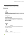
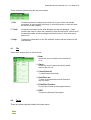
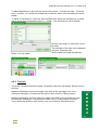
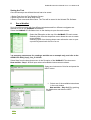
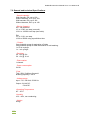
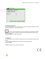
1
HelMed® Instruction Manual Vers. 3.0: 2008-12-05
AESKU.SYSTEMS
AESKU.SYSTEMS e.K.
Mikroforum Ring 3
55234
Wendelsheim, Germany
The Diagnostic Automation Company
Instruction Manual
IFA
1
HelMed® Instruction Manual Vers. 3.0: 2008-12-05
Table of Contents
1. Helmed® Installation
Helmed® Instrument Version 1.0
Introduction
Theory of operation
1.1
1.1.2
1.2
1.2.1
1.3
1.3.1
1.4
1.5
Installation Requirements
Accessories
Unpacking the Equipment
Placing the Helmed® in its designated area
Installing the Helmed®
Connectors on the instrument
Connecting the Helmed® / Warning Labels
Replacing the fuse on main power inlet
1-1
1-1
1-1
1-1
1-1
1-1
1-1
1-1
2. Helmed® Software
2.1
2.2
2.3
PC Requirements
Software Installation
Software structure
2-1
2-1
2-1
3. Accessories
3.1
IFA Module
3-1
4. Software Overview
4.1
Files
4.2
Tools
4.2.1 Slide Designer
4.2.2 Tools
4.2.3 Slide
4.2.4 Slide Info
4.2.5 Text Info
4.2.6 Well Info
4-1
4-1
4-1
4-1
4-1
4-1
4-1
4-1
4-1
5. Test Designer
5-1
5.1
5.2
2
Settings for Test Info
Settings for Steps
5-1
5-1
HelMed® Instruction Manual Vers. 3.0: 2008-12-05
6. Run a Worklist
6-1
7. General Specifications
7-1
8. Maintenance
8-1
8.1
8.2
Daily shut down procedure
Weekly shut down procedure
9. Calibration
9.1
3
Only trained personnel is allowed to calibrate the
carrousels and the peristaltic wash pump!
8-1
8-1
9-1
HelMed® Instruction Manual Vers. 3.0: 2008-12-05
Introduction
The Helmed IFA module is the software application for the Helmed system.
It provides programming options for the processing of IFA slides.
The system requires the addition of the supplied slide carrousel, the reagent rack and the
sample rack to accommodate IFA kit components.
To run the IFA module, a complete Helmed system is required. The Helmed System
consists of the following: the Helmed workstation, a computer (not provided), a monitor (not
provided), and a printer (not provided).
Up to ten Helmed workstations may be connected to a single computer.
The system automates the processing of IFA slides.
The Helmed IFA software contains AESKU IFA test files, but also allows the user to define
slides types and test files for other IFA Kits. Since the HelMed® is evaluated on AESKU IFA
Kits AESKU.Systems can not take responsibility for processing IFA kits of other
manufacturers.
A fluorescence microscope (not provided) is required in order to read the slides processed by
the Helmed workstation. Please follow the instruction of the IVD kit used.
Theory of Operation
The detection of antibodies is based on the principle of indirect immunofluorescence assay
(IIFA). Glass microscope slides are coated with tissue sections or cells (Hep-2-cells [ANA],
Granulocytes [ANCA] or Crithidia luciliae [nDNA]). If the patient’s serum contains specific
antibodies to these coated cells, then they will bind during the first incubation. Washing
steps will remove any unbound material. The bound antibodies are detected by Fluorescein
conjugated anti-human Immunoglobulins during a second incubation. A specific green
fluorescent staining of the antigen-antibody-complex can be visualized by the use of a
fluorescent microscope.
The Helmed IFA software automates the processing of IFA slides.
For in vitro Diagnostic use only.
In addition to the main software there are three additional software modules: well designer,
slide designer and test designer.
The well designer module is used to define the well on a slide (size [diameter],
type (shape [rectangle]).
The slide designer module is used to define the positions of the wells, along with the
surfaces, texts, and substrates affixed onto the slide to be processed.
The test designer module is used to define how a slide should be processed during a run.
Defined here are the dilution factors for screening or titration, the positions of controls and
samples on the slide, and the steps required for processing.
Test steps include: the volumes needed for transfer to the slide, incubation times, number of
wash cycles, volume of wash buffer(s), counterstain (optional), and mounting medium
dispensing (optional).
4
HelMed® Instruction Manual Vers. 3.0: 2008-12-05
1.1 Installation requirements
The requirements for the site where the equipment is to be installed are the following:
Do not place the equipment out of doors.
Do not place the equipment on a surface of flammable material.
Do not place the equipment so that it is difficult to access for maintenance or servicing.
Do not block air openings.
Do not place the equipment where it could get wet.
Do not position the equipment so that it is difficult to operate the mains disconnecting switch.
Do not let the equipment or its flexible cord come into contact with surfaces that are too hot
to touch.
Check that the nominal voltage shown on the equipment matches the supply voltage.
Check for a horizontal work surface.
Avoid to adjoin and to swinging the instrument during the operation.
1.1.2 Accessories
1 x HelMed ( Unit )
1 x Power Cord Schuko/German
1 x Fuse Power switch
1 x USB Cable
1 x Wash # 1
( Bottle with Tube )
1 x Wash # 2
( Bottle with Tube )
1 x Waste
( Bottle with Tube )
1 x Reagent Rack Standard
2 x Sample Racks (1-50 and 51-100)
1 x Calibration Tube
1 x Starter Kit; includes:
50 x 4 ml empty vials + caps
50 x 20 ml empty vials + caps
4 x Uncoated Nunc MTP
Also included:
Software CD with latest Software version, Instruction manual and Service manual.
Printed Version of the Instruction manual.
1.2 Unpacking the HelMed®
The HelMed® equipment normally ships in an industrial strength cardboard box set on a
pallet.
Remove the upper part of the cardboard box.
Remove all boxes of the accessories.
Place the instrument in its designated area.
Open the green cover and carefully remove the cardboard protections.
If there are any damages of the cardboard box and/or the instrument please contact your
local distributor.
5
HelMed® Instruction Manual Vers. 3.0: 2008-12-05
1.2.1 Placing the HelMed® in its designated area
Two people, one on each side of the instrument, are required to move it once it has been
unpacked. One hand holds the bottom front of the instrument. The other hand holds the
bottom back of the instrument. This method prevents any tendency for the instrument to tip.
It should be lifted equally by the two people, and set on the designated table.
1.3 Installing the HelMed®
First installation should be done by trained people only
according to the Service Manual!
1.3.1 Connectors on the instrument
1. Fluid lines
In the rear of the instrument you have the quick connectors for the wash solutions and for the
waste bottle. See bottle installation.
2. Main power inlet
The power inlet is located at the back of the instrument. The instrument power cord is
plugged into it.
3. USB Port
The instrument is connected to the PC via a USB cable. The USB port necessary for this
connection is located at the back of the instrument.
4. Bottle Installation
The bottles are labeled as follows:
WASH # 1 red
WASH # 2 blue
WASTE black
The tubing is correspondingly color-coded.
The quick connectors for the bottles are located at the back of the instrument.
5. USB Connection
Connect the instrument to the PC with the provided USB-cable.
6
HelMed® Instruction Manual Vers. 3.0: 2008-12-05
1.4 Connecting the HelMed® Equipment / Warning Labels
CONNECTING TO THE MAIN ELECTRICAL SUPPLY
The HelMed® equipment is connected via the socket on the back of the instrument, using the
supplied power cord.
Warning!
Electromagnetic compatibility and electrical safety tests have been performed using the
cord supplied by the manufacturer. However, if it is necessary to use another cord, be
sure that the new cord meets the following specifications:
Cable type: flexible cable with insulation and PVC cover with 3 conductors
(neutral, live and earth).
Cord length: 2m
Connector type: For IEC inlet. Connector for class I appliances.
Plug type: Plug type used in the country where the equipment is installed
and with grounded connection.
Connector, cable and plug must comply with the electrical safety requirements
applicable in your country.
It should be remembered that the equipment uses a switched power supply, which
automatically adapts to the main electrical supply voltage, and therefore does not
require any type of switching.
(Consult the specifications in order to check the operating margins).
CAUTION!
Using cables other than those specified may result in degraded electromagnetic
compatibility of the equipment.
DANGER!
To avoid the risk of electric shock, this equipment must be connected
to the main, grounded electrical supply.
7
HelMed® Instruction Manual Vers. 3.0: 2008-12-05
Warning labels on the instrument
Caution!
In case of a malfunction of the incubator, the labeled Microtiter Plate Holder may be
hot!
Caution!
Do not open the waste container peristaltic pump cover, while the pump is rotating.
The cylinders of the rotating pump may crush your fingers or cause other injury!
Caution!
The waste solution in the two liter waste bottle may contain infectious material.
Please follow your internal guidelines for biohazard/infectious waste disposal!
Caution!
According to WEEE 2002/96/EG for a proper disposal of the instrument you have to
follow local regulations or return the instrument to the manufacturer.
1.5 Replacing the fuse in the main cable inlet
DANGER!
8
HelMed® Instruction Manual Vers. 3.0: 2008-12-05
If you need to replace the fuse (T4A / 250V; 5x20mm) be sure that the power
supply cord is unplugged, before opening the fuse cover!
Do not plug in the power supply cord, when the cover for the fuse is open!
Plug in the power supply cord, only after first replacing the fuse and closing the
fuse cover!
THIS PRODUCT IS FOR IN VITRO DIAGNOSTIC USE ONLY.
Only trained staff, specially advised in methods of in vitro diagnostic testing, may
operate the instrument. Although this instrument is not considered toxic or dangerous
in conditions of normal use, refer to the following for maximum safety.
Recommendations and precautions.
We recommend avoiding contact with eyes and skin, and wearing disposable gloves,
when you are working with human specimens!
2 HelMed® Software
2.1 PC Requirements
Windows XP or Windows Vista.
Windows 2000 will also work. Older systems should comply with the specifications
below. Both 32bit and 64bit operating systems are fine.
At least 512 MB RAM.
At least a 20 GB hard drive.
Monitor must support a minimum resolution of 1280x1024.
2.2 Software Installation
Installing the HelMed® software.
Insert the HelMed® program installation CD into the computer disk drive. Run the
installation program with the file “HelmedIFASetup_xxx.exe” on the CD.
Accept the default options and follow the instructions as they are displayed.
A HelMed® Icon will be installed on the desktop.
Helmed IFA Software xxx
3. Accessories
3.1
IFA Module
Software
Helmed System IFA Software 1.0
9
HelMed® Instruction Manual Vers. 3.0: 2008-12-05
Hardware
Slide Carrousel
MTP Carrousel
Reagent Rack
Sample Racks
Bottles and Tubings
WASH # 1 red (including the tubing which is correspondingly color-coded).
WASH # 2 blue (including the tubing which is correspondingly color-coded).
WASTE black (including the tubing which is correspondingly color-coded).
4. Software Overview
IFA Software Main Screen
10
HelMed® Instruction Manual Vers. 3.0: 2008-12-05
There are three options along the top of the screen:
1. File
Contains options for creating a new work list, to open a work list already
processed, to close one/all work list(s), to print the preview, to save the work
list and to exit the program.
2. Tools
Contains the modules for the slide designer and the test designer. It also
contains the order to: prime the instrument, scan the rack layout, switch on/off
the barcode reader and the backlight, and the function to "scan rack layout
before run".
3. Help
Contains the information on the IFA software version and the contact for the
manufacturer.
4.1
File
There are 9 options given in the file menu:
1. New:
Allows the user to create a new work list for
a run.
2. Open:
Allows the user to open a previously saved
work list file of a run.
3. Close/Close all:
To close one/all work list(s).
4. Save/Save as:
To save a programmed work list file and to
give it a name.
5. Print/Print Preview:
To print the work list of the programmed run.
6. EXIT:
To leave the Helmed IFA program.
4.2
Tools
There are seven options listed in the tools menu:
11
HelMed® Instruction Manual Vers. 3.0: 2008-12-05
1. Slide designer:
Opens the Slide Designer screen. Contains
the Well Designer Module. Refer to section
4.2.1 for details of the Slide Designer
screen.
2. Test designer:
Opens the Test Designer screen. Refer to section 5 for details of the Test Designer creen.
3. Prime Instrument:
Primes the Instrument with Wash solution
Wash #1/ Wash #2 at the beginning of a
run or as a shut down procedure at
the end of a day.
4. Change Rack Layout:
Scans the positions of each rack.
5. Bar Code Reader:
To switch the Barcode reader on/off .
6. Scan Rack Layout before:
When this function is enabled, the rack
layout will be scanned before a run.
7. Enable Back Light:
When this function is enabled, the
Backlight will work in the different colors
(each color has a different meaning).
4.3
Help
There are two options listed in the Help menu:
User manual: Contains the User manual as a
pdf file.
About:
4.2.1 Slide Designer
12
Information about the software
version
HelMed® Instruction Manual Vers. 3.0: 2008-12-05
First, select the Tools option at the top of the Helmed IFA main screen.
Second, select Slide designer, from the drop down menu, to open the Slide Designer
screen.
The slide must be designed before creating a new test design. The Helmed IFA software is
pre-programmed for AESKU IFA slides, but is open to allow the user to define slides types
from any manufacturer.
There are two options along the top of the screen:
1. Slide:
Contains options for creating a new slide or to
open an existing slide.
2. Tools:
Contains the module of the well designer for
creating a new well or to open an existing well.
4.2.2 Tools
There are five options listed in the well designer menu:
1.
New:
2.
Open:
To create a new well type.
To open an existing well type.
3.
Save:
4.
Save as:
5.
Close:
To quick save a programmed well.
To save a programmed well as a named well.
To close the well designer and come back to
the slide designer.
Create a new well by filling in the information about type and size (X- & Y- Size) of a well.
13
HelMed® Instruction Manual Vers. 3.0: 2008-12-05
Measure the size of a circular or rectangular well:
For circular wells, measure the diameter across the center of the well. For rectangular wells,
measure the width and the height of the wells. All measurements are in millimetres.
Multiply the result by 10 and enter the value into the X-Coord- and the Y-Coord- field (XCoord & Y-Coord must be the same with a circular well).
It is possible to set multiple dispensing points in this module (recommended for slides with
large wells).
14
HelMed® Instruction Manual Vers. 3.0: 2008-12-05
4.2.3 Slide
The Slide Designer is used to modify an existing slide layout or to define new slides for
additional assays that will be run using the Helmed IFA Module
NOTE: AESKU slides are pre-programmed and should not be edited.
The Slide Designer has the flexibility to program most IFA slides.
It is the responsibility of the user to make proper adjustments, if needed, and to verify
the slide designer settings prior to use.
This section will describe how to design a new slide.
NOTE: The Slide Designer Main Screen will open a default slide file. This slide has to be
changed.
There are three Info fields listed in the Slide Designer:
1. Slide Info:
Contains options to
select the
manufacturer, color,
thickness and width
of a slide.
2. Text Info:
The Text option can
be used to place text
on a slide.
3. Well Info:
Contains the options
to define the number
of wells and their
positions on the
slide. Select the
well (created in the
well designer),
color (optional),
function (optional)
and the substrate.
4.2.4 Slide Info
Select a manufacturer by using the drop down menu in the Manufacturer line.
15
HelMed® Instruction Manual Vers. 3.0: 2008-12-05
To add a Manufacturer, right click the mouse on the arrow. A window will open. Press the
plus (+)- button. You will get an Untitled line in which the name of the manufacturer can be
added.
To delete a manufacturer, follow the same procedure but select the manufacturer to delete
with a mouse click and press the minus (-) - button. The manufacturer will be deleted.
Use the Color button to select the color of
the slide.
The thickness of the slide can be adjusted
using the Thickness field.
Set the width of the slide by selecting
25mm or 26 mm option.
4.2.5 Text Info
The X and Y positions define the upper, left position where the text begins. Enter the text in
the field.
Measure the distance from the left edge of the slide to the right edge of the text in
millimetres. Multiply by 10 and enter the value in the X-Coord (1/10mm) position.
Measure the distance from the upper front edge of the slide to the top edge of the text
in millimetres. Multiply by 10 and enter the value in the Y-Coord position (1/10mm).
Texts can be placed left to right, bottom to top, top to bottom (Orientation field).
16
HelMed® Instruction Manual Vers. 3.0: 2008-12-05
4.2.6 Well Info
Numbers of wells are defined by pushing the plus (+)- button in the Well Info field. Complete
the “Caption” - column by numbering the wells continuously.
Wells can also be removed by the minus (-)- button.
Well positions are defined by measuring from the designated front and left edges of the slide
to the center of the well. A ruler, for X and Y positioning, is shown on
the screen. The 0 / 0 axis is in the upper, left corner.
Measure the X position of the first well, in millimetres, using a metric
ruler. The X position is the distance from the left edge of the slide to
the center of the well. Multiply the distance measured by 10. Enter the
value into the X-COORD (1/10 mm) field.
Measure the Y position of the first well, in millimetres, using a metric
ruler. The Y position is the distance from the upper front edge of the
slide to the center of the well. Multiply the distance measured by 10.
Enter the value into the Y-COORD (1/10 mm) field.
Repeat these steps for all other wells on the slide.
17
HelMed® Instruction Manual Vers. 3.0: 2008-12-05
Select a Well using the drop down menu in the Well column. The Well has
been defined and previously saved in the Well Designer. Refer to section 4.2.2
for further information.
Using the color column, the well can be colored.
To define a function for a well position (i.e. the position of a calibrator), select
the drop down menu of the function column.
Select a Substrate by using the drop down menu in the Substrate column.
Substrates can be added by a right mouse click on the arrow. A window will
open. Press the plus (+)- button to get an Untitled line in which the name of
an additional Substrate can be added.
Saving the slide design
Once the slide is defined with all information needed, it has to be saved.
1. Select Slide from the Slide Designer Screen
2. Select Save as from the drop down menu
3. Enter a slide name and select Save. The slide will be saved in the Helmed IFA
Software.
5. Test Designer
The Test Designer is used to create a new test or to change settings of an existing test if
required. Refer to section 4.2.1 for details on creating a new slide.
18
HelMed® Instruction Manual Vers. 3.0: 2008-12-05
NOTE: AESKU tests are pre-programmed and should not be edited.
The Test designer has the flexibility to program most IFA assays. The parameters of these
assays should be based on the instruction manual contained within the kit.
It is the responsibility of the user to make proper adjustments and then validate the
test before use.
Select the Tools option at the top of the Helmed IFA Main
Screen.
Select Test designer from the drop down
menu to open the Test Designer screen.
Select the Test option at the top of the Test Designer Main
Screen.
Select New from the drop down menu to create a new test.
There are two Info fields listed in the Test Designer:
5.1
Test Info.
5.2
Steps.
5.1 Settings for Test Info:
Select the Manufacturer, the Substrate, the Well, the Slide and Wash type that should be
used in the test by using the drop down menu on every line.
The function Allow Well Pooling is for using different conjugates on one slide.
For IFA assays requiring incubation(s) higher than room temperature (23C-25C), the Test
Run Temperature can be adjusted. However, the specialized carrousel with the
heating specification must be used.
The standard carrousel will not work.
NOTE: The Test Designer Main Screen will open
with default settings Test Info. These settings have
to be changed before starting with the Step
selection.
Select a Manufacturer by using the drop down
menu in the Manufacturer line. A Manufacturer’s
name can be added by a right mouse click on the arrow. A window will open. Press the plus
(+)- button to get an Untitled line in which the name of an additional manufacturer can be
added.
If a Manufacturer should be deleted, then select the manufacturer to delete with a mouse
click and press the minus (-)- button. The manufacturer will be deleted.
Select a Substrate by using the drop down menu in the Substrate line. Substrates are
defined in the Slide Designer. For further information refer to Selection 4.2.6.
Select a Well by using the drop down menu in the Well line. Wells are defined in the Well
Designer (Slide Designer – Tools). For further information refer to Selection 4.2.2.
19
HelMed® Instruction Manual Vers. 3.0: 2008-12-05
Select a Slide by using the drop down menu in the Slide line. Slides are defined in the Slide
Designer. For further information refer to Selection 4.2.1.
Select a Wash type by using the drop down menu in the Wash type line. Wash types can be
added by a right mouse click on the arrow. A window will open. Press the plus (+)- button to
get an Untitled line in which the name of an additional wash buffer can be added.
If a wash buffer should be deleted, then select the one to delete with a mouse click, and
press the minus (-)- button. The wash buffer will be deleted.
Selecting Allow Well Pooling uses different conjugates on one well.
Run Test Temperature can be increased for a special test (a special heater carrousel is
needed – available on request).
5.2 Settings for Steps:
Select from the list, on the right side, the steps that should
be processed in a test. There are seven options listed: Dilution,
Incubation, Wash, Conjugate Addition, Counterstain Addition,
Mounting Medium Addition and Composite.
The steps to process slides must be defined. Selecting Test Steps from the right side of the
screen, following the instruction manual of the manufacturer.
NOTE: All step files will open with default settings. These settings have to be changed
before adding to the Step.
AESKU test steps are pre-programmed and should not be edited.
The following instructions for creating test steps are an example only, and refer to the
AESKU IFA Kit instruction manual.
1. Select Dilution from the right side of the screen (double-click or add–button). A window
will open in order to define samples, controls, diluent and dispensing (transfer to the slide).
1.1 Define the Screening dilutions for the
Samples. This dilution will be used for
all patient samples. Define the Titration
dilutions of interest for the samples as
well. The titration dilutions are added by
clicking the ADD button.
20
HelMed® Instruction Manual Vers. 3.0: 2008-12-05
1.2 Define the Controls. Add the Controls
needed with the plus (+) - button. Select
the position (default setting undefined =
starts always at the first position of a slide).
Edit the names of the controls.
Select a dilution if needed (default setting
1/1 for ready-to-use controls).
Select between controls dispensed before
first patient or controls dispensed on every
slide.
1.3 Select the Diluent by using the drop down
menu of the dilution medium line. Select between
Wash Solution and Diluent. If Wash Solution is
selected, then the Wash Buffer of the test will be
used. If Diluent is selected, then the Diluent line
will be enabled and the test Diluent will be used.
A Diluent can be selected by using the drop down
menu in this line. Diluent types can be added by a
right mouse click on the arrow. A window will
open. Press the plus (+) - button to get an
Untitled line in which the name of an
additional Diluent can be added, as well as its
Manufacturer.
.
1.4 Define the Dispensing settings for the
transfer to the slide. These settings are divided
by Dispensing Volume, Dispensing Height and
Dispensing Speed.
The volume needed to cover the entire well
depends on the well size (i.e. Round 50x50 =
30µl; Round 80x80 = 80µl).
The Dispensing Height is the dispensing needle
height above the slide when dispensing fluid. The
Dispensing Speed is arbitrary and relates to the
revolutions per minute of the volumetric pump
during dispensing.
These Parameters must be verified and
validated for the slides.
After these settings are entered press OK. The first test step appears under
Step on the left side of the screen.
21
HelMed® Instruction Manual Vers. 3.0: 2008-12-05
2. Select Incubation from the right side
of the screen (double-click or add–
button) and define the incubation time
needed for the first incubation. Then
click OK.
Incubation step appears under Step on the left side of the screen.
3. Select Wash from the right side of
the screen (double-click or add–button).
Enter the number of required wash
cycles.
Volume, Dispensing Height, Dispensing
Speed and Aspiration Height settings
have to be verified and validated.
The volume needed to cover the entire well depends on the size of the well.
The Dispensing Height is the height of the dispensing needle above the slide when
dispensing fluid.
The Dispensing Speed is arbitrary and relates to the revolutions per minute of the volumetric
pump during dispensing.
The Aspiration Height is the height of the aspiration needle when aspirating the fluid from the
slide.
If the option Enforce Timing is selected, then the
Incubation Time of the step prior to washing will be strictly
adhered too.
After these settings are entered press OK. The washing step appears under
Step on the left side of the screen.
If Enforce Timing was selected for the incubation time, then the Wash Step
appears in red font.
22
HelMed® Instruction Manual Vers. 3.0: 2008-12-05
4. Select Conjugate Addition from the
right side of the screen (double-click or
add–button). Select a conjugate using
the drop down menu in Conjugate line.
Conjugates can be added by a right
mouse click on the arrow. A window
will open. Press the plus (+) - button to
get an Untitled line in which the name of
an additional Conjugate can be added,
as well as its Manufacturer. Define the
settings for the Conjugate Addition,
Dispense Height, Dispense Speed and
Aspirate Height. These settings must
be verified and validated.
If it is necessary to first wash the wells with Conjugate, then the
number of cycles must be defined. Up to three cycles are possible.
For every cycle, edit the Volume needed to cover the entire well.
If there is no need for more than one cycle of Conjugate addition,
then only fill in the µl’s needed for Volume #1. After these settings
are entered press OK.
The Conjugate Addition step appears under Step on the left side of the
screen.
Step 3 and Step 4 can be combined in a Composite Step. The function of this step is to
immediately add conjugate to each well after it is washed.
Select Composite from the right side of the screen. Composite
appears under Steps on the left of the screen when this step is
enabled. On the right side of the screen there are now three
different steps available: Wash, Conjugate Addition and
Counterstain Addition.
Select Wash and follow the instructions in 3 above.
The Wash appears under Composite on the left side of the screen.
Then select Conjugate Addition and follow the instructions in 4 above.
The Conjugate Addition appears under Composite on the left side of
the screen. To continue defining Steps click once on Step on the left
side of the screen.
To continue defining steps click once on Step on the left side of the screen
23
HelMed® Instruction Manual Vers. 3.0: 2008-12-05
5. Select Incubation from the right side of the screen (double-click or add–button) and define
the Incubation time needed for the Conjugate incubation.
Then click OK.
Incubation step appears under Step on the left side of the screen.
6. Select Wash from the right side of the screen (double-click or add–button). Define how
many cycles a well is required to be washed.
Settings such as Volume, Dispensing Height, Dispensing Speed, Aspiration Height
have to be verified and validated.
The volume needed to cover the entire well depends on the size of the well.
The Dispensing Height is the height of the dispensing needle above the slide when
dispensing fluid.
The Dispensing Speed is arbitrary and relates to the revolutions per minute of the volumetric
pump during dispensing.
The Aspiration Height is the height of the aspiration needle above the slide when aspirating
the fluid.
If the option Enforce Timing is selected, then the Incubation time of the step before the
washing will be strictly adhered too.
After these settings are entered, press OK. The Washing Step appears
under Step on the left side of the screen.
If Enforce Timing has been selected, the incubation time will be strictly
adhered to and the Wash Step appears in red fonts.
7. As an optional step for IFA, you may select Counterstain Addition from the right side of
the screen (double-click or add–button).
Define the Volume needed to cover the entire well.
The dispensing height is the height of the dispensing needle above the slide when
dispensing fluid.
The dispensing Speed is arbitrary and relates to the revolutions per minute of the volumetric
pump during dispensing.
The Aspiration height is the height of the aspiration needle above the slide when aspirating
the fluid.
Settings, such as Volume, Dispensing Height, Dispensing Speed, and Aspiration
Height must be verified and validated.
Step 6 and Step 7 can be combined in a Composite Step. The function of this step is to
immediately add counterstain to each well after it is washed.
Select Composite from the right side of the screen.
Composite appears under Steps on the left of the screen
when this step is enabled. On the right side of the screen,
there are now three different steps available: Wash,
Conjugate Addition and Counterstain Addition. Select
Wash and follow the instructions in 3 / 6.
24
HelMed® Instruction Manual Vers. 3.0: 2008-12-05
The Wash appears under Composite on the left side of the screen.
Then select Counterstain Addition follow the instructions in 7.
The Counterstain Addition appears under Composite on the left side
of the screen.
To continue defining Steps click once on Step on the left side of the
screen.
8. Select Incubation from the right side of the screen (double-click or add–button) and define
the incubation time needed for the counterstain incubation.
Then click OK. Incubation step appears under Step on the left side of the screen.
9. Select Wash from the right side of the screen (double-click or add–button). Define how
many wash cycles are required.
Settings as Volume, Dispensing Height, Dispensing Speed, Aspiration Height have to
be verified and validated.
The volume needed to cover the entire well depends on the size of the well.
The dispensing height is the height of the dispensing needle above the slide when
dispensing fluid.
The dispensing Speed is arbitrary and relates to the revolutions per minute of the volumetric
pump during dispensing.
The Aspiration height is the height of the aspiration needle above the slide when aspirating
the fluid.
It is recommended to select Enforce Timing for the Counterstain
Incubation. By doing so, the incubation time will be strictly adhered
too.
Then click OK. Wash step appears under Step on the left side of the
screen.
10. Select Mounting Medium Addition from the right
side of the screen (double-click or add–button).
Define the settings of the Mounting Medium Addition
Volume, Dispense Height, Dispense Speed, and Aspirate
Height. These settings have to be verified and
validated. After these settings are programmed press
OK.
The Mounting Medium Addition step appears under Step on the left
side of the screen.
Selecting Counterstain Addition as an
optional step for IFA in an Composite step
see the ranking of the steps in the following
image:
25
HelMed® Instruction Manual Vers. 3.0: 2008-12-05
Saving the Test
Once all test steps are defined the test has to be saved.
1.Select Test from the Test Designer Screen
2.Select Save from the drop down menu
3.Enter a Test name and select Save. The Test will be saved in the Helmed IFA Software.
6.
Run a Worklist
Up to four different tests with four different substrates and four different conjugates are
allowed to run on one HelMed® Workstation.
Select the HelMed® IFA Software icon on the desktop to open the main screen.
Select the File option at the top of the HelMed® IFA main screen.
Selecting New from the drop down menu allows the user to create
a new worklist.
Selecting Open from the drop down menu allows the user to open
a previously saved work list file of a run.
The following instructions for creating a worklist are an example only, and refer to the
AESKU IFA ANA_Hep2_12w_51.100 Kit.
Select New from the drop down menu in the file option of the HelMed® IFA main screen.
New worklist - Step 1 of 5 will open where all available instruments are shown.
Select one instrument of this list and press the
NEXT button.
1. Select one of the available tests shown
in the next window
New worklist – Step 2 of 5 by pushing
the Add button and then the NEXT
button
26
HelMed® Instruction Manual Vers. 3.0: 2008-12-05
2. New Worklist – Step 3 of 5 shows the selected test
Selected test is stated. The slide
that belongs to the selected test is
shown in the drop down Use the
drop down menu in the MODE line
to select between doing screening
or titration of the samples.
Enable the “Add another test”
button let the user come back to
New worklist – Step 2 of 5 to add
additional tests.
Press NEXT.
3. Using Barcode labeld samples the barcode reader has to be enable before creating a
new worklist!
Select Tools from the HelMed® IFA main screen.
Enable the Barcode reader in the drop down menu.
The barcodes of the samples and the racks as well
will be scanned in New Worklist – Step 4 of 5.
Standard sample tubes are: 5 ml tube
Ø13 x 75mm
4. New worklist – Step 5 of 5
Gives the information about the
instrument, selected test(s) for the
worklist that will be configured.
Press FINISH to come to the layout
screen.
The worklist layout will open as a default setting with an Info field on the right
27
HelMed® Instruction Manual Vers. 3.0: 2008-12-05
side of the screen containing Test Info, Wash Solution Info, Reagent Rack Info, Slide Info.
There are four options listed on the top of the worklist screen:
Layout
28
HelMed® Instruction Manual Vers. 3.0: 2008-12-05
The Layout screen gives the information about where to put the reagents, controls,
samples and slides.
After all samples are filled in and selected (refer to 2. Sample Data) by ticking the layout
default screen become the real layout screen where the amount of slides needed will be
shown.
Sample Data
Sample Data has to be defined. Select the plus (+) - button to add samples when not
using the barcode reader. Fill in the Sample ID. Click all samples and dilutions that
should be processed in the run.
MTP
MTP shows how many strips are needed for the pre-dilution steps.
Status
Status gives the information about the action.
Starting the Worklist to run a program.
29
HelMed® Instruction Manual Vers. 3.0: 2008-12-05
After all slides, reagents, controls and samples are loaded, return to the Status option on the
top of the Worklist screen and press START.
While running the software
depicts two clocks. The large
clock shows the remaining
time of the whole run, while
the small clock shows the
remaining time of the actual
action currently taking place.
If needed, it is possible to
pause the run using the
PAUSE button.
As the system is then
unlocked, e.g. the samples
may be removed. Press
CONTINUE and the run will
go on.
If there is any reagent missing
(buffers, controls, conjugates)
the instrument will give an
alarm beep as well as a red
alarm light. The system is
unlocked during this time and
the run is stopped. The
carrousel will turn to the
position where the reagent is
missing. After refilling the
reagent bottle, the cover has
to be closed. Press OK to go
on with the run. The ERROR
report is shown in the status
option.
30
HelMed® Instruction Manual Vers. 3.0: 2008-12-05
7.0 General and technical Specifications
- Sample capacity:
With barcode, IFA: up to 100.
Without barcode, IFA: up to 150.
With barcode, EIA: up to 120.
Without barcode, EIA: up to 192.
- Dilution Capacity:
IFA: 192 positions.
1/1 to 1/160: one step (one well).
1/161 to 1/25600: two step (two wells).
EIA:
1/1 to 1/101: one step.
1/102 to 25000 using a predilution tube
- Pumps:
One peristaltic pump for aspiration of fluids.
One peristaltic pump for slide well and MTP well washing.
1 x 50 uL syringe.
1 x 1 mL syringe.
- Precision:
CV <3% @ 5uL.
CV <1% @ 10 uL
- Plate washer:
1 channel.
- Power consumption:
210 W
-Fuse
T4A / 250V; 5x20mm Ceramic!
breaking capacity 1.500 V
- Voltage range
Input: 115 / 240 Volt, 50-60 Hz.
Output: 24 Volt DC.
5 Volt DC.
-Operating Temperature
20° - 35°C
-Humidity
10% - 90%, non conducting
- Weight:
28 Kg.
31
HelMed® Instruction Manual Vers. 3.0: 2008-12-05
8.0 Maintenance
The daily maintenance is important for the proper operation of the instrument.
The following procedure is recommended.
We recommend to calibrate the carrousels during the yearly maintenance.
Only trained lab personnel is it allowed to calibrate the instrument!
To calibrate the peristaltic wash pump please look at section 3.3 of the Service Manual
8.1 Daily Shutdown
After a finished worklist the instrument has to be primed with distilled water.
This keeps the fluid lines in good condition and avoid particles in the needle and the tubings.
Replace wash solution with distilled water
Empty the wash bottle #1 and fill it with distilled water or disconnect the quick connector on
the bottle top and use a new bottle with distilled water.
Prime the instrument
1. Select Tools from the IFA Main Screen. Then select Prime Instrument:
2. Select your instrument
32
HelMed® Instruction Manual Vers. 3.0: 2008-12-05
3. Number of cycles:
8.2 Weekly maintenance
Prime the instrument once a week with 0,3 % Sodium Hydrochlorite (NaOCl) solution.
Follow the steps from 8.1 to prime instrument.
Attention: After cleaning the instrument with Sodium Hydrochlorite (NaOCl)
solution it is necessary to prime the instrument with distilled water three times with
nine cycles each!
Follow procedure 8.1 to prime instrument.
9. Calibration
Only trained personnel is allowed to calibrate the carrousels and the peristaltic wash
pump!
For calibrating the wash pump you need the special calibration tube
Part No. M094#4
Detailed procedures are in the Service Manual.
33