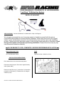
1
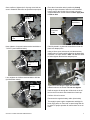
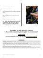
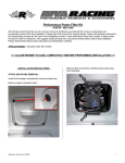
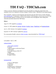
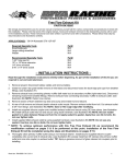
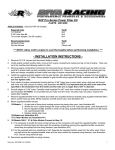
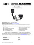
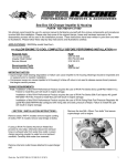
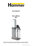
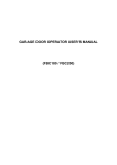
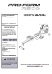
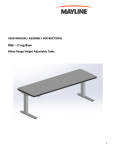
“Last Drop” Oil Extraction System PART# - RY10030-OES APPLICATION(S): Yamaha VX Models & V1 Models with 110hp 1100 Engines. We strongly recommend the use of a service manual to familiarize yourself with the various components and procedures involved with this installation. Please note that some of the original clamps, hoses and hardware removed in the disassembly process will be used in the installation process. These instructions have been written in step-by-step format and refer to illustrations. Read through instructions entirely before performing installation. Please follow these step-by-step instructions and illustrations carefully. ALLOW ENGINE TO COOL COMPLETELY BEFORE PERFORMING INSTALLATION Required Specialty Tools Part# Oil / Fluid Extraction Pump 18-2720 for 6 liter / OIL03 for 15 liter - INSTALLATION INSTRUCTIONS Place watercraft in a level and horizontal position. Disconnect safety lanyard. Disconnect negative battery cable. (black cable) Remove oil tank filler cap.(1) Insert tube of oil extraction pump(2) in oil filler hole (3). Extract all the oil using the extraction pump. Word doc. Part #RY10030-OES © MS 9/29/2014 1 Note: To ensure as much oil as possible is removed, place oil extraction tube in hole located in the bottom center of the oil tank. (see illustration below) Place Oil Extraction Tube Here Inspect drain plug bolt for crush washer. If crush washer is missing from bolt, it may still be attached to the oil pump. Use an inspection mirror & insure the crush washer has been removed. It should appear as the illustration below. If crush washer is stuck to oil pump, use a small flat blade screwdriver to loosen from oil pump. Drain Bolt Area – no crush washer Remove plastic driveline coupler cover. Locate the oil pump drain bolt on the back of the engine. Oil Pump Drain Bolt Note: RIVA Racing suggests replacing the oil filter at this time. In order to correctly install the support bracket, it is required to loosen the oil pump cover. This may cause the o-ring seal to be disturbed, resulting in an oil leak. RIVA Racing suggests replacing the oil pump cover oring with the new o-ring supplied with this kit. The oil pump drain bolt size can be either a 12mm or 13mm head, depending upon the model year. Use an inspection mirror to ensure you are removing the oil pump drain bolt. There are 2 bolts in this area. The drain bolt is located slightly higher than the other bolt, and to the left. (port side) Note: When oil pump drain bolt is removed, 1/2 to as much as 1 full quart of oil can still drain from the engine. Tip: Before removing the drain bolt, place a container (like a small aluminum foil baking tray) under the oil pump area to catch the excess oil. Remove the 3, M6 (1) bolts from the oil pump cover. Next, remove the two M8 socket head bolts (2) from the oil pump cover. Carefully remove the oil pump cover. 1 2 Remove oil pump drain bolt. Allow all the oil to drain from the motor. (this may take a few minutes) Use oil extraction pump to remove oil from container that was placed under the oil pump. Remove & properly discard container. Word doc. Part #RY10030-OES © MS 9/29/2014 2 Remove the o-ring from the oil pump. Clean the o-ring sealing area of the oil pump cover plate & oil pump to ensure a proper seal. Make sure no debris or foreign material enters the internals of the oil pump. Replace old o-ring with the supplied new o-ring. Hex Adaptor Using a 13mm socket, tighten the black hex adaptor piece to 5 foot pounds. (60 inch pounds) DO NOT OVERTIGHTEN THE HEX ADAPTOR! Over tightening the hex piece may result in the threads breaking off in the oil pump. Tip: Apply grease to the new o-ring before installation. This will assist with holding the o-ring in place when reinstalling the oil pump cover. Reinstall oil pump cover with only the 2 M8 socket head bolts, and the one M6 bolt as shown in the illustration below. Note: Apply blue Loctite to bolts. Install the supplied support bracket by sliding the grommet over the hex adaptor piece. Use window cleaner on the grommet so it slides into place easily. Note: The support bracket only fits in one position. Make sure the raised spacers are facing towards the oil pump cover. Loosely secure the support bracket in place using the 2 supplied M6 x 85mm socket head bolts. Note: Apply blue Loctite to bolts. Make sure the support bracket is installed “naturally” so there is no pressure in any direction on the black hex adaptor. M6 x 85mm socket head bolts Support Bracket Do not fully tighten bolts yet. Keep cover plate slightly loose. Make sure the new o-ring is secure in the o-ring groove & does not get pinched or damaged. Slide the supplied crush washer over the threaded end of the black hex adaptor & install where the oil pump drain bolt was located. Tip: Place a very small amount of grease between the hex adaptor & the crush washer. This will hold the crush washer in place while installing the black hex adaptor. Word doc. Part #RY10030-OES © MS 9/29/2014 Black Hex Adaptor 3 Once confirmed, tighten the 3 oil pump cover bolts as seen in illustration below first to specified torque specs. Place the oil extraction tube in position by loosely bolting the upper bracket of the tube to the threaded boss mount on the left side of the oil tank, using the supplied M8x16mm socket head bolt. Note: apply blue Loctite to bolt. Tighten to 11ft.lbs Threaded Boss Mount Oil Extraction Tube Tighten to 7.2 ft.lbs. Next, tighten to 2 support bracket socket head bolts to 7.2 ft.lbs. (see illustration below) Carefully thread in by hand the brass flare nut into the black hex adaptor piece. Using a 13mm open end wrench, hold the black hex adaptor piece in position while tightening the brass flare nut with a 7/16” open wrench. Note: You DO NOT want to further tighten the black hex adaptor piece. Torque to 7.2 ft.lbs. Last, retighten the 2 M8 socket head bolts to 20ft.lbs. (see illustration below) Torque to 20 ft.lbs. Tighten the bolt holding the upper bracket on the extraction tube to the oil tank. Do not over tighten. Refill the engine oil through the oil filler hole on the oil tank to the correct level and reinstall the oil tank cap. Confirm oil level is correct. Reconnect the negative battery cable. (black cable) Thoroughly inspect engine compartment and bilge for tools, rags, parts, etc. Run craft on stand using flush kit to check for proper operation & confirm there are no oil leaks. Word doc. Part #RY10030-OES © MS 9/29/2014 4 Reinstall plastic driveline coupler cover. Installation is now complete. You are now ready to use your “Last Drop” Oil Extraction System. Note: Removing the oil from the engine is a two step process. First, remove all the oil from the oil tank. Second, remove the cap on top of the oil extraction tube. Attach the supplied adaptor hose to the top of the oil extraction tube. Attach the hose from your fluid extractor to the adaptor hose. After extracting the engine oil from the oil pump area, remove the adaptor hose & reinstall cap on top of oil extraction tube. Remember, the water belongs to everyone. Please ride responsibly and respect the environment! Technical Support For answers to questions regarding installation or trouble shooting RIVA Performance Products contact: RIVA Technical Support directly at (954) 247-0705 or by e-mail at [email protected]. Limited Warranty RIVA Oil Extraction Systems carry a 6 Month limited warranty to the original purchaser. They are warranted to be free of defects in materials and workmanship under normal use and service. Customer modified components will be void of warranty. This warranty is limited to defects in the primary components only. Finish and/or wear marks in or on primary components are not covered under this warranty. RIVA Racing’s liability is expressly limited to the repair or replacement of the components contained within or associated with this kit. RIVA Racing agrees to repair or at RIVA’s option, replace any defective unit without charge, if product is returned to RIVA Racing freight prepaid within the warranty period. Any equipment returned which, in RIVA’s opinion, has been subjected to misuse, abuse, overheating or accident shall not be covered by this warranty. RIVA Racing shall have no liability for special, incidental or consequential damages or injury to persons or property from any cause arising from the sale, installation or use of this product. No other warranty, express or implied, including, but not limited to the implied warranties of merchantability and fitness for a particular purpose, applies. Various states do not allow for the limitation of incidental or consequential damages and therefore the above exclusion or limitation may not apply to you. Warranty does not include the expenses related to freight or transportation of parts or compensation for any inconvenience or loss of use while being repaired. A copy of the original invoice and a Return Authorization Number (RA#) must accompany all warranty claims. Warranted replacement parts will be returned freight collect. Word doc. Part #RY10030-OES © MS 9/29/2014 5