1
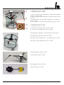
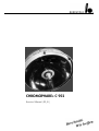
CHROMOPHARE® C 952
Service-Manual (D, E)
Inhaltsverzeichnis
für Service-Manual
C 952
Themen
Einführung
4
Technische Daten
5
Schaltungsbeschreibung
2
Seite
7 - 13
Ersatzteilliste
14 - 16
Bildliche Ersatzteildarstellung
17 - 29
Meßpunkte
30
Einstellpunkte
31
Einstellpunkte in Verbindung mit dem Diagnosestecker
32
Einstellen des Gewichtsausgleichs
33 - 34
Einstellung der Federkennlinie
34 - 35
Anschlußplan
Transformatoren am Deckenrohr der Leuchte
36
Anschlußplan Transformatoren und
Notstromumschaltrelais am Deckenrohr der Leuchte
37
Anschlußplan
Transformatoren separat im bauseitigem Wandschaltkasten
38
Anschlußplan Transformatoren und Notstromumschaltrelais
separat im bauseitigem Wandschaltkasten
39
Sicherungen
40
CHROMOPHARE® C 952 Service Manual (D, E)
Table of contents
for Service-Manual
C 952
Contens
Page
Introduction
4
Technical Data
6
Functional Description
7 - 13
Spare Part List
14 - 16
Graphic spare part description
17 - 29
Measuring Points
30
Adjustment Points
31
Adjustment by use of diagnostic plug
32
Adjusting the Weight Counter Balance
33 - 34
Adjustment of the Spring Characteristic
34 - 35
Electrical Diagram
Transformers mounted on the ceiling tube
36
Electrical Diagram
Transformers and emergency relays mounted on the ceiling tube
37
Electrical Diagram
Transformers mounted in a wall box on side of building
38
Electrical Diagram Transformers and emergency relais mounted in a
wall box on side of building
39
Fuses
40
CHROMOPHARE® C 952 Service Manual (D, E)
3
Einführung
Introduction
CHROMOPHARE® C 952 Brillant
CHROMOPHARE® C 952 Brilliant
Noch mehr Licht im OP-Feld
Brighter light at the surgical site
• Mit neuentwickelter Reflektrotechnik ein
Maximum an Lichtausbeute
• Maximum light efficiency with improved
reflector technology
• Einzigartige Brillantoberfläche der Reflektorsegmente
• Unique brilliant surface of reflector segments
• Mehr Licht, weniger Streuung durch die
klare Lichtaustrittsfläche
• Increased intensity via clear light emission
surface
• Keine zusätzliche Wärmebelastung
• ThermoSorb® filter keeps it cool
• Unveränderte, bewährte
CHROMOPHARE® Beleuchtungstechnologie
• Proven CHROMOPHARE® lighting technology
• Entspanntes, augenschonendes Arbeiten
im OP-Feld
4
CHROMOPHARE® C 952 Service Manual (D, E)
®
Technische Daten Berchtold CHROMOPHARE Operationsleuchte C 952
Elektrische Anschlußdaten Trafo
Gleichspannung
Wechselspannung
Beleuchtungsstärke in 1 m Abstand
bei Farbtemperatur 4.500 K
bei Farbtemperatur 3.600 K
Durchmesser des Polygon-Reflektors
Durchmesser des Leuchtengehäuses
Licht-Austrittsfläche
Durchmesser kleines Lichtfeld
Durchmesser großes Lichtfeld
Lichtfeld-Verstellung
Gleichbleibender Lichtfeld-Durchmesser ohne Nachfokussierung konstant bis
Hauptlichtquelle 1 Halogenlampe
Reservelichtquelle 1 Halogenlampe
Automatische Umschaltung auf Reservelicht bei Defekt der Hauptlichtquelle
Mittlere Lebensdauer der Halogenlampe
Aktionsradius der Fahrbahn
Höhenverstellung des Leuchtenkörpers
Elektrik entsprechend den Sicherheitsstandards-Standards nach VDE und IEC
110/115/120/220/230/240 Volt, 450 VA
24,4 V - 30,0 V/max. 16 A
23 V - 30 V ~
150.000 Lux
200.000 Lux
870 mm
950 mm
90 % der Leuchten-Unterseite
200 mm
350 mm
stufenlos mit Servomotor
800 mm Höhen-Differenz
250 Watt / 22,8 V, Artikel Nr. CZ 907-22
250 Watt / 22,8 V, Artikel Nr. CZ 907-22
mit optischer Anzeige
ca. 1000 Brennstunden
1950 mm
1150 mm
CHROMOPHARE® C 952 Service Manual (D, E)
5
Berchtold CHROMOPHARE® Surgical Lights C 952
Power requirements Transformer
Direct voltage
Alternating voltage
Illuminance measured at 1 m distance:
with colour temperature 4.500 K
with colour temperature 3.600 K
Diameter of polygon reflectors
Diameter of lamp housing
Light emission surface
Diameter of small light field
Diameter of large light field
Light field adjustment
Constant light field diameter without focussing
Main light source
Reserve light source
Automatic switching of reserve lamp
Average service life of halogen lamp
Swivel radius of lamp housing
Height adjustment of lamp housing
Electrical system in accordance with VDE and IEC standards
6
110/115/120/220/230/240 V, 450 VA
24,4 V - 30,0 V/max. 16 A
23 V - 30 V ~
150.000 Lux
200.000 Lux
870 mm
950 mm
90 % of light underside
200 mm
350 mm
infinitely variable with servomotor
constant up to 800 mm difference in height
250 Watt / 22,8 V, article no. CZ 907-22
250 Watt / 22,8 V, article no. CZ 907-22
with visual indication
approx. 1000 hours
1950 mm
1150 mm
CHROMOPHARE® C 952 Service Manual (D, E)
Schaltungsbeschreibung der
Berchtold
CHROMOPHARE®
Operationsleuchte
C 952
Functional Description of the
Berchtold
®
CHROMOPHARE
C 952 Operating Light
Stromversorgung und Notstromumschaltung
Power supply and Emergency changeover
Die Netzspannung wird über einen
Hauptschalter über die Sicherungen F 7
und F 8 an den Transformator Tr 1
gelegt, der für verschiedene Betriebsspannungen umschaltbar ist. Sobald
Trafo T 1 sekundärseitig Spannung erzeugt, zieht Relais K 9 an und legt die
pulsierende Gleichspannung an die Federgelenkelektronik (über Kontakt K 91
und K 92).
Bei Ausfall der Netzspannung geht das
Relais K 9 in Ruhestellung zurück, über
die Ruhekontakte von Relais K 9 wird
die Notstromversorgung an die Leuchte
geschaltet. Die Notstromversorgung
wird durch die Sicherungen F 9 und F
10 abgesichert.
The supply voltage is connected across
transformer Tr 1 via fuses F 7 and F 8
by means of a main switch; Tr 1 can be
changed over to different operating
voltages. As soon as transformer T 1
generates secondary voltage, relay K 9
picks up and contacts the pulsating direct voltage across the spring-balanced
joint electronics ( viacontacts K 91 and
K 92).
In case of supply voltage failure, relay K
9 returns to neutral position, and the
emergency power supply is connected to
the light via the break contact of relay K
9. The emergency power supply is protected by fuses F 9 and F 10.
Achtung!
Die Notversorgung (battery) wird über
den Leistungsbrückengleichrichter V 1
geführt. Dies bewirkt einen Spannungsabfall von ca. 1,5 V D.C.. Durch diese
Maßnahme ist die Leuchte bei
Gleichspannungsanschluß verpolungssicher.
Attention!
The emergency power supply (battery) is
conducted via bridge rectifier V 1. This
results in a voltage drop of approx. 1,5 V
D.C.. This ensures that the light is protected against reversed polarity when
operating on D.C. voltage.
Switching the light on/off
Ein/Aus-Schaltung der Leuchte
Über Relais K 3 wird die Operationsleuchte ein- und ausgeschaltet. Relais K
3 befindet sich auf der Hauptplatine der
Federgelenkelektronik. Es ist ein bistabiles Relais, das sich nach Aktivierung in
der jeweiligen Stellung selbst hält.
The operating light is switched on and
off via relay K 3. Relay K 3 is located on
the main circuit board of the springbalanced joint electronics. It is a bistable
relay which remains in position by itself
after activation.
Automatic activation of reserve lamp
Automatische Reservelichtumschaltung
Beim fehlerfreien Zustand der Operationsleuchte ist Hauptlampe H 1 in Betrieb. Fällt die Hauptlampe H 1 aus,
reagiert der Stromsensor L 8 und die
Reservelampe H 2 wird von Relais K 4
eingeschaltet. Solange die Leuchte in
Betrieb ist, bleibt die Reservelampe
stromdurchflossen. Die Hauptlampe
kann nur wieder über ein Aus- und Einschalten der Leuchte aktiviert werden.
CHROMOPHARE® C 952 Service Manual (D, E)
When the operating light is in perfect
operating order, main lamp H 1 is in
operation. In case of failure of main
lamp H 1, current sensor L 8 responds,
and reserve lamp H 2 is switched on by
relay K 4.
The reserve lamp remains energized the
entire time the operating light is in operation. The main lamp can be reactivated only by switching the light off and
on again
7
Achtung!
Ein gleichzeitiger Betrieb beider Lampen
wird ausgeschlossen. Bei Umschaltung
auf Reservelicht ist die elektronische
Regelung komplett abgeschaltet! Eine
Helligkeitsverstellung (hell-dunkel) ist
nicht mehr möglich. Das Reservelicht
wird über einen Vorwiderstand von der
Betriebsspannung direkt versorgt. Stufe
1 der Balkenanzeige auf der Tastatur
wird angezeigt. Gleichzeitig leuchtet das
Symbol "Hauptlampe defekt" auf der
Tastatur rot auf. Die Bauteile zum Auslösen der Reservelampenanzeige befinden sich auf der Deckenplatine, Teile
Nr. 51878, IC 25 und V 10.
Attention!
Simultaneous operation of the lamps is
not possible. When the reserve lamp is
activated, the electronic control system
is deactivated! Adjustment of light intensity (bright-dark) is no longer possible.
The reserve lamp is fed directly from the
operating voltage via a protective resistor. Stage 1 of the bar indicator on the
control pad is shown. At the same time,
the red "main lamp defect" symbol on
the control pad is indicated. The components which trigger the reserve lamp
indicator are located on the upper circuit
board, part no. 51878, IC 25 and V 10.
STOP-Funktion der Lichtfeldnachführung:
The light field guidance STOP function:
Wir die Taste S 7 gedrückt, schaltet das
bistabile Relais K 8. Dieses Relais unterbricht die Stromzuführung für die Platine 11 und 14, die beide im Leuchtenkörper montiert sind. Platine 11 und 14
sind für die Steuerung von Lichtfeldnachführung und Autobloc verantwortlich. Rückgesetzt wird das Relais K 8
wieder durch die Schalter S 5 bzw. S 6
(Ein/Aus). Alle weiteren Funktionen der
Leuchte (wie Helligkeitsregelung, Verstellung des Lichtfelddurchmessers,
Reservelampenanzeige) bleiben davon
unberührt.
When key S 7 is pressed, the bistable
relay K 8 ist connected. This relay interrupts the current supply for circuit board
11 and 14 are responsible for the control
of light field guidance and the Autobloc
function. Relay K 8 is returned to initial
position by means of key S 5 or S 6
(on/off). All other functions of the light
(such as intensity control, adjustment of
the light field diameter, reserve lamp
indicator ...) are not affected by the
STOP function.
Balkenanzeige der Helligkeitsregulierung: Bar indicator for light intensity control:
Der Sollwert der Lampenspannung wird
von Widerstand R 2 des Motorpotentiometers M 5 auf der Grundplatine
abgenommen. Diese Spannung wird
zuerst einem Impedanzwandler und
danach einem weiteren Operationsverstärker zugeführt, der für die Anpassung
des Leuchtbandes sorgt. Diese beidenKomponenten sind beide Bestandteile
des IC 9. Die restlichen Operationsverstärker von IC 9 und IC 10 stellen in
Verbindung mit den Widerständen R 78
- R 82 Schwellwertschalter dar, die für
eine folgerichtige Ausleuchtung des
Leuchtbandes sorgen.
8
CHROMOPHARE® C 952 Service Manual (D, E)
The set value for lamp voltage is picked
up by resistor R 2 of the motor potentiometer M 5 on the lower circuit board.
This voltage is first fed to an impedance
converter, and then to a further operational amplifier, which is responsible for
aligning the luminos band. These two
components belong both to IC 9. In
combination with resistors R 78 - R 82,
the remaining operational amplifiers
belonging to IC 9 and IC 10 serve as
threshold value switches which ensure
consistent illumination of the luminous
band. In this connection, trimmer resistor R 28 is responsible for the correct
transmission range of the output voltage
of the luminous band.
Der Trimmerwiderstand R 28 sorgt in
diesem Zusammenhang für den richtigen Übertragungsbereich der Eingangsspannung des Leuchtbandes. Mit dem
Trimmerwiderstand R 30 kann die untere Pegelschwelle des Leuchtbandes eingestellt werden. Trimmerwiderstand R
28 und R 30 befinden sich zusammen
mit den entsprechenden Logikbausteinen IC9 und IC 10 auf der Deckenplatine, während die Sollwertspannung auf
der Grundplatine erzeugt wird.
In this connection, trimmer resistor R 28
is responsible for the correct transmission range of the output voltage of the
luminous band. The lower threshold
level of the luminous band can be set
with trimmer resistor R 30. Trimmer
resistors R 28 and R 30 are located on
the upper circuit board, together with
the corresponding logical units IC 9 and
IC 10; set voltage is generated on the
lower circuit board.
Leuchtfeld "electronic" (Folientastatur):
"Electronic" light field (Foil control
panel):
Wird die Taste S 7 (Stop) gedrückt, zieht Bistabile relay K 7 picks up when key S 7
das bistabile Relais K 7 an. Der Kontakt (stop) is pressed. Contact K 7 is closed
K 7 wird geschlossen und legt eine
and supplies a voltage of 25 V to the
Spannung von ca. 25 Volt an das
light field. The "electronic" indicator on
Leuchtfeld. Die Anzeige "electronic" auf the control panel lights up. The Auder Folientastatur leuchtet auf. Die Au- tobloc and light field guidance functions
toblocfunktion sowie die Lichtfeldnach- now cannot be activated. Relay K 7 can
führung sind dann nicht aktiviertbar.
be returned to initial position by presRücksetzen läßt sich das Relais K 7
sing the on or off switch.
durch Betätigen der Ein-Taste (S1).
Automatische Reservelichtumschaltung:
Im Falle eines Lampendefekts wird über
IC 25 ein Signal an Transistor V 10 gegeben - es leuchtet das Symbol der
"Hauptlampe defekt" (8) auf. Die weiteren Bauteile zur Ansteuerung dieser
Elektronik befinden sich auf der Hauptplatine.
Sollwerterzeugung für die Helligkeitseinstellung
Links - und Rechtslauf des Motorpotentiometers M 5
Automatic activation of reserve lamp:
In case of lamp failure, a signal is transmitted to transistor V 10 via IC 25; the
"main lamp defect" (8) symbol then
lights up. Further components necessary
to employ this electronic assembly are
located on the main circuit board.
Die Spannung für den Sollwert der Helligkeit wird aus dem IC N 1 erzeugt. IC
N 1 liefert eine konstante Spannung von
ca. 12,8 V, die einem Trimmwiderstand
R 1 zugeführt wird Dieser Trimmwiderstand R 1 befindet sich auf der Hauptplatine und bildet mit dem Widerstand R
2 einen Spannungsteiler. Er ermöglicht
die Einstellung der Fenstermitte der
möglichen Ausgangsspannungen. Durch
Betätigen der Tasten S 1 bzw. S 2 werden IC 11 oder IC 12 aktiviert. IC 11
und IC 12 werden von IC N 1 mit einer
konstanten Spannung von 12,8 V gespeist.
Voltage for the set value for light intensity is provided form the IC N 1. IC N 1
supplies a constant voltage of approx.
12,8 V, which is fed to trimmer resistor
R 1. Trimmer resistor R 1 is located on
the main circuit board and, together with
resistor R 2, forms a voltage divider.
Trimmer resistor R 1 allows adjustment
of the window centre of the possible
output voltages. By pressing key S 1 or S
2, IC 11 or IC 12 is activated. IC 11 and
IC 12 are supplied with a constant voltage of 12,8 V by IC N 1. If IC 11 or IC
12 is activated,
CHROMOPHARE® C 952 Service Manual (D, E)
Set value generation for light intensity
control
Counter-clockwise and clockwise rotation of motor potentiometer M 5
9
10
Ist IC 11 bzw. IC 12 aktiviert, kommt es
zum Links- bzw. Rechtslauf des Motorpotentiometers, welches die Sollwerspannung über den Widerstand R 2
einstellt. Die Sollwertspannung wird der
Regelungsplatine für die Helligkeitseinstellung, Teile Nr. 50892 zugeführt.
the motor potentiometer rotates clockwise or counter-clockwise, which adjusts
the set voltage via resistor R 2. The set
voltage is fed to the control circuit board
for light intensity control, part no.
50892.
Variable Bereichseingrenzung der Helligkeitseinstellung:
Variable range adjustment for light intensity control:
Die Bauteile IC 7, IC 8, V 4, V 5, K 2
und K 1 stellen die Elemente für die
Bereichseingrenzung der Helligkeitseinstellung dar. Mit den Trimmwiderständen R 20 und R 23 wird die Bereichseingrenzung vorgenommen. Trimmwiderstand R 20 gibt den oberen Pegel, R 23
analog dazu den unteren Pegel vor. Wird
die obere, durch R 20 eingestellte Spannung an IC 7 überschritten, schaltet der
Ausgang des Komparators IC 7 auf
LOW-Potential. Dies bewirkt, daß Transistor V 4 durchsteuert und Relais K 2
aktiviert. Mit den Kontakten von Relais
K 2 wird der Taster S 2 (Vollicht) gesperrt, d. h. eine Zunahme der Helligkeit
ist nicht mehr möglich. Mit dem
Trimmwider- stand R 20 kann somit
jede gewünschte Helligkeit durch Vorgabe des oberen Sollwerts eingestellt
werden. Analog dazu erfolgt die Eingrenzung des minimalen Helligkeitswerts
mit den Bauelementen R 23, IC 8, V 5
und K 1.
Components IC 7, IC 8, V 4, V 5, K 2,
and K 1 are responsible for the range
adjustment for light intensity control.
Range adjustment is carried out by means of trimmer resistors R 20 and R 23.
Trimmer resistor R 20 specifies the upper value. If the upper voltage set by R
20 at differential element IC 7 is exceeded, the output of differential element IC 7 switches to LOW potential.
This causes transistor V 4 to be come
conductive and relay K 2 to be activated.
Key S 2 (full intensity) is locked by the
contacts of relay K 2, i.e. light intensity
cannot be increased. Thus, with trimmer
resistor R 20, any light intensity desired
can be set by specifiying the upper set
value. In the same manner, the minimum intensity value is set by means of
components R 23, IC 8, V 5 and K 1.
Steuerung der Fokus-Verstellung (bestückt auf Grundplatine):
Focus adjustment control (Printed on
lower circuit board):
Die Fokus-Verstellung des Lichtfeldes
übernehmen die Relais K 5 und K 6 in
Verbindung mit einem Motor, der im
Leuchtenkörper montiert ist. Relais K 5
und K 6 sind auf der Grundplatine, Teile
Nr. 51878, montiert. Über die Tasten 3
und 4 wird dabei der Rechts- und Linkslauf des Motors zur Fokusverstellung
gewählt.
Focus adjustment of the light field is
carried out by relays K 5 and K 6 in
combination with a motor installed in
the lamp head. Relays K 5 and K 6 are
located on the lower circuit board, part
no. 51878. Counter-clockwise or clockwise rotation of the motor for focus
adjustment is selected via keys 3 and 4.
Regelungsplatine für die Helligkeitseinstellung:
Light intensity conrol circuit board assembly:
An den Anschlüssen X 1 und X 2 wird
eine Gleichspannung (23 - 30 V D.C.)
A direct voltage (23 - 30 V D.C.) is connected across connections X 1 and X 2
CHROMOPHARE® C 952 Service Manual (D, E)
angelegt, die über die Tiefsetzschaltung
(C 10, C 11, C 12, V 7, V 8, L 1, C 13, C
14, C 15) den Ausgangsklemmen X 3
und X 4 zugeführt wird. Mit den Klemmen X 3 und X 4 ist die Hauptlampe H
1 verbunden. Transistor V 7 regelt die
Ausgangsspannung (Lampenspannung). IC N 1 erzeugt die System- spannung von 12,8 V. IC N 2 erzeugt die
Systemspannung - 12,0 V; ICN 4 beinhaltet einen Istwertver- stärker, einen
Regelverstärker und einen Teilverstärker
des Pulsweitengenera- tors. Dieser baut
sich aus den Baustei- nen U 2 und N 6
mit auf. Es werden in diesem Generator
eine Dreieck- und Rechteckspannung
erzeugt. Durch die Dreieckspannung
wird die Grundfrequenz der Puls- weitenregelung konstant gehalten. IC N 5
generiert in Abhängigkeit von der Regeldifferenz (Ist-Soll) die Pulsweite des
Ansteuersignals. Der Ausgang von IC N
5 wird über V 10 dem IC U 1 zugeführt
und von dort dem Gateanschluß von V
7. V 7 wird also über eine Pulsweitenregelung angesteuert. Über T 1, V 2, V 3 V 6 und IC N 3 wird eine galvanisch
getrennte System- spannung von + 8 V
für den Gate- ansteuerkreis erzeugt. An
dem Meßsockel 1 und 2 stehen die wichtigsten Signale der Schaltung sowie die
Systemspannungen für einen Funktionstest zur Verfügung; Meßsockel 2 für den
Gatekreis (galvanisch getrennt), Meßsockel 1 für die restlichen Signale.
and fed to output binders X 3 and X 4
via low setting circuits (C 10, C 11, C 12,
V 7, V 8, L 1, C 13, C 14, C 15). Main
lamp H 1 is connected to binders X 3
and X 4. Transistor V 7 controls the
output voltage (lamp voltage). IC N 1
generates a system voltage of 12,8 V. IC
N 2 generates a system voltage of 12,0
V; IC N 4 contains an actual value amplifier, a servo amplifier, and a partical
amplifier of the pulse width generator.
This is formed by components U 2 and
N 6. Delta and square-wave voltage is
generated in this generator. The basic
frequency of the pulse-width control is
held constant by means of the delta
voltage. IC N 5 generates the pulsewidth control is held constant by means
of the delta voltage. IC N 5 generates
the pulse-width of the trigger signal
independently of control deviation (actual/set value). The output of IC N 5 is
fed to IC U 1 via V 10, and from there
to the gate connection of V 7. V 7 is
thus triggered by means of T 1, V 2, V 3
- V 6, and IC N 3 for the gate control
circuit. The most important circuit signals and the system voltages for a function test are available at the sockets 1
and 2 for function testing; test socket 2
is assigned to the gate circuit (electrically
isolated), and test socket 1 is assigned to
the remaining signals.
Lichtfeldnachführung und Autoblocsystem (Mittelglasbaugruppe):
Light Field Guidance and Autobloc
System (Central lens assembly):
Je nach Ausführung enthält die Mittelglasbaugruppe eine Lichtfeldnachführung mit Autobloc- system oder keine
Funktionseinheit. Die Sensoren der
Lichtfeldnach- führung befinden sich im
zentralen Handgriff. Die Sensoren sind
für die Richtungserkennung zuständig
und senden ein infrarotes Lichtsignal
aus. Die Lichtsensoren sind mit einem
Polarisationsfilter ausgerüstet, d. h. sie
reagieren nur auf Reflektion vom Tripelprisma. Andere reflektierende Flächen werden ignoriert.
Depending on the light model, the central lens assembly houses the light field
guidance and the Autobloc systems, or
the Autobloc system only, or does not
contain a functional unit. The sensors
for light field guidance are located in the
central hand grip. The sensors are responsible for responsible of direction
and emit an infrared light signal. The
light sensors are equipped with a polarization filter, i.e. they respond to reflection from the triple prism only. Other
reflecting surfaces are ignored.
CHROMOPHARE® C 952 Service Manual (D, E)
11
Im Schaft des zentralen Handgriffs befindet sich die Platine Nr. 13, die für das
Lösen der Magnetbremsen zuständig ist.
Diese Schaltung ist für die Ausführung
mit bzw. ohne Lichtfeldnachführung
gleich. Sie beinhaltet einen Oszillator,
der gleichzeitig als Schwellwertschalter
fungiert. Wird bei Berühren des Handgriffs der Oszillator bedämpft, schaltet
IC 16. Der Oszillator schwingt dabei auf
einer Frequenz von ca. 600 kHz. Wird
der Handgriff berührt, sinkt die Spannung von ca. 5,5 Vss unter einen bestimmten Schwellwert.
Circuit board no. 13 is located in the
shaft of the central hand grip and is
responsible for the release function of
the magnetic brakes. The same circuit is
used for the light models with and without light field guidance. It is equipped
with an oscillator which also functions as
a threshold value switch. If the oscillator
is damped when the hand grip is
touched, IC 16 connects. The oscillator
then operates at a frequency of approx.
600 kHz. When the hand grip is touched, the voltage drops from approx. 5,5
Vss to below a specified threshold value.
Als Folge davon gibt IC 16 ein Signal an
Transistor V 37 (Platine 11, Magnetbremsenentriegelung in Leuchtenkörper), welches ein Lösen der Magnetbremsen bewirkt, wenn der Handgriff
komplett umfaßt wird. Mit dem Trimmerkondensator C 24 auf Platine 13
kann die Empfindlichkeit der Autoblocauslösung eingestellt werden.
Consequently, IC 16 transmits a signal to
transistor V 37 (circuit board 11, magnet
brake release in the light head), which
results in the release of the magnetic
brakes are released only when the hand
grip is completely encompassed.With
means of trimming capacitor C 24 the
sensititity of the Autobloc can be adjusted.
Achtung!
Durch HF-Einstrahlung ist eine Magnetbremsenentriegelung nichtmöglich,
dieser Effekt ist normal und auch erwünscht. Ein "Weglaufen" der Leuchte
unter HF-Einfluß ist dadurch ausgeschlossen.
Attention!
High frequency irradiation blocks the
release function of the magnetic brakes;
this is normal and desirable. The light is
thus prevented from "shifting" due to
HF influence.
Magnetbremsenentriegelung (Leuchtenkörper):
Magnetic brake release (light head):
Auf Platine 11 sind neben einem Oszillator für die Magnetbremsenentriegelung
durch das Relingrohr noch die Relais
zum Schalten der Magnetbremsen enthalten. In IC 15 neben dem Oszillator,
der auf einer Frequenz von ca. 600 kHz
schwingt ebenfalls ein Schwellwertschalter integriert. Die Oszillatorschaltung ist
schaltungs- mäßig gleich aufgebaut wie
bei der Platine 13, im zentralen Handgriff. Mit dem Trimmkondensator C 22
kann die Empfindlichkeit der Autoblocaus- lösung eingestellt werden. Die
Empfindlichkeit sollte so gewählt sein,
daß erst bei ganz umschlossenen Relingrohr durch die Hand eine Auslösung
erfolgt.
12
CHROMOPHARE® C 952 Service Manual (D, E)
In addition to an oscillator for releasing
the magnetic brakes by means of the
railing tube, circuit board 11 contains the
relay for triggering the magnetic brakes.
A threshold value switch is integrated in
IC 15, in addition to the oscillator which
oscillates at a frequency of approx. 600
kHz. The oscillator circuit has the same
configuration as circuit board 13 in the
central hand grip. The sensitivity of the
magnetic brake release function can be
adjusted by means of trimmer capacitor
C 22. Sensitivity should be set such that
the brakes are released only when an
assistant´s hand grips completely
around the railing tube.
Wird das Relingrohr berührt, bricht die
Schwingung mit einer Spannung von ca.
5,5 Vss auf einen kleineren Wert zusammen, was eine Auslösung des Autoblocs bewirkt.
If the railing tube is grasped, the oscillation is reduced with an voltage of approx. 5,5 Vss to a lower value, which
causes the brakes of the Autobloc System to release.
Die Elektronik der Platine 11 und der
Platine13 wird von einem gemeinsamen
Spannungsregler vorsorgt (IC 28). Dieser Spannungsregler sorgt dafür, daß an
den entsprechenden Bauelementen keine
Überspannung anliegt. Der Transistor V
36 mit dem Relais K 10 schaltet bei entsprechendem Signal des Schwellwertschalters IC 25 durch und legt über den
Arbeitskontakt K 10 eine Spannung von
ca. 25 Volt an die Magnetbremsen, welche dadurch gelöst werden.
The electronics on circuit board 11 and
13 are supplied from the same voltage
regulator (IC 28). This voltage regulator
protects the corresponding components
from overvoltage. Transistor V 36 with
relay K 10 becomes conductive at the
corresponding signal form threshold
value switch IC 25, and connects a voltage of approx. 25 V to the magnetic
brakes via operating contact K 10; this
releases the magnetic brakes.
Motorsteuerungslogik Leuchtenkörper
Zur Ansteuerung der Motoren für
Leuchtenkörperführung:
Motor logic control (light head)
For motor control of light head guidance system:
Platine 14 (Motorsteuerungslogik) enthält 3 Spannungsregler. IC 17 mit 12 V
Spannung versorgt IC 18 - IC 20, die für
die Ansteuerungslogik der Motoren
verantwortlich sind. Die logischen Pegel
dieser ICs werden über Optokoppler
OK 6 - OK 9 von der Lichtsensorik
geliefert. Die beiden anderen Spannungsregler IC 25 bzw. IC 27 liefern die
Betriebsspannung für IC 21 und IC 22
bzw. IC 23 und IC 24.
Circuit board 14 (motor logic control)
contains 3 voltage regulators. IC 17 with
a voltage of 12 V supplies IC 18 - IC 20,
which are responsible for the motor
logic control. The logic value of these
IC´s are provided by the light
sensor system via optoelectronic couplers OK 6 - OK 9. The other two voltage regulators, IC 25 or IC 27, supply
the operating voltage for IC 21 and IC
22, or IC 23 and 24.
IC 21 - IC 24 liefern die Ansteuerspannung für die Gleichstrommotoren. Mit
diesen ICs ist gleichzeitig auch eine
Drehrichtungsumkehr möglich, sofern
über die Logik der Bausteine IC 18 - IC
20 ein entsprechend kodiertes Signal
kommt. Über die Spannungsregler IC 26
und IC 27 kann die Geschwindigkeit der
Motoren M 2 und M 3 eingestellt werden. Die Motoren M 2 und M 3 sitzen in
den Drehgelenken und sind für die
Bahnsteuerung des Leuchtenkörpers in
X- und Y-Richtung verantwortlich.
IC 21 - IC 24 supply the drive voltage
for the D.C. motors. With these
IC´s, the direction of rotation can
also be reversed if a correspondingly
encoded signal is given via modules IC
18 - IC 20.
The speed of motors M 2 and M 3 can
be set via voltage regulators IC 26 and
IC 27. Motors M 2 and M 3 are located
in the revolving joints and are responsible for continuous-path control of the
light head in directions X and Y.
CHROMOPHARE® C 952 Service Manual (D, E)
13
Ersatzteilliste
Spare Part List
Beschreibung
description
Teile Nr.
part no.
Abbildung auf Seite
description on page
Äußere Steuerelektronik
outer steering electronic
51152
17
Lichtregelungsplatine
light intensity regulation board
50892
17
Tastaturplatine
key board
47044
18
Tastaturfolie
key board foil
37818
18
Fassungshalter
socket holder
59879
18
Halogenlampenreflektor
reflector for halogen bulb
50105
19
Trafo
Transformer
CB 502-45
19
Trafo
Transformer
CB 505-45
19
Abdichtgummi
sealing rubber
46583
19
Befestigungsschraube für Leuchtenhaube
screw for fixation of light head cover
37763
19
Bremsschraube
friction screw
38827
19
Kardangelenk
cardanic joint
39664
20
Fokus- und Filtersystem, komplett, 3600 K, ThermoSorb
focus and filter system assembly, 3600 K, ThermoSorb
41985
20
Fokus- und Filtersystem, komplett, 4500 K
focus and filter system assembly, 4500 K
49675
20
Kontermutter
counter nut
38596
20
Führungsstift
guiding screw
38729
20
Filterglasgruppe, 3600 K, ThermoSorb
filter glass assembly, 3600 K, ThermoSorb
48873
20
Filterglasgruppe, 4500 K
filter glass assembly, 4500 K
39688
20
Focusmechanismus
focusmeachanism
39687
20
Rutschkupplung
sliding clutch
40759
20
14
CHROMOPHARE® C 952 Service Manual (D, E)
Beschreibung
description
Teile Nr.
part no.
Focusmotor
focusmotor
50098
21
Leuchtenhaube
light head cover
D.C. Motor
D.C. Motor
Bremsschraube
friction screw
39453
21
39611
21
38821
21/22
39460
21
39483
21
40023
21
39638
21
37071
21
39339
21
38837
21
38819
22
39636
22
39693
22
39694
23
50379
23
39221
24
39496
24
39497
24
39495
24
51166
24
43053
25
54410
25
Relingrohr
rail
Relinghalter
rail holder
Abschlußdeckel
endcover
Abdeckhaube
cover
Befestigungsschraube
screw for fixation
Tastaturaufnahme
key board frame
Schleifringkörper
sliding contact rings on central column
Stoßschutz
bumper
Bremssegment
friction segment
Kontaktblock
contact block
Kontaktblock
contact block
Autobloc-Magnetbremsen Auslösungsplatine
Autobloc-magnetic brake release board
Motorsteuerungslogik
motor control logic
Filterglasscheibe, 4500 K
filter glass disc, 4500 K
Filterglasscheibe, 3600 K, ThermoSorb
filter glass disc, 3600 K, ThermoSorb
Unterglas der Mittelglasgruppe, Standard, 4500 K
Lower glas of middleglas assy, standard, 4500 K
Unterglas der Mittelglasgruppe, Standard, 3600 K+ ThermoSorb
Lower glas of middleglas assy, standard, 3600 K + ThermoSorb
Mittelglasbaugruppe, Standard, ThermoSorb
central glass assembly, standard, ThermoSorb
Mittelglasbaugruppe, Standard, 3600 K
central glass assembly, standard, 3600 K
CHROMOPHARE® C 952 Service Manual (D, E)
Abbildung auf Seite
description on page
15
Beschreibung
description
Teile Nr.
part no.
Mittelglasbaugruppe, Standard, 4500 K
central glass assembly, standard, 4500 K
Filterglasscheibe, 4500 K
filter glass disc, 4500 K
Filterglasscheibe, 3600 K, ThermoSorb
filter glass disc, 3600 K, ThermoSorb
Unterglas der Mittelglasgruppe, Autobloc, 4500 K
Lower glas of middleglas assy, Autobloc, 4500 K
Unterglas der Mittelglasgruppe, Autobloc, 3600 K+ ThermoSorb
Lower glas of middleglas assy, Autobloc, 3600 K + ThermoSorb
Mittelglasbaugruppe, Autobloc, 4500 K
central glass assembly, Autobloc, 4500 K
Mittelglasbaugruppe, ThermoSorb
central glass assembly, ThermoSorb
Mittelglasbaugruppe, Autobloc, 3600 K
central glass assembly, Autobloc, 3600 K
Platine für Autoblocauslösung
board for Autobloc release
Filterglasscheibe, 4500 K
filter glass disc, 4500 K
Filterglasscheibe, 3600 K, ThermoSorb
filter glass disc, 3600 K, ThermoSorb
Unterglas der Mittelglasgruppe, LFN, 4500 K
Lower glas of middleglas assy,LFN, 4500 K
Unterglas der Mittelglasgruppe, LFN, 3600 K+ ThermoSorb
Lower glas of middleglas assy, LFN, 3600 K + ThermoSorb
Mittelglasbaugruppe für LFN, 4500 K
central glass assembly for LFN, 4500 K
Mittelglasbaugruppe, LFN, ThermoSorb
central glass assembly, light field guidance, ThermoSorb
Mittelglasbaugruppe für LFN, 3600 K
central glass assembly for LFN, 3600 K
Platine für Autoblocauslösung und LFN
board for Autobloc release and LFN
Silikonprofilhalter
silicon profil holder
Magnetbremse für Fahrbahn
magnetic breake for suspension
Magnetbremse für Federgelenk
magnetic breake for spring joint
Magnetbremse für LFN
magnetic breake for light field guidance
Magnetbremse für Autobloc
magnetic breake for Autobloc
Diagnosestecker
diagnostic board
39698
25
39496
25
39497
25
39495
25
51166
25
39697
26
43052
26
54409
26
39219
26
39496
26
39497
26
39419
26
51167
26
47688
27
54408
27
43051
27
47717
27
38702
24 – 27
42145
28
49673
28
40562
29
39478
29
63593
31
16
CHROMOPHARE® C 952 Service Manual (D, E)
Abbildung auf Seite
description on page
Bildliche Ersatzteildarstellung C 952
Graphic spare part description C 952
Steuerelektronik für o.g. Serie, mit allen Platinen bestückt,
Teile Nr. 51152
steering electronic for a.m. series, equipped with all p.c. boards,
part no. 51152
Unterseite von Steuerelektronik, Teile Nr. 51152
back of steering electronic, part no. 51152
Seitenansicht von Steuerelektronik, Teile Nr. 51152
side view of steering electronic, part no. 51152
Achtung!
OP-Leuchten mit oben angegebener Seriennummer können nur
mit Elektroniken mit der Aufschrift C952 GR (siehe Bild) betrieben werden.
Attention!
OR-lights with above mentioned serial number with the label C952
GR (see photo) can be taken into operation with this electronic
only
Lichtregelungsplatine im Lampenkörper, Teile Nr. 50892
light intensity regulation board (location: in lamp body), part no.
50892
X1 – X2
X1 – X2
X3 – X4
X3 – X4
Eingang
input
Ausgang zur Hauptlampe
autput tomain lamp
CHROMOPHARE® C 952 Service Manual (D, E)
17
Tastaturplatine für C950G + GR mit Flachbandkabel und Stecker,
Teile Nr. 47044
key board for C950G + GR with flat cable and connector, part no.
47044
1 gelber Bargraph
1 yello bargraph
Tastaturfolie, selbstklebend, Teile Nr. 37818
key board foil, self adhensive, part no. 37818
Halogenlampenhalter, montiert auf Haltewinkel, mit Silikonverbindungskabel, Teile Nr. 59879
halogen bulb holder, mounted on fixation, with silicon insulated
cable connections, part no. 59879
18
CHROMOPHARE® C 952 Service Manual (D, E)
Halogenlampenreflektor, bestückt mit Fassungshaltern, Kabelverbindungen, Teile Nr. 51105
Reflector for halogen bulb, equipped with bulbholders, cables and
connectors, part no. 51105
Trafo 110-120 / 220-240 Volt, 450 VA für Montage am Flanschrohr, Artikel Nr. CB 502-45
Trafo 110-120 / 220-240 Volt, 450 VA für Montage separat im
Schaltschrank, Artikel Nr. CB 505-45
Transformer 110-120 / 220-240 Volt, 450 VA for mounting to a
flange tube, Article Nr. CB 502-45
Transformer 110-120 / 220-240 Volt, 450 VA for mounting separately in a wall box, Article Nr. CB 503-13
Bohrbild
drilling measurements
1. Befestigungsschraube für Leuchtenhaube, Teile Nr. 37763
1. Screw for fixation of light head cover, part no. 37763
2. Abdichtgummi, Teile Nr. 46583
2. Sealing, part no. 46583
3. Bremsschraube 260mm Länge, Teile Nr. 38827
3. Friction screw 260mm lenght, part no. 38827
CHROMOPHARE® C 952 Service Manual (D, E)
19
1. Kardangelenk, Teile Nr. 39664
1. Cardanic joint, part no. 39664
2. Fokus- und Filtersystem, 3600 Kelvin + ThermoSorb, komplett
montiert, Teile Nr. 41985
2. Fokus- und Filtersystem, 4500 Kelvin, komplett montiert, Teile
Nr. 49675
2. Focus and filter system assembly, 3600 Kelvin + ThermoSorb,
part no. 41985
2. Focus and filter system assembly, 4500 Kelvin, part no. 49675
3. Führungsstift,Teile Nr. 38729
3. Guiding screw, part no. 38729
4. Kontermutter für Führungsstift, Teile Nr. 38596
4. Counter nut for guiding screw, part no. 38596
Filterglasgruppe, 3600 Kelvin + ThermoSorb, Teile Nr. 48873
Filterglasgruppe, 4500 Kelvin, Teile Nr. 39688
filter glass assembly, 3600 Kelvin + ThermoSorb, part no. 48873
filter glass assembly, 4500 Kelvin, part no. 39688
Focusmechanismus, Teile Nr. 39687
focusmechanism, part no. 39687
Rutschkupplung, Teile Nr. 40759
sliding clutch, part no. 40759
20
CHROMOPHARE® C 952 Service Manual (D, E)
Focusmotor, Teile Nr. 50098
focusmotor, part no. 50098
1. D.C. Motor, Teile Nr. 39611
1. D.C. Motor, part no. 39611
2. Bremsschraube 340mm Länge, Teile Nr. 38821
2. Friction screw 340mm lenght, part no. 38821
3. Leuchtenhaube, RAL 7035, Teile Nr. 39453
3. Light head cover, RAL 7035, part no. 39453
4. Relingrohr, Teile Nr. 39460
4. Rail, part no. 39460
5. Relinghalter, Teile Nr. 39483
5. Rail holder, part no. 39483
6. Abschlußdeckel, Teile Nr. 40023
6. Endcover, part no. 40023
1. Abdeckhaube, Teile Nr. 39638
1. Cover, part no. 39638
2. Befestigungsschraube, Teile Nr. 37071
2. Screw for fixation, part no. 37701
3. Tastaturaufnahme, Teile Nr. 39339
3. Key board frame, part no. 39339
Schleifringkörper auf Zentrallagerwelle, Teile Nr. 38837
sliding contact rings on central column, part no. 38837
CHROMOPHARE® C 952 Service Manual (D, E)
21
1
Kontaktblock für Schleifringe von Zentrallagerwelle zu
Horizontalaufhängungsarm und Federgelenk, Teile Nr. 39693
1. Contact block for sliding contacts at central column to horizontal suspension arm and to spring balanced joint, part no.
39693
2. Kontaktblock für Spannungsversorgung der zwei AutoblocBremsen im horizontalen Arm, Teile Nr. 39694
2. Contact block for voltage supply of the Autobloc-brakes in
the two horizontal suspension arm, part no. 39694
3. Stoßschutz, Teile Nr. 38819
3. Bumper, part no. 38819
4. Bremsschraube,Teile Nr. 38821
4. Friction screw, part no. 38821
5. Bremssegment, Teile Nr. 39636
5. Friction segment, part no. 39636
Kontaktblock für Schleifringe von Zentrallagerwelle zu Horizontalaufhängungsarm und Federgelenk, Teile Nr. 39693
contact block for sliding contacts at central column to horizontal
suspension arm and to spring balanced joint, part no. 39693
Bremsschraube,Teile Nr. 38821
friction screw, part no. 38821
Bremssegment, Teile Nr. 39636
friction segment, part no. 39636
22
CHROMOPHARE® C 952 Service Manual (D, E)
Kontaktblock für Spannungsversorgung der zwei AutoblocBremsen im horizontalen Arm, Teile Nr. 39694
contact block for voltage supply of the Autobloc-brakes in the two
horizontal suspension arm, part no. 39694
Bildliche Ersatzteildarstellung – für alle Autobloc C952 Leuchten
Graphic spare part description – valid for all Autobloc OR-lights C952
AB = Autobloc
Autobloc – Magnetbremsenentriegelungsplatine Teile Nr. 50379
Autobloc – magnetic brake release p.c.b., part no. 50379
1. C22 Trimmkondensator zur Einstellung der Auslöseempfindlichkeit des Autobloc – Systems an der OPL-Reling.
1. C22 trimming capacitor for setting the sensitivity of the Autobloc trigger release from the OR-light rail.
2. V34 LED, leuchtet bei Auslösung des Autobloc von der Reling
2. V34 LED, indicates by release of the Autobloc from the rail
3. V35 LED, leuchtet bei Auslösung des Autobloc vom Handgriff
3. V35 LED, indicates by release of the Autobloc from the handle
CHROMOPHARE® C 952 Service Manual (D, E)
23
Bildliche Ersatzteildarstellung – für alle C952 LFN Leuchten
Graphic spare part description – valid for all LFN OR-lights C952
LFN=Lichtfeldnachführung
LFN=light field guidance
Motorsteuerungslogik, Teile Nr. 39221
motor control logic, part no. 39221
R 91, R 92 Geschwindigkeitseinstellung LFN-Motoren,
Einstellungswert 12 V DC
R 91, R 92 speed adjustment of LFN-motors,
adjustment value 12 V DC
Bildliche Ersatzteildarstellung
Graphic spare part description
Standard – Ausführung
standard – version
1 Filterglasscheibe, 4500 K, Art. Nr. 39496
1 Filterglasscheibe, 3600 K + ThermoSorb, Art. Nr. 39497
1 filter glass disc, 4500 K, Art. Nr. 39496
1 filter glass disc, 3600 K + ThermoSorb, part no. 39497
2 Unterglas der Mittelglasgruppe, 4500 K, Art. Nr. 39495
2 Unterglas der Mittelglasgruppe, 3600 K+ ThermoSorb,
Art. Nr. 51166
2 Lower glass of middleglas assy, 4500 K, part no.39495
2 Lower glass of middleglas assy, 3600 K + ThermoSorb,
part no. 51166
3 Silikonprofilhalter für Filterglasscheibe, Teile Nr. 38702
3 silicon profil holder for filter glass disc, part no. 38702
24
CHROMOPHARE® C 952 Service Manual (D, E)
Mittelglasbaugruppe für Standard OPL,
4500 K, komplett, Teile Nr. 39698
Mittelglasbaugruppe für Standard OPL,
ThermoSorb, komplett, Teile Nr. 43053
Mittelglasbaugruppe für Standard OPL,
3600 K, komplett, Teile Nr. 54410
central glass assembly for standard OR-lights,
4500 K, compl., part no. 39698
central glass assembly for standard OR-lights,
ThermoSorb, compl. Part no. 43053
central glass assembly for standard OR-lights,
3600 K, compl., part no.54410
Bildliche Ersatzteildarstellung
Graphic spare part description
Autobloc – Ausführung
Autobloc – version
1. Filterglasscheibe, 4500 K, Art. Nr. 39496
1. Filterglasscheibe, 3600 K + ThermoSorb, Art. Nr. 39497
1. Filter glass disc, 4500 K, Art. Nr. 39496
1. Filter glass disc, 3600 K + ThermoSorb, part no. 39497
2 Unterglas der Mittelglasgruppe, 4500 K, Art. Nr. 39495
2 Unterglas der Mittelglasgruppe, 3600 K + ThermoSorb,
Art. Nr.51166
2 Lower glass of middleglas assy, 4500 K, part no. 39495
2 Lower glass of middleglas assy, 3600 K+ ThermoSorb,
part no. 51166
3 Silikonprofilhalter für Filterglasscheibe, Teile Nr. 38702
3 silicon profil holder for filter glass disc, part no. 38702
CHROMOPHARE® C 952 Service Manual (D, E)
25
Mittelglasbaugruppe für AB OPL,
4500 K, komplett, Teile Nr. 39697
Mittelglasbaugruppe für AB OPL,
ThermoSorb, komplett, Teile Nr. 43052
Mittelglasbaugruppe für AB OPL,
3600 K, komplett, Teile Nr. 54409
central glass assembly for AB OR-lights,
4500 K, compl., part no. 39697
central glass assembly for AB OR-lights,
ThermoSorb, compl. Part no. 43052
central glass assembly for AB OR-lights,
3600 K, compl., part no. 54409
Platine für Autoblocauslösung im Handgriff, Teile Nr. 39219
p.c.b for Autobloc release in the handle, part no. 39219
1. C24 Trimmkondensator zu Einstellung der Auslöseempfindlichkeit des Autobloc-Systemes am Handgriff
1. C24 trimming capacitor for setting the sensivity of the Autobloc
trigger release from from the handle
Bildliche Ersatzteildarstellung
Graphic spare part description
Lichtfeldnachführung – Ausführung
Light field guidance – version
1 Filterglasscheibe, 4500 K, Art. Nr. 39496
1 Filterglasscheibe, 3600 K + ThermoSorb, Art. Nr. 39497
1 filter glass disc, 4500 K, Art. Nr. 39496
1 filter glass disc, 3600 K + ThermoSorb, part no. 39497
2 Unterglas der Mittelglasgruppe, 4500 K, Art. Nr. 39419
2 Unterglas der Mittelglasgruppe, 3600 K+ ThermoSorb ,
Art. Nr. 51167
2 Lower glass of middleglas assy, 4500 K, part no. 39419
2 Lower glass of middleglas assy, 3600 K+ ThermoSorb,
part no. 51167
3 Silikonprofilhalter für Filterglasscheibe, Teile Nr. 38702
3 silicon profil holder for filter glass disc, part no. 38702
26
CHROMOPHARE® C 952 Service Manual (D, E)
Mittelglasbaugruppe für LFN OPL,
4500 K, komplett, Teile Nr. 47688
Mittelglasbaugruppe für LFN OPL,
ThermoSorb, komplett, Teile Nr. 54408
Mittelglasbaugruppe für LFN OPL,
3600 K, komplett, Teile Nr. 43051
central glass assembly for LFN OR-lights,
4500 K, compl., part no. 47688
central glass assembly for LFN OR-lights,
ThermoSorb, compl. Part no. 54408
central glass assembly for LFN OR-lights,
3600 K, compl., part no. 43051
Platine für Autoblocauslösung u. Lichtfeldnachführung im Handgriff, Teile Nr. 47717
p.c.b for Autobloc release and light field guidance in the handle,
part no. 47717
1. C24 Trimmkondensator zu Einstellung der Auslöseempfindlichkeit des Autobloc-Systemes am Handgriff
1. C24 trimming capacitor for setting the sensivity of the Autobloc
trigger release from from the handle
CHROMOPHARE® C 952 Service Manual (D, E)
27
Bildliche Ersatzteildarstellung – gültig für alle AB und LFN Leuchten
Graphic spare part description – valid for all AB and LFN lights
AB=Autobloc
LFN=light field guidance
Positionen d. Magnetbremsen:
position of the magnetic brakes:
Magnetbremse, Teile Nr. 42145, Position 1 und 2
magnetic break, part no. 42145, position 1 and 2
Magnetbremse, Teile Nr. 49673, Position 3
magnetic break, part no. 49673, position 3
28
CHROMOPHARE® C 952 Service Manual (D, E)
Magnetbremse für LFN Leuchtenkörper, Teile Nr. 40562,
Position 4 und 5
magnetic break for LFN lightheads, part no. 40562,
position 4 and 5
Magnetbremse für AB Leuchtenkörper, Teile Nr. 39478,
Position 4 und 5
magnetic break for AB lightheads, part no. 39478, position 4 and 5
CHROMOPHARE® C 952 Service Manual (D, E)
29
Meßpunkte C952
Measuring Points C952
Testpunkte / test points
Meßpunkte / measuring points
TP 1
Flachstecker / flat plug connector
X 12 – X 13 = 23,5 – 30 Volt D.C. unter Last / with load
TP 2
Flachstecker / flat plug connector
X 14 – X 15 = 23,5 – 30 Volt D.C. unter Last / with load
TP 3
Lichtregulierungsplatine, Teile Nr. 50892
light regulation board, part no. 50892
X 1 – X 2 = 23 – 30 Volt D.C. mit Last / with load
TP 4
Schleifringkörper, Teile Nr. 39693
sliding brushes, part no. 39693
ca. 24 – 31 Volt D.C.
approx. 24,5 – 31,5 Volt D.C.
TP 5
Schleifringkörper, Teile Nr. 39693
sliding brushes, part no. 39693
ca. 24,5 – 31,5 Volt D.C.
approx. 24,5 – 31,5 Volt D.C.
TP 6
Anschlußklemmen
cable connectors
zwischen 1. – 2. = 24,5 – 31,5 Volt D.C.
between 1. – 2. = 24,5 – 31,5 Volt D.C.
TP 7
Focusmotor
focus motor
X 26 / pin 1 – 2 = 12 Volt D.C
TP 8
Haupthalogenlampe
main halogen bulb
orange / grau max. Lampenspannung 22,8 V D.C.
orange grey max. light intensity 22,8 V D.C.
Nur bei AB oder LFN Leuchten:
Only for AB or LFN lights:
TP 9
Verbindungsstecker
connection plugs
30
bei Auslösen d. AB-Funktion ca. 24 Volt D.C. zur Versorgung der
Magnetbremsen, rot/+, blau/during release of AB-function approx. 24 Volt D.C. for supply of
the magnetic brakes, red/+, blue/-
CHROMOPHARE® C 952 Service Manual (D, E)
Einstellpunkte
Adjustment points
2. Trimmer R38 – zum Abgleich des Leuchtbandes auf minimale Helligkeitsanzeige
1. Trimming pot R38 for setting the LED-bargraph to minimal light intensity indication
2. Trimmer R26 – zum Abgleich des Leuchtbandes auf maximale Helligkeitsanzeige
2. trimming pot R26 for setting the LED-bargraph to maximum
light intensity indication
3. Input
X12 = +/plus, orange Zuleitung
X13 = -/minus, graue Zuleitung
3. Spannung:
23,5 – 30 Volt D.C. unter Last
3. Input
X12 = +/positiv, orange cable
X13 = -/negativ, grey cable
3. Voltage:
23,5 – 30 Volt D.C. with load
4. Trimmer R23 – Einstellung für minimale Helligkeit = 17,5 Volt
an der Halogenlampe
4. Trimming pot R23 – setting of minimal light intensity = 17,5
Volt at the halogen bulb
5. Trimmer R20 – Einstellung für maximale Helligkeit = 22,8
Volt an der Halogenlampe
5. Trimming pot R20 – setting of maximal light intensity = 22,8
Volt at the halogen bulb
6. Trimmer R1 – Systemspannung
6. Trimming pot R1 – system set up voltage
Diagnosestecker zur Überprüfung der Testpunkte D1 - D25,
siehe nächstes Kapitel, Teile Nr. 63593
diagnostic board to check the test points D1 - D25, please see
also next chapter, part no. 63593
CHROMOPHARE® C 952 Service Manual (D, E)
31
Einstellpunkte in Verbindung mit dem Diagnosestecker, Art. No. 63593
Adjustment points in use of diagnostic plug, part no. 63593
Testpunkte:
Testpoints:
D 1 - D 25 = 25 Volt, Versorgungsspannung/supply line voltage
D 2 - D 25 = ca. 12,8 Volt
D 3 - D 25 = max. -> min. 0,7 Volt
D 4 - D 25 = max. -> min. 0,7 Volt
D 7 - D 25 = min. 4,23, max. 4,28 - Poti R 23, Minimale Helligkeit/minimal light intensity
D 8 - D 25 = min. 5,23, max. 5,1 - Poti R 20, Maximale Helligkeit/maximum light intensity
D 13 - D 25 = 13,75 Volt, Ausgang IC 1/output IC 1
D 14 - D 25 = 8,25 - Poti R 1, Systemspannung/ system supply voltage
D 15 - D 25 = min. 6,25, max. 8,1
D 17 - D 25 = min. 0 Volt, max (ca. 24 - 28 Volt)
D 18 - D 25 = 27 - 30 Volt Versorgung
D 19 - D 25 = min. 9,74, max. 12,3Volt - Poti R 28, Bandanzeige Stufe 1/bargraph level 1
D 24 - D 25 = min. / max 10,35 Volt - Poti R 30, Bandanzeige Stufe 7/bargraph level 7
Bemerkung!
Zur Einstellung der minimalen Halogenlampenhelligkeit muß die Elektronik mittels Tastatur auf die kleinste Beleuchtungsstufe
getastet sein. Nach dem Abgleich mittels Trimmer verändert sich der Wert nicht! Die Elektronik muß mittels Tastatur auf die
maximale Halogenlampenhelligkeit und wieder zurück auf minimale Halogenlampenhelligkeit getastet werden um die veränderte Einstellung kontrollieren zu können.
Die Einstellung der maximalen Helligkeit ist entsprechend der oben stehenden Bemerkung von größter Beleuchtungsstufe
aus durchzuführen!
Remark!
For adjustment of the minimal halogen light intensity the electronics must be touched down to minimum light intensity by use
of the key. After adjustment by means of the trimm pot the value will not change! The electronics must be touched up to maximum and back to minimum light intensity to check and to control the change in the adjustment.
The adjustment of the maximum light intensity has to be done according to the above mentioned remark from level of the
brightest light intensity.
32
CHROMOPHARE® C 952 Service Manual (D, E)
Einstellen des Gewichtsausgleichs
für den Leuchtenkörper der
Berchtold CHROMOPHARE® Operationsleuchte C952
Adjusting the Weight Counter
Balance of the Berchtold CHROMOPHARE® C952
Hinweis
Die genaue Justierung des Gewichtsausgleichs erfolgt im Herstellerwerk bei der
Endmontage.
Nachjustierungen sind nur in seltenen
Ausnahmefällen notwendig und dürfen
nur von Fachleuchten durchgeführt
werden!
Der Gewichtsausgleich für den Leuchtenkörper mit den anmontierten Haltearmen für dessen kardanische Aufhängung wird durch zwei Parameter bestimmt:
1. Die Federkraft eines Paketes mit Tellerfedern für die Aufhebung der am
Federgelenk auftretenden Hebelkräfte.
2. Die Konstruktive Gestaltung der Gelenkwelle mit Exzenterbolzen für den
Ausgleich der Feder-Kennlinie des Tellerfedern-Pakets.
Beide Parameter können nach den folgenden Beschreibungen verändert werden:
Beide Parameter können nach den folgenden Beschreibungen verändert werden:
Notice
The exact adjustment of the weight
counter balance is done in the factory at
the time of final assembly.
Readjustment is only necessary in rare
cases, and Should only be done by an
expert.
The exact weight counter balance for the
light with cardanic suspension and
mounted-on holding arms is determined
by two variables:
1. The resistance of a disk spring assembly, for the neutralization of leverage on
the spring arm.
2. The contructive design of universal
joint with an eccentric bolt for the balancing of the disk spring assembly´s spring characteristic.
Both variables can be changed according
to the following instructions:
Both variables can be changed according
to the following instructions:
Veränderung der Federkraft:
Kreuzschlitzschrauben am Federgelenkrohr entfernen und Deckel
abnehmen.
Change of the spring tension:
Remove the Phillip´s screws from the spring arm shaft, and
take off the cover.
CHROMOPHARE® C 952 Service Manual (D, E)
33
Den Leuchtenkörper so weit nach oben oder unten bewegen, bis
im Fenster des Federgelenkrohres eine Lochmutter sichtbar wird.
Mit Steckschlüssel (Teile Nr. 39327) die Lochmutter in die entsprechende Richtung drehen:
Drehung im Uhrzeigersinn (von oben gesehen) bewirkt Verstärkung der Federkraft.
Drehung gegen den Uhrzeigersinn bewirkt eine Verringerung der
Federkraft.
Move the light head up or down, until a round nut is visible in the
shaft.
Turn the nut in the appropriate direction with the socket wrench
(part no. 39327)
Turning in clockwise direction to increase the tension.
Turning in counterclockwise direction weakens the tension.
Einstellung der Federkennlinie
der Berchtold
CHROMOPHARE® C952
Adjusting of the Spring Characteristic of the Berchtold CHROMOPHARE® C952
Nicht exakter Ausgleich der Federkennlinie ist dann gegeben, wenn sich der
Leuchtenkörper aus der obersten Stellung nach unten bewegt und umgekehrt
aus der untersten Stellung ein Stück nach
oben zieht
Der Ausgleich wird wesentlich bestimmt
durch den Sitz des Exzenterbolzens, mit
dem der Federblock in die Gabel der
Gelenkwelle eingehängt ist. Der Exzenterbolzen verändert bei Drehung die auf
die Gelenkwelle wirkenden Hebelkräfte.
Uneven balance of the spring characteristic is evident when the light head floats
downward from its highest position, or
pulls upward slightly from its lowest position.
The balance is determined by setting the
eccentric bolt, which connects the spring
bracket to the fork of the spring balanced
joint. By turning the eccentric bolt, the
leveraging influence on the spring balanced joint is changed.
Abdeckkappe der äußeren Elektronik entfernen und die Befestigungsschrauben der Elektronik lösen.
Remove the cover of the outer electronics, and loosen the fastening screws.
34
CHROMOPHARE® C 952 Service Manual (D, E)
Elektonik nach der Seite wegklappen.
Leuchtenkörper nach oben oder unten bewegen, daß die Bohrung
in der Zugstange sichtbar wird
Pull the electronics away to the side.
Move the light head up or down, until the drill hole on the connecting bar becomes visible.
Zylinderstift mit ø 8 x 60 mm (Teile Nr. 446) in die Bohrung einführen.
Schrauben der Sicherungsscheibe mit Steckschlüssel 8 mm lösen.
Der Exzenterbolzen kann nur gedreht werden, wenn die Federsäule entlastet ist. Dies geschieht durch Anheben des Leuchtenkörpers
und durch halten in der obersten Stellung.
Place a straight pin ø 8mm x 60 mm (part no. 446) in the hole.
Remove the screws of the safety washer with a 8 mm socket
wrench.
The eccentric bolt can only be turned, when the spring arm pillar is
unburdened. This is done by lifting the light head to it´s
utmost position and holding it there.
Justierung:
Leuchtenkörper bewegt sich nach oben:
Exzenterbolzen gegen den Uhrzeigersinn drehen.
Leuchte bewegt sich nach unten:
Exzenterbolzen im Uhrzeigersinn drehen.
Adjustment:
Lighthead drifts upwards:
turn eccentrical bolt in a counterclockwise direction.
Lighthead drifts downward:
turn the eccentrical bolt in a clockwise direction.
CHROMOPHARE® C 952 Service Manual (D, E)
35
Anschlußplan für CHROMOPHARE® C950, 952 / C570, 571 bzw. C572
Transformator am Deckenrohr der Leuchte montiert.
Electrical Diagram for CHROMOPHARE® C950, 952 / C570, 571 or C572
Transformer mounted on the ceiling tube.
36
CHROMOPHARE® C 952 Service Manual (D, E)
Anschlußplan für CHROMOPHARE® C950, 952 / C570, 571 bzw. C572
Transformator und Notstromumschaltrelais am Deckenrohr der Leuchte montiert.
Electrical Diagram for CHROMOPHARE® C950, 952 / C570, 571 or C572
Transformer and emergency relays mounted on the ceiling tube.
CHROMOPHARE® C 952 Service Manual (D, E)
37
Anschlußplan für CHROMOPHARE® C950, 952 / C570, 571 bzw. C572
Transformator getrennt von der Operationsleuchte separat im bauseitigem Wandschaltkasten
montiert.
Electrical Diagram for CHROMOPHARE® C950, 952 / C570, 571 or C572
Transformer mounted in a wall box on side of building.
38
CHROMOPHARE® C 952 Service Manual (D, E)
Anschlußplan für CHROMOPHARE® C950, 952 / Zusatzleuchte
Transformator und Notstromumschaltrelais getrennt von der Operationsleuchte separat im bauseitigem Wandschaltkasten
montiert.
Electrical Diagram for CHROMOPHARE® C950, 952 / additional light
Transformer and emergency relays mounted in a wall box on side of building.
CHROMOPHARE® C 952 Service Manual (D, E)
39
Verzeichnis der Sicherungen
Fuse Specification
40
Variante 220 - 240 Volt
Variante 220 - 240 Volt
C 950 G/952
Transformator 450 VA
L1 (L)
4,0A träge
L2 (N)
4,0A träge
Batterie
−
16,0A träge
+
16,0A träge
C 950 G/952
Transformer 450 VA
L1 (L)
4,0 A slow blow
L2 (N)
4,0 A slow blow
battery
−
16,0 A slow blow
+
16,0 A slow blow
C 570/571/572
Transformator 250 VA
L1 (L)
2A träge
L2 (N)
2A träge
Batterie
−
10 A träge
+
10 A träge
C 570/571/572
Transformer 250 VA
L1 (L)
2 A slow blow
L2 (N)
2 A slow blow
battery
−
10,0 A slow blow
+
10,0 A slow blow
C 450/452
Transformator 140 VA
L1 (L)
1A träge
L2 (N)
1A träge
Batterie
−
6,3 A träge
+
6,3 A träge
C 450/452
Transformer 140 VA
L1 (L)
1 A slow blow
L2 (N)
1 A slow blow
battery
−
6,3 A slow blow
+
6,3 A slow blow
Variante 110 - 120 Volt
Variante 110 - 120 Volt
C 950 G/952
Transformator 450 VA
L1 (L)
8A träge
L2 (N)
8A träge
Batterie
−
16 A träge
+
16 A träge
C 950 G/952
Transformer 450 VA
L1 (L)
8 A slow blow
L2 (N)
8 A slow blow
battery
−
16 A slow blow
+
16 A slow blow
C 570/571/572
Transformator 250 VA
L1 (L)
4A träge
L2 (N)
4A träge
Batterie
−
10 A träge
+
10 A träge
C 570/571/572
Transformer 250 VA
L1 (L)
4 A slow blow
L2 (N)
4 A slow blow
battery
−
10 A slow blow
+
10 A slow blow
C 450/452
Transformator 140 VA
L1 (L)
2A träge
L2 (N)
2A träge
Batterie
−
6,3 A träge
+
6,3 A träge
C 450/452
Transformer 140 VA
L1 (L)
2 A slow blow
L2 (N)
2 A slow blow
battery
−
6,3 A slow blow
+
6,3 A slow blow
CHROMOPHARE® C 952 Service Manual (D, E)
CHROMOPHARE® C 952 Service Manual (D, E)
41
56 827 • 08/98 • © BERCHTOLD GmbH & Co. KG.
Reproduktion, including excerpts, prohibited.
Alteration in technology and designed reserved.
42
BERCHTOLD GmbH & Co. KG
Ludwigstaler Straße 25
Postfach 4052
D-78505 Tuttlingen
Internet: //www.Berchtold.de
e-mail: [email protected]
CHROMOPHARE® C 952 Service Manual (D, E)
Tel. (++49) 7461 / 181-0
Fax (++49) 7461 / 181-200
Service departement:
Tel. (++49) 7461 / 181-217
Fax (++49) 7461 / 181-331