1
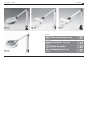
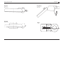
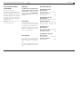
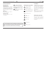
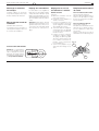
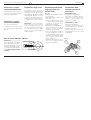
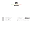
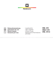
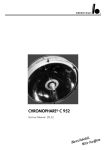
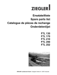
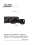
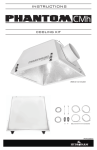
Waldmann
D
GB
F
I
Gebrauchsanweisung
Instructions for use
Mode d‘emploi
Istruzioni per l‘uso
Modelle
Models
Modèles
Modelli
AVL 122 N
FGL 111/118
LX 111
RLL 122/122 T
AVL / FGL / LX / RLL
Waldmann
Fig. 1a
Fig. 1b
Fig. 1c
RLL 122 T
FGL 118
LX 111
Original
D
Gebrauchsanweisung
4
Translations
Fig. 1d
AVL 122 N
2
GB Instructions for use
7
F
Mode d‘emploi
10
I
Istruzioni per l‘uso
13
AVL / FGL / LX / RLL
Waldmann
Fig. 2a
Fig. 2b/c
RLL 122 T
FGL / LX
Fig. 2d
15°
Fig.3
15°
AVL 122 N
3
Gebrauchsanweisung AVL / FGL / LX / RLL
D
Waldmann
Allgemeines
Bestimmungsgemäßer
Gebrauch:
Verwendungszweck:
Arbeitsplatzleuchte mit integrierter
Lupe oder Ventilator - Arbeitsplatzleuchten sind Leuchten für die
Einzelplatzbeleuchtung und werden zusätzlich zu einer allgemeinen
Beleuchtung verwendet
Montage
Sicherheitshinweise :
Abkürzungen und Symbole:
Die Leuchte darf nur in trockenen
und nicht explosionsgefährdeten
Räumen betrieben werden!
Achtung,
Begleitpapiere beachten!
Bei Nichtbenutzung die Lupe
gegen Sonneneinstrahlung
abdecken. Brandgefahr!
Schutzleiteranschluss
(Gerät der Schutzklasse I)
Gerät der Schutzklasse II
(Schutzisolation)
Einsatzort:
Ausschließlich für trockene und
nicht explosionsgefährdete Räume.
Wechselstrom
Die Leuchte muss mittels Tischklemme oder Tischfuß standsicher
an der Arbeitsfläche positioniert
werden.
Die Befestigungslöcher am Federfußgelenk werden zugänglich, indem man die Befestigungsplatte
(3) um 45° dreht.
Hinweis: Styropor im Leuchtenkörper dient der Transportsicherung
der Lampe und kann entfernt werden.
AUS
(Lampenstromkreis)
Betriebsart:
Die Leuchte ist ausgelegt für Dauerbetrieb.
EIN
(Lampenstromkreis)
Inbetriebnahme
Brandgefahr!
DVE
Der Hersteller kann nicht für Schäden verantwortlich gemacht
werden, die infolge der Nutzung abweichend vom bestimmungsgemäßen Gebrauch, oder der Nichtbeachtung von
Sicherheitshinweisen und Warnungen, verursacht werden.
4
VDE-Zulassung
CEKonformitätskennzeichen
Vor Inbetriebnahme ist zu überprüfen, ob die Anschlussspannung mit
der auf dem Leistungsschild angegebenen Nennspannung übereinstimmt.
Gebrauchsanweisung AVL / FGL / LX / RLL
Ein- und Ausschalten des
Leuchtmittels
Mit dem Schalter, oben auf dem
Reflektorgehäuse, wird die Lampe
ein- und ausgeschaltet.
Ein- und Ausschalten des
Ventilators (nur bei Leuchte AVL)
Mit dem Schalter, oben auf der
Ventilatorabdeckung wird der Ventilator ein- und ausgeschaltet.
D
Nachstellen der Gelenke
Die Gelenke sind mittels einer Verstellschraube einstellbar. Jedes Gelenk wird so eingestellt, dass die
Leuchte einerseits leicht beweglich
ist, andererseits aber das Gelenk
in der gewünschten Einstellung verharrt. Die Leuchte ist somit fixiert.
Vorsicht! Das Fußgelenk darf nur
festgestellt oder leicht gelöst werden, ansonsten hängt die
Entlastungsfeder aus und muss
werkseitig wieder eingestellt werden.
Tischfüße 190 036 oder 190 037
Einstellen der Feder bei
Federgelenk-Leuchten
Lampen- und Starterwechsel
a) Leuchte bis zum Anschlag nach
hinten kippen.
b) Die Flügelmutter (1) etwa 3-4
Umdrehungen lösen.
c) Die Flügelmutter (1) nach innen
drücken, bis die gegenüberliegende Stellscheibe (2) aus dem
Haltestift rastet.
d) Stellscheibe (2) mit einem flachen Gegenstand (auch große
Münze) zum Spannen der Feder
nach links drehen.
e) Stellscheibe (2) nach Erreichen
der gewünschten Spannung
durch kurzes Vor- und Rückdrehen zum Einrasten in den
Haltestift bringen. Dabei die
Flügelmutter (1) leicht anziehen.
f) Flügelmutter (1) bis zur erforderlichen Bremswirkung anziehen.
Bei den Leuchten AVL und RLL:
Siehe Fig. 2d und 2a auf Seite 3.
Nach Lösen der Befestigungsschrauben für die Blende, kann diese abgenommen werden. Die
Leuchtstofflampe und der Starter
sind jetzt zugänglich (siehe Fig. 2a
und 2b).
Bei den Leuchten FGL, LX:
Siehe Fig. 2b/c auf Seite 3.
Den Schraubendreher in die Aussparungen
zwischen
dem
Reflektorgehäuse und der Blende
stecken und nach oben drücken.
Die Leuchtstofflampe in Längsrichtung aus der Lampenfassung ziehen.
1
15°
2
15°
Achtung: Bei der Verwendung
dieser Tischfüße dürfen die
Leuchten nur um ca. 15 ° aus
der Mittelstellung gedreht werden. Es besteht sonst Kippgefahr!
Waldmann
3
5
Gebrauchsanweisung AVL / FGL / LX / RLL
Auswechseln des Filters
am Ventilator
(nur bei Leuchte AVL)
Abnehmen der Blende durch Lösen
der Befestigungsschrauben. Durch
leichtes Eindrücken an den
Befestigungspunkten der Filterabdeckung, kann diese samt Filter
herausgenommen und wieder eingesetzt werden.
Vorsicht! Der Ventilator muss hierzu ausgeschaltet sein.
D
Waldmann
Wartung
Technische Daten
Vor Wartungs- und Reparaturarbeiten ist die Leuchte vom Netz
zu trennen! Die Arbeiten dürfen
nur von einem ausgebildeten
Elektro-Fachmann durchgeführt
werden!
Leuchte AVL 122 N
Abmessungen
Leuchtenkörper
∅ 247 mm
Lampenbestückung
Ring-LS-Lampe
22 W
Leuchte FGL 111/118
Reinigung
Zur Reinigung der Leuchtenteile
verwenden Sie ein mit normalem
Haushaltsreiniger getränktes Tuch.
Beachten Sie bei den verwendeten
Mitteln die Verträglichkeit mit Lacken und Kunststoffen.
Abmessungen
Leuchtenkörp. 270 x 67 x 52 mm
Lampenbestückung
Komp.-LS-Lampe 11 W (FGL 111)
Komp.-LS-Lampe 18 W (FGL 118)
Leuchte LX 111
Abmessungen
Leuchtenkörp. 270 x 67 x 52 mm
Lampenbestückung
Kompakt-LS-Lampe
11 W
Leuchte RLL 122/122T
Entsorgung
Die Leuchte muss nach Ende der
Lebensdauer, entsprechend den örtlichen Vorschriften, entsorgt werden.
Defekte Leuchtstofflampen müssen als Sondermüll entsorgt werden.
6
Abmessungen
Leuchtenkörper
∅ 245 mm
Lampenbestückung
Ring-LS-Lampe
22 W
Instructions for use AVL / FGL / LX / RLL
GB
Waldmann
Installation
General information
Designated use:
Intended purpose:
Work place light with integrated
magnifying glass or with ventilator
- Work place lights are lights for single workplaces and are used in addition to the ambient room lighting
system.
Safety instructions:
Abbreviations and symbols:
The light may only be operated in
dry rooms not subject to explosion hazards!
Attention: observe
accompanying documents!
When not in use, cover the
magnifier against solar radiation. Risk of fire!
Protective earthing
(Device of protection class I)
Device of protection class
II (protective insulation)
Place of use:
Only in dry rooms not subject to
the risk of explosion.
Note: Polystyrene in the light body
is used for transport safety of the
lamp and can be removed.
Alternating current
Operating mode:
The light is designed for continuous operation.
OFF
(lamp circuit)
ON
(lamp circuit)
Risk of fire!
DVE
The manufacturer cannot be held liable for damage caused
by using the device for purposes other than the designated
use or by ignoring safety instructions and warnings.
The light must be positioned firmly
and stably on the work surface using the desk clamp or table base.
You can gain access to the mounting holes on the spring-balanced
base by turning the mounting plate
(3) through 45 °.
Putting into operation
Before putting the light into
operation, check that the
connection voltage corresponds to
the rated voltage specified on the
rating plate.
VDE Approval
CEconformity mark
7
Instructions for use AVL / FGL / LX / RLL
GB
Waldmann
Switching the lamp on
and off
Readjusting the articulation joints
Adjusting the spring on
spring-balanced lights
Changing the lamp and
starter unit
The lamp can be switched on and
off at the switch on the top of the
reflector housing.
The articulation joints can be adjusted by means of an adjusting
screw. Each articulation joint must
be adjusted so that the light is easy
to move on the one hand but so
that the articulation joint remains
in the required position on the
other. This fixes the light in position.
a) Tilt the light fully back.
b) Slacken the wing nut (1) approx.
3-4 turns.
c) Push the wing nut (1) in until the
opposite adjusting disk (2) disengages from the retaining pin.
d) Turn the adjusting disk (2) with a
flat implement (or a large coin)
to the left in order to cock the
spring.
e) When the required tension has
been reached, engage the adjusting disk (2) into the retaining
pin by turning it briefly forwards
and backwards until it engages
in position. Lightly tighten the
wing nut (1) when doing this.
f) Tighten the wing nut (1) until the
required breaking effect is
achieved.
On lights AVL and RLL:
See fig. 2d and 2a on page 3.
Undo the securing screws for the
cover and you can then detach the
cover. You will now have access to
the fluorescent lamp and the
starter unit.
Switching the ventilator on
and off
(only on light AVL)
The ventilator can be switched on
and off at the switch on the top of
the ventilator cover.
Caution! The base articulation joint
may only be locked or slackened
lightly. Otherwise, the relief spring
will be disengaged and must be set
again at the works.
8
15°
15°
Important: If using these table
bases, the light may be turned
only through approx. 15 ° from
centre position. Otherwise
there is a risk of the light tipping over!
1
2
Table bases 190 036 or 190 037
3
On lights FGL, LX, SNL:
See fig. 2b/c on page 3.
Insert the screwdriver into the recesses between the reflector housing and the cover and push it up.
Pull the fluorescent lamp lengthwise out of the lamp socket.
Instructions for use AVL / FGL / LX / RLL
Changing the filter on the
ventilator (only on light AVL)
Detach the cover by undoing the
securing screws. By pressing in
lightly at the securing points of the
filter cover, you can detach the filter cover, together with the filter,
and refit it.
Caution! Switch off the ventilator
before doing this.
GB
Waldmann
Maintenance
Technical data
Disconnect the light from the
electrical power supply before
carrying out maintenance or repair work! This work may be carried out only by a qualified electrician!
Light AVL 122 N
Dimensions
Light body
∅ 247 mm
Lamp complement
Circular fluorescent lamp
22 W
Light FGL 111/118
Cleaning
Please use a cloth and normal domestic cleaning agent to clean the
light components.
Please ensure that the cleaning
agents which you use are compatible with paints and plastics.
Dimensions
Light body
270 x 67 x 52 mm
Lamp complement
Comp. fluor. lamp 11 W (FGL 111)
Comp. fluor. lamp 18 W (FGL 118)
Light LX 111
Dimensions
Light body
270 x 67 x 52 mm
Lamp complement
Compact fluorescent lamp
11 W
Light RLL 122/122T
Waste disposal
When it reaches the end of its service life, the light must be disposed
of in accordance with local regulations.
Dimensions
Light body
∅ 245 mm
Lamp complement
Circular fluorescent lamp
22 W
Defective fluorescent lamps must
be disposed of as hazardous waste.
9
Mode d‘employ AVL / FGL / LX / RLL
F
Waldmann
Montage
Généralités
Utilisation conforme à
l’emploi prévu :
Application :
Luminaire pour poste de travail
avec loupe ou avec ventilateur - Les
luminaires pour poste de travail
sont des luminaires destinés à
l‘éclairage d‘un poste de travail individuel et sont utilisés en complément de l‘éclairage général.
Consignes de sécurité :
Abréviations et symboles :
Le luminaire ne doit être utilisé que
dans des locaux secs et exempts
de risques d’explosion !
Attention, tenir compte
des documents d’accompagnement !
Lorsque le luminaire n’est
pas utilisé, protéger la loupe
contre le rayonnement solaire en la
couvrant. Risque d’incendie !
Raccordement avec fil de
terre (Appareil de la classe
de protection I)
Appareil de la classe de
protection II
(double isolation)
Lieu d’application :
Le luminaire ne doit être utilisé que
dans des pièces sèches et exemptes de risques d’explosion.
ARRÊT
(circuit lampe)
MARCHE
(circuit lampe)
Risque d’incendie !
DVE
10
Remarque: le polystyrène dans le
corps de lampe sert à protéger la
lampe pendant le transport et peut
être enlevé.
Courant alternatif
Type de fonctionnement :
Le luminaire est conçu pour le fonctionnement en service continu.
Le fabricant décline toute responsabilité concernant les dommages qui résulteraient d’une utilisation non conforme à l’emploi prévu ou du non-respect des consignes de sécurité et
des avertissements.
La lampe doit être positionée de
façon stable sur le plan de travail au
moyen d‘une pince ou d‘un socle
de table.
Les trous de fixation sur l‘articulation de pied à ressort sont accessibles en tournant la plaque de fixation (3) en 45°.
Homologation VDE
Sigle de conformité CE
Mise en service
Avant la mise en service, il est nécessaire de vérifier que la tension
d‘alimentation correspond à la tension nominale indiquée sur la plaquette signalétique.
Mode d‘employ AVL / FGL / LX / RLL
Allumage et extinction
de la lampe
La lampe s‘allume et s‘éteint au
moyen de l‘interrupteur situé sur le
dessus du boîtier de réflecteur.
Mise en marche et arrêt du
ventilateur
(luminaire AVL seulement)
Le ventilateur se met en marche et
s´arrête par l‘interrupteur situé sur
le couvercle de ventilateur.
F
Waldmann
Réglage des articulations
Les articulations sont réglables à
l‘aide d‘une vis de réglage. Régler
chaque articulation de façon que la
lampe soit facile à déplacer tout en
étant suffisamment résistante pour
être immobilisée dans la position
voulue.
Attention! L‘articulation de pied
doit être seulement bloquée ou légèrement desserrée, sinon le ressort se décroche et la lampe devra
être retournée en usine pour réglage.
Pour les luminaires AVL et RLL:
Voir fig. 2d et 2a de page 3.
Retirer le diffuseur après avoir desserré ses vis de fixation. Le tube
fluorescent et le starter sont à présent accessibles.
Pour les luminaires FGL, LX:
Voir fig. 2b/c de page 3.
Introduire un tournevis dans les évidements entre le boîtier de réflecteur et le diffuseur et faire levier
vers le haut.
Retirer le tube fluorescent de la
douille dans le sens de la longueur.
Fig. 4
1
2
15°
Attention: en cas d‘utilisation
de ce socle de table, le luminaire ne doit pas être tournée
de plus de 15° de part et d‘autre
de la position centrale. Sinon, il
y a risque de basculement!
Voir fig. 4
a) Basculer le luminaire vers l‘arrière jusqu‘en butée.
b) Desserrer l‘écrou papillon (1)
d‘environ 3-4 tours.
c) Posser l‘écrou papillon (1) vers
l‘intérieur jusqu‘à ce que le disque de réglage (2) soit dégagé
de la goupille de retenue.
d) Tourner le disque de réglage (2
vers la gauche avec un objet plat
(ou une pièce de monnaie) pour
tendre le ressort.
e) Lorsque la tension souhaitée
est atteinte, engager le disque
de réglage (2) dans la goupille
de retenue par une brève rotation en avant et en arrière. Ce
faisant, serrer légèrement
l‘écrou papillon (1).
f) Serrer l‘écrou papillon (1) jusqu‘à l‘effet de freinage nécessaire.
Remplacement du tube et
du starter
15°
Socle de table 190 036 003
Réglage du ressort sur
les luminaires à articulation à ressort
3
11
Mode d‘employ AVL / FGL / LX / RLL
Remplacement du filtre
de ventilateur
(luminaire AVL seulement)
Retirer le diffuseur en desserrant
ses vis de fixation.
Une légère pression exercée sur
les points de fixation du couvercle
de filtre permet de le retirer avec
le filtre, puis de le remettre en
place.
Attention: Le ventilateur doit être
hors tension.
F
Waldmann
Maintenance
Caractéristiques techniques
Déconnecter le luminaire du secteur avant toute opération de
maintenance ou de réparation.
Les travaux ne doivent être effectués que par un électricien qualifié.
Luminaire AVL 122 N
Dimensions
Corps de lampe
Equipement
Tube fluo circulaire
∅ 247 mm
22 W
Luminaire FGL 111/118
Nettoyage
Le luminaire se nettoie à l‘aide d‘un
chiffon imbibé d‘un produit ménager usuel.
Assurez-vous que les produits utilisés sont compatibles avec les laques et les plastiques.
Dimensions
Corps de lampe270 x 67 x 52 mm
Equipement
Tube fluo compact 11 W (FGL 111)
Tube fluo compact 18 W (FGL 118)
Luminaire LX 111
Dimensions
Corps de lampe270 x 67 x 52 mm
Equipement
Tube fluo compact
11 W
Luminaire RLL 122/122T
Elimination
Au terme de sa durée de vie, l‘appareil doit être éliminé conformément aux dispositions locales.
Les tubes fluorescents défectueux
doivent être éliminés en tant que
déchets spéciaux.
12
Dimensions
Corps de lampe
Equipement
Tube fluo circulaire
∅ 245 mm
22 W
Istruzioni per l’uso AVL / FGL / LX / RLL
I
Waldmann
Informazioni generali
Uso conforme allo scopo
d’impiego previsto:
Scopo d’impiego:
Apparecchio illuminante per posto
di lavoro con lente integrata o con
ventilatore - Apparecchi per posti
di lavoro sono destinati per un posto di lavoro singolo e sono utilizzati in aggiunta ad una illuminazione generale.
Luogo d’impiego:
Esclusivamente per locali asciutti e
non soggetti a pericolo d’esplosione.
Montaggio
Avvertenze per la
sicurezza:
Abbreviazioni e simboli:
Attenzione, osservare la
documentazione in
dotazione!
La lampada deve essere utilizzata
esclusivamente in locali asciutti e
non soggetti a pericolo d’esplosione!
Conduttore di protezione
(Apparecchio della classe
di protezione I)
Se non viene utilizzata, proteggere la lente dall’esposizione ai raggi solari. Pericolo di
incendio!
Apparecchio della classe di
protezione II
(Isolamento di protezione)
Corrente alternata
Avvertenza: il polistirolo nel corpo
dell’apparecchio ha soltanto una
funzione di protezione durante il
trasporto e va quindi tolto.
OFF
(circuito elettrico della
lampada)
Tipo di funzionamento:
L’apparecchio d’illuminazione è predisposto al funzionamento continuo.
ON
(circuito elettrico della
lampada)
Pericolo di incendio!
Il fabbricante non può rispondere di danni causati da un utilizzo non conforme allo scopo d’impiego previsto o della
mancata osservanza delle avvertenze di sicurezza e degli avvertimenti.
L’apparecchio va fissato in maniera
stabile al piano di lavoro per mezzo
di un morsetto da tavolo o di un’apposita base.
I fori per il fissaggio dell’apparecchio, situati nello snodo a molla
della base, sono accessibili
ruotando la piastra di fissaggio (3)
di 45°.
DVE
Messa in funzione
Prima della messa in funzione occorre verificare che la tensione di
allacciamento coincida con la tensione nominale indicata sulla
targhetta del consumo dell’apparecchio.
Omologazione VDE
CE-Contrassegno di
conformità
13
Istruzioni per l’uso AVL / FGL / LX / RLL
Accensione e spegnimento dell’apparecchio
La lampada può essere accesa o
spenta per mezzo dell’interruttore
situato sul portariflettore
Accensione e spegnimento del ventilatore
(solo per il modello AVL)
Il ventilatore si accende e si spegne con l’interruttore sulla copertura in alto.
I
Waldmann
Regolazione degli snodi
Gli snodi sono muniti di una vite
regolabile che ne permette il fissaggio. In questo modo, se da un lato
viene garantita la perfetta movibilità
della lampada, dall’altro lo snodo
viene bloccato nella posizione desiderata permettendo di mantenere l’apparecchio in una posizione
fissa.
Attenzione: lo snodo della base
deve essere fisso e può essere allentato solo leggermente, per evitare che la molla di compensazione esca dalla sua sede e debba
quindi essere nuovamente regolata dal costruttore.
Vedi fig. 4
a) Ribaltare la lampada all’indietro
fino all’arresto.
b) Allentare il dado ad alette (1) di
3-4 rotazioni ca.
c) Premere il dado ad alette (1) verso l’interno finché la rosetta di
regolazione (2) di fronte esce
dalla spina di fissaggio.
d) Ruotare la rosetta di regolazione
(2) verso sinistra con un oggetto
piatto (p. es. una moneta grossa) per tendere la molla.
e) Una volta raggiunto il grado di
tensione desiderato, ruotare la
rosetta (2) nelle due direzioni fino
all’arresto nella spina di fissaggio, serrando leggermente il
dado ad alette (1).
f) Serrare il dado ad alette (1) finché non si è raggiunto l’effetto
di arresto desiderato.
Modelli AVL e RLL:
Vedi fig 2d e 2a de pagina 3.
Per rendere accessibili il tubo fluorescente e il relè di accensione,
svitare le viti di fissaggio dello
schermo e smontarlo.
Modelli FGL, LX, SNL:
Vedi fig 2b/c de pagina 3.
Inserire un cacciavite nelle fessure
tra il porta-riflettore e lo schermo e
fare leva verso l’alto.
Estrarre il tubo fluorescente dal
portalampada nel senso della
longitudinale.
Fig. 4
1
2
15°
Attenzione: se si sono scelti
questi tipi di base per appoggiare l’apparecchio sul tavolo,
ruotare la lampada di ca. 15° al
massimo rispetto alla posizione centrale per evitare qualunque rischio che l’apparecchio
si ribalti.
Sostituzione della
lampada e del relè di
accensione
15°
Basi da tavolo 190 036 o 190 037
Regolazione della molla
negli apparecchi con
snodi a molla
3
14
Istruzioni per l’uso AVL / FGL / LX / RLL
Sostituzione del filtro nel
ventilatore
(solo per il modello AVL)
Svitare le viti di fissaggio ed estrarre lo schermo. Premendo leggermente sui punti di fissaggio della
copertura del filtro sarà possibile
estrarre quest’ultima insieme al filtro e quindi reinserirla.
Attenzione: il ventilatore deve essere spento!
I
Waldmann
Manutenzione
Dati tecnici
Prima di procedere a operazioni
di manutenzione o riparazione,
sfilare la spina dell’apparecchio!
Queste operazioni devono essere
effettuate soltanto da personale
specializzato addestrato da noi.
Modello AVL 122 N
Dimensioni
Corpo della lampada ∅ 247 mm
Equipaggiamento
Circolina fluorescente
22 W
Modello FGL 111/118
Pulizia
Per la pulizia delle parti dell’apparecchio utilizzare un panno inumidito con un normale prodotto di uso
domestico.
Assicurarsi che il prodotto utilizzato non sia dannoso per vernici e
materie plastiche.
Dimensioni
Corpo della lampada
270 x 67 x 52 mm
Equipaggiamento
Tubo fluorescente compatto
11 W (FGL 111)
Tubo fluorescente compatto
18 W (FGL 118)
Modello LX 111
Dimensioni
Corpo della lampada
270 x 67 x 52 mm
Equipaggiamento
Tubo fluorescente compatto 11 W
Smaltimento
Una volta scaduta la validità dell’apparecchio, esso va smaltito in conformità con le disposizioni di legge
locali sullo smaltimento dei rifiuti.
Modello RLL 122/122T
Dimensioni
Corpo della lampada ∅ 245 mm
Equipaggiamento
Circolina fluorescente
22 W
I tubi fluorescenti difettosi vanno
considerati rifiuti speciali.
15
Waldmann Lichttechnik
16
Ausgabe: 01.05.2002
Best.-Nr. 406 004 770 - ©copyright H.Waldmann GmbH & Co. KG - nB/05/02 TB - Änderungen vorbehalten - Printed in Germany
AVL / FGL / LX / RLL
Waldmann