1
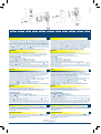
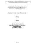
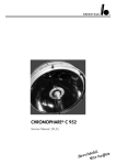
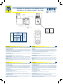
E L E T T R O VA LV O L E - E L E C T R O VA N N E S - S O L E N O I D VA LV E S - M A G N E T V E N T I L E
ISTRUZIONI DI INSTALLAZIONE, USO E MANUTENZIONE PER ELETTROMAGNETE
INSTRUCTIONS FOR INSTALLATION, USE AND MAINTENANCE OF COIL
INSTRUCTIONS DE MISE EN SERVICE ET D’ENTRETIEN DE LA BOBINE
INBETRIEBNAHME- UND WARTUNGSANLEITUNG - MAGNETSPULE
TM
ZB19A
II 3D - T 110°C
DO NOT SEPARATE
WHEN ENERGIZED
II 3D Ex Tc IIIC Dc
IP65 X T110° C
TYPE ZB19A
V 24 DC
W 5.5
ED: 100.
T. amb. max. 50° C
T. cable 55° C
Coppia di serraggio
Tightening torque
Couples de serrage
_ 0,1 N/m
0,6 +
Anzugsmoment
Assorbimento
Power Absorption
Absorption
Leistungsaufnahme
c.a.
AC
(VA)
Tipo
Type
ZB19A
Spunto
Inrush
Appel
Anzug
Esercizio
Holding
Service
Betrieb
12
6
c.c.
DC
(W)
5,5
Peso
Weight
Poid
Gewicht
(kg)
0,08
DESCRIZIONE
IT
DESCRIPTION
EN
Le seguenti istruzioni relative all'elettromagnete ZB19A completo di connettore, sono un supplemento al foglio di
istruzioni allegato ad ogni elettrovalvola. Utilizzare sempre entrambi i fogli di istruzione per l'installazione, uso e
manutenzione di un'elettrovalvola.
The following instructions for coil ZB19A equipped with connector, are a supplement to the instruction sheet
supplied with each solenoid valve. Always use both instruction sheets for installation, use and maintenance of a
solenoid valve.
CARATTERISTICHE GENERALI - Elettromagnete e connettore adatti per utilizzo in atmosfere esplosive polverose (zona 22) secondo
Direttiva ATEX 94/9/EC. Il prodotto risponde ai requisiti essenziali di Sicurezza e Salute secondo l'allegato II paragrafo 2.3 della
Direttiva ATEX, in quanto conforme alle norme europee EN 60079-0:2009; EN 60079-31:2009. Conforme ai requisiti essenziali delle
direttive: 73/23/EC (Bassa tensione), 2004/108/EC (EMC) e successive modifiche.
GENERAL FEATURES - Coil and connector intended for use in dusty explosive atmospheres (zone 22) according to Directive ATEX
94/9/EC. The product complies with the essential Safety and Health requirements as per annex II, § 2.3 of ATEX Directives since it is
in conformity with the European Standards EN 60079-0:2009; EN 60079-31:2009. It also complies with essential requirements of
Directives 73/23/EC (low voltage), 2004/108/EC (EMC) and their subsequent updates.
CONNESSIONI ELETTRICHE - Innesto rapido 6,3 x 0,8 (DIN 46340), 2 Attacchi di linea e 1 presa di terra. ZB19A: completo di
connettore PG9 (adatto per cavo Ø 5-7 mm).
ELECTRIC CONNECTIONS - Spade terminals 6,3 x 0,8 (DIN46340), 2 line+1 earth terminals. ZB19A: complete with
connector Pg9 (suitable forØ 5-7mmcable).
MATERIALI DI INGLOBAMENTO - PET (Polietilene tereftalato) caricato vetro; colore nero.
ENCAPSULATION MATERIALS - PET (Polyethylene terephtalate) fiberglass reinforced; black colour.
CARATTERISTICHE TECNICHE - Servizio continuo: ED 100%. Temperatura superficiale massima: 110°C. Temperatura ambiente: 10°C +50°C. Grado di protezione: IP 65 (EN 60529) con connettore. Tensioni c.c.: 12-24V (+10% -5%). Tensioni c.a.: 24V-110V230V/50-60Hz (+10% -15%).
TECHNICAL FEATURES - Continuous duty: ED 100%. Max. surface temperature: 110°C. Ambient temperature: -10°C +50°C.
Protection degree: IP65 (EN 60529) with plug connector. Voltages DC: 12-24V (+10% -5%). Voltages AC : 24V-110V- 230V/5060Hz (+10% -15%).
ATTENZIONE: l’impiego dell'elettromagnete al di fuori delle specifiche riportate sulla documentazione tecnica o la non osservanza
delle norme di uso e manutenzione sollevano automaticamente il costruttore da qualsiasi responsabilità o danno causato da un non
corretto funzionamento del dispositivo.
WARNING: the manufacturer assumes no responsibility for damage caused by improper operation of the solenoid valves if
operated beyond the specifications stated in the data sheet or not in accordance with the manufacturers use and maintenance
instructions.
DESCRIPTION
FR
BESCHREIBUNG
DE
Les instructions suivantes concernant la bobine ZB19A équipée de connecteur complètent la notice d'emploi
accompagnant claque électrovanne. Utiliser toujours les deux notices d'emploi pour l'installation, l'utilisation et
l'entretien de l'électrovanne.
Die folgenden Betriebsanleitungen für die Magnetspule ZB19A, komplett mit Stecker, sind eine Ergänzung der
mit den Magnetventilen mitgelieferten Anleitung. Für Einbau, Bedienung und Wartung der Magnetventile
immer beide Anleitungen beachten
CARACTERISTIQUES GENERALES - Bobine et connecteur destinés à être utilisés en atmosphères explosibles poussiéreuses
(zone 22) selon Directive ATEX 94/9/EC. Le produit correspond aux conditions requises essentielles de Sécurité et Santé selon
l'annexe II, § 2.3 des directives ATEX car il est conforme aux normes européennes EN 60079-0:2009; EN 60079-31:2009. Il est
aussi conforme aux conditions requises essentielles des directives 73/23/EC (basse tension), 2004/108/EC (EMC) et leurs
modifications successives.
ALLGEMEINE MERKMALE - Magnetspule und Stecker geeignet zum Einsatz in staubiger, explosionsgefährdeter Umgebung
(Zone 22) nach der Richtlinie ATEX 94/9/EC. Das Gerät entspricht den Sicherheits- und Gesundheitsanforderungen im Einklang
mit der Anlage II, Par. 2.3 der ATEX-Richtlinie, da übereinstimmend mit den europäischen Normen EN 60079-0:2009;
EN 60079-31:2009. Konform mit den wesentlichen Anforderungen der Richtlinien: 73/23/EC (Kleinspannung), 2004/108/EC
(EMC) und nachfolgenden Änderungen.
RACCORDEMENTS ELECTRIQUES - Connexion rapide 6,3 x 0,8 (DIN 46340), 2 raccords de ligne et 1 prise de terre. ZB19A
completo di connettore PG9 (adatto per cavo Ø 5-7 mm).
ELEKTRISCHE ANSCHLÜSSE - Schnellkupplung 6,3 x 0,8 (DIN 46340), 2 Netzanschlüsse und 1 Erdanschluss. ZB19A completo di
connettore PG9 (adatto per cavo Ø 5-7 mm).
MATERIAUX DE SURMOULAGE - PET (Polyéthylène téréphtalate) renforcé par des fibres de verre ; couleur noir.
EINBETTUNGSMATERIAL: - glasfaserverstärktes PET (Polyethylenterephthalat); schwarz.
CARACTERISTIQUES TECNIQUES - Service continu : ED 100%. Température superficielle max: 110°C. Température ambiante:
-10°C +50°C. Indice de protection: IP 65 (EN 60529) avec connecteur. Tensions c.c . : 12-24V (+10% -5%). Tensions c.a. : 24V110V- 230V/50-60Hz (+10% -15%).
TECHNISCHE DATEN - Dauerbetrieb: ED 100%. Max. Oberflächentemperatur: 110°C. Umgebungstemperatur: -10°C +50°C.
Schutzklasse: IP 65 (EN 60529) mit Stecker.
Gleichspannung: 12-24V (+10% -5%). Wechselspannung: 24V-110V- 230V/50-60Hz (+10% -15%).
ATTENTION: une utilisation de la bobine non conforme aux spécifications indiquées sur la documentation technique ou le nonrespect des normes d'utilisation et d'entretien dégagent automatiquement le constructeur de toute responsabilité et/ou en cas de
dommage dérivant d'un fonctionnement erroné du dispositif.
ACHTUNG: ein Einsatz der Magnetspule für nicht in der technischen Dokumentation angegebene Verwendungszwecke oder die
Nichtbeachtung der Bedienungs- und Wartungsanleitungen enthebt den Hersteller automatisch jeder Verantwortung für
Folgeschäden und/oder ein mangelndes Funktionieren des Geräts.
U2704000033-1412
1
2
3
4
5
6
7
8
9
10
11
Elettromagnete
Guarnizione
Portacontatti
Protezione
O-Ring
Vite di fissaggio connettore
Pressacavo
Rondella
Serracavo
Terminali di linea
Terminale di terra
Earth terminal
Coil
Gasket
Terminal block
Housing
O-Ring
Plug connector fixing screw
Grommet
Washer
Gland-nut
Line terminals
Bobine
Garniture
Porte-contacts
Protection
O-Ring
Vis de fixation de connecteur
Presse-câble
Rondelle
Serre-câble
Bornes de ligne
Bornes de tere
Magnetspule
Dichtung
Kontaktblock
Gehäuse
O-Ring
Befestigungsschraube Stecker
Klemmring
Unterlegscheibe
Kabelverschraubung
Netzanschlüsse
Erdungsanschluss
IT
INSTALLAZIONE
Il cablaggio deve essere conforme ai regolamenti locali e nazionali per le apparecchiature per atmosfere pericolose. Verificare che i
valori di tensione e frequenza stampigliati sull'elettromagnete corrispondano a quelli di linea. L'elettromagnete deve essere protetto
con un fusibile adeguato alla corrente nominale. Il potere di interruzione del fusibile deve essere adeguato alla possibile corrente di
corto circuito della rete di alimentazione. Le elettrovalvole devono essere collegate ad un impianto di terra a seconda della tensione e
delle Norme locali. Non collegare elettricamente l'elettromagnete se questo non è montato sull'elettrovalvola. ZB19A: per effettuare
la connessione ai terminali dell'elettromagnete usare un cavo appropriato alla temperatura ambiente ed alla potenza assorbita,
rimuovere la protezione 4 del connettore. Rimuovere la guaina esterna del cavo e l'isolante dei fili. Collegare i fili di linea ai
terminali 10 del connettore ed il filo di terra al terminale di terra 11 . Evitare una eccessiva trazione dei fili tra i terminali ed il
serracavo. Assemblare il serracavo 9 in modo che il pressacavo 7 aderisca perfettamente intorno al cavo. Riposizionare la
_ 0,1 N/m.
protezione 4 . ZB19A : serrare la vite 6 con coppia di serraggio = 0,6 +
! È NECESSARIA UNA PROTEZIONE AGGIUNTIVA PER PROTEGGERE LA BOBINA CONTRO URTI MECCANICI O LUCE UV.
EN
INSTALLATION
The cabling must be in accordance with local and national legislation for equipment for dangerous environments.Check that the
voltage and frequency printed on the coil correspond to the mains.The coil must be protected by a fuse appropriate for the nominal
current. The interruption level of the fuse must be appropriate for the possible short circuit current of the power mains. The solenoid
valves must be connected to an earth in accordance with the voltage and local legislation. Do not electrically connect the coil if it is not
assembled on the solenoid valve. ZB19A: to make a connection to the coil terminals use a cable appropriate for the environmental
temperature and the current drawn. Remove housing 4 of the connector. Remove the external sheath of the cable and the insulation
of the wires. Connect the line wires to the terminals 10 of the connector and the earth wire to the earth terminal 11 . Make sure the
wires don't pull between the terminals and the gland-nut. Assemble the gland-nut 9 so that the grommet 7 seals perfectly around
_ 0,1 N/m.
the cable. Replace the housing 4 . ZB19A: and tighten the screw 6 with a tightening torque = 0,6 +
! ADDITIONAL PROTECTION IS NECESSARY TO PROTECT COIL AGAINST MECHANICAL IMPACT OR UV LIGHT.
MAINTENANCE
MANUTENZIONE
Una buona manutenzione mantiene nel tempo affidabilità e funzionalità del prodotto.
Durante le azioni di manutenzione curare al massimo la pulizia, disconnettere sempre la tensione di alimentazione e non
alimentare mai, per nessun motivo, l'elettromagnete senza che quest'ultimo sia correttamente montato sulla valvola completa.
Utilizzare sempre ricambi originali SIRAI , non modificare arbitrariamente alcun componente della bobina.
SOSTITUZIONE ELETTROMAGNETE
1) Disconnettere l'alimentazione dell'elettromagnete
2) Allentare la vite H e disconnettere il connettore F dall'elettromagnete D .
3) Rimuovere la clip C di blocco elettromagnete (o il dado per i modelli in cui è previsto).
4) Sostituire l'elettromagnete D (verificare che i valori di voltaggio e frequenza stampigliati sul nuovo elettromagnete corrispondano
a quelli di linea).
5) Riassemblare i suddetti componenti (prestare particolare attenzione al corretto inserimento della guarnizione E nella propria
_ 0,1 N/m.
sede). Serrare la vite H con una coppia di serraggio = 0,6 +
NOTE PER L’EVENTUALE SMALTIMENTO: Lo smaltimento del prodotto deve essere effettuato secondo quanto previsto da DPR n.
915/82 dalle Direttive CEE n. 75/442, n. 76/403, n. 78/319, ulteriori modifiche, aggiornamenti ed eventuali normative regionali. Si
raccomanda di controllare la coppia di serraggio della vite e del pressacavo regolarmente, ripristinarle al valore originale se necessario.
TM
FR
INSTALLATION
Le câblage doit être conforme aux réglementations locales et nationales pour les appareils en atmosphères dangereuses. Utiliser
un câble approprié aux températures ambiantes et à la puissance absorbée. Vérifier que les valeurs de tension et de fréquence
estampillées sur la bobine correspondent aux valeurs de la ligne. La bobine doit être protégée par un fusible adéquat au courant
nominal. Le pouvoir d'interruption du fusible doit être approprié au courant possible de court-circuit du réseau d'alimentation.
Les électrovannes doivent être connectées à une installation à la terre selon la tension et les Normes locales.
Ne pas connecter électriquement la bobine si elle n'est pas montée sur l'électrovanne.
Pour effectuer la connexion aux bornes de l'électrovanne, enlever la protection 4 du connecteur. Enlever la gaine externe du câble
et l'isolant des fils. Connecter les fils de ligne aux bornes 10 du connecteur et le fil de terre à la borne de terre 11 .
Éviter une traction excessive des fils entre les bornes et les serre-câbles.
Assembler le serre-câble 9 de façon à ce que le serre-câble 7 adhère parfaitement autour du câble.
_ 0,1 N/m.
Repositionner la protection 4 et serrer la vis 6 avec un couple de serrage = 0,6 +
! UNE PROTECTION SUPPLÉMENTAIRE EST NÉCESSAIRE POURPROTÉGERLA BOBINECONTRELESCONTRAINTES MÉCANIQUES
ET LES RAYONNEMENTS UV.
Proper maintenance ensures reliability and performance of the product over time.
During maintenance activities pay special attention to cleanliness, always disconnect electrical power and never, for any reason
power the coil if it is not properly assembled on the complete solenoid valve.
Always use original SIRAI spare parts, never arbitrarily modify any component of the coil.
COIL REPLACEMENT
1) Disconnect electrical power to the coil
2) Loosen screw H and disconnect connector F from the coil D .
3) Remove coil retaining clip C (or the nut for equipped models).
4) Replace the coil D (check that the voltage and frequency printed on the new coil correspond to the mains).
5) Reassemble the above components (pay special attention to the proper insertion of gasket E in its seat). Tighten screw H with a
_ 0,1 N/m.
tightening torque = 0,6 +
TM
NOTE FOR POSSIBLE DISPOSAL: The product disposal must be carried out as per EEC directives 75/442, 76/403, 78/319, further
modifications, updating and possible local regulations. Please check torques for top screw and cable gland on regular basis and
eventually restore them for proper value.
DE
EINBAU
Die Verkabelung ist nach Maßgabe der örtlichen und nationalen Vorschriften für Geräte in explosionsgefährdeten Zonen
auszuführen. Ein für die Umgebungstemperatur und die vorgesehene Stromaufnahme geeignetes Kabel verwenden.
Sich vergewissern, dass die auf der Spule aufgeprägten Spannungs- und Frequenzwerte mit den Werten der Versorgungsleitung
übereinstimmen. Die Magnetspule ist mit einer dem Nennstrom entsprechenden Sicherung zu schützen. Das Trennvermögen der
Sicherung muss dem eventuellen Kurzschlussstrom des Versorgungsnetzes entsprechen.
Die Magnetventile sind entsprechend der Spannung und den örtlichen Vorschriften zu erden.
Der elektrische Anschluss der Spule ohne vorherigen Einbau in das Magnetventil ist untersagt.
Zur Verbindung mit den Anschlüssen der Spule das Gehäuse 4 des Steckers abnehmen. Außenmantel des Kabels entfernen und
Drähte abisolieren. Leitungsdrähte mit den Anschlüssen 10 des Steckers verbinden und Erdleiter mit der Erdung 11 .
Zu hohe Zugspannung zwischen den Anschlussdrähten und der Kabelverschraubung vermeiden.
Kabelverschraubung 9 so ansetzen, dass der Klemmring 7 rundherum am Kabel anliegt.
_ 0,1 N/m anziehen.
Gehäuse 4 wieder anbringen und Schraube 6 mit einem Drehmoment = 0,6 +
! EIN ZUSÄTZLICHER SCHUTZ IST NOTWENDIG, UM DIE MAGNETSPULE VOR MECHANISCHEN EINWIRKUNGEN UND UVSTRAHLUNG ZU SCHÜTZEN.
WARTUNG
ENTRETIEN
Un bon entretien garantit au cours du temps fiabilité et fonctionnalité du produit.
Pendant les opérations d'entretien soigner au maximum le nettoyage, couper toujours la tension d'alimentation et ne jamais
alimenter, pour aucun motif, la bobine si celle-ci n'est pas correctement montée sur la vanne complète.
Utiliser toujhours des pièces de rechange originales SIRAI , ne modifier arbitrairement aucun composant de la bobine.
REMPLACEMENT DE LA BOBINE
1) Couper l'alimentation de la bobine
2) Desserrer la vis H et déconnecter le connecteur F de la bobine D .
3) Enlever le clip C de blocage de la bobine (ou l'écrou pour les modèles où il est prévu)
4) Remplacer la bobine D (vérifier que les valeurs de voltage et de fréquence estampillées sur ces composants correspondent à
celles de la ligne).
5) Réassembler ces composants (veiller tout particulièrement à introduire correctement la garniture E dans son logement).
_ 0,1 N/m.
Serrer la vis H avec un couple de serrage =0,6 +
NOTES POUR EVENTUEL ELIMINATION :L'écoulement du produit doit être effectué selon ce qu'il est prévu par les Directives CEE no.
75/442, no. 76/403, no. 78/319, par les ultérieures modifications, par les mises à jour et éventuelles normes régionaux. Vérifi er
d’une manière régulière les couples de la vis supérieure et du presse-étoupe et les restaurer à leurs valeurs correctes si nécessaire.
TM
DICHIARAZIONE DI CONFORMITA’
IT
ASCO Numatics Sirai S.r.l.- Strada per Cernusco 19-20060 Bussero (MI) Italy, dichiara che il prodotto ZB19A II 3D-110°C risponde ai
requisiti essenziali previsti dalla direttiva 94/9/CEE “concernente il ravvicinamento delle legislazioni degli Stati Membri relative agli
apparecchi e sistemi di protezione destinati ad essere utilizzati in atmosfere potenzialmente esplosive” e che sono state applicate le
seguenti norme armonizzate: EN 60079-0:2009; EN 60079-31:2009.
Bussero, 25/11/2014
DÉCLARATION DE CONFORMITÉ
FR
ASCO Numatics Sirai S.r.l.-Strada per Cernusco 19-20060 Bussero (MI) Italy, déclare que le produit ZB19A
II 3D- 110°C répond aux
conditions essentielles prévues par la directive 94/9/CEE “concernant la transposition des législations des États Membres relatives aux
appareils et aux systèmes de protection destinés à être utilisés en atmosphères potentiellement explosives” et que les normes harmonisées
suivantes ont été appliquées: EN 60079-0:2009; EN 60079-31:2009.
Bussero, 25/11/2014
Eine korrekte Wartung gewährleistet auf lange Zeit die zuverlässige Funktion des Geräts..
Bei Wartungseingriffen immer auf höchste Sauberkeit achten, immer die Versorgungsspannung ausschalten und keinesfalls die Spule
vor dem korrekten Einbau in das Magnetventil mit Spannung versorgen.
Nur Original-SIRAI -Ersatzteile verwenden und nicht eigenwillig Bauteile der Spule modifizieren.
AUSTAUSCH DES MAGNETSPULEN
1) Spule von der Spannungsversorgung trennen.
2) Schraube H lockern und Stecker F von der Spule D trennen.
3) Die Spulenhalteklemme C entfernen (oder die Mutter wo vorgesehen).
4) Spule D austauschen (sich vergewissern, dass die auf der neuen Spule aufgeprägten Spannungs- und Frequenzwerte mit den
Werten der Versorgungsleitung übereinstimmen).
5) Die oben genannten Bauteile wieder montieren (besonders auf das korrekte Einsetzen der Dichtung E achten). Schraube H mit
_ 0,1 N/m anziehen.
einem Anzugsmoment = 0,6 +
HINWEIS FÜR DIE EVTL. ENTSORGUNG:Die Produktsentsorgung muss entsprechend den EWG-Richtlinien Nr. 75/442, Nr. 76/403
bzw. Nr. 78/319, den zusätzlichen Änderungen, Nachträgen bzw. den evtl. länderspezifischen Bestimmungen vorgenommen werden.
Die Anziehmomente der Schraube oben und der Kabelverschraubung sind regelmäßig zu überprüfen und ggf. zu korrigieren.
TM
STATEMENT OF CONFORMITY
EN
ASCO Numatics Sirai S.r.l.- Strada per Cernusco 19-20060 Bussero (MI) Italy, declares that the product ZB19A
II 3D- 110°C complies
with the essential requirements of Directive 94/9/EEC “on the approximation of the laws of the Member States concerning equipment and
protective system intended for use in potentially esplosive atmospheres” in reference to the following harmonized standards:
EN 60079-0:2009; EN 60079-31:2009.
Bussero, 25/11/2014
KONFORMITÄTSERKLÄRUNG
DE
ASCO Numatics Sirai S.r.l.-Strada per Cernusco 19-20060 Bussero (MI) Italy, erklärt, dass das Produkt ZB19A
II 3D- 110°C den
wesentlichen Anforderungen der Richtlinie 94/9/CEE entspricht, welche die “Anpassung der Gesetzgebung der Mitgliedsstaaten für Geräte
und Schutzsysteme zum Einsatz in explosionsgefährdeten Umgebungen betrifft" und dass die folgenden harmonisierten Normen
angewendet wurden: EN 60079-0:2009; EN 60079-31:2009.
Bussero, 25/11/2014
Laura De Zordo
(Quality manager)
ASCO Numatics Sirai S.r.l. - Strada per Cernusco, 19 - 20060 - Bussero (MI) - Italy - Tel. (+39) 02950371 - Fax (+39) 0295037555 - E-mail: [email protected]