1
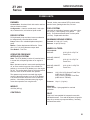
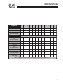
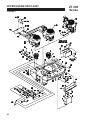
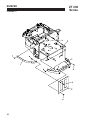
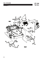
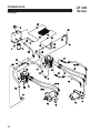
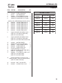
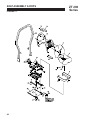
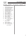
ZT219 19HP KAW W/48 SIDE DISCHARGE
942221E
ZT219 19HP KAW W/52 SIDE DISCHARGE
942233E
ZT225 25HP KAW W/61 SIDE DISCHARGE
942244E
ZT225 25HP KAW W/52 SIDE DISCHARGE
942237E
ZT227 27HP KLR W/61 SIDE DISCHARGE
942248E
Rev. A 01-2008
MAN 4163279
ZT221 21HP KAW W/52 SIDE DISCHARGE
OPERATOR’S MANUAL 4163280
942249E
ZT227 27HP KAW W/61 SIDE DISCHARGE
PARTS MANUAL
942220E
CALIFORNIA
WARNING
Proposition 65 Warning
Diesel engine exhaust and some
of its constituents are known to the
State of California to cause cancer,
birth defects and other reproductive
harm.
The engine exhaust from this product
contains chemicals known to the State
of California to cause cancer, birth
defects or other reproductive harm.
Californie Proposition 65 Avertissement
Avertissement
Les échappements des moteurs diesel
et certains de leurs composés sont
reconnus par l’Etat de Californie pour
être cancérigènes, provoquer des défauts congénitaux et d’autres dangers
en matière de reproduction.
California Advertencia
L’émission du moteur de ce matériel
contient des produits chimiques que
l’Etat de Californie considère être
cancérigènes, provoquer des défauts
congénitaux et d’autres dangers en
matière de reproduction.
de la Proposicion 65
El estado de California hace saber
que los gases de escape de los motores diesel y algunos de sus componentes producen cáncer, defectos
de nacimiento y otros daños en el
proceso de reproducción humana.
Advertencia
El estado de California hace saber
que los gases de escape de este
producto contienen productos quÍmicos que producen cáncer, defectos
de nacimiento y otros daños en el
proceso de reproducción humana.
CALIFORNIA
Proposition 65 Warning
Battery posts, terminals, wiring
insulation, and related accessories
contain lead and lead compounds,
chemicals known to the State of
California to cause cancer and birth
defects or other reproductive harm.
WASH HANDS AFTER HANDLING.
ZT 200
Series
IMPORTANT MESSAGE
Thank you for purchasing this CGC, Inc. product. You have purchased a world class mowing product, one of
the best designed and built anywhere.
This machine comes with an Operation and Safety Manual and a separate Setup, Parts and Maintenance Manual.
The useful life and good service you receive from this machine depends to a large extent on how well you read
and understand these manuals. Treat your machine properly, lubricate and adjust it as instructed, and it will give
you many years of reliable service.
Your safe use of this CGC, Inc. product is one of our prime design objectives. Many safety features are built in,
but we also rely on your good sense and care to achieve accident-free operation. For best protection, study the
manuals thoroughly. Learn the proper operation of all controls. Observe all safety precautions. Follow all instructions and warnings completely. Do not remove or defeat any safety features. Make sure those who operate this
machine are as well informed and careful in its use as you are.
See a CGC, Inc. dealer for any service or parts needed. CGC, Inc. service ensures that you continue to receive
the best results possible from CGC, Inc. products. You can trust CGC, Inc. replacement parts because they are
manufactured with the same high precision and quality as the original parts.
CGC, Inc. designs and builds its equipment to serve many years in a safe and productive manner. For longest
life, use this machine only as directed in the manuals, keep it in good repair and follow safety warnings and
instructions. You’ll always be glad you did.
Commercial Grounds Care, Inc.
One Bob Cat Lane
Johnson Creek, WI 53038-0469
TABLE OF CONTENTS
FIGURES
PAGE
SAFETY................................................................................................................................................................................ 2
ASSEMBLY AND SETUP.................................................................................................................................................. 3-5
MAINTENANCE CHART ..................................................................................................................................................... 6
MAINTENANCE RECORD................................................................................................................................................... 7
MAINTENANCE ............................................................................................................................................................. 8-14
ADJUSTMENTS............................................................................................................................................................ 15-18
BELT REPLACEMENT ................................................................................................................................................ 19, 20
SPECIFICATIONS......................................................................................................................................................... 21-24
PARTS SECTION............................................................................................................................................................... 25
UPPER ENGINE DECK ASSY...................................... FIGURE 1............................................................................... 26, 27
LOWER ENGINE DECK ASSY/CLUTCH..................... FIGURE 2............................................................................... 28, 29
BUMPER.......................................................................FIGURE 3............................................................................... 30, 31
FUEL TANKS/CONTROL PANEL.................................. FIGURE 4............................................................................... 32, 33
BRAKES/REAR WHEEL...............................................FIGURE 5............................................................................... 34, 35
OIL COOLER.................................................................FIGURE 6............................................................................... 36, 37
HYDRAULICS...............................................................FIGURE 7............................................................................... 38, 39
HYDROGEAR PUMP....................................................FIGURE 8............................................................................... 40, 41
KOHLER WIRE HARNESS...........................................FIGURE 9............................................................................... 42, 43
KAWASAKI WIRE HARNESS.......................................FIGURE 10............................................................................. 44, 45
SEAT ASSEMBLY & ROPS...........................................FIGURE 11............................................................................. 46, 47
FOLDING ROPS KIT.....................................................FIGURE 12............................................................................. 48, 49
STEERING/DECK LIFT.................................................FIGURE 13............................................................................. 50, 51
CRADLE ASSEMBLY....................................................FIGURE 14............................................................................. 52, 53
CRADLE & CASTER ASSEMBLY................................. FIGURE 15............................................................................. 54, 55
48” SIDE DISCHARGE.................................................FIGURE 16............................................................................. 56, 57
52” SIDE DISCHARGE.................................................FIGURE 17............................................................................. 58, 59
61” SIDE DISCHARGE.................................................FIGURE 18............................................................................. 60, 61
BELTS-CUTTERDECK..................................................FIGURE 19............................................................................. 62, 63
DECALS-POWER UNIT................................................FIGURE 20............................................................................. 64, 65
DECALS-CUTTERDECKS............................................FIGURE 21............................................................................. 66, 67
01-2008
1
SAFETY
ZT 200
Series
NOTICE !!!
Unauthorized modifications may present extreme
safety hazards to operators and bystanders and
could also result in product damage.
Commercial Grounds Care, Inc. strongly warns
against, rejects and disclaims any modifications,
add-on accessories or product alterations that are
not designed, developed, tested and approved by
CGC, Inc. Engineering Department. Any CGC, Inc.
product that is altered, modified or changed in any
manner not specifically authorized after original
manufacture-including the addition of “after-market”
accessories or component parts not specifically
approved by CGC, Inc.-will result in the CGC, Inc.
Warranty being voided.
Any and all liability for personal injury and/or property
damage caused by any unauthorized modifications,
add-on accessories or products not approved by
CGC, Inc. will be considered the responsibility
of the individual(s) or company designing and/or
making such changes. CGC, Inc. will vigorously
pursue full indemnification and costs from any party
responsible for such unauthorized post-manufacture
modifications and/or accessories should personal
injury and/or property damage result.
This symbol means:
ATTENTION!
BECOME ALERT!
Your safety and the safety of others is involved.
Signal word definitions:
The signal words below are used to identify levels
of hazard seriousness. These words appear in
this manual and on the safety labels attached
to CGC, Inc. machines. For your safety and the
safety of others, read and follow the information
given with these signal words and/or the symbol
shown above.
DANGER indicates an imminently hazardous
situation which, if not avoided, will result in death
or serious injury.
WARNING indicates a potentially hazardous
situation which, if not avoided, could result in
death or serious injury.
CAUTION indicates a potentially hazardous situation
which, if not avoided, may result in minor or moderate
injury. It may also be used to alert against unsafe
practices or property damage.
CAUTION used without the safety alert symbol
indicates a potentially hazardous situation which, if
not avoided, may result in property damage
MODEL NUMBER: This number appears on
sales literature, technical manuals and price lists.
SERIAL NUMBER: This number appears only
on your mower. It contains the model number
followed consecutively by the serial number.
Use this number when ordering parts or seeking
warranty information.
2
ZT 200
Series
ASSEMBLY AND SETUP
Tools required for assembly
-
-
-
-
-
-
-
-
Wrecking bar
Claw hammer
Ratchets: 3/8”
Sockets: 3/8”, 1/2”, 17 mm
Wrenches: 13 mm, 15 mm, 17 mm, 18 mm, 1-1/16”, 1-1/8”
Straight edge
Tire pressure gauge
Blocks (for deck leveling)
NOTE: All references below to the “right” or “left” are with respect to an operator at the controls.
1. UNCRATE UNIT
a) Discard packing materials. Remove and discard shipping brackets. Tighten caster wheel axle bolts
against caster axle spanner bushings.
2. INSTALL SEAT
a) Install bushings J in seat plate Z.
b) Install seat assembly onto the unit using (2) pins X and (2) E-clips Y.
c) Secure seat wire W on the bottom of the seat plate with clip C and a 1/4-20 X 3/8” thread forming screw.
d) Connect the tractor harness to the seat wire.
Bottom of seat plate Z showing clip C
3. Set tire pressures to 14 lbs/in2 (1.0 kg/cm2). Tires are overinflated for shipping.
3
ASSEMBLY AND SETUP
4. TRACTION LEVERS
a) Loosen bolt A and remove bolt B.
b) Rotate traction lever D into position and secure
with bolts A and B. Repeat for the other lever.
c) Tighten all fasteners.
d) Sit on the machine. Levers may be adjusted
in bracket C for a more comfortable reach, or
moved to upper set of holes for a better operator
fit.
5. DECK LEVELING
a) Park the machine on a smooth, level surface.
Raise the deck to the transport position.
b) Lower the deck onto a set of equal height blocks
A under the rear corners of the deck. Place another set of blocks B under the front of the deck
so that the deck top is pitched forward 1/8”.
NOTE: The front and rear of the deck are at different
heights.
c) Measure the height of the blade cutting edge
above the ground. Remove pin C and set the
height of cut lever D to that height.
d) Loosen nuts I at all four corners of the deck.
NOTE: This will relieve tension on chains H.
e) Loosen the jam nuts E on the height of cut clips
F and adjusting screws G. Turn the adjusting
screws G until the play is taken out of the chains
H at all four corners. Tighten the jam nuts E
against the clips F and at the adjusting screws G.
Retighten nuts I at this time.
4
ZT 200
Series
ASSEMBLY AND SETUP
ZT 200
Series
6. COUNTERBALANCE SPRINGS
a) Raise the cutterdeck all the way.
b) Adjust the spring A with nut B:
52” cutterdecks to a length of 9-1/8” (232 mm)
61” cutterdecks to a length of 9-9/16” (242 mm)
The springs may be tightened or loosened from
this point according to personal preference.
NOTE: The 48” cutterdecks do not have
counterbalance springs.
7. FINAL PREPARATIONS
-
Check the engine and hydraulic oil levels. Top up with the correct oil if necessary. Use 10W30 motor oil
for the engine. Use fresh, clean 15W40 or 20W50 motor oil or 15W50 synthetic motor oil for the hydraulic
system.
-
Remove the battery from the machine. Fill the battery to the bottom of the vent wells with acid and trickle
charge for several hours.
Battery acid is caustic and fumes are explosive and can cause serious injury or death.
Use insulated tools, wear protective glasses or goggles and protective clothing when working with batteries.
Read and obey the battery manufacturer’s instructions.
Be certain the ignition switch is OFF and the key has been removed before servicing the battery.
a) Verify battery polarity before connecting or disconnecting the battery cables.
b) When installing the battery, always assemble the RED, positive ( + ) battery cable first and the
ground, BLACK, negative ( - ) cable last.
c) Tighten cables securely to battery terminals and apply a light coat of silicone dielectric grease to terminals and cable ends to prevent corrosion. Keep terminal covers in place.
-
Read Operation and Safety Manual before starting.
-
Run engine at full RPM for 5 minutes before engaging blades to allow the engine to be fully lubricated
before load is applied.
-
Check the hydrostat neutral adjustment. Neutral is set at the factory but may require readjustment if
air trapped during the initial oil fill has worked out of the system. See adjustments section later in this
manual.
-
Do not use the machine without an approved grass collector, the grass discharge chute or mulching
plates correctly fitted.
5
MAINTENANCE CHART
MAINTENANCE
OPERATION
ZT 200
Series
Maintenance is an ongoing job. These intervals are maximum times betw een
maintenance operations. Perform more often under severe conditions.
FIRST 5
HOURS
DAILY
EVERY
25
HOURS
EVERY
50
HOURS
EVERY
100
HOURS
EVERY
200
HOURS
EVERY
50 0
HOURS
ENGINE
Consult the engine manual for additional information and instructions
Check/Top Off
Engine Coolant
L evel
(Where Applicable)
Check/Top Off
Oil Level
X
X
C h ec k F o r L e a ks
X
Clean Air Intake
Screen
X
Clean Air Cleaner
Precleaner
X*
Clean Air Cleaner
Element
X
Clean Cooling Fins
X
Change Oil And
Filter
X* *
See engine manufacturer's manual
X
Check/Replace
X
Spark Plugs
* N/A IF EQUIPPED WITH HEAVY DUTY CYCLONIC AIR CLEANER
**IF EQUIPPED WITH HEAVY DUTY CYCLONIC AIR CLEANER
HYDRAULICS
C h ec k F o r L e a ks
Check/Top Off
Oil Level
Change Oil And
Filter
X
X
X
X
MACHINE
Check Interlock
Operation
X
Check Tire
Pressures
X
Check/Top Off
Battery
Lubricate All Points
6
X
X
MAINTENANCE RECORD
ZT 200
Series
NOTES
________________________________________________
________________________________________________
________________________________________________
________________________________________________
________________________________________________
________________________________________________
________________________________________________
________________________________________________
________________________________________________
________________________________________________
________________________________________________
GENERAL
DATE
HRS
DATE
HRS
DATE
HRS
DATE
HRS
DATE
HRS
DATE
HRS
Check Tire Pressures
Lubricate All Points
Check Nuts & Bolts
ENGINE
Check Engine Coolant
L evel
(Where Applicable)
Check Oil Level
Change Oil
Clean
Air Cleaner Element
Clean Cooling Fins
Replace
Air Cleaner Element
Clean & Gap
Spark Plugs
NOTE: After first 5 hours of operation replace engine oil, hydraulic oil and both filters.
7
MAINTENANCE
ZT 200
Series
CHECK DAILY
Operator Presence Interlock System - Start Operation
For the engine to crank, the parking brake must be on, the PTO (blades) off and traction levers in the neutral
lock position. Sit in the seat and check, one by one, if the engine will crank with the parking brake off, the
blades on, and either traction lever out of neutral lock. Also, make sure engine coolant temperature gauge
light flashes upon turning key to the ON position.
Operator Presence Interlock System - Run Operation
The operator must be in the seat for the engine to run with the parking brake off, the traction levers moved out
of the neutral lock position, or the blades on. To check:
1. Start the engine and run at 1/2 throttle with the operator on the machine but raised off the seat.
2. One by one: move the parking brake to the OFF position, traction levers out of the neutral lock position
(check each independently), and turn the blades on. Each check should kill the engine after 1/2 second.
(A 1/2 second delay is built into the system to prevent engine cutout when traversing rough terrain.)
Repair machine before using if the Operator Presence Interlock System does not operate correctly in start or
run. Contact your authorized CGC, Inc. dealer.
Hardware
Tighten any nuts and bolts found loose. Replace any broken or missing cotter pins. Repair any other
problems before operating.
Tire pressure
Tires should be kept inflated at 14 lbs/in2 (1.0 kg/cm2). Improper tire inflation can cause rapid tire wear and
poor traction. Uneven inflation can cause uneven cutting.
BATTERY
Battery acid is caustic and fumes
are explosive and can cause serious injury or death.
4. Check the electrolyte level every 100 hours of
operation.
Use insulated tools, wear protective glasses or
goggles and protective clothing when working with
batteries. Read and obey the battery manufacturer’s
instructions.
5. Clean the cable ends and battery posts with steel
wool. Use a solution of baking soda and water
to clean the battery. Do not allow the solution to
enter into the battery cells.
Be certain the ignition switch is OFF and the key has
been removed before servicing the battery.
1. Verify battery polarity before connecting or disconnecting the battery cables.
2. When installing the battery, always assemble
the RED, positive ( + ) battery cable first and the
ground, BLACK, negative ( - ) cable last.
3. When removing the battery, always remove the
ground, negative ( - ) cable first and the red, positive ( + ) cable last.
8
6. Tighten cables securely to battery terminals and
apply a light coat of silicone dielectric grease to
terminals and cable ends to prevent corrosion.
Keep terminal covers in place.
MAINTENANCE
ZT 200
Series
LUBRICATION
Every 50 hours of operation, lubricate the following points (1-4) with grease:
1. Deck lift rockshaft (1 point)
2. Deck lift pivots (6 points)
3. Brake lever pivot (1 point)
4. Push arms (2 points located at rear of cutterdeck under each fuel tank)
5. Caster wheel pivots (2 points)
(Lubricate every 500 hours or once a year)
NOTE ON BLADE SPINDLES - The blade spindles on these machines use a
superior sealed bearing that does not require relubrication.
9
MAINTENANCE
ZT 200
Series
HYDRAULIC SYSTEM
Fluid level in the hydraulic system should be checked
after the first 5 hours of operation, and every 100
hours thereafter, or when a leak has occurred. If the
fluid is low, check all components for leaks.
To check, remove reservoir cap M. The fluid level
should be at the bottom of the filler tube. If low, top
up (do not overfill). Use one of the oils listed below:
-
-
-
SAE 15W40 motor oil
SAE 20W50 motor oil
15W50 synthetic motor oil
AFTER FIRST FIVE (5) HOURS
1. Remove plug N to drain hydraulic reservoir. Dispose of used oil in accordance with local requirements.
2. Clean and replace the plug.
3. Change hydraulic oil filter G.
4. Fill the reservoir with fresh oil to the bottom of
the reservoir filler tube, using an oil from the list
above. Do not overfill.
View from right side
PERIODIC OIL CHANGES
Change the hydraulic fluid and hydraulic filter
after each 500 hours of operation using the same
procedure given above.
View from below machine
NOTES:
Before servicing the hydraulic system, stop the engine, disconnect spark plug wires and disengage the PTO.
-
-
-
After any hydraulic line is opened, plug or cap it promptly to reduce the risk of contamination.
Do not use sealant tape on hydraulic pipe fittings. Use a liquid sealant that will dissolve into the system.
Make sure all hydraulic connections are tight and hydraulic hoses and lines are in good condition before
applying pressure to system.
The machine’s hydraulic system operates under high pressure. When checking for leaks, do not use your
hands to attempt to find a leak. Instead, use cardboard or paper. Escaping hydraulic fluid can be under sufficient pressure to penetrate skin and cause serious injury. If hydraulic fluid is injected into the skin, it must be
promptly removed by a doctor familiar with this form of injury or gangrene may result.
10
ZT 200
Series
MAINTENANCE
ENGINE OIL
Do not perform engine maintenance without the
engine off, spark plug wires disconnected and PTO
disengaged.
AFTER FIRST FIVE (5) HOURS
While the engine is warm:
1. Remove drain cap D and drain the crankcase.
Dispose of used oil in accordance with local
requirements.
2. Clean and replace the cap.
3. Change oil filter.
4. Fill the crankcase with fresh oil to the full mark.
Do not overfill. See engine manual for oil
specifications.
DAILY
1. Check oil level with the dipstick.
2. If oil is needed, add fresh oil of proper
viscosity and grade. See engine manual for oil
specifications. Do not overfill.
3. Replace dipstick before starting engine.
PERIODIC OIL CHANGES
1. See engine manual for oil and filter change intervals after the break-in period.
2. Follow instructions for first oil change, above.
Spark Plugs
Remove each plug and check condition.
-
Good operating conditions are indicated if the plug has a light coating of grey or tan deposit.
-
A white blistered coating indicates overheating. A black coating indicates an “over rich” fuel mixture. Both
may be caused by a clogged air cleaner or improper carburetor adjustment.
-
Do not sandblast, wire brush or otherwise attempt to repair a plug in poor condition. Best results are
obtained with a new plug.
-
Set plug gap as specified in engine manual.
FUEL FILTER (Carbureted MODELS)
An inline fuel filter is located in the fuel supply line. Inspect at every oil change to make sure it is clean and
unobstructed. Replace if dirty.
11
MAINTENANCE
DUAL ELEMENT AIR CLEANER
Engines equipped with dual element air cleaners
have a paper air cleaner element with an oiled, foam
precleaner element on the dirty side of the paper
element. Both should be inspected regularly and
maintained.
Clean and re-oil precleaner element every 25 hours
(more often under dusty conditions).
1. Disassemble air cleaner cover.
2. Remove precleaner by sliding it off the paper cartridge.
3. Wash precleaner in kerosene or liquid detergent
and water.
4. Wrap precleaner in cloth and squeeze to remove
cleaner.
5. Saturate precleaner in engine oil. Squeeze to
remove excess oil.
6. Re-install precleaner over paper cartridge.
Reassemble air cleaner components and screw
assembly down tight.
Every 100 hours (more often under very dusty or
dirty conditions), check the paper cartridge.
-
-
-
Clean by tapping gently.
Do not wash the cartridge or use compressed air
which can cause damage.
Replace when cartridge is dirty, bent or
damaged.
HEAVY DUTY CYCLONIC AIR CLEANER
Clean and replace the air cleaner element as
specified in the service chart. Uneven running, lack
of power or black exhaust fumes may indicate a dirty
air cleaner.
To replace air cleaner elements:
1. Unclamp end cover X and remove existing
cleaner elements.
2. Insert new elements Y and Z and replace cover.
Ensure the breathing port A is pointing down and
towards the front of the tractor.
12
ZT 200
Series
ZT 200
Series
MAINTENANCE
ENGINE COOLING
Continued operation with a clogged cooling system
will cause severe overheating and can result in engine damage.
-
Daily: Clean air intake screen S.
-
Every 100 hours: Clean cooling fins beneath
blower housing H with reference to information in
the engine manufacturer’s manual.
13
MAINTENANCE
ZT 200
Series
BLADE REMOVAL
BLADE Balance
Follow these instructions to prevent injury during
blade removal:
1. Loosen with a box wrench or a socket and long
breaker bar. To gain additional leverage, slip a
long pipe or thick-walled tube over breaker bar or
wrench.
2. Insert wood block A as shown, with grain
perpendicular to blade, to prevent blade from
turning when loosening.
3. Wear thickly padded gloves. Keep hands clear
of blade path. Blades may rotate when bolt
releases.
Blade balance must be maintained at 5/8 oz-in
(19.4 g-cm) or less. Failure to keep blades balanced
causes excess vibration, wear, and shortened life of
most components of the machine.
To balance a blade:
1. Sharpen blade first.
2. Balance the blade at the center.
3. Attach a 1/8 oz (3.9 g) weight at a distance 5”
(127 mm) from center on the light end. This
should make the light end the heavy end:
- If it does, the blade is balanced.
- If does not, file or grind the heavy end until
the addition of the weight makes the light end
the heavy end.
Blade installation
1. Wear thickly padded gloves to prevent cuts from
the sharp blade.
2. Insert the blade bolt, in order, through the conical
washer (cup side toward the blade, as shown),
the blade, and the blade spacer.
3. Install assembly on the blade spindle.
4. Torque the blade bolt to 70 ft-lbs.
Sharpening
Blades may be sharpened by filing or grinding.
- Inspect blades before sharpening.
- Replace bent or cracked blades.
- Replace blades when the lift portion has worn
thin.
o
- Maintain cut angle at 30 .
- Do not overheat blades when sharpening.
- Always use CGC, Inc. blades. Use of another
manufacturer’s blades may be dangerous.
14
ZT 200
Series
ADJUSTMENTS
deck leveling
a) Park the machine on a smooth, level surface.
Raise the deck to the transport position.
b) Lower the deck onto a set of equal height blocks
A under the rear corners of the deck. Place another set of blocks B under the front of the deck
so that the deck top is pitched forward 1/8”.
NOTE: The front and rear of the deck are at different
heights.
c) Measure the height of the blade cutting edge
above the ground. Remove pin C and set the
height of cut lever D to that height.
d) Loosen nuts I at all four corners of the deck.
NOTE: This will relieve tension on chains H.
e) Loosen the jam nuts E on the height of cut clips
F and adjusting screws G. Turn the adjusting
screws G until the play is taken out of the chains
H at all four corners. Tighten the jam nuts E
against the clips F and at the adjusting screws G.
Retighten nuts I at this time.
counterbalance springs
a) Raise the cutterdeck all the way.
b) Adjust the spring A with nut B:
52” cutterdecks to a length of 9-1/8” (232 mm)
61” cutterdecks to a length of 9-9/16” (242 mm)
The springs may be tightened or loosened from
this point according to personal preference.
NOTE: The 48” cutterdecks do not have
counterbalance springs.
15
ADJUSTMENTS
ZT 200
Series
Height of cut
The height of cut is set by moving height of cut pin N
to the hole designated for the height of cut desired.
To change the height of cut:
1. Lift the deck to the highest position.
2. Move pin N to the selected hole.
3. Lower the deck until the lift lever is stopped by
the pin.
NOTES:
-
Height of cut may vary due to the amount of
tread on the tires, tire diameter or inflation pressure.
-
For best results, adjust the rear deck rollers for
the height of cut to be used (see below).
REAR DECK RollerS
The rear outside deck rollers are adjustable up and
down to provide improved deck flotation and scalping protection at various heights of cut. They are not
intended to ride continuously on the ground. Adjust
no closer than 3/8” (10mm) to the ground.
Height of cut ranges for roller adjustment
Belts
All belts are tensioned by spring loaded idlers. No adjustment is required.
16
ZT 200
Series
ADJUSTMENTS
CONTROL LEVERS
There are two mounting positions for the control
levers, upper and lower. The lower position works
well for most people. Taller operators may need the
upper position.
To adjust the height of the control levers:
-
-
-
Remove bolts A and nuts B.
Align holes in control lever D with appropriate
holes in traction lever bracket C.
Install bolts A and nuts B.
The upper mounting hole for the control levers is
slotted to allow fore-aft adjustment and to allow
alignment of the levers.
To adjust or align the control levers:
- Loosen nuts B.
- Adjust control lever position.
- Tighten nuts B.
Parking Brake
Park machine on a smooth level surface.
Support the machine with the rear wheels off the
ground, using jack stands or equivalent. DO NOT
rely on mechanical or hydraulic jacks.
1. Remove rear wheels.
2. Measure spring length O with parking brake N in
the OFF position.
3. Move parking brake N to the ON position and
measure length of spring O again. When spring
deflects 3/8” it is properly adjusted.
4. If adjustment is required, return parking brake N
to the OFF position.
5. Disconnect one end of rod M at the brake and
loosen jam nut.
6. Adjust rod M in or out as required until 3/8” deflection in brake spring O is achieved with parking brake N in the ON position.
7. Reconnect rod M and retighten jam nut.
8. Repeat steps 2-7 on opposite side of machine.
9. Replace wheels and tighten wheel nuts.
NOTE: Parking brake must be in the OFF position to
properly seat brake drums.
Parking brake assembly (tire and deck not shown
for clarity - brake in ON position).
This adjustment will cause the brake springs to
stretch 3/8” when the parking brake is in the ON position, providing the correct parking brake force without
overloading the brake arm.
17
ADJUSTMENTS
ZT 200
Series
Hydrostat adjustmentS
A turnbuckle-style hydrostat neutral adjustment is
provided.
Neutral:
1. Support the machine with the rear wheels off
the ground. Use jackstands or equivalent support. Do not rely only on mechanical or hydraulic
jacks.
2. Move the traction levers out into the neutral lock
position and raise the seat.
3. Disconnect the seat switch wire K and
temporarily connect the two terminals with
jumper wire J as shown.
4. Start the engine and run at low speed.
5. Loosen jam nuts T at both ends of the
turnbuckle.
6. Rotate the turnbuckle until the corresponding
wheel stops turning. Lock the turnbuckle jam
nuts. Run the engine up to high idle to check the
adjustment. Readjust if necessary.
7. Repeat steps 5 and 6 for the opposite side.
8. Remove the jumper wire and reconnect the seat
switch.
Reverse Return:
1. Move traction levers out to the neutral lock position and raise the seat.
2. Locknut U should be run on the bolt as far as it
will go.
3. Loosen jam nut Y. Adjust the clevis yoke by
turning the head of the bolt until the clevis pin
just makes contact with the rear of the slot in the
lever it connects with. Tighten jam nut Y.
4. Repeat steps 2 and 3 for the opposite side.
NOTE: A slight creep in reverse is acceptable
provided the wheel does not turn and the hydrostat
pump does not whine when the parking brake is on.
Right side adjustments
(wiring harness and seat rod removed for clarity)
18
ZT 200
Series
BELT REPLACEMENT
Note: Always use CGC, Inc. replacement belts, not general purpose belts. CGC, Inc.
belts are specially designed for use on commercial mowers and will normally last longer.
Engine-Cutterdeck (PTO) belt
1. Set the cutterdeck in the lowest height-of-cut
position.
2. Attach a short extension to a 3/8” drive ratchet.
Insert the ratchet extension into the square hole
in the idler arm and use the ratchet to rotate
the idler assembly enough to remove the belt.
Remove the belt from the idlers and center cutterdeck pulley. Push belt back under engine
deck.
3. Disconnect the electric clutch from the wire harness at plug P.
4. Remove the carriage bolts securing torque restraint Q to clutch R. Remove torque restraint.
5. Remove old belt from the machine.
6. Install a new belt by performing the these steps
in reverse order.
19
BELT REPLACEMENT
ZT 200
Series
Cutterdeck belt
1. Set the cutterdeck in the lowest height-of-cut
position.
2. Remove the engine-cutterdeck belt from the deck
idlers and pulley (see engine-cutterdeck belt
replacement). Push it aside but don’t remove it
from the machine.
3. Run the cutterdeck belt off the idler as shown.
Remove it from the deck.
4. Install the new belt by performing these steps in
reverse order. Take care to get the new belt on
the correct side of the belt guides.
5. Re-install engine-cutterdeck belt (see enginecutterdeck belt replacement).
Pump-drive belt
1. Remove engine-cutterdeck belt (see engine-cutterdeck belt replacement).
2. Attach an extension to a 3/8” drive ratchet. Insert the ratchet extension in the square hole of the pump
drive idler arm. Use the ratchet handle to rotate it enough to remove the pump drive belt.
3. Install a new pump drive belt in the same manner as it was removed.
4. Re-install engine-cutterdeck belt (see engine-cutterdeck belt replacement).
20
SPECIFICATIONS
ZT 200
Series
POWER UNITS
ENGINES:
Throttle; choke; power takeoff (PTO) clutch switch;
traction levers; parking brake lever; lift lever.
Configuration: 4-stroke, vertical shaft, V-twin cylinder, overhead valve, air-cooled or liquid cooled.
FUEL SYSTEM:
Construction: Aluminum block with cast-in cast iron
sleeves. Aluminum head.
DRIVE SYSTEM:
Full hydrostatic pump and wheel motor combination
for independently controlled drive wheels.
Pump: Parker 12cc variable displacement piston
pump.
Motors: Parker displacement MB series. Direct
drive 1-1/4” (31.8mm) diameter output shaft.
Turn Radius: True Zero
OPERATOR PRESENCE
INTERLOCK SYSTEM:
Start: The PTO (blades) must be off, traction levers
in neutral lock, and parking brake on for engine to
crank.
Run: Operator must be in seat to take parking brake
off, to move traction levers out of the neutral lock
position, or to turn the PTO (blades) on or the engine
will kill. The parking brake must be off for the traction
levers to move out of the neutral lock position.
The operator may leave the seat with the engine
running if the parking brake is on, the PTO (blades)
is off, and the traction levers are in the neutral lock
position. A time delay eliminates annoying engine
cutout from operation over rough terrain.
WEIGHT:
1025 lbs (465 kg)
CONTROLS:
One tank on each side of operator, each with a shutoff (1/4 turn). Total capacity 9-1/2 gallons
(40
liters). Fuel selector/shutoff switch on front panel
(1/4 turn). Replaceable fuel filter.
MAXIMUM GROUND SPEEDS:
Forward: 8.5 mph (13.7 km/h)
Reverse: 4 mph (6.4 km/h)
WHEELS & TIRES:
Drive wheels:
942220E:
23 X 8.50-12 4-Ply Turf Tread Tires
942244E, 942221E,
942248E:
23 X 10.5-12 4-Ply Turf Tread Tires
942233E, 942237E:
942249E
24 X 12.00-12 4-Ply Turf Tread Tires
Casters:
13 X 5.00-6 4-Ply Smooth Tread Tires
(USED ON 52” DECKS)
13 X 6.5-6 4-Ply Smooth Tread Tires
(USED ON 61” DECKS)
Pressure: 14 p.s.i. (1 kg/cm2)
BRAKING:
Parker brakes. Spring applied for overload
protection.
SEAT:
High back, foam padded full suspension seat with
standard armrests. Fore and aft adjusters, hinged for
easy tilt-up access to pumps and battery. Internally
mounted seat switch.
21
SPECIFICATIONS
ZT 200
Series
ENGINES
22
MODEL
NUMBERS
942220E,
942221E
942233E,
942244E
942237E
942248E
942249E
MANUFACTURER
Kawasaki
Kawasaki
Kohler
Kawasaki
Kawasaki
MODEL
FHV19
FHV25
CV740
FHV21
FX751
CYLINDERS
2
2
2
2
2
COOLING
Air
Air
Air
Air
Air
BORE/STROKE
2.96 X 2.99"
(75.2 X 76 mm)
2.96 X 2.99"
(75.2 X 76 mm)
3.27 X 2.64"
(83 X 67mm)
2.96 X 2.99"
(75.2 X 76 mm)
3.33 X 2.99"
(184.5 76mm)
DISPLACEMENT
41.2 cu.in.
(675 cc)
41.2 cu.in.
(675 cc)
44 cu. in.
(725cc)
41.2 cu. in.
(675cc)
52.0 cu. in.
(852cc)
COMPRESSION
8.5:1
8.1:1
9:1
8.5:1
8.2:1
OUTPUT POWER
19 hp (14.2 kw)
@ 3600 rpm
25 hp (18.6 kw)
@ 3600 rpm
27hp (20.1kw)
@ 3600 rpm
21hp (15.6.1kw)
@ 3600 rpm
27hp (20.1 kw)
@ 3600 rpm
OUTPUT TORQUE
37.0 ft-lb (50.2
J)
@ 2500 rpm
41.3 ft-lb (56.0
J)
@ 2400 rpm
42.7 ft-lb (57.9
J)
@3000 rpm
LUBRICATION
FULL
PRESSURE
FULL
PRESSURE
FULL
PRESSURE
FULL
PRESSURE
FULL
PRESSURE
GOVERNOR
Mechanical
Mechanical
Mechanical
Mechanical
Mechanical
AIR CLEANER
Dual element
Heavy duty
cyclonic
Heavy duty
cyclonic
Dual element
Dual element
IGNITION SYSTEM
Electronic
Electronic
Electronic
Electronic
Electronic
CHARGING
SYSTEM
15 amp,
regulated
15 amp,
regulated
15 amp,
regulated
15 amp,
regulated
15 amp,
regulated
BATTERY
BCI group U1
BCI group U1
BCI group U1
BCI group U1
BCI group U1
FUSES
Two, 20 amp
blade
Two, 20 amp
blade
Two, 20 amp
blade
Two, 20 amp
blade
Two, 20 amp
blade
FUEL
CONSUMPTION
@ MAX LOAD/
SPEED
1.7 gal./hr
(6.5 l/hr)
2.3 gal./hr
(8.8 l/hr)
2.2 gal./hr
(8.3 l/hr)
SPECIFICATIONS
ZT 200
Series
GENERAL
DATE
HRS
DATE
HRS
DATE
HRS
DATE
HRS
DATE
HRS
D ATE
HRS
Check Tire Pressures
Lubricate All Points
Check Nuts & Bolts
ENGINE
Check Engine C oolant
L evel
(Where Applicable)
Check Oil Level
Change Oil
Clean
Air C leaner Element
C lean C ooling Fins
Replace
Air C leaner Element
Clean & Gap
Spark Plugs
NOTE: After first 5 hours of operation replace engine oil, hydraulic oil and both filters.
23
SPECIFICATIONS
ZT 200
Series
CUTTERDECKS
MODEL NUMBER
942220E
942221E, 942244E,
942248E
942233E, 942237E
942249E
TYPE
Side Discharge
Side Discharge
Side Discharge
CUTTING WIDTH
47.25" (120 cm)
52.5" (133 cm)
61" (155 cm)
WIDTH
N/A
N/A
N/A
WIDTH
(CHUTE UP)
54" (137 cm)
56.25" (143 cm)
62" (157 cm)
WIDTH
(CHUTE DOWN)
59" (150 cm)
64.5" (164 cm)
73" (185 cm)
BLADE
high lift
(low lift optional)
high lift
(low lift optional)
high lift
(low lift optional)
NUMBER OF
BLADES
3
3
3
BLADE LENGTH
16.25" (41 cm)
18" (46 cm)
21" (53 cm)
BLADE THICKNESS
.205" (5.2 mm)
.205" (5.2 mm)
0.25" (6.35 mm)
TIP SPEED
16778 ft/min
5114 m/min
@3600 Engine RPM
18585 ft/min
5665 m/min
@ 3600 Engine RPM
18850 ft/min
5745 m/min
@ 3500 Engine RPM
DAILY PRODUCTION
(8 hr @ 6 mph)
Up to 22.9 acres
(9.3 ha)
Up to 25.5 acres
(10.3 ha)
Up to 29.5 acres
(11.9 ha)
CONSTRUCTION:
Fabricated and welded 10-gauge, double-layer steel
top with 7-gauge side skirts. Full floating design.
CUTTERDECK DRIVE SYSTEM:
Electric clutch/brake drives belt directly from engine
to center spindle of cutterdeck. No twists in drive
belt.
SPINDLES:
Top mounted and maintenance free, with 1” shaft in
precision machined, aluminum housing
SPECIFIC TORQUES
BLADE BOLT TORQUE: 70 FT-LBS (95 Nm)
WHEEL HUB NUTS: 225 FT-LBS (237 Nm)
ENGINE CRANKSHAFT BOLT: 50 FT-LBS (68 Nm)
24
ANTI-SCALP ROLLERS:
48” Cutterdecks - 3 Rollers
52” Cutterdecks - 6 Rollers
61” Cutterdecks - 7 Rollers
CUTTING HEIGHT & PRODUCTION:
Height: Spring assisted lift lever allows easy setting
of cut heights from 1-1/2” to 4-1/2” in 1/4” increments.
“Set and forget” feature allows height of cut to be
set and returned to without searching from operator
position.
NOTE: 48” cutterdecks do not use spring assisted
lift levers.
ZT 200
Series
PARTS SECTION
PARTS
SECTION
25
UPPER ENGINE DECK ASSY
FIGURE 1
26
ZT 200
Series
UPPER ENGINE DECK ASSY
ZT 200
Series
ITEM PART NO.
FIGURE 1
DESCRIPTION
QTY
ITEM PART NO.
1
4118340 ENG-KAW FHV 25 HDAC
1
4114746 S-AIR FILTER PRIMARY
1
4114747 S-AIR FILTER SAFETY
1
2722214 FILTER-OIL
1
38666
FILTER-FUEL
1
2
4137278 PUMP-HYDROSTATIC 12CC 2
(SEE FIGURE 8 FOR BREAKDOWN)
3
4136780 S-ENGINE DECK W/LABS 1
4
BATTERY
1
(OBTAIN LOCALLY)
5
4138859.7 BRACKET-RELAY MNTG
1
6
2186211 S HYD RESERVOIR W/LABS1
7
64263-013 BLT-FLG HD M10-1.5 X 30 4
8
64197-016 BLT-TDFM 3/8-16X1/2
4
9
64268-03 LOCKNUT-3/8-16
4
10
831861
BOLT,BENT BATT HOOK
2
11
64141-4 NUT-WLF 3/8-16
8
12
64237-03 LOCKNUT-NYLON M10-1.5 8
13
4118430 ARM-PUMP
2
14
38369-02 ROD END BALL JOINT LH 2
15
2188140 TURNBUCKLE
2
16
64205-003 BLT-MET M8-1.25X30
4
17
64229-02 LOCKNUT-NYLON 5/16-18 2
18
2182405.7 BRKT-REVERSE RETURN 2
19
A1104057 BOLT-M10-1.50X25
4
20
64246-03 NUT-WHIZ M10-1.50
4
21
64123-205 BLT-HEX 5/16-24X4
2
22
2188145 BEARING-.75IDSELF-ALIGN 4
23
38020N
CLEVIS YOKE, 5/16 PLATE 2
24
64188-02 PIN, CLEVIS 5/16X1
2
25
64168-2 COTTER-HAIRPIN.08X1.19 2
26
64025-03 NUT-HEX 5/16-24
4
27
2188139 SPRING-COMPRESSION
2
28
2721246 DAMPENER
2
29
4112105.7 WLDMT-MOTION CTRL RH 1
*4112104.7 WLDMT-MOTION CTRL LH 1
43
44
45
46
47
48
49
50
51
52
53
54
55
56
57
64163-55
2188146
64123-15
64152-23
38304-02
810149
69216.7
64018-23
4159840
64152-46
64025-15
64229-08
64025-33
64263-002
4118507.7
*4118508.7
58
2720607
4114746
4114747
2722214
38666
30
64237-05 LOCKNUT-NYLON M8-1.25 8
31
38369-01 ROD END BALL JOINT RH 2
32
2182427.7 HOLDDOWN-BATTERY
1
33
64192-06 SETSCR SQHD 5/16-18X3/4 2
34
112386
BOOT,BAT TERM POS
1
35
108208
SWITCH DBL POLE
2
36
2188156 SWITCH-NONO DBL POLE 1
37
64197-015 BLT-TDFM 10-32X1/2 TORX 8
38
2188154 MODULE-DELAY
1
39
11060-9016GASKET-MUFFLER
2
(AVAILABLE THROUGH KAWASAKI DEALER)
40
2308095 COVER-TERMINAL
1
41
4158086.7 PLATE-KICK
1
42
64263-011 BLT-FLG HD M10-1.5 X 20 4
64
65
66
67
59
60
61
62
63
68
69
70
DESCRIPTION
QTY
WASHER .328X.75X14 GA
STRIP, WEAR
BOLT-3/8-16X3/4 HEX
1/4-20X3/8 LG SP SCREW
BRG, FLGD PLASTIC
BUMPER-RUBBER
CAP-RESERVOIR
BLT-CRG 3/8-16X3/4
ENGINE-21HP KAW
SCREW-SLT HH 10-24X1/2
NUT-HEX #10-24 KEPS
LOCKNUT NYLON 5/16-24
NUT-HEX 5/16-24 LH
BLT-FLG HD M6-1.0 X 16
BRKT-MUFFLER LH
BRKT-MUFFLER RH
4
2
8
4
2
8
1
4
1
2
2
2
2
4
1
1
ENGINE-KAWASAKI FHV 19 1
S-AIR FILTER PRIMARY
1
S-AIR FILTER SAFETY
1
FILTER-OIL
1
FILTER-FUEL
1
(ITEMS 39, 46, 56 & 59-62 FOR USE WITH
KAWASAKI ENGINES ONLY)
64263-007 BLT-FLG HD M8-1.25 X 20 2
64266-02 NUT-FL LOCK M8-1.25
2
2188226 ASSY-MUFFLER
1
38665
SOLENOID
1
4123374 ENGINE-KOHLER CV740S 1
(SERVICE MANUAL KOHLER #TP-2475-A)
4114746 S-AIR FILTER PRIMARY
1
4114747 S-AIR FILTER SAFETY
1
842502
FILTER-OIL
1
38666
FILTER-FUEL
1
48024-17A NIPPLE-PIPE 3/8 X 5
2690033-01 ELBOW 3/8 PIPE, 90 DEG
690501
PLUG-PIPE 3/8
4163086 ENGINE, KAW FX751 *4152953 S-AIR FILTER PRIMARY
*4152954 s-AIR FILTER SAFETY
4163089 ASSY-MUFFLER
4163124.7 BRACKET MUFFLER RH
*4163123.7 BRACKET MUFFLER LH
64263-001 BLT-FLG HD M8-1.25 X 20
(ITEMS 67 - 70 USED ON 942249E ONLY)
1
1
1
1
1
1
1
4
* NOT ILLUSTRATED
27
LOWER ENGINE DECK ASSY/CLUTCH
FIGURE 2
28
ZT 200
Series
LOWER ENGINE DECK ASSY/CLUTCH
ZT 200
Series
ITEM PART NO.
FIGURE 2
DESCRIPTION
QTY
1
2
3
4
5
6
4158360 PULLEY-PUMP
2
64044-18 SCREW-SET 1/4-20 X 5/16 4
64238-03 KEY-MET 5MM SQX28MM 2
64164-12 KEY
1
4157860 PULLEY-5.25 ENGINE
1
2721337 CLUTCH-ELECTRIC
1
(USED ON ALL MODELS EXCEPT 19HP)
(INCLUDES ITEMS 29 & 30)
2722016 CLUTCH-ELECTRIC 19HP 1
(USED ON 19HP MODELS ONLY)
(INCLUDES ITEMS 29 & 30)
7
2721338.7 WLDMT-CLUTCH STOP
1
(USED ON ALL MODELS EXCEPT 19HP)
2721331.7 WLDMT-CLUTCH STOP
1
(USED ON 19HP MODELS ONLY)
8
9
10
11
12
13
14
15
2186147.7 WLDMT-CLUTCH BRACKET 1
38304-03 BEARING-FLANGED PLSTC 1
64205-001 BLT-MET M8-1.25X20
2
64197-005 BLT-TDFM 3/8-16X1-1/4
4
64006-06 LCKWSHER-HELICAL 7/16 1
64265-04 NUT-FL NYL LOCK M8-1.25 2
2308000 PULLEY-IDLER 4.00 EOD
1
4128923 S-ASSY-IDLER ARM PUMP 1
(INCLUDES ITEMS 16, 18 & 24)
16
4127999
17
64270-01
18
4128004
19
33148-01
20
2188131
21
64006-03
22
64123-21
23
4136780
24
64144-40
25
4162583
26
64123-155
27
64205-013
28
64209-09
29
2720949
30 * 4121560
31
4128002
ITEM PART NO.
DESCRIPTION
QTY
SEAL
1
BOLT-MET HEX M10-1.5X30 1
BEARING
1
SPACER-0.379X0.750X0.25 1
SPRING-EXTENSION
1
WSHR, 3/8 HELICAL LOCK 1
BLT-HEX 3/8-24X1-1/4
1
S-ENGINE DECK W/LABS 1
SNAP RING
1
BELT-TRACTION DRIVE
1
BLT-HEX 7/16-20X3
1
BLT-MET M6-1X12
2
WASHER-CONICAL SPRING2
ASSY-CLUTCH WIRE
1
KIT-BRAKE POLE RPLCMNT1
END CAP
1
* NOT ILLUSTRATED
29
BUMPER
FIGURE 3
30
ZT 200
Series
BUMPER
ZT 200
Series
ITEM PART NO.
3-1
3-2
3-3
3-4
3-5
3-6
2722296.7
4136780
2721324.7
64263-013
64265-05
2721932.7
FIGURE 3
DESCRIPTION
QTY
ARM-BUMPER
S ENG DECK W/LABS
WLDMT-BUMPER
BLT-FLG HD M10-1.5 X 30
NUT-FL NYL LOCK M10-1.5
BRACE-VERTICAL
ITEM PART NO.
DESCRIPTION
QTY
2
1
1
10
10
1
31
FUEL TANKS/CONTROL PANEL
FIGURE 4
32
ZT 200
Series
FUEL TANKS/CONTROL PANEL
ZT 200
Series
ITEM PART NO.
FIGURE 4
DESCRIPTION
QTY
1
4162990 TANK-FUEL LH (INCLUDES ITEMS 18 & 19)
1
2
4162991 TANK-FUEL RH (INCLUDES ITEMS 18 & 19)
1
3
4
5
6
7
8
9
10
11
12
13
14
15
16
17
18
19
20
21
22
23
24
25
26
27
28
29
30
31
32
33
34
4159162 S-CONTROL PANEL
1
4136780 S ENG DECK W/LABS
1
4160281 S DOC TUBE W/LABEL
1
4130320 CAP-FUEL GASOLINE 3.5 2
4110023 PLUG-SWITCH HOLE
2
64205-007 BLT MET M10-1.50X20
12
38061A
VINYL CAP
1
2188178 SWITCH-RETAINER
1
64263-001 BLT-FLG HD M6-1.0 X 12
5
88042N
HOSE CLAMP
6
128010
KEY-SWITCH
1
118020-16 CONTROL-THROTTLE 48 1
2721505 SWITCH-PTO
1
64025-15 NUT-HEX #10-24 KEPS
2
64152-46 SCR.-SLT HH #10-24X1/2
2
4132325 GROMMET-FUEL TANK
2
4162997-001TUBE-FUEL LINE
2
800488
LOCKWASHER M10
8
64251-004 WASHER-M10
8
2188161 VALVE-TANK SELECTOR
1
4162977-016HOSE,.25IDX.50OD X 48" 1
4142266 CONNECTOR, 12V RECEPT 1
4162977-009 HOSE-.25IDX.50OD X 24" 1
38666
FILTER, FUEL B&S
1
128010-01 S-KEY SWITCH NYLON NUT1
128010-03 S-COVERED KEY
1
4158086.7 PLATE-KICK
1
48228-2A CLAMP
1
64246-03 NUT-WHIZ M10-1.50
4
108009-05 CONTROL-CHOKE 55"
1
64025-04 NUT-3/8-24 HEX
1
64263-002 BLT-FLG HD M6-1.0 X 16
2
ITEM PART NO.
DESCRIPTION
QTY
33
BRAKES/REAR WHEEL
FIGURE 5
34
ZT 200
Series
BRAKES/REAR WHEEL
ZT 200
Series
ITEM PART NO.
1
2
3
4
5
6
7
8
9
9A*
9B*
9C*
9D*
10
11
12
FIGURE 5
DESCRIPTION
QTY
ITEM PART NO.
DESCRIPTION
QTY
4136780 S-ENGINE DECK W/LABS 1
4158803.7 WLDMT-BRAKE ARM LH
1
4158801.7 WLDMT-BRAKE ARM RH
1
128102
SPRING,EXTENSION
2
4159241.7 WLDMT-BRAKE LEVER
1
4159701 ROD-BRAKE CONTROL
2
2182387.7 GUIDE-SPRING
2
38020N
CLEVIS YOKE, 5/16 PLATE 2
4159281 BRAKE-PARKER
2
4159281-001 Brake-Back Plate w/ Pads 1
4159281-002Brake-Drum
1
4159281-003Brake-Screw
4
4159281-004Brake-Hub
1
64163-06 WSHR,.768/.756X1.25X14 A/R
4159000 BAR-PARKING BRAKE
1
4159280 MOTOR-PARKER
2
(INCLUDES ITEMS 32 & 33)
13
4158422 ASSY-WHEEL 24 X 12-12
2
1985085-02 TIRE 24X12.00-12NHS 4PLY2
(ITEM 34 USED ON 942233E, 942237E
& 942249E)
14
4158460 ASSY-WHEEL 23 X 8.5-12
(ITEM 14 USED ON 942220E)
2
15
16
17
18
19
20
64187-03 WHEEL NUT-1/2-20
8
64188-02 PIN, CLEVIS 5/16X1
2
64061-25 ROLL PIN-1/4X1-1/4
2
2188155 GRIP, 1/4X1X4-1/2
1
2183063-01SPACER, 32MM LONG
8
4158421 ASSY-WHEEL 23 X 10.5-12 2
(ITEM 34 USED ON 942221E, 44E & 48E)
21
22
23
24
25
26
27
28
29
30
31
32
33
34
85010N
64144-34
2188145
64123-15
64141-4
64207-07
64168-2
64025-03
64006-05
4159242
450767
64164-08
64025-31
99-B34
*NOT ILLUSTRATED
ZERK, 1/4-28 STR SLFTHRD1
SNAP RING.50
1
BEARING-.75ID SELF ALIGN2
BOLT-3/8-16X3/4 HEX
4
NUT-WLF 3/8-16
4
NUT-HEX M12-1.75
8
COTTER-HAIRPIN.08X1.19 4
NUT-HEX 5/16-24
2
LOCKWSHR-HELICAL 1/2 8
WLDMT-PRK BRAKE ROD 1
CAPSCREW 12-1.75X110
8
S-KEY FOR WHEEL MOTOR2
NUT 1-20 UNSLOTTED TRW2
WASHER
1
35
OIL COOLER
FIGURE 6
36
ZT 200
Series
OIL COOLER
ZT 200
Series
ITEM PART NO.
1
2
3
4
5
6
4136780
4139443.7
64263-002
2720891.7
2188173
2186211
FIGURE 6
DESCRIPTION
S ENGINE DECK W/LABS
BRKT-COOLER FRONT
BLT-FLG HD M6-1.0 X 16
SCREEN-OIL COOLER
COOLER-OIL
S HYD RSRVR W/LABS
QTY
ITEM PART NO.
DESCRIPTION
QTY
1
1
4
1
1
1
(69053-05 IS A SERVICEABLE LENGTH OF 55")
7A
69053-05 3/8 HIGH TEMP HOSE 26" 1
7B
69053-05 3/8 HIGH TEMP HOSE 22" 1
8
9
10
11
12
13
14
15
16
17
48228-2A CABLE-CLIP 3/4 W/INSTN 2
88042-04 CLAMP-3/4 CLIP
4
58026-01 3 WAY CONNECTOR 3/8
1
2722296.7 ARM-BUMPER
2
64237-02 LOCKNUT-NYLON M6-1.00 4
4139367.7 BRACKET-REAR COOLER 2
64265-05 NUT-FL NYL LOCK M10-1.5 9
64263-013 BLT-FLG HD M10-1.5 X 30 9
4162890.7 BRACKET-REAR COOLER 2
4162889.7 BRACKET FRONT COOLER 1
(ITEMS 16 & 17 USED ON 942249E ONLY)
37
HYDRAULICS
FIGURE 7
38
ZT 200
Series
HYDRAULICS
ZT 200
Series
ITEM PART NO.
1
2
3
4
5
6
2186211
2720396
69216.7
4160243
158058-04
108205-03
FIGURE 7
DESCRIPTION
QTY
S HYD RESERVOIR W/LAB
FILTER 25 MICRON
CAP-RESERVOIR
PLUG-HYDRAULIC TANK
FTG-90 BRB 9/16-18X.38
ELBOW-MALE 45 37-ORB
1
1
1
1
2
4
(69053-05 IS A SERVICEABLE LENGTH OF 55")
7A
69053-05 3/8 HIGH TEMP HSE 18"
1
7B
69053-05 3/8 HIGH TEMP HSE 15"
1
7C
69053-05 3/8 HIGH TEMP HSE 19"
1
7D
69053-05 3/8 HIGH TEMP HSE 12"
1
7E
69053-05 3/8 HIGH TEMP HSE 22"
1
7F
69053-05 3/8 HIGH TEMP HSE 26"
1
7G
69053-05 3/8 HIGH TEMP HSE 5"
1
8
2188157-01HOSE HYD ORB 37-22.38
(USE QTY 1 ON 19HP & 25HP KAW)
(USE QTY 2 ON 27HP KLR)
9
2188157-02HOSE HYD ORB 37-25.00
(USE QTY 1 ON 25HP & 27HP KAW)
(USE QTY 2 ON 19HP KAW & 27HP KLR)
10
11
12
13
14
15
16
17
4159280 MOTOR-PARKER
2
2690030-01FTG 9/16-18 ORB X 3/8
2
58026-01 3 WAY CONNECTOR 3/8
2
88042-04 CLAMP-HOSE 5/8
14
4137278 PUMP-HYDRO 12cc
2
2720320-02HOSE-1/2 37/45 37
1
(USE ON LH SIDE OF 27HP KAW ONLY)
2188173 OIL COOLER
1
48089-03 FTG-STRGHT 8 ORB X 8 JIC
(USE QTY 1 ON 19HP KAW)
(USE QTY 2 ON 25HP KAW)
18
19
20
2
ITEM PART NO.
DESCRIPTION
QTY
SAE PORT 'O' RING
PAR T
NUMBER
THREAD SIZE
AS-568#
158061-10
9/16-18
-906
158061-11
3/4-16
-908
158061-12
7/8-14
-910
158061-13
1-1/16-12
-912
158061-14
1-5/16-12
-916
158061-16
1-5/8-12
-920
158061-03
1-7/8-12
-924
2720320-01HOSE-1/2 37/45 37 26.25
1
(USED ON 19HP , 25HP & 27HP KAW ONLY)
(USE QTY 2ON 27HP KAW)
64123-60 BOLT, 1/4-20X2 HEX
64229-01 LOCKNUT-NYL 1/4-20
2
2
39
HYDROGEAR PUMP
FIGURE 8
40
ZT 200
Series
HYDROGEAR PUMP
ZT 200
Series
FIGURE 8
ITEM HYDROGEAR PART NO. CGC, INC. PART NO.
DESCRIPTION
1
2
3
4
5
6
7
8
10
15
18
19
20
21
22
25
29
30
31
32
34
37
38
42A
42B
44
49
56
66
100
HOUSING KIT
END CAP KIT
STRAIGHT HEADLESS PIN
FLANGE BOLT M8-1.25 X 60 HOUSING O-RING
CHARGE PUMP KIT
STD GEROTOR ASSEMBLY
O-RING
SOCKET SCREW M6-1.0 x 20
BYPASS VALVE KIT (BLANK)
PUMP SHAFT KIT
BALL BEARING 17 X 40 X 12
LIP SEAL 17 x 40 x 12
SPACER
RETAINING RING
CYLINDER BLOCK KIT
BLOCK SPRING
BLOCK THRUST WASHER
VALVE PLATE
SWASH PLATE
BALL THRUST BEARING
ARM-TRUNION
SLOT GUIDE
SHOCK VALVE KIT (.031")
SHOCK VALVE KIT (BLANK)
CHARGE RELIEF VALVE KIT
TRUNNION SEAL/RETAIN KIT
STRAIGHT THREAD PLUG
5/16 SAE PLUG
OVERHAUL SEAL KIT
70516
70517
50641
50969
51232
2513027
50273
9004101-1340
50095
2513030
70521
50315
51161
50951
50329
70331
2003014
2003017
51246
2003087
50551
2003005
2000015
70743
70741
70403
2513043
9005110-4400
9005110-3100
70525
-----
-----
-----
2721615-01
2721615-02
38345-06
38345-07
38345-08
38345-10
-----
2721615-07
-----
-----
-----
-----
38345-12
-----
-----
2721615-09
188059-11
2721615-11
188059-15
2721615-13
4121354
4121355
2721615-16
2721615-17
-----
-----
2721615-18
QTY
1
1
2
4
1
1
1
1
2
1
1
1
1
1
1
1
1
1
1
1
1
1
1
1
1
1
1
1
1
1
41
KOHLER WIRE HARNESS
FIGURE 9
42
ZT 200
Series
KOHLER WIRE HARNESS
ZT 200
Series
ITEM PART NO.
FIGURE 9
DESCRIPTION
QTY
9-1
9-2
9-3
9-4
9-5
9-6
9-7
4158085 HARNESS-WIRING MAIN
1
148082-20 FUSE-20 AMP
2
108061-13 CABLE-BATTERY 36 BLACK 1
4124009 SWITCH-SEAT, NO
1
4143068 JUMPER-SEAT SWITCH
1
4136792 METER-HOUR
1
2722227-02CABLE-BATT W/CONDUIT 1
(INCLUDES ITEMS 16 & 17)
9-8
9-9
9-10
9-11
9-12
9-13
9-14
9-15
9-16
9-17
9-18
128010
KEY-SWITCH
2722325 RELAY-40AMP SEALED
2188154 MODULE-DELAY
2721505 SWITCH-PTO
2721337 CLUTCH-ELECTRIC
(INCLUDES 2720949 WIRE ASSY)
1
3
1
1
1
2720949
108208
2188156
112386
2308095
4142266
1
2
1
1
1
1
ASSY-CLUTCH WIRE
SWITCH DBL POLE
SWITCH-NONO DBL POLE
BOOT-BAT TERM POS
COVER-TERMINAL
CONNECTOR-12V ITEM PART NO.
DESCRIPTION
QTY
43
KAWASAKI WIRE HARNESS
FIGURE 10
44
ZT 200
Series
KAWASAKI WIRE HARNESS
ZT 200
Series
ITEM PART NO.
FIGURE 10
DESCRIPTION
QTY
1
2
3
4
5
6
7
4158085 HARNESS-WIRING MAIN
1
148082-20 FUSE-20 AMP
2
108061-13 CABLE-BATTERY 36 BLACK 1
4124009 SWITCH-SEAT, NO
1
4143068 JUMPER-SEAT SWITCH
1
4136792 METER-HOUR
1
2722227-01CABLE-BATT W/CONDUIT 1
(INCLUDES ITEMS 20 & 21)
2722227-02CABLE-BATT W/CONDUIT 1
(USED ON 942249E ONLY - INCLUDES
ITEMS 20 & 21)
8
9
10
11
12
128010
KEY-SWITCH
2722325 RELAY-40AMP SEALED
2188154 MODULE-DELAY
2721505 SWITCH-PTO
2721337 CLUTCH-ELECTRIC
(USED ON 25HP & 27HP ONLY)
(INCLUDES 2720949 WIRE ASSY)
2722016 CLUTCH-ELECTRIC 19HP
(USE ON 19HP MODELS ONLY)
(INCLUDES 2720949 WIRE ASSY)
1
3
1
1
1
13
14
15
16
17
18
19
20
21
22
2720949 ASSY-CLUTCH WIRE
108208
SWITCH-DBL POLE
2188156 SWITCH-NONO DBL POLE
38665
SOLENOID
2188224 HARNESS-JUMPER
(NOT USED ON 942249E MODEL)
108061-04 CABLE-BATTERY 20 RED
2188225 WIRE-GROUND
112386
BOOT-BAT TERM POS
2308095 COVER-TERMINAL
4142266 CONNECTOR-12V 1
2
1
1
1
ITEM PART NO.
DESCRIPTION
QTY
1
1
1
1
3
1
45
SEAT ASSEMBLY & ROPS
FIGURE 11
46
ZT 200
Series
SEAT ASSEMBLY & ROPS
ZT 200
Series
ITEM PART NO.
FIGURE 11
DESCRIPTION
QTY
1
4122479 SEAT-SUSPENSION
(INCLUDES ITEMS 2-15)
1
2
3
4
5
6
7
8
9
10
11
12
13
14
15
16
17
18
19
20
21
22
23
4122479-01CUSHION-SEAT BACK
4122479-02CUSHION-SEAT BOTTOM
4122479-03SLIDE RAIL-ADJUSTER
4122479-04SLIDE RAIL-SLAVE
4122479-05SKIRT-SEAT ASSY
4122479-06CLIP-SMALL XMAS TREE
4122479-07CLIP-LARGE XMAS TREE
4122479-08ASSY-CABLE
4122479-09BACK PANEL-SEAT
4124009 SWITCH-SEAT NO
4122481 ARMREST-RH
4122480 ARMREST-LH
64123-68 BOLT-HEX 5/16-18X1
64123-54 BOLT, 5/16-18X3/4 HEX
4121386.7 PLATE-SEAT
64141-6 NUT-WLF 5/16-18
4143068 JUMPER-SEAT SWITCH
33138-09 PIN-CLEVIS
64144-30 SNAP RING
38371-01 BRG-NYLINER 3/8
48228A
CABLE CLIP-INSULATED
64152-23 SCREW 1/4-20X3/8
1
1
1
1
1
3
4
1
1
1
1
1
4
4
1
4
1
2
2
2
2
2
24
25 *
26
27
28*
ITEM PART NO.
DESCRIPTION
QTY
OPTIONAL ROPS:
970162
ATT-ROPS
(INCLUDES ITEM 22)
2208260 S-SEAT BELT
2720975-07 SPACER-NYLON 3/8"
2720975-09 SPACER-NYLON 1/4"
970363
KIT-SPRING & SADDLE
1
2
2
1
* NOT ILLUSTRATED
47
FOLDING ROPS KIT (970354)
FIGURE 12
48
ZT 200
Series
FOLDING ROPS KIT (970354)
ZT 200
Series
ITEM PART NO.
1
2
3
4
5
6
7
8
9
10
11
12
13
14
15
16
17
18
19
4162879
64123-31 64151-7
4162880
4162882
4160347
64163-19
64123-28
64006-06
64151-11
64163-31
64006-03
64123-16
64025-05
64168-1
4160343
4160344
4160348
4162878
FIGURE 12
DESCRIPTION
PIN-HITCH 1/2
BOLT-1/2-13 X 3
LOCKNUT- 1/2-13 LANYARD-NYLON SEATBELT LABEL-WARNING ROPS
WASHER-FLAT 7/16 BOLT-7/16 X 1-1/4
LOCKWASHER-7/16
LOCKNUT-7/16 WASHER-3/8
LOCKWASHER-3/8
BOLT-3/8-16 X 1-1/4
NUT-3/8-16 HEX
PIN-COTTER
BUMPER RUBBER
PLUG
WASHER-FORMED WASHER-RUBBER
QTY
ITEM PART NO.
DESCRIPTION
QTY
2
2
2
2
1
1
2
2
2
2
16
8
8
8
2
2
2
2
2
49
STEERING/DECK LIFT
ZT 200
Series
FIGURE 13
36
29
31
30
50
STEERING/DECK LIFT
ZT 200
Series
FIGURE 13
ITEM PART NO.
1
2
3
4
5
6
7
8
9
10
11
12
4136780
4136792
2188161
A1104057
4122172.7
4122173.7
2183074
4144705
2188145
64123-15
64141-4
4112105.7
*4112104.7
13
14
15
16
17
18
19
20
21
22
23
24
25
26
27
28
29
30
31
32
33
34
35
36
37
38
39
40
41
42
43
64205-011
A110406
64237-03
64263-013
64205-008
64163-43
2183073
4159920.7
64168-2
2720551.7
4162904.7
2720517.7
2720516.7
4116590.7
2720501.7
4159060
64188-53
64205-052
85010N
64221-04
64175-05
64188-36
2188143
2183071-03
64265-05
2720544
4159284
64163-65
2720742
2720743
64163-29
DESCRIPTION
QTY
S ENGINE DECK W/LABS
METER-HOUR
VALVE-TANK SELECTOR
BOLT-M10-1.50X25
LEVER-TRACTION CNTRL
BRKT-TRACTION LEVER
BRKT-HANDLE
GRIP-HANDLE
BEARING-.75ID SELF ALIGN
BOLT-3/8-16X3/4 HEX
NUT-WLF 3/8-16
WLDMT-MTN CONTRL RH
WLDMT-MTN CONTRL LH
1
1
1
3
2
2
2
2
4
8
8
1
1
BLT-MET M10-1.50X40
SCREW,M10X1.5X30 HH
LOCKNUT-NYLON M10-1.5
BLT-FLG HD M10-1.5 X 30
BLT-MET M10-1.50X55
WSHR.443/.454X1X11GA
SPACER
WLDMT-CRADLE
COTTER-HAIRPIN.08X1.19
WLDMT-DECK LIFT LEVER
WLDMT-LVR STOP LATCH
BRKT-INNER DECK LIFT
BRKT-OUTER DECK LIFT
BRACKET-LIFT LINK
HANDLE-LIFT ARM
ASSY, PIN & LANYARD
PIN-CLEVIS 1/2X1.0
BLT-MET M10-1.5X50
ZERK, 1/4-28 STR SELF TH
E-RING .875
NUT-PUSH 1/2
PIN, CLEVIS 7/16X1-1/4
GRIP
SPACER-15.88X10.32X24
NUT-FL NYL LOCK M10-1.5
SPRING-COMPRESSION
ROD-LIFT STOP
WSHR .890X1.375X18GA
LBL-ZT200 HT CUT OUTER
LBL-ZT200 HT CUT INNER
WASHER-21/64 X 1 X 11GA
2
12
20
8
1
1
2
1
4
1
1
1
1
2
1
1
1
1
1
1
1
2
1
2
4
1
1
3
1
1
2
ITEM PART NO.
DESCRIPTION
QTY
* NOT ILLUSTRATED
51
CRADLE ASSEMBLY
FIGURE 14
52
ZT 200
Series
CRADLE ASSEMBLY
ZT 200
Series
ITEM PART NO.
FIGURE 14
DESCRIPTION
QTY
1
2
3
4
5
6
7
8
4118843 LABEL-WARNING
2182356.7 BRACKET-SHAFT HANGER
2188127 CHAIN-6.35 (.250) 5 LINKS
4139065 MAT-FOOT PLATE LOWER
4129955 MAT-FOOT PLATE MIDDLE
2721861 MAT-FOOT PLATE UPPER
4157861 LABEL-PROCAT
4109780 S-FOOT PLATE (BOBCAT)
(INCLUDES ITEMS 4-7)
9
10
11
12
13
14
64163-65 WASHER-.890X1.375X18GA 8
64221-04 E-RING.875
4
4159283.7 WLDMT-DECK LIFT, FRONT 1
2722559.7 WLDMT-DECK LIFT, REAR 1
2722630 CLIP-DECK HEIGHT ADJ
4
2722719 SPRING-DECK LIFT
2
(NOT USED ON 48" DECKS)
ITEM PART NO.
DESCRIPTION
QTY
1
4
4
1
1
1
1
1
15
4159920.7 WLDMT-CRADLE
1
16
64265-05 NUT-FL NYLN LCK M10-1.5 15
17
4109960 WLDMT-DECK LIFT ROD
2
18 * 4111842.7 BRKT-SPRING ANCHOR LH 1
19
4139785 MAT-FOOT LIFT
1
20
4113682 ROD-SPRING MOUNT
2
21
64141-2 NUT-WLF 1/4-20
4
22
64141-4 NUT-WLF 3/8-16
4
(ITEMS 18, 19, 20 & 22 NOT USED ON 48" DECKS)
23
24
25
26
27
28
29
30
31
64197-020 BLT-TDFM 1/4-20X1-1/2
4
64205-007 BLT MET M10-1.50X20
2
64205-029 BLT-MET M12X1.75X40
4
64205-060 BOLT-MET M12-1.75X50
4
64263-013 BLT-FLG HD M10-1.5 X 30 15
64246-04 NUT-WHIZ M12-1.75
16
85010N
ZERK, 1/4-28 STR SLFTHRD1
85051
ZERK-1/8 PIPE
6
64237-03 LOCKNUT-NYLON M10-1.5 2
(USED ON 48" ONLY)
*NOT ILLUSTRATED
53
CRADLE & CASTER ASSEMBLY
FIGURE 15
54
ZT 200
Series
CRADLE & CASTER ASSEMBLY
ZT 200
Series
ITEM PART NO.
FIGURE 15
DESCRIPTION
QTY
1
48043-03C CUP, OUTER BEARING
2
2721306.7 WLDMT-CASTER YOKE
3
DECK/W LABS
4
64123-215 BOLT-HEX 3/4-10X7 1/2
5
2722228 WHEEL-13X5.00-6 ASSY
(INCLUDES ITEMS 6-8)
(USED ON 48" & 52" DECKS ONLY)
4
2
6
7
8
9
10
11
12
13
2720475-01TIRE-13X5.00-6 SMOOTH
2722228-03BEARING
2722228-01RIM-13"ASSY W/VALVE
2722231 SPACER-END
64163-26 WASHER
64229-07 LOCKNUT-NYLON 3/4-10
85010N
ZERK, 1/4-28 STR SLF THD
2722230-02SPANNER-13" WHEEL
(USED ON 48" & 52" DECKS ONLY)
1
2
1
4
2
2
2
2
14
15
16
17
18
19
20
2188135 DUST COVER
48043-04C CONE, OUTER BEARING
64205-029 BLT-MET M12X1.75X40
64246-04 NUT-WHIZ M12-1.75
48480
SEAL CR 12411
64140-5 COTTER PIN
2722399.7 WLDMT-CSTR ARM 52L
(USED WITH 52" DECKS)
2
4
4
8
2
2
1
21
22
23
24
25
26
2722398.7 WLDMT-CSTR ARM 52R/61L1
64025-20 NUT-HEX 3/4-16 SLOT U
2
4159920.7 WLDMT-CRADLE
1
A1105061 BOLT-M12-1.75X30
8
64237-06 LOCKNUT-NYLON M12-1.75 8
4113902.7 WLDMT-CASTER ARM 61R 1
(USED WITH 61" DECKS)
2
2
ITEM PART NO.
DESCRIPTION
QTY
27
28
2722401.7 WLDMT-CASTER ARM 48 LH1
2722400.7 WLDMT-CASTER ARM 48 RH1
(USED WITH 48" DECKS)
29
30
31
33
64123-223 BOLT-3/4-10 X 10
2722326-02 RIM ASM-W/VALVE STEM
2722326-01 TIRE-13X6.50-6 SMOOTH
2722326 ASSY-WHL 13X6.5-6
(INCLUDES ITEMS 7, 31 & 32)
2
2
2
2
33
34
2722230-03 SPANNER
2722452.22 WLDMT-CASTER YOKE
(ITEMS 29-34 USED ON 61" DECKS)
2
2
55
48" SIDE DISCHARGE
FIGURE 16
56
ZT 200
Series
48" SIDE DISCHARGE
ZT 200
Series
ITEM PART NO.
FIGURE 16
DESCRIPTION
QTY
1
2
3
4
5
6
7
8
9
10
11
12
13
14
15
16
17
18
19
20
21
22
23
24
4154060 S-48INCH DECK W/LABELS 1
4127853.2 COVER-BELT RH 48
1
4127852.2 COVER-BELT LH 48
1
38524
KNOB-4 PRONG 3/8-16
2
4147115 CHUTE-RUBBER ASSY
1
64018-5 BLT-CRG 3/8-16X1-3/4
1
64229-03 LOCKNUT NYLON 3/8-16
28
64123-173 BLT-HEX 3/8-16X4-1/2
2
2721512 ROLLER-5X2.75 CENTERED3
64123-68 BOLT-5/16-18 X 1 HEX
2
2308140 PULLEY ENGINE
3
112111-01 BLADE 16.25 OFFST HLFT 3
2720685 SPACER-ROLLER
3
64262-012 BLT-FLG HD 3/8-16 X 1-1/4 18
4163028 ASSY-IDLER ARM PTO
1
64018-18 BOLT-CARRIAGE 3/8-16X2 1
2302125.7 GUIDE-BELT
1
48393
PULLEY, V IDLER
1
38297
IDLER, 5.0 OD FLNGD
1
2228034 PULLEY-5.25 DEEP GRV
1
64209-03 SPRING WSHR .67 ID
6
64164-12 1/4X1/4X1 SQ END KEY
4
128169
PULLEY, IDLER 5.50
1
4115849 S-ASSYSPNDL ZT200 CNTR1
(INCLUDES ITEMS 57-61)
25
4129075 ASSY-DECK IDLER 48-52
(INCLUDES ITEMS 41, 51, 53 & 63)
26
4115850 S-ASSYSPNDL ZT200 OUTR2
(INCLUDES ITEMS 57-60 & 62)
27
28
29
30
31
32
33
34
35
36
37
38
39
40
41
42
43
64270-02
4133155.7
64006-05
64123-05
64163-46
2186125
85010N
64123-152
64123-50
64229-02
4118314
64229-06
64123-187
64123-208
4128004
4134342.7
4128002
1
ITEM PART NO.
DESCRIPTION
QTY
44
2188131 SPRING-EXTENSION
2
45
64163-73 WSHR-.625IDX1.12ODX.06 A/R
46
64018-2 BLT-CRG 1/4-20X3/4
4
47
64163-64 WSHR 1.015X1.500X14
1
48
64229-01 LOCKNUT-1/4-20 NYLON
4
49
4134336.7 BAFFLE-FRONT CTR 48
1
50
4120175.7 BAFFLE-48 FRONT LH
1
51
4127999 SEAL
1
52
4163155 INNER RING
2
53
4163014 SPACER
1
54
64144-40 SNAP RING
2
55
64268-03 NUT-FL NYLN LOCK 3/8-16 9
56
4120208.7 BAFFLE-DISCHARGE 32-48 1
57
38348-01 BEARING-SPINDLE SEALED6
58
2721096 HOUSING-SPINDLE 6 HOLE 3
59
64144-38 SNAP RING
3
60
38315
NUT-SPINDLE
3
61
2183070-01SHAFT-SPINDLE LONG
1
(USED ON 4115849 CENTER SPINDLE ONLY)
62
63
64
65
66
2183070-02SHAFT-SPINDLE
2
(USED ON 4115850 OUTER SPINDLE ONLY)
64018-30
4149017.7
64262-013
4163030.7
BOLT-CRG 3/8-16 X 4-1/2
HINGE-CHUTE RUBBER
BLT-FLG HD 3/8-16 X 1-1/2
WLDMT-IDLER PIN
1
1
2
1
BOLT-HEX M10-1.5x30 ISO CL10.9 2
WLDMT-PUSHBAR
2
LOCKWSHR-HELICAL 1/2 1
BLT-HEX 1/2-20X1-1/2
1
WASHER.383/.393X.88X7 4
WLDMT-LOCK, PUSHBAR 2
ZERK, 1/4-28 STR 5
BLT-HEX 5/8-11X5
2
BOLT-HEX 3/8-16X1
11
LOCKNUT-NYLON 5/16-18 2
SPACER-BLADE 16MM
3
LOCKNUT, NYLON 5/8-11
2
BLT-HEX 5/8-18X3.75
3
BLT-HEX 5/8-18X1.5
3
BEARING
3
BAFFLE-RIGHT FRONT 48 1
END CAP
1
57
52" SIDE DISCHARGE
FIGURE 17
58
ZT 200
Series
52" SIDE DISCHARGE
ZT 200
Series
ITEM PART NO.
FIGURE 17
DESCRIPTION
QTY
1
2
3
4
5
6
7
8
9
10
11
12
13
14
15
16
17
18
19
20
21
22
23
24
4154185 S-52INCH DECK W/LABELS 1
2722574.2 COVER-BELT RH
1
2722575.2 COVER-BELT LH
1
38524
KNOB-4 PRONG 3/8-16
2
4147115 CHUTE-RUBBER ASSY
1
4149017.7 HINGE-CHUTE_RUBBER
1
64229-03 LOCKNUT NYLON 3/8-16
35
64123-173 BLT-HEX 3/8-16X4-1/2
2
2721512 ROLLER
6
64123-68 BOLT-HEX 5/17-18X1
2
2308140 PULLEY ENGINE
3
112111-02 BLADE 18.00 OFFST HLFT 3
2720685 SPACER-ROLLER
6
64262-012 BLT-FLG HD 3/8-16 X 1-1/4 18
4163028 ASSY-IDLER ARM PTO
1
64018-18 BOLT-CARRIAGE 3/8-16X2 1
2302125.7 GUIDE-BELT
1
48393
PULLEY, V IDLER
1
38297
IDLER, 5.0 OD FLNGD
1
2228034 PULLEY-5.25 DEEP GRV
1
64209-03 SPRING WSHR .67 ID
6
64164-12 1/4X1/4X1 SQ END KEY
4
128169
PULLEY, IDLER 5.50
1
4115849 S-ASSYSPNDL ZT200 CNTR1
(INCLUDES ITEMS 58-62)
25
4129075 ASSY-DECK IDLER 48-52
(INCLUDES ITEMS 41, 51, 43 & 54)
26
4115850 S-ASSYSPNDL ZT200 OUTR2
(INCLUDES ITEMS 58-61 & 63)
27
28
29
30
31
32
33
34
35
36
37
38
39
40
41
42
43
64270-02
4133155.7
64006-05
64123-05
64163-46
2186125
85010N
64123-152
64123-50
64229-02
4118314
64229-06
64123-187
64123-208
4128004
4134343.7
4128002
BOLT-HEX M10-1.5x30 ISOCL10.9
WLDMT-PUSHBAR
LOCKWSHR-HELICAL 1/2
BLT-HEX 1/2-20X1-1/2
WASHER.383/.393X.88X7
WLDMT-LOCK, PUSHBAR
ZERK, 1/4-28 STR SLF THD
BLT-HEX 5/8-11X5
BOLT-HEX 3/8-16X1
LOCKNUT-NYLON 5/16-18
SPACER-BLADE 16MM
LOCKNUT, NYLON 5/8-11
BLT-HEX 5/8-18X3.75
BLT-HEX 5/8-18X1.5
BEARING
BAFFLE-RT FRT 52-54
END CAP
1
2
2
1
1
4
2
5
2
12
2
3
2
3
3
3
1
2
ITEM PART NO.
DESCRIPTION
QTY
44
2188131 SPRING-EXTENSION
2
45
64163-73 WSHR-.625IDX1.12ODX.06A/R
46
64018-2 BLT-CRG 1/4-20X3/4
4
47
64163-64 WSHR 1.015X1.500X14
1
48
64229-01 LOCKNUT-1/4-20 NYLON
4
49
4134338.7 BAFFLE-FRT CTR 52-54
1
50
4118427.7 BAFFLE-FRONT LH
1
51
4127999 SEAL
1
52
4163155 INNER RING
2
53
4163041 SPACER
1
54
64144-40 SNAP RING
2
55
64018-3 BOLT-3/8-16X1 CARRIAGE 1
56
64268-03 NUT-FL NYLN LOCK 3/8-16 8
57
4115864.7 BAFFLE-DISCHARGE
1
58
38348-01 BEARING-SPINDLE SEALED6
59
2721096 HOUSING-SPINDLE 6 HOLE 3
60
64144-38 SNAP RING
3
61
38315
NUT-SPINDLE
3
62
2183070-01SHAFT-SPINDLE LONG
1
(USED ON 4115849 CENTER SPINDLE ONLY)
63
2183070-02SHAFT-SPINDLE
2
(USED ON 4115850 OUTER SPINDLE ONLY)
64
65
66
67
68 *
64018-30
64018-5
64262-013
4163030.7
64123-217
BOLT-CRG 3/8-16 X 4-1/2
BLT-CRG 3/8-16X1-3/4
BLT-FLG HD 3/8-16 X 1-1/2
WLDMT-IDLER PIN
BLT-HEX 3/8-16X4-1/4 CTR
3
1
2
1
1
* NOT ILLUSTRATED
59
61" SIDE DISCHARGE
FIGURE 18
60
ZT 200
Series
61" SIDE DISCHARGE
ZT 200
Series
ITEM PART NO.
FIGURE 18
DESCRIPTION
QTY
1
2
3
4
5
6
7
8
9
10
11
12
13
14
15
16
17
18
19
20
21
22
23
24
4145000 S-61" DECK
1
2182352.2 BELT COVER RH
1
2182351.2 BELT COVER LH
1
38524
KNOB-4 PRONG 3/8-16
2
4147399 CHUTE-RUBBER ASSY
1
64163-64 WSHR-1.015X1.500X14GA 3
64229-03 LOCKNUT NYLON 3/8-16
34
64123-173 BLT-HEX 3/8-16X4-1/2
2
2721512 ROLLER-5X2.75 CENTERED7
64123-68 BOLT-HEX 5/16-18X1
2
2308140 PULLEY ENGINE
4
112111-03 BLADE 21.00 OFFST HLFT 3
2720685 SPACER-ROLLER
7
64262-012 BLT-FLG HD 3/8-16 X 1-1/4 18
4163028 ASSY-IDLER ARM PTO
1
64018-18 BOLT-CARRIAGE 3/8-16X2 1
2302125.7 GUIDE-BELT
1
48393
PULLEY, V IDLER
1
38297
IDLER, 5.0 OD FLNGD
1
4115864.7 BAFFLE-DISCHARGE
1
64209-03 SPRING WSHR .67 ID
6
64164-12 1/4X1/4X1 SQ END KEY
4
128169
PULLEY, IDLER 5.50
1
4115849 S-ASSYSPNDL ZT200 CNTR1
(INCLUDES ITEMS 57-61)
25
4129076 ASSY-DECK IDLER 61"
(INCLUDES ITEMS 41, 43, 51 & 55)
26
4115850 S-ASSYSPNDL ZT200 OUT 2
(INCLUDES ITEMS 57-60 & 62)
27
28
29
30
31
32
33
34
35
36
37
38
39
40
41
42
64270-02
4133155.7
64006-05
64123-05
64163-46
2186125
85010N
64123-152
64123-50
64229-02
4118314
64229-06
64123-187
64123-208
4128004
4134344.7
1
ITEM PART NO.
DESCRIPTION
QTY
43
4128002 END CAP
2
44
2188131 SPRING-EXTENSION
2
45
64163-73 WSHR-.625IDX1.12ODX.06A/R
46
64018-2 BLT-CRG 1/4-20X3/4
4
47
64018-5 BLT-CRG 3/8-16X1-3/4
1
48
64229-01 LOCKNUT-1/4-20 NYLON
4
49
4134340.7 BAFFLE-FRONT CTR 61
1
50
4117663.7 BAFFLE-FRONT LH
1
51
4127999 SEAL
1
52
4163016 VALVE, IN-LINE FUEL FILTER 1
53
64268-03 NUT-FL NYLN LOCK 3/8-16 10
54
4163155 INNER RING
2
55
64144-40 SNAP RING
2
56
64018-3 BOLT-3/8-16X1 CARRIAGE 1
57
38348-01 BEARING-SPINDLE SEALED6
58
2721096 HOUSING-SPINDLE 6 HOLE 3
59
64144-38 SNAP RING
3
60
38315
NUT-SPINDLE
3
61
2183070-01 SHAFT-SPINDLE LONG
1
(USED ON 4115849 CENTER SPINDLE ONLY)
62
63
64
65
66
2183070-02 SHAFT-SPINDLE
2
(USED ON 4115850 OUTER SPINDLE ONLY)
64123-217
64262-013
4149017.7
4163030.7
BLT-HEX 3/8-16X4-1/4
BLT-FLG HD 3/8-16 X 1-1/2
HINGE-CHUTE RUBBER
WLDMT-IDLER PIN
5
2
1
1
BOLT-HEX M10-1.5X30 ISOCL10.9 2
WLDMT-PUSHBAR
2
LOCKWSHR-HELICAL 1/2 1
BLT-HEX 1/2-20X1-1/2
1
WSHR.383/.393X.88X7
4
WLDMT-LOCK, PUSHBAR 2
ZERK, 1/4-28 STR SLF THD 5
BLT-HEX 5/8-11X5
2
BOLT-HEX 3/8-16X1
12
LOCKNUT-NYLON 5/16-18 2
SPACER-BLADE 16MM
3
LOCKNUT, NYLON 5/8-11
2
BLT-HEX 5/8-18X3.75
3
BLT-HEX 5/8-18X1.5
3
BEARING
3
BAFFLE-RIGHT FRONT 1
61
BELTS-CUTTERDECK
FIGURE 19
62
ZT 200
Series
BELTS-CUTTERDECK
ZT 200
Series
ITEM PART NO.
FIGURE 19
DESCRIPTION
QTY
1
2
2188176 BELT-CUTTERDECK 54
2720815 BELT-PTO 54
(USED ON 52" SD DECK)
1
1
3
4
128003
BELT-CUTTERDECK 61
2188134 BELT-PTO 61
(USED ON 61" SD DECK)
1
1
5
6
128110
BELT-CUTTERDECK 48
2720815 BELT-PTO 48
(USED ON 48" DECK)
1
1
ITEM PART NO.
DESCRIPTION
QTY
63
DECALS-POWER UNIT
FIGURE 20
64
ZT 200
Series
DECALS-POWER UNIT
ZT 200
Series
ITEM PART NO.
20-1
20-2
20-3
20-4
20-5
20-6
20-7
20-8
20-9
20-10
20-11
20-12
20-13
20-14
20-15
20-16
20-17
20-18
20-19
20-20
4157861
4158401
2000735
2000590
2000691
4156160
2000693
2000698
4114158
2000700
2000701
2720742
2720743
4118843
2000706
4116761
340830
4163037
4162919
4162920
4162921
4162923
4162915
4162916
4162914
FIGURE 20
DESCRIPTION
QTY
ITEM PART NO.
DESCRIPTION
QTY
LABEL-PROCAT
1
LABEL-BOB-CAT, 10.5"
1
LABEL-OPER MAN
1
LABEL, WARN BATTERY
1
LABEL - HYDR OIL FILL
1
LABEL-CONTROL PANEL 1
LABEL - PARK BRAKE
1
LABEL(DBL) - FUEL/LEAKS 2
LABEL-TIRES
1
LABEL - RH TRACTION
1
LABEL - LH TRACTION
1
LABEL-HT CUT OUTER
1
LABEL-HT CUT INNER
1
LABEL-WARNING
1
LABEL-FUEL
1
LABEL-MADE IN USA
1
DECAL-CAUTION SPANISH 1
LABEL-DURADECK
1
LABEL-19HP
1
LABEL-21HP
LABEL-25HP
LABEL-27HP
LABEL-DECK SIZE, 52"
1
LABEL-DECK SIZE, 61"
LABEL-DECK SIZE, 48"
65
DECALS-CUTTERDECKS
FIGURE 21
66
ZT 200
Series
DECALS-CUTTERDECKS
ZT 200
Series
ITEM PART NO.
21-1
21-2
21-3
21-4
2000572
2000577
2000696
2000677
FIGURE 21
DESCRIPTION
QTY
LABEL-WARNING BLADES
LABEL-WARNING
LABEL-BLADE INSTALL
LABEL-DANGER/WARNING
ITEM PART NO.
DESCRIPTION
QTY
1
2
1
2
67
COMMERCIAL GROUNDS CARE, INC.
ONE BOB-CAT LANE
P.O. BOX 469
JOHNSON CREEK, WI 53038
920-699-2000
www.cgcequip.com
BOB-CAT BUNTON RYAN STEINER