1
CZ1736K
872291F
17HP KAW W/36” SIDE DISCHARGE
CZ2048K
872298F
20HP KAW W/48” SIDE DISCHARGE
CZ2252K
872299F
22HP KAW W/52” SIDE DISCHARGE
CZ2361B
872404F
23HP B&S W/61” SIDE DISCHARGE
CZ2461K
24HP B&S W/61” SIDE DISCHARGE
REV A 12-2009
MAN0820
872405F
RF4164852
(Rev. 4/14/2010)
Includes Maintenance Instructions
PARTS / OPERATIONS MANUAL
MOW’N MACHINE
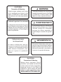
CALIFORNIA
WARNING
Proposition 65 Warning
Diesel engine exhaust and some
of its constituents are known to the
State of California to cause cancer,
birth defects and other reproductive
harm.
The engine exhaust from this product
contains chemicals known to the State
of California to cause cancer, birth
defects or other reproductive harm.
Californie Proposition 65 Avertissement
Les échappements des moteurs diesel et certains
de leurs composés sont reconnus par l’Etat de
Californie pour être cancérigènes, provoquer
des défauts congénitaux et d’autres dangers en
matière de reproduction.
Avertissement
L’émission du moteur de ce matériel contient des produits chimiques que l’Etat de
Californie considère être cancérigènes,
provoquer des défauts congénitaux et
d’autres dangers en matière de reproduction.
California Advertencia
Advertencia
de la Proposicion 65
El estado de California hace saber que
los gases de escape de los motores diesel
y algunos de sus componentes producen
cáncer, defectos de nacimiento y otros
daños en el proceso de reproducción
humana.
El estado de California hace saber que los
gases de escape de este producto contienen
productos quÍmicos que producen cáncer,
defectos de nacimiento y otros daños en
el proceso de reproducción humana.
CALIFORNIA
Proposition 65 Warning
Battery posts, terminals, wiring
insulation, and related accessories
contain lead and lead compounds,
chemicals known to the State of
California to cause cancer and birth
defects or other reproductive harm.
WASH HANDS AFTER HANDLING.
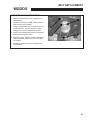
WOODS
IMPORTANT MESSAGE
TO THE DEALER:
Assembly and proper installation of this product is the responsibility of the Woods® dealer. Read manual
instructions and safety rules. Make sure all items on the Dealer’s Pre-Delivery and Delivery Check Lists in
the Set-Up instructions are completed before releasing equipment to the owner.
The dealer must complete the Product Registration online at the Woods Dealer Website or complete the
mail-in form included with the Operator’s Manual. If using the mail-in form, the dealer is to return the prepaid
postage portion to Woods, give one copy to the customer, and retain one copy. Failure to register the product
does not diminish customer’s warranty rights.
TO THE OWNER:
Read the Operator’s Manual before operating your Woods equipment. The information presented will prepare
you to do a better and safer job. Keep the manual handy for ready reference. Require all operators to read
the Operator’s Manual carefully and become acquainted with all adjustment and operating procedures before
attempting to operate the equipment. Replacement manuals can be obtained from your dealer. To locate
your nearest dealer, check the Dealer Locator at www.WoodsEquipment.com, or in the United States and
Canada call 1-800-319-6637.
The equipment you have purchased has been carefully engineered and manufactured to provide dependable
and satisfactory use. Like all mechanical products, it will require cleaning and upkeep. Lubricate the unit as
specified. Observe all safety information in this manual and safety decals on the equipment.
For service, your authorized Woods dealer has trained mechanics, genuine Woods service parts, and the
necessary tools and equipment to handle all your needs.
Use only genuine Woods service parts. Substitute parts will void the warranty and may not meet standards
required for safe and satisfactory operation. Record the model number and serial number of your equipment
in the spaces provided:
Model: _______________________________ Date of Purchase: _____________________
Serial Number: (located on left side panel near cut-off switch.)____________________________
Provide this information to your dealer to obtain correct repair parts.
ALITEC™
BMP®
CENTRAL FABRICATORS®
GANNON®
GILL®
WAIN-ROY®
WOODS®
12-2009
3
WOODS
TABLE OF CONTENTS
FIGURES
PAGE
SAFETY........................................................................................................................................................ 5-11
SET-UP INSTRUCTIONS...........................................................................................................................12-13
LABELS......................................................................................................................................................14-17
CONTROLS................................................................................................................................................18-21
PRE-OPERATION CHECKLIST...................................................................................................................... 22
OPERATION...............................................................................................................................................23-25
MAINTENANCE CHART................................................................................................................................. 26
MAINTENANCE RECORD.............................................................................................................................. 27
MAINTENANCE.........................................................................................................................................28-34
ADJUSTMENTS.........................................................................................................................................35-39
BELT REPLACEMENT...............................................................................................................................40-41
NOTES............................................................................................................................................................ 42
PARTS SECTION............................................................................................................................................ 43
FRAME-ENGINE/CLUTCH ASSY........................ FIGURE 1.................................................................... 44, 45
TRANSAXLE ASSY.............................................. FIGURE 2.................................................................... 46, 47
FUEL TANK/BUMPER & CONTROL PANEL....... FIGURE 3.................................................................... 48, 49
FUEL VALVE & COVER PLATE........................... FIGURE 4.................................................................... 50, 51
DECK LIFT ASSEMBLY....................................... FIGURE 5.................................................................... 52, 53
CASTER ASSEMBLY........................................... FIGURE 6.................................................................... 54, 55
KICKPLATE/SEAT ASSEMBLY............................ FIGURE 7.................................................................... 56, 57
STEERING........................................................... FIGURE 8.................................................................... 58, 59
PARKING BRAKE................................................ FIGURE 9.................................................................... 60, 61
WIRE HARNESS.................................................. FIGURE 10.................................................................. 62, 63
36" SIDE DISCHARGE........................................ FIGURE 11.................................................................. 64, 65
48" SIDE DISCHARGE........................................ FIGURE 12.................................................................. 66, 67
52" SIDE DISCHARGE........................................ FIGURE 13.................................................................. 68, 69
61" SIDE DISCHARGE........................................ FIGURE 14.................................................................. 70, 71
BELTS-CUTTERDECK......................................... FIGURE 15.................................................................. 72, 73
DECALS-POWERUNIT........................................ FIGURE 16.................................................................. 74, 75
4
SAFETY
WOODS
NOTICE !!!
This symbol means:
Unauthorized modifications may present extreme
safety hazards to operators and bystanders and
could also result in product damage.
ATTENTION!
BECOME ALERT!
Your safety and the safety of others is involved.
Woods strongly warns against, rejects and disclaims
any modifications, add-on accessories or product
alterations that are not designed, developed, tested
and approved by Woods Engineering Department.
Any Woods product that is altered, modified or
changed in any manner not specifically authorized
after original manufacture–including the addition of
“aftermarket” accessories or component parts not
specifically approved by Jacobsen–will result in the
Woods Warranty being voided.
Any and all liability for personal injury and/or property
damage caused by any unauthorized modifications,
add-on accessories or products not approved by
Woods will be considered the responsibility of the
individual(s) or company designing and/or making
such changes. Woods will vigorously pursue full
indemnification and costs from any party responsible
for such unauthorized post-manufacture modifications
and/or accessories should personal injury and/or
property damage result.
Signal word definitions:
The signal words below are used to identify levels
of hazard seriousness. These words appear in this
manual and on the safety labels attached to Woods
machines. For your safety and the safety of others,
read and follow the information given with these
signal words and/or the symbol shown above.
DANGER indicates an imminently hazardous
situation which, if not avoided, will result in death
or serious injury.
WARNING indicates a potentially hazardous
situation which, if not avoided, could result in
death or serious injury.
CAUTION indicates a potentially hazardous situation
which, if not avoided, may result in minor or moderate
injury. It may also be used to alert against unsafe
practices or property damage.
CAUTION used without the safety alert symbol
indicates a potentially hazardous situation which, if
not avoided, may result in property damage
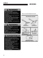
MODEL NUMBER: This number appears on
sales literature, technical manuals and price lists.
SERIAL NUMBER: This number appears only
on your mower. It contains the model number
followed consecutively by the serial number.
Use this number when ordering parts or seeking
warranty information.
* Serial Plate located on left side panel near cut-off switch.
5
SAFETY
WOODS
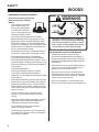
PREPARING FOR SAFE OPERATION
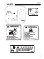
WARNING
Operator preparation and training
Read the Operation & Safety
Manual
- If an operator or mechanic
cannot read English, it is
the owner's responsibility
to explain this material to
them. If any portion of this
material is unclear, contact
your factory representative for clarification.
All rotary lawnmowers are potentially
dangerous. They can amputate hands and
feet and throw objects. Failure to follow
these safety and operating instructions
could result in serious injury or death.
- Become familiar with the safe operation of the
equipment, operator controls and safety signs.
Know how to stop the engine and attachments
quickly in an emergency. Do not operate or allow
another person to operate this machine if there
are any questions about safety.
-
All operators and mechanics should be trained.
The owner is responsible for training the users.
-
Wear appropriate clothing, including long
trousers and safety goggles or safety glasses
with side shields when operating mower. Do not
operate barefoot or wearing open sandals. Long
hair, loose clothing or jewelry may get tangled in
moving parts.
Site preparation and circumstances
-
Evaluate the terrain to determine what
accessories and attachments are needed to
properly and safely perform the job. Only use
accessories and attachments approved by the
manufacturer.
-
Clear the area to be mowed of objects such as
rocks, toys, wire or other debris that may be
picked up or thrown by the mower.
-
Wear hearing protection.
-
Never allow underage children, unskilled
or improperly trained people operate this
equipment. Local regulations can restrict the age
of the operator.
-
Be sure the area is clear of pets and people,
especially young children. Never assume they
will remain where you last saw them. Stop the
machine if any enter the area.
-
Data indicates that those operators age 60 years
and above are involved in a large percentage of
riding mower-related injuries. Those operators
should evaluate their ability to operate the riding
mower safely enough to protect themselves and
others from injury.
-
Mow only in daylight or in good artificial light.
-
Do not mow wet grass as tires may lose traction.
-
Do not carry passengers, especially small
children. They may fall off and be seriously
injured.
- Keep warning labels and this operator's manual
legible and intact. Replacement labels and
manuals are available from the factory.
- Do not operate machine while under the
influence of drugs or alcohol.
-
6
The owner/user can prevent and is responsible
for accidents or injuries occurring to themselves,
other people or property.
SAFETY
WOODS
Machine preparation
OPERATING SAFELY
-
Check operator presence interlock system and
brake operation. Adjust or repair any problems
before using.
In general
-
Use extra care when loading or unloading the
machine into a trailer or truck.
-
Do not tamper with or defeat safety devices.
Keep guards, shields and interlock safety devices
in place and in proper working condition. They
are for your protection.
-
Slow down and use caution when making turns
and crossing roads and sidewalks. Stop blades if
not mowing.
-
-
Keep all fasteners such as nuts, bolts and pins
well secured.
Do not run the engine in an enclosed area where
dangerous carbon monoxide fumes can collect.
-
-
Visually inspect blades, blade bolts and the cutter
assembly for wear or damage. Replace worn or
damaged blades and bolts to preserve balance.
Do not place your foot on the ground while
operating the machine.
-
Before operating, lower the discharge chute,
install the mulcher or put the entire grass catcher
in place.
-
Keep clear of the discharge opening at all times.
Never direct the discharge toward a bystander.
Stop operation if someone approaches.
-
Keep washout ports and other mower housing
service openings closed when mowing.
-
Use care when pulling loads or using heavy
equipment.
- Use only approved drawbar hitch points.
- Limit loads to those you can safely control.
- Do not turn sharply. Use care when reversing.
- Use counterweight(s) or wheel weights when
suggested in the operator's manual.
-
Verify that machine and attachments, if any, are
in good operating condition.
-
Do not engage blades until ready to mow.
-
Never leave a machine unattended. Always turn
off blades, set parking brake, stop engine and
remove key before dismounting.
7
SAFETY
WOODS
Starting
Interrupting operation
-
Start only according to instructions in this manual
or on the machine.
-
Before attempting to start the engine, make sure:
- the parking brake is on;
- the PTO is disengaged;
- the traction drive is in NEUTRAL.
-
Before leaving the operator's position:
- Park on level ground.
- Disengage the PTO.
- Set the parking brake.
- Shut off the engine and remove the key.
-
-
When starting the engine, make sure hands and
feet are clear of the blades.
Disengage the PTO and wait until the blades quit
rotating:
- before raising cutterdeck;
- when not mowing;
- for transport;
- when crossing surfaces other than grass.
-
Do not start the machine while standing in front
of the discharge chute or with the chute directed
at someone.
-
Do not engage PTO at full throttle. Throttle to
idle or lowest possible engine speed.
-
Do not change engine governor settings or
overspeed the engine. Operating the engine
at excessive speed can increase the hazard of
personal injury.
-
-
8
Stop the engine, disengage the PTO, set parking
brake and wait until the blades quit rotating and
lower cutting unit:
- before refueling;
- before removing grass catcher;
- before making height adjustment unless the
adjustment can be made from the operator's
position.
Stop the engine, disengage the PTO, set parking
brake and disconnect the spark plug wire(s) or
remove the key:
- before clearing blockages or unclogging chute;
- before checking, cleaning or working on the
machine;
- after striking a foreign object. Inspect the
machine for damage and make repairs before
restarting;
- if the machine begins to vibrate abnormally:
shut off machine immediately. Inspect and
make repairs as needed before restarting;
- except for repairs or adjustments as specifically
noted, such as for carburetor adjustment,
where the engine must be running. Keep
hands and feet clear of moving parts in these
circumstances.
-
Allow the blades to come to a complete stop
when stopping operation to clear blockages,
unclog, inspect the machine, do maintenance or
repair.
-
Reduce the throttle setting during engine shutdown and, if the engine is provided with a shutoff valve, turn the fuel off at the conclusion of
mowing.
SAFETY
WOODS
MANEUVERING SAFELY
In general
-
Slow down before turning.
-
-
Do not mow in reverse unless absolutely
necessary. Always look behind and down
for small children and pets before and during
backing.
Use extra care with grass catchers or other
attachments. These can change the stability of
the machine.
-
Remove obstacles such as rocks, tree limbs etc.
-
Avoid driving over obstacles such as ruts, holes,
rocks and roots whenever possible. Be alert to
dips and rises. Uneven terrain can overturn a
mower or cause it to slide. Tall grasses can hide
obstacles.
-
Do not mow drop-offs, ditches or embankments.
The machine could suddenly turn over if a wheel
runs over the edge or an edge caves in.
-
Follow the manufacturer's recommendations
for wheel weights or counterweights to improve
stability.
-
Do not mow slopes when grass is wet. Reduced
traction could cause sliding.
-
Be aware when approaching blind corners,
shrubs, trees, tall grass or other objects that may
obscure vision.
-
If tires lose traction, disengage the blades. If on
a slope, head downhill.
Mowing slopes
WARNING
Slopes are a major factor in
loss-of-control and tip over
accidents that sometimes lead
to severe injury or death. All
slopes require extra caution.
-
Do not mow on slopes if uneasy or uncertain.
Ultimate responsibility for safe operation on
slopes rests with the operator.
-
Do not mow excessively steep slopes.
-
On zero turn machines, mow across slopes, not
up and down.
-
Avoid starting or stopping on a slope. If tires
lose traction, disengage the blades and proceed
slowly straight down the slope.
-
With a zero turn machine, if tires lose traction
going down a slope, steering control may be
regained by speeding up.
-
Mid-mount zero turns (belly mounted deck) have
much greater traction pointed up slope than
down slope. Be aware that traction may be lost
going down a slope. Do not operate a mid-mount
zero turn on slopes it cannot back up.
-
Keep all movement on the slopes slow and
gradual. Do not make sudden changes in speed
or direction.
-
Do not turn on slopes unless necessary, and then
turn slowly and downhill when possible.
-
Stay away from slopes if the ground is loose or if
caught in the rain during mowing.
-
Use lower speeds on a slope to avoid stopping or
shifting.
9
SAFETY
WOODS
WARNING
MAINTENANCE SAFETY
Blades
In general
-
Mower blades are sharp and
can cut. Use extra caution
when handling. Remove obstructions with care. Wrap the
blade(s) or wear gloves.
-
Be aware that rotating one blade on multi blade
mowers can cause other blades to rotate.
-
Only replace blades. Never straighten or weld
them.
-
Keep other persons away from blades.
-
Maintain machine according to manufacturer's
schedule and instructions for maximum safety
and best mowing results.
-
Park machine on level ground.
-
Never allow untrained personnel to service machine.
-
Adjust or repair only after the engine has been
stopped and the blades have quit rotating.
-
Inspect grass catcher components regularly. If
worn, damaged or deteriorated, they may expose
moving parts or allow objects to be thrown.
-
Replace parts if worn, damaged or faulty.
For best results, always replace with parts
recommended by the manufacturer.
-
Disconnect battery or remove spark plug wire(s)
before making any repairs. Disconnect the
negative terminal first and the positive last. Reconnect positive first and negative last.
-
Do not dismantle the machine without releasing
or restraining forces which may cause parts to
move suddenly.
-
Provide adequate support, e.g. jack stands for
lifted machine or parts if working beneath.
-
Do not put hands or feet near or under rotating
parts.
-
Clean up spilled oil or fuel thoroughly.
-
Replace faulty mufflers.
- To reduce fire hazards, keep the engine, muffler,
battery compartment and fuel storage area free
of grass, leaves, debris buildup or grease.
- Hydraulic fluid can penetrate skin, use paper
to check for leaks. Relieve hydraulic pressure
before disconnecting hoses. Make sure
connections are tight and hoses are in good
condition.
10
WARNING
Fuel
-
Gasoline and diesel fuels are
flammable; gasoline vapors
are explosive. Use extra care
when handling.
-
Store only in containers specifically designed for fuel.
-
When refueling or checking fuel level:
- Stop the engine and allow to cool;
- Do not smoke;
- Refuel outdoors only;
- Use a funnel;
- Do not overfill;
- If fuel is spilled, do not attempt to start the
engine until the spill is cleaned up and vapors
have cleared.
Sparks from static electricity can start fires or cause
explosions. Flowing fuel can generate static
electricity. To prevent static electricity sparks:
- Keep containers electrically grounded. Do not fill
containers in a vehicle or on a truck or trailer bed
with a plastic liner. Fill containers on the ground
away from the vehicle.
-
When practical, remove gas powered equipment from the truck or trailer and refuel it on the
ground. If equipment must be refueled on the
truck or trailer, refuel from a portable container
rather than a dispenser nozzle.
-
Keep the dispenser nozzle in contact with the rim
of the fuel tank or container opening until fueling
is complete. Do not use a nozzle lock-open
device.
-
Replace caps on fuel cans and tanks securely.
SAFETY
WOODS
BATTERY
WARNING
Battery acid is caustic and fumes
are explosive and can cause
serious injury or death.
To reduce the risk of personal
injury when working near a battery:
- When working with battery
acid, use protective equipment
such as, but not limited to, goggles, face shield,
rubber gloves and apron.
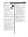
JUMP STARTING
1. Be sure the jumper cables are in good condition.
Turn off the ignition and all electrical accessories
on both machines.
2. Position the machine with a good (charged) battery next to but not touching the machine with the
dead battery so jumper cables will reach.
3. When making cable connections:
-
Avoid leaning over a battery.
-
Do not expose a battery to open flames or
sparks.
-
Be sure batteries with filler caps are properly
filled with fluid.
-
Do not allow battery acid to contact eyes or skin.
Flush any contacted area with water immediately
and get medical help.
-
Charge batteries in an open, well ventilated area,
away from sparks and flames. Unplug charger
before connecting or disconnecting from battery. STORAGE AND TRANSPORTATION
-
Stop the engine and allow to cool before storing.
-
Drain the fuel tank outdoors only.
- Store fuel in an approved container in a cool, dry
place.
-
Keep the machine and fuel containers in a locked
storage place to prevent tampering and to keep
children from playing with them.
-
When the machine is to be parked, stored or left
unattended, lower the cutterdeck unless a positive mechanical lock is used.
-
Do not store the machine or fuel container near
heating appliances with an open flame such as a
water heater or an appliance with a pilot light.
-
Keep gasoline storage area free of grass, leaves
and excessive grease to reduce fire hazard.
-
Clean grass and debris from cutting units, drives,
mufflers and engine to help prevent fires.
- make sure the clamps do not touch anywhere
except to intended metal parts,
- Never connect a positive ("+" or red) terminal
to a negative ("–" or black) terminal.
- Make sure the cables won't get caught in any
parts after the engines are started.
4. Connect one end of the first jumper cable to the
positive terminal on one battery. Connect the
other end to the positive terminal on the other
battery.
5. Connect one end of the other cable to the
negative terminal of the machine with a good
(charged) battery. Make the final connection on
the engine of the machine to be started, away
from the battery.
6. Start the vehicle with the good battery, then the
machine with the discharged battery.
7. Remove the cables in the exact reverse order of
installation. When removing each clamp, take
care it does not touch any other metal parts while
the other end remains attached.
11
SET-UP INSTRUCTIONS
WOODS
Tools required for assembly
-
-
-
-
-
Wrecking bar
Claw hammer
Sockets: 1/2”, 15/16
Wrenches: 18mm, 1/2”, 9/16”, 3/4”, 15/16”
Tire pressure gauge
NOTE: All references below to the “right” or “left” are with respect to an operator at the controls.
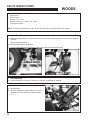
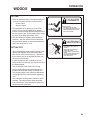
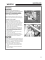
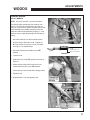
1. UNCRATE UNIT
a) Discard packing materials. Loosen the caster wheel axle bolts and bumper bolts to remove the shipping
brackets.
Discard shipping brackets.
b) Re-install and tighten bumper bolts.
c) Tighten caster wheel axle bolts against caster axle spanner bushings to 80 ft/lbs.
2. TIRE PRESSURE
a) Set tire pressures to 14 lbs/in2 (1.0 kg/cm2). Tires are overinflated for shipping.
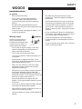
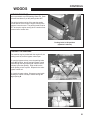
3. TRACTION LEVERS
a) Tighten bolt A.
b) Sit on the machine. Levers C may be moved to
upper set of holes in bar B for a better operator
fit.
12
SET UP INSTRUCTIONS
WOODS
4. FINAL PREPARATIONS
-
Check the engine and hydraulic oil levels. Top off with the correct oil if necessary. Use 10W30 motor oil
for the engine. Use fresh, clean 20W50 motor oil for the hydraulic system. See engine operation manual
for specified motor oil viscosity.
-
Charge battery and properly connect cables. See steps below.
Battery acid is caustic. Fumes are explosive and can cause serious injury or death.
Use insulated tools, wear protective glasses or goggles and protective clothing when working with batteries.
Read and obey the battery manufacturer’s instructions.
Be certain the ignition switch is OFF and the key has been removed before servicing the battery.
a) Verify battery polarity before connecting or disconnecting the battery cables.
b) When installing the battery, always assemble the RED, positive ( + ) battery cable first and the
ground, BLACK, negative ( - ) cable last.
c) Tighten cables securely to battery terminals and apply a light coat of silicone dielectric grease to terminals and cable ends to prevent corrosion. Keep terminal covers in place.
-
Read Operation and Safety Manual before starting. Operator Manual is located under the seat. Tilt seat
forward to access manual.
-
If deck does not cut level, see deck leveling procedure in the adjustments section of this manual.
-
Run engine at full RPM for 5 minutes before engaging blades to allow the engine to be fully lubricated
before load is applied.
-
Check the hydro stat neutral adjustment. Neutral is set at the factory but may require readjustment. See
adjustments section of this manual.
-
Do not use the machine without an approved grass collector, the grass discharge chute or mulching
plates correctly fitted.
13
LABELS
WOODS
14
LABELS
WOODS
15
LABELS
WOODS
DECAL IS LOCATED UNDER FOOTPLATE.
16
LABELS
WOODS
17
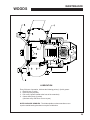
CONTROLS
WOODS
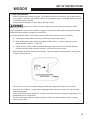
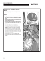
Keyswitch (K) - The keyswitch has three
positions: OFF, RUN, and START. Insert the key
and turn it clockwise to move the switch from OFF to
RUN. Turn it further to START and hold to engage
the starter. Release the key and the switch will return
to RUN from START. Turn the key counterclockwise
to OFF to stop the engine.
Throttle (T) - Move the throttle lever forward to
increase engine speed until the maximum governed
engine RPM is reached. Move the lever rearward to
decrease engine speed until the engine reaches its
idle speed.
Choke (C)
For Kawasaki Engines, pull the choke control out to
set the choke ON. Push it in to set the choke OFF.
Power Take Off (PTO) Switch (P) The operator must be in the seat when engaging the
PTO or the engine will kill. Pulling the PTO switch
out engages (turns on) the PTO and starts the blades
or other attachment. Pushing the PTO switch in
disengages (turns off) the PTO and stops the blades
or other attachment.
At operator's right side
NOTE: The PTO switch does not control
attachments powered by a separate engine.
- Disengage the PTO whenever you stop or leave
the operator’s position
- Shut off engine with the key and remove the
spark plug wires before making adjustments or
unplugging a clogged mower.
- Do not engage the PTO until ready to start
mowing.
12 VOLT POWER OUTLET (X) - A 12 volt
power outlet is provided to operate 12 volt personal
accessories.
18
Below seat
CONTROLS
WOODS
FUEL SELECTOR VALVE (U)
The fuel tank selector valve is located behind the
seat.
The fuel tank selector valve has three positions:
Off: The tank selector is off when the lever points
down. The selector should be off whenever the
machine is transported or stands unused for any
length of time. Shutting off the fuel supply avoids the
possibility of flooding should any dirt get under the
carburetor float needle. Leaving the tank selector in
either tank position can allow severe flooding, which
may ruin the engine by diluting the oil.
Right Tank: Fuel flows from the right tank when the
selector is turned 1/4 turn toward the right.
Left Tank: Fuel flows from the left tank when the
selector is turned 1/4 turn toward the left.
19
CONTROLS
WOODS
Reverse movement - To move the machine straight
back, pull both traction levers back equally from their
neutral position. Reverse speed increases as the
levers are moved back farther. Maximum reverse
speed is reached when the levers hit the rear of the
forward-reverse slot. When moving in reverse, pushing the levers forward slows the machine, and the
machine stops when the neutral position is reached.
NOTE: Reverse is spring loaded to return to neutral.
This spring resistance may be felt when moving the
traction levers into reverse. When the levers are
released in reverse, spring tension will slowly return
them to the neutral position.
Lift and traction levers
(operator's right side)
Steering - To steer, move one lever forward and
one back.
Lift lever (F) - Used to raise the cutterdeck to
Turns during forward movement:
maximum height for transport, curb climbing or blade
changing. To return to preset height of cut, lower lift
lever until it contacts height of cut pin A.
-
Right turn - move the right traction lever back
toward neutral to slow the right drive wheel.
-
Left turn - move the left traction lever back toward neutral to slow the left drive wheel.
Traction Levers (L) - Each of the two
traction levers controls the drive wheel located on
the same side. They control the forward and reverse
movement of the machine, provide steering and also
provide dynamic braking.
Turns during reverse movement:
-
Reverse right turn - move the right traction lever
forward toward neutral to slow the right drive
wheel.
The operator must be in the seat and the parking
brake must be OFF to engage the traction drive.
To engage traction drive, move the traction levers
toward the center of the machine until they are out of
neutral lock slot S.
-
Reverse left turn - move the left traction lever
forward toward neutral to slow the left drive
wheel.
Forward movement - To move the machine straight
ahead, push both traction levers forward equally from
their neutral position. Forward speed increases as
the levers are moved farther forward from the neutral
position. Maximum forward speed is reached when
the levers hit the front of the forward-reverse slot.
When traveling forward, pulling the traction levers
rearward slows the machine. The machine stops
when the neutral position is reached.
20
Slow, sweeping turns are made with both traction
levers on the same side of neutral and slightly
apart. True zero radius turns about the center of the
machine are made by having one lever in reverse
while the other is in forward. By varying the relative
positions of the two levers, the rate of turn is varied to
suit the mowing situation.
Slow down before making sharp turns. The machine
is capable of turning very rapidly when the levers are
moved further apart from each other. Loss of control
and/or turf damage may result.
CONTROLS
WOODS
Parking brake (R) - Pull the parking brake
lever up and back to put the parking brake ON. Push
it forward and down to put the parking brake OFF.
The parking brake must be ON to start the engine.
It must also be ON to keep the engine running if the
operator leaves the seat. The parking brake must be
OFF to keep the engine running when a traction lever
is moved out of neutral lock.
Parking brake in ON position
(operator's left side)
Pushing the machine
The machine may be pushed with the engine off, the
parking brake off, and the bypass valves open.
To open the bypass valves, move the parking brake
to the OFF position, then lift and pull bypass control
rod C through the large opening D, until the control
rod stop is past the opening. Drop rod C into the
small opening to lock in place. Repeat for the other
bypass control rod.
To close the bypass valves, lift bypass control rod C
allowing the control rod stop to retract through the
large opening D.
21
PRE-OPERATION CHECK LIST
WOODS
PRE-OPERATION CHECK LIST
(OPERATOR’S RESPONSIBILITY)
___ Review and follow all safety rules and safety
decal instructions.
___ Check that all safety decals are installed and in
good condition. Replace if damaged.
___ Check to make sure all shields and guards
are properly installed and in good condition.
Be sure that either the discharge shield or
complete vacuum attachment is installed.
___ Check that all hardware is properly installed.
and secured.
___ Check that equipment is properly and securely
attached to power unit.
___ Check to be sure engine is free of dirt and
debris. Pay particular attention to the cooling
fins, governor parts and muffler. Clean air
intake screen. Check air cleaner; service if
necessary.
22
___ Never allow riders.
___ Inspect area and remove stones, branches or
other hard objects that might be thrown,
causing injury or damage.
___ Clean area around oil fill dipstick. Remove
dipstick and check to be sure oil is in operating
range (between marks on dipstick). Add oil if
necessary but Do Not Overfill. Install dipstick
assembly firmly until cap bottoms out on tube.
Dipstick assembly must always be secured into
fill tube when engine is running.
___ Check all lubrication points and grease as
instructed in manual.
___ Check hydrostatic fluid level. Check to be sure
cooling fins on hydro stat are clean.
___ Perform a functional check of the safety
interlock system each time you operate the
unit.
OPERATION
WOODS
FUELING
- Fill fuel tank with good quality, clean, unleaded
regular gasoline. Do not use hi-test fuel.
- Use a funnel to avoid spilling.
OPERATOR PRESENCE
Interlock System
To start the engine:
- The PTO switch must be OFF.
- Both traction levers must be in the neutral lock
position.
WARNING
- The parking brake must be ON.
To operate the machine:
1. The operator must be in the seat or engaging the
PTO will kill the engine.
TO CHECK OR ADD FUEL:
– Do it outdoors
2. The parking brake must be OFF and the operator must be in the seat, or moving a traction lever
from the neutral lock position will kill the engine.
– Do not smoke
– Stop engine; allow to cool
– Fill to one inch below bottom
of filler neck
STARTING THE ENGINE
– Do not overfill
– Clean up spilled fuel
Before starting the engine
- Be familiar with all controls, how each functions
and what each operates.
- Check the engine oil level and add if necessary.
Using the fuel selector valve, select which tank
will supply fuel
1. Turn the key to operate the electric starter to start
the engine. Release the key when the engine
starts.
2. If the engine does not start immediately, do not
crank for more than 10 seconds at a time. Allow
60 seconds for the starter motor to cool down
between starting attempts to prevent the starter
motor from burning out.
3. If the choke is ON when the engine starts,
gradually back it off until the engine runs with no
choke at all.
- Choke: For cold starts, set the throttle lever to the
half-open position and pull the choke out to the
ON position. For warm starts set the throttle to
the half-open position and the choke to the OFF
position.
23
OPERATION
WOODS
OPERATING NOTES
Driving
- Practice at slow engine and travel speeds with the
PTO off until fully familiar with the controls.
1. With the PTO disengaged, move the parking
brake to OFF.
- For normal cutting the throttle should be set at the
full open position. By using the traction levers to
speed up or slow down the machine during use,
maximum control and cutting efficiency can be
maintained.
2. Move both traction levers out of neutral lock.
- Using the machine at less than full throttle in
heavy conditions will cause the engine to labor
and result in excessive wear and can cause damage to the transaxles.
3. Push both traction levers forward evenly to drive
forward in a straight line. Pull both traction levers
back evenly to drive backward in a straight line.
4. Steering - Move one lever forward and one back.
Turns during forward movement:
-
Right turn - move the right traction lever back
toward neutral to slow the right drive wheel.
-
Left turn - move the left traction lever back toward neutral to slow the left drive wheel.
Turns during reverse movement:
-
Reverse right turn - move the right traction lever
forward toward neutral to slow the right drive
wheel.
-
Reverse left turn - move the left traction lever
forward toward neutral to slow the left drive
wheel.
use caution when making turns. Slow down before
making sharp turns to help maintain control and to
prevent torn turf from skidding or spinning tires. To
help prevent turf damage, keep both drive tires moving whenever a turn is made.
TIP: The best way to make a sharp "zero" turn is to
come to a stop, get the machine moving in reverse
with both drive wheels and then power the machine
around with the outside wheel. This technique keeps
the drive tires turning and results in less turf damage.
24
OPERATION
WOODS
Cutting
1. Place the discharge chute in the down position or
correctly fit a grass collector or mulcher plate.
2. Sit in the seat.
3. Start the engine.
4. Turn the blades on by pulling up on the PTO
switch. Do not start the blades at full throttle.
Instead, use the slowest throttle setting that will allow the engine to pick up the blade load to reduce
the wear on the belts and electric clutch.
5. After the blades are rotating, set the throttle to
maximum. Use the traction levers to obtain the
required cutting speed, to steer around obstacles
and to turn at the end of a cut.
DANGER
ROTATING BLADES
– KEEP HANDS AND FEET AWAY.
– STOP ENGINE AND LET BLADES STOP
BEFORE REMOVING GRASS COLLECTOR OR UNCLOGGING.
WARNING
THROWN OBJECTS
CUTTING TIPS
- When mowing large areas, start by turning to the
right so that clippings will be discharged away
from shrubs, fences, driveways, etc. After two or
three rounds, mow in the opposite direction, left
hand turns, until finished.
– Keep area clear of people
and pets.
– Remove objects blade may
strike and throw.
– Stop blades to cross gravel
areas
– Do not operate without chute,
mulcher or entire grass
CATCHER IN PLACE.
- If grass is extremely tall, it should be mowed
twice, the first cut relatively high, the second cut to
the desired height.
- Use the left side of the mower for trimming.
- Choose cutting directions so that clippings are
thrown onto areas that already have been cut.
This method results in the most even distribution
of clippings and more uniform, better appearing
cuts.
- Use a different mowing pattern each time where
possible. This helps prevent rutting and leads
to a more uniform cut by keeping the grass from
always laying the same way.
25
MAINTENANCE CHART
WOODS
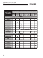
MAINTENANCE
OPERATION
Maintenance is an ongoing job. These intervals are maximum times betw een
maintenance operations. Perform more often under severe conditions.
FIRST 5
HOURS
BEFORE
EACH
U SE
EVERY
25
HOURS
EVERY
50
HOURS
EVERY
100
HOURS
EVERY
200
HOURS
YEARLY
ENGINE
Consult the engine manual for additional information and instructions
Check/Top Up
Oil Level
X
C h eck F o r L eaks
X
Clean Air Intake
Screen
X
Clean Air Cleaner
Precleaner
X
Clean Air Cleaner
Element
X
Clean Cooling Fins
Change Oil And
Filter
X
See engine manufacturer's manual
X
Check/Replace
Spark Plugs
X
TRANSAXLE
Check Oil Level
X
C h eck F o r L eaks
X
Change Oil And
Filter
X
MACHINE
Check Interlock
Operation
X
Check Tire
Pressures
X
Check/Top Up
Battery
Lubricate All Points
26
X
X
MAINTENANCE RECORD
WOODS
NOTES
________________________________________________
________________________________________________
________________________________________________
________________________________________________
________________________________________________
________________________________________________
________________________________________________
________________________________________________
________________________________________________
________________________________________________
________________________________________________
________________________________________________
________________________________________________
GENERAL
DATE
HRS
DATE
HRS
DATE
HRS
DATE
HRS
D ATE
HRS
DATE
HRS
C h ec k T i r e P r es s u r es
L u b r i c at e A l l P o i n t s
C h ec k N u t s & B o l t s
ENGINE
Ch ec k Oil L ev el
Ch an g e Oil
C l ean
A i r C l ean er E l em en t
C l ean C o o l i n g F i n s
R ep l ac e
A i r C l ean er E l em en t
Clean & Gap
S p ar k P l u g s
TR A N S A X L E
Ch an g e Oil An d Filt er
NOTE: Af t er f ir s t 5 h o u r s o f o p er at io n c h an g e en g in e o il an d f ilt er.
27
MAINTENANCE
WOODS
CHECK DAILY
Operator Presence Interlock System - Start Operation
For the engine to crank, the parking brake must be on, the PTO (blades) off and traction levers in the neutral
lock position. Sit in the seat and check, one by one, if the engine will crank with the parking brake off, the
blades on, and either traction lever out of neutral lock.
Operator Presence Interlock System - Run Operation
The operator must be in the seat for the engine to run with the parking brake off, the traction levers moved out
of the neutral lock position, or the blades on. To check:
1. Start the engine and run at 1/2 throttle with the operator on the machine but raised off the seat.
2. One by one: move the parking brake to the OFF position, traction levers out of the neutral lock position
(check each independently), and turn the blades on. Each check should kill the engine after 1/2 second.
(A 1/2 second delay is built into the system to prevent engine cutout when traversing rough terrain.)
Repair machine before using if the Operator Presence Interlock System does not operate correctly in start or
run. Contact your authorized Schiller Grounds Care, Inc. dealer.
Hardware
Tighten any nuts and bolts found loose. Replace any broken or missing cotter pins. Repair any other problems before operating.
Tire pressure
Tires should be kept inflated to 14 lbs/in2 (1.0 kg/cm2). Improper tire inflation can cause rapid tire wear and
poor traction. Uneven inflation can cause uneven cutting. Overinflation of caster tires can cause casters to
"wobble" on hard surfaces.
BATTERY
Battery acid is caustic and fumes
are explosive and can cause serious injury or death.
4. Check the electrolyte level every 100 hours of
operation or yearly, whichever comes first. Top
off with distilled water if necessary.
Use insulated tools, wear protective glasses or
goggles and protective clothing when working with
batteries. Read and obey the battery manufacturer’s
instructions.
NOTE: Sealed batteries cannot be checked or
topped off.
Be certain the ignition switch is OFF and the key has
been removed before servicing the battery.
1. Verify battery polarity before connecting or disconnecting the battery cables.
2. When installing the battery, always assemble
the RED, positive ( + ) battery cable first and the
BLACK ground, negative ( - ) cable last.
3. When removing the battery, always remove the
BLACK ground, negative ( - ) cable first and the
red, positive ( + ) cable last.
28
5. Clean the cable ends and battery posts with steel
wool. Use a solution of baking soda and water
to clean the battery. Do not allow the solution to
enter into the battery cells.
6. Tighten cables securely to battery terminals and
apply a light coat of silicone dielectric grease to
terminals and cable ends to prevent corrosion.
Keep terminal covers in place.
MAINTENANCE
WOODS
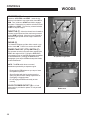
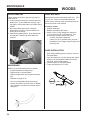
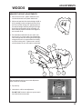
LUBRICATION
Every 50 hours of operation, lubricate the following points (1-3) with grease:
1. Deck lift lever (1 point)
2. Deck lift pivots (4 points)
3. Pull arms (2 points located at the front of the cutterdeck)
4. Caster wheel pivots (2 points)
(Lubricate every 500 hours or once a year)
NOTE ON BLADE SPINDLES - The blade spindles on these machines use a
superior sealed bearing that does not require relubrication.
29
MAINTENANCE
WOODS
ENGINE OIL
Do not perform engine maintenance without the
engine off, spark plug wires disconnected and PTO
disengaged.
AFTER FIRST FIVE (5) HOURS
While the engine is warm:
1. Release the oil drain hose assembly from the
engine clip J. Lay hose assembly over the frame
edge or through the frame cutout, which ever is
most convenient.
2. Remove the rubber cap D from the tip of the
hose assembly and turn the drain valve to allow
oil to drain from the engine. Dispose of used oil
in accordance with local requirements.
3. Clean drain valve and tighten the plastic portion
of the drain valve back into the metal portion of
the valve. Replace rubber cap over the tip of the
valve. Replace hose assembly back into engine
clip.
4. Change oil filter.
5. Fill the crankcase with fresh oil to the full mark.
Do not overfill. See engine manual for oil
specifications.
DAILY
1. Check oil level with the dipstick.
2. If oil is needed, add fresh oil of proper
viscosity and grade. See engine manual for oil
specifications. Do not overfill.
3. Replace dipstick before starting engine.
PERIODIC OIL CHANGES
1. See engine manual for oil and filter change intervals after the break-in period.
2. Follow instructions for first oil change, above.
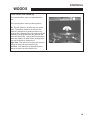
Spark Plugs
Remove each plug and check condition.
-
Good operating conditions are indicated if the plug has a light coating of grey or tan deposit.
-
A white blistered coating indicates overheating. A black coating indicates an “over rich” fuel mixture. Both
may be caused by a clogged air cleaner or improper carburetor adjustment.
-
Do not sandblast, wire brush or otherwise attempt to repair a plug in poor condition. Best results are
obtained with a new plug.
-
Set plug gap as specified in engine manual..
FUEL FILTER
An in-line fuel filter is located in the fuel supply line. Inspect at every oil change to make sure it is clean and
unobstructed. Replace if dirty.
30
MAINTENANCE
WOODS
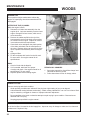
AIR CLEANER
Clean and replace the air cleaner element as specified in the service chart. Uneven running, lack of
power or black exhaust may indicate a dirty air
cleaner.
1. Unclamp end cover C and remove existing
cleaner element A.
2. Insert new element A and replace cover C.
Ensure breathing port B is pointing down and
towards the front of the tractor.
CLEANING MACHINE
WASHING MACHINE
Clean the machine after use. The machine will run
cooler and last longer if kept free of clippings and
other debris. A clean machine also reduces the risk
of fire due to accumulation of combustible debris and
chaff
CAUTION: Improperly washing a machine can cause
water to enter bearings and other components. This
can greatly reduce component life.
Brush or blow clippings and debris off the cutterdeck
and engine deck.
– Do not use a pressure washer. Do not direct
water at bearings or seals. High pressure water
can blow past seals ad enter seal bearings.
– Allow the machine to cool down before washing.
Water on a warm machine can be sucked into
sealed bearings as they cool.
– Avoid getting electrical connections wet. Water
can cause electrical faults and corrosion of electrical components.
31
MAINTENANCE
WOODS
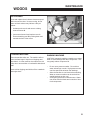
ENGINE COOLING
Continued operation with a clogged cooling system
will cause severe overheating and can result in engine damage.
-
Daily: Clean air intake screen V.
-
Every 100 hours: Clean cooling fins beneath
blower housing H with reference to information in
the engine manufacturer's manual.
SPECIFIC TORQUES
B LADE BOLTS
70 FT-LBS (95 Nm )
WHEEL HUB NUTS
150 FT-LBS (203 Nm)
ENGINE CRANKSHAFT BOLT
50 FT-LBS (68 Nm )
TRANSAXLE PULLEY NUT
28.3 - 41.6 FT-LBS (38 - 56 Nm)
TRANSAXLE DRAIN PLUG
15 - 20 FT-LBS (20 - 27 Nm)
TRANSAXLE FILTER
130 - 150 in-lbs (14.6 - 16.9 Nm)
PURGING TRANSAXLES
Due to the effects air has on efficiency in hydrostatic
drive applications, it is critical that it be purged from
the system.
These purge procedures should be implemented any
time a hydrostatic system has been opened to facilitate maintenance or any additional fluid has been
added to the system.
Purging may be required if the unit shows any of the
following symptoms:
32
- Noisy operation.
- Lack of power or drive after short term use.
- High operation temperature, excessive oil expansion.
1. Check the transaxle fluid, fill to proper level, if
required.
2. Raise the drive wheels off the ground. Support
unit with jack stands or other suitable means.
3. With the bypass valves open, and the engine
running, slowly move the control levers in both
forward and reverse directions 5 to 6 times. As
air is purged from the unit, the oil level will drop.
4. With the bypass valve closed, and the engine
running, slowly move the control levers in both
forward and reverse directions 5 to 6 times.
5. Stop engine. Check the transaxle fluid level, add
fluid as required.
6. It may be necessary to repeat steps 3-5 until all
the air is completely purged from the system.
When the transaxle moves forward and reverse
at normal speed, purging is complete.
MAINTENANCE
WOODS
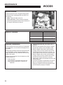
TRANSAXLES
Inattention to proper safety, operation, or
maintenance procedures could result in personal
injury, or damage to the equipment. Schiller
Grounds Care, Inc. recommends returning the
machine to your authorized Schiller Grounds
Care, Inc. dealer for service or repair.
Perform transaxle maintenance with the engine off,
spark plug wires disconnected and PTO disengaged.
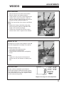
TRANSAXLE FLUID CHANGE
Change the transaxle fluid every 200 hours of
operation. It is essential that the exterior of the
transaxle be free of debris, prior to fluid maintenance.
1. Remove the three 1/4" filter guard screws and
filter guard A. Remove the oil filter B from the
transaxle and discard. Dispose of used oil in accordance with local requirements.
2. Wipe the filter base surface off and apply a film
of new oil to the gasket of the new replacement
filter. Install the new filter by hand, turn 3/4 to
one full turn after the filter gasket contacts the
filter base surface.
3. Re-install the filter guard and torque the three
screws to 65 in. lbs. each.
4. Remove cap C, fill the transaxles through the
expansion tank D with approximately 2 quarts of
SAE 20W-50 engine oil PER TRANSAXLE.
Do not overfill! If you overfill the transaxle while the unit
is "cold", it may overflow as it reaches normal operating
temperatures. The oil level should not be above the
manufacturer's suggestions. This will allow the space
needed for the oil to expand as it warms up.
5. After starting engine, check the fluid level and
continue to add oil to overflow tank D to fill line
on tank.
6. Purge the transaxles, following the purging procedures on Page 31.
33
MAINTENANCE
WOODS
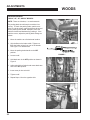
BLADE REMOVAL
BLADE Balance
Follow these instructions to prevent injury during
blade removal:
1. Loosen with a box wrench or a socket and long
breaker bar. To gain additional leverage, slip a
long pipe or thick-walled tube over breaker bar or
wrench.
2. Insert wood block A as shown, with grain
perpendicular to blade, to prevent blade from
turning when loosening.
3. Wear thickly padded gloves. Keep hands clear
of blade path. Blades may rotate when bolt
releases.
Blade balance must be maintained at 5/8 oz-in (19.4
g-cm) or less. Failure to keep blades balanced
causes excess vibration, wear, and shortened life of
most components of the machine.
To balance a blade:
1. Sharpen blade first.
2. Balance the blade at the center.
3. Attach a 1/8 oz (3.9 g) weight at a distance 5"
(127 mm) from center on the light end. This
should make the light end the heavy end:
- If it does, the blade is balanced.
- If does not, file or grind the heavy end until
the addition of the weight makes the light end
the heavy end.
Blade installation
1. Wear thickly padded gloves to prevent cuts from
the sharp blade.
2. Insert the blade bolt, in order, through the conical
washer (cup side toward the blade, as shown),
the blade, and the blade spacer.
3. Install assembly on the blade spindle.
4. Torque the blade bolt to 70 ft-lbs.
Sharpening
Blades may be sharpened by filing or grinding.
- Inspect blades before sharpening.
- Replace bent or cracked blades.
- Replace blades when the lift portion has worn
thin.
o
- Maintain cut angle at 30 .
- Do not overheat blades when sharpening.
- Always use Schiller Grounds Care, Inc.blades.
Use of another manufacturer’s blades may be
dangerous.
34
ADJUSTMENTS
WOODS
DECK LEVELING
1. Park the machine on a smooth, level surface.
Raise the deck to the transport position.
2. Lower the deck onto a set of equal height blocks
under the rear corners of the deck. Place another set of blocks under the front of the deck so
that the deck top is pitched forward 1/8".
NOTE: The front and rear of the deck are at different
heights.
3. Measure the height of the blade cutting edge
above the ground. Remove pin B and set the
height of cut lever E to that height
4. Loosen nuts on bolts G. Move bolts in slot to
remove slack in chain. Tighten nuts on bolts G.
Height of cut
The height of cut is set by moving height of cut pin B
to the hole designated for the height of cut desired.
To change the height of cut:
1. Lift the deck to the highest position.
2. Move pin B to the selected hole.
3. Lower the deck until the lift lever is stopped by
the pin.
NOTES:
-
Height of cut may vary due to the amount of
tread on the tires, tire diameter or inflation pressure.
DECK RollerS
The deck rollers are adjustable up and down to
provide improved deck flotation and scalping protection at various heights of cut. They are not intended
to ride continuously on the ground. Adjust no closer
than 3/8" (10mm) to the ground.
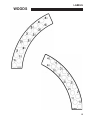
Height of cut ranges for roller adjustment
35
ADJUSTMENTS
WOODS
PARKING Brake
FOR 36", 42", 48", AND 52" MODELS
NOTE: There are 2 brakes, 1 on each transaxle.
The parking brake should keep the machine from
moving. To check the parking brake, park the machine on a level surface, open the bypass valves and
set the parking brake to ON. Attempt to move the
machine forward and backward by pushing it. If the
machine moves, adjust the parking brake linkage as
follows:
1. Move the machine to a flat horizontal surface.
2. Grip the flats on the brake rod A. Tighten nut
B on the brake rod until you run out of threads.
See Figure 1 for detailed view.
3. Move the parking brake handle to the OFF
position.
FIGURE 1
4. Loosen nut X.
5. Hold brake arm in the OFF position as shown in
Figure 2.
6. Adjust swivel U until swivel stud meets brake arm
hole in the OFF position.
7. Insert cotter pin into swivel U.
8. Tighten nut X.
9. Repeat Steps 1-8 on the opposite side.
FIGURE 2
36
ADJUSTMENTS
WOODS
PARKING Brake
FOR 61" MODELS
NOTE: There are 2 brakes, 1 on each transaxle.
The parking brake should keep the machine from
moving. To check the parking brake, park the machine on a level surface, open the bypass valves and
set the parking brake to ON. Attempt to move the
machine forward and backward by pushing it. If the
machine moves, adjust the parking brake linkage as
follows:
1. Move the machine to a flat horizontal surface.
2. Grip the flats on the brake rod A. Tighten nut
B on the brake rod until you run out of threads.
See Figure 1 for detailed view.
3. Move the parking brake handle to the OFF
position.
B
X
Tighten until you
runout of threads
FIGURE 1
4. Loosen nut X.
5. Hold brake arm in the OFF position as shown in
Figure 2.
6. Adjust linkage rod U until formed end of rod
meets brake arm hole in the OFF position.
7. Insert cotter pin into formed end of linkage rod U.
8. Tighten nut X.
9. Repeat Steps 1-8 on the opposite side.
FIGURE 2
37
ADJUSTMENTS
WOODS
HydrostatIC TRANSAXLE adjustmentS
A turnbuckle style hydro stat neutral adjustment is
provided.
Neutral:
1. Support the machine with the rear wheels off
the ground. Use jack stands or equivalent support. Do not rely only on mechanical or hydraulic
jacks.
2. Move the traction levers out into the neutral lock
position and raise the seat.
3. Disconnect the seat switch wire and temporarily
connect the two terminals with jumper wire J as
shown.
4. Start the engine and run at low speed.
5. Move parking brake to the OFF position.
6. Loosen jam nuts K at both ends of the control
rod L.
7. Rotate the control rod until the corresponding
wheel stops turning. Lock the control rod jam
nuts. Run the engine up to high idle and stroke
the traction levers forward and back to check the
adjustment. Move traction levers back to neutral
and readjust if necessary.
8. Repeat steps 6 and 7 for the opposite side.
9. Remove the jumper wire and reconnect the seat
switch.
38
ADJUSTMENTS
WOODS
ARM REST HEIGHT ADJUSTMENTS
1. Remove acorn nuts 1, plastic washers 2, arm
rest 3 and second set of plastic washers 4.
C C
B B
A A
2. Adjust carriage bolts 5 to desired height A, B, or
C by pushingg on the carriage bolts 5 until they
are free from the locking slot, adjusting them to
the desired height and then pulling the carriage
bolts 5 into the desired locking slot A, B, or C.
Bolts must be placed into slots a like heights or
arm rest will not fit.
3. Re-assemble washers 2 & 4, arm rest 3, and
acorn nuts 1 in reverse order from disassembly.
Hold carriage bolts 5 in lockting slots while tightening acorn nuts 1 to prevent them from falling
out of the locking slots. Tighten nuts 1 until desired resistance in arm rest rotation is acheived.
5
4
3
2
1
1
2
4
5
SEAT ADJUSTMENT
The seat plate allows from some seat adjustment
either forward or backward.
1. Flip seat up.
2. Use holes 1 or 2 for seat adjustment.
DO NOT USE holes 3 or 4 due to space restrictions with the document tube.
39
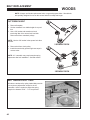
BELT REPLACEMENT
WOODS
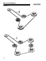
NOTE: Always use Woods replacement belts, not general purpose belts. Woods belts
are specially designed for use on this mower and will normally last longer.
Cutterdeck belt
1. Remove floorplate.
2. Set the cutterdeck in a middle height-of-cut position.
3. Use a 3/8" ratchet and extension to back
tensioning idler off to remove belt from idler.
Remove belt from cutterdeck pulleys.
NOTE: Use the 3/8" ratchet in the square hole A on
the idler.
2 SPINDLE DECK
4. Remove belt from clutch pulley.
5. Install the new belt by performing these steps in
reverse order.
NOTE: 61" cutterdeck may require tension spring
adjustment after belt installation. See Belt tension
3 SPINDLE DECK
belt tension FOR 61" DECK
All belts are tensioned by spring loaded idlers and do
not require any adjustment except for the 61"
cutterdeck. Use the eyebolt to adjust the spring
length to be between 6 3/4" - 7 1/2" as pictured.
40
BELT REPLACEMENT
WOODS
HYDRO TRANSAXLE DRIVE belt
1. Remove cutterdeck belt (see cutterdeck belt
replacement).
2. Disconnect wire I at clutch M. Remove bolts J
and remove torque restraint.
3. Using a ratchet with a 9/16" socket, place over
nut at location P. Use the ratchet to rotate it
enough to remove the transaxle drive belt.
4. Install a new transaxle drive belt by performing
these steps in reverse order.
5. Inspect the fans. Replace if worn or damaged.
Torque transaxle pulley nut to 28.3-41.6 ft-lbs
(38-56 Nm).
6. Reinstall cutterdeck belt (see cutterdeck belt
replacement).
41
NOTES
WOODS
NOTES
________________________________________________
________________________________________________
________________________________________________
________________________________________________
________________________________________________
________________________________________________
________________________________________________
________________________________________________
________________________________________________
________________________________________________
________________________________________________
________________________________________________
________________________________________________
42
PARTS SECTION
WOODS
PARTS
SECTION
43
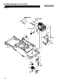
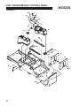
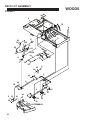
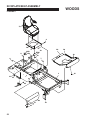
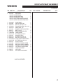
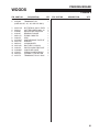
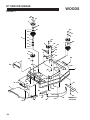
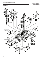
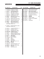
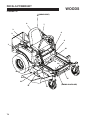
FRAME-ENGINE/CLUTCH ASSY
WOODS
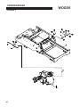
FIGURE 1
KAW ENGINE
ONLY
B & S ENGINE
ONLY
10
16
15
17
1
16
JUMPER HARNESS
27
26
3
13
27
21
24
28
22
23
4
29
2
11
18
8
31
5
32
19
14 30
7
12
9
20
25
44
6
10
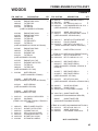
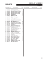
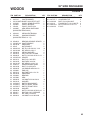
FRAME-ENGINE/CLUTCH ASSY
WOODS
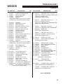
ITM PART NO.
FIGURE 1
DESCRIPTIONQTY
ITM PART NO.
DESCRIPTIONQTY
1
4164364
ENGINE-18HP KAW
4164365
ENGINE-20HP KAW
38666.W
FILTER-FUEL
4164537
FILTER-OIL
4164329
FILTER-AIR
(USED ON MODELS 9CZ2048K)
1
1
4164366
ENGINE-22HP KAW
4164367
ENGINE-24HP KAW
38666.W
FILTER-FUEL
4164630
FILTER-AIR
4164631
FILTER-SAFETY
4164537
FILTER-OIL
(USED ON MODELS CZ2252K & CZ2461K)
1
1
4163987
ENGINE-23HP B&S
38666.W
FILTER-FUEL
4164152
ELEMENT-AIR
4164153
FILTER-OIL
(USED ON MODEL CZ2361B)
1
2
4163705
ENGINE- KAI 17HP
4163715
ELEMENT-AIR FILTER
2722214
FILTER-OIL
38666.W
FILTER-FUEL
(USED ON MODEL CZ1736K)
1
4164386
1
4164385
MUFFLER -KAW
(USED ON MODELS CZ2252K & CZ2461K)
1
25 64123-55
BLT-HEX 5/16-18X3
1
(USED ON MODEL CZ2461B & CZ2461K ONLY)
4163913
MUFFLER-B&S
(USED ON MODEL CZ2361B)
1
4149239
MUFFLER-KAW
(USED ON MODEL CZ1736K)
26 4164251
VAILVE-OIL DRAIN
27 88042-03
CLAMP-HOSE
28 4164252-001FITTING-3/8NP TO BARB
1
2
1
29 11061-7061 GASKET-MUFFLER
(AVAILABLE FROM KAWASAKI DEALER)
2
MUFFLER-KAW
(USED ON MODEL CZ2048K)
38304-03
2721331.7
64265-04
64164-12
64006-06
64205-001
4164049
BRG-FLANGED PLASTIC
WLDMT-CLUTCH STOP
LOCKNUT-M8-1.25
KEY-1/4X1/4X1 SQ END
LOCKWASHER-HEL 7/16
BLT-MET M8-1.25X20
S-FRAME W/ LABELS
4144116
CLUTCH-ENGINE PULLEY
48412-01
CLAMP
64197-005 BLT-TDFM 3/8-16X1-1/4
64006-02
LOCKWASHER-HELICAL 5/16
(USED ON MODEL CZ2361B ONLY)
1
1
4
1
16 64163-55
WSHR .328X.75X14 GA
1
17 64223-11
SCH CAPSCREW M8-1.25X16 1
(USED ON MODEL CZ2361B ONLY)
18 4144112.7 WLDMT-CLUTCH BRACKET
19 4163309
PULLEY-ENGINE
20 64123-78
BOLT-HEX 7/16-20X2-1/2
(USED ON 942299F, 942404F & 942405F)
1
1
1
21 69053-13
1
HOSE-HTDRO, 3/8X14"
(ITEMS 22-23 USED ON KAW ENGINES ONLY)
22 64266-02
NUT-FL LOCK M8-1.25
2
23 64263-002 BLT-FLG HD M6-1.0 X 16
6
3 64152-23
1/4-20X3/8 LG SP SCREW
2
4 38665.W
SOLENOID
1
(ITEMS 3 & 4 USED ON CZ2252K, CZ2361B, &
CZ2461K)
5
6
7
8
9
10
11
12
13
14
15
1
1
2
1
1
3
1
24 4164442.7 BRKT-MUFFLER LH
1
*4164443.7 BRKT-MUFFLER RH
1
(USED ON MODELS CZ2048K, CZ2252K, &
CZ2461K)
4118507.7 BRKT-MUFFLER LH
* 4118508.7 BRKT-MUFFLER RH
(USED ON MODEL CZ1736K)
1
1
806425
GASKET-MUFFLER
(AVAILABLE FROM B&S DEALER)
(ITEMS 30-32 USED ON KAWASAKI UNITS ONLY)
30 64123-16
BLT-HEX 3/8-16X1-1/4 4
31 64163-31
WSHR 25/64X1X12
2
32 64006-03
LOCKWSHR-3/8 HELICAL
4
* NOT ILLUSTRATED
45
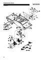
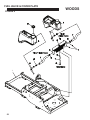
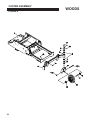
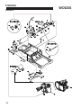
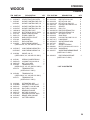
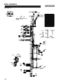
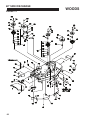
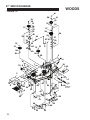
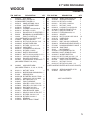
TRANSAXLE ASSY
WOODS
FIGURE 2
42
46
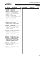
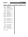
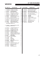
TRANSAXLE ASSY
WOODS
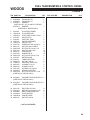
ITM PART NO.
1
2
3
4
5
6
7
8
9
10
11
12
13
14
15
16
17
18
19
20
21
22
23
FIGURE 2
DESCRIPTIONQTY
4164049
S-FRAME W/LABELS
1
4162973
SHAFT-PULLARM MOUNT
1
4163957.7 WLDMT-PULL ARM
2
4163819
ARM-CONTROL
2
4156464
AXLE-LH
1
(INCLUDES ITEMS 4, 25, 26, 27, 32, 39 & 40)
(USED ON 36", 48" AND 52" DECKS ONLY)
64163-29
WASHER
2
64123-68
BOLT-HEX 5/16-18X1
2
64025-02
NUT-HEX 5/16-18
2
64270-01
BOLT-MET, HEX M10-1.5x30 1
64123-54
BOLT, 5/16-18X3/4 HEX
2
64163-55
WASHER .328X.75X14 GA
6
4164128
SPRING-TENSION
1
64123-67
BLT-HEX 3/8-16 X 2
1
4128001
END CAP-24 X 7
1
64268-02
NUT-FL NYLON LOCK 5/16-18 10
2228016
PULLEY-IDLER PUMP
1
64163-31
WASHER, 25/64X1X12
12
64123-55
BLT-HEX 5/16-18X3
4
64229-03
LOCKNUT-NYLON 3/8-16
1
4156465
AXLE-RH
1
(INCLUDES ITEMS 4, 25, 26, 27, 32, 39 & 40)
(USED ON 36", 48" AND 52" DECKS ONLY)
4143636
BELT-TRANSAXLE
4163276
ROD-BATTERY CLAMP
108055.W BATTERY
(OBTAIN LOCALLY)
1
2
1
24 64123-88
BLT-HEX 3/8-16X2-3/4
4
25*4142045-06 FILTER-TRANSAXLE
2
26*4163819
SPRING-CONTROL ARM
2
27 4163820
ARM-BRAKE
2
28 64123-168 BLT-HEX 5/8-11X2-1/2
2
29 64163-93
WSHR-.635 X 1.12 X.062
4
30 85010N
ZERK, 1/4-28
4
31 64229-06
LOCKNUT, NYLON 5/8-11
2
32 4164048
KIT-FAN/PULLEY TRANSAXLE 2
(USED ON 36", 48", AND 52" DECKS ONLY)
4164129
KIT-FAN/PULLEY TRANSAXLE 2
(USED ON 61" DECKS ONLY)
ITM PART NO.
DESCRIPTIONQTY
33
4142752
TIRE-ASSY 20 X 8 - 10 4 PLY 2
4142752-01 20X8-10 4 PLY MULTI TRAC TIRE
4132433-03 WHEEL-10X7
(USED ON 48" DECKS ONLY)
4163731
TIRE-ASSY 20 X 6.50 - 10
2
4163731-01 WHEEL-10X5.375
4163731-02 TIRE-20X6.5-10 GRASSMASTER
(USED ON 36" DECKS ONLY)
4155841
TIRE-ASSY 20 X 10-10
2
4132433-01 TIRE-20X10-10 4PLY TURFMASTER
4155841-01 WHEEL-10X7
(USED ON 52" DECKS ONLY)
4163964
TIRE-ASSY 23X10.50-12
4158422-01 WHEEEL -4-HOLE W/VALVE
(USED ON 61" DECKS ONLY)
2
34 64187-03
WHEEL NUT 1/2-20
35 4133302
S-ASSY-IDLER ARM PUMP
(INCLUDES ITEMS 36-38)
8
1
36
37
38
39
40
41
42
43
44
45
46
2
1
1
2
1
3
1
2
2
4
1
4128004
BEARING-BALL 10X26X8
64144-40
SNAP RING-26MM INTERNAL
4128000
SEAL-16X26X7
64163-61
WASHER
4163299.7 TRAY-BATTERY
64197-022 BLT-TDFM 3/8-16X3/4
4163264-01 ADAPTER-90 #6 MAORB/#6 FORB
4163307
ASSY-EXPANSION TANK
4142808-01 CAP-HYDRO TANK
64268-03
NUT-FL NYLON LOCK 3/8-16
4163772
TRANSAXLE-LH (USED ON 61" DECK ONLY)
47 4163771
TRANSAXLE-RH (USED ON 61" DECK ONLY)
1
48* 4164227
CHARGE PUMP COVER KIT 1
(USED ON KAWASAKI ENGINES ONLY)
*4164228
CHARGE PUMP COVER KIT
(USED ON B & S ENGINES ONLY)
1
* NOT ILLUSTRATED
47
FUEL TANK/BUMPER & CONTROL PANEL
WOODS
FIGURE 3
8
34
6
19
12
7
14
5
11
10
22
9
13
35
2
30
3
16
17
15
29
16
17
30
32
28
15
26
33
24
25
31
18 / 27
23
4
21
21
18
48
FUEL TANK/BUMPER & CONTROL PANEL
WOODS
FIGURE 3
ITM PART NO.
DESCRIPTIONQTY
1 4164049
S-FRAME W/LABS
1
2 4142840-3 TANK-FUEL RH 1
3 4142841-3 TANK-FUEL LH
1
4 4163041.7 BUMPER
1
(USED ON 36", 42", 48" AND 52" DECKS)
4164221.7 BUMPER
1
(USED ON 61" DECKS ONLY)
5 4164526
S-CONTROL PANEL 6 128010-03 S-COVERED KEY
7 128010-01 S-KEY SWITCH NUT 5/8-32
8 2721505
SWITCH-PTO
9 4130320
CAP-FUEL TANK
10 2188178
SWITCH-RETAINER
11 128010.W SWITCH, KEY
12 64152-46
SCREW-SLT HH 10-24X1/2
13 64025-15
NUT-HEX #10-24 KEPS
14 64262-001 BLT-FLG HD 1/4-20 X 1/2
15 64123-50
BOLT-3/8-16X1 HEX
16 64006-03
WASHER-3/8
17 64163-69
WASHER-FLAT
18 64262-010 BLT-FLG HD 3/8-16 X 3/4
19 4136792
METER-HOUR
20*4144213
TUBE-FUEL FEED
21 64268-03
NUT-WLF 3/8-16
22 118020-17 CONTROL-THROTTLE
23 64229-02
LOCKNUT-5/16-18
24 48228-2A
CLAMP-3/4 CLIP
25 64123-54
BLT-HEX 5/16-18X3/4
26 4163901.7 WEIGHT-COUNTER
27 64262-018 BLT-FLG HD 3/8-16 X 1-3/4
(USED ON 61" DECKS ONLY)
ITM PART NO.
DESCRIPTIONQTY
1
1
1
1
2
1
1
2
2
4
10
10
10
4
1
2
4
1
2
2
2
1
4
28 4163895.7 CHANNEL-TANK SPACER, LH 1
(USED ON 61" DECKS ONLY)
29 4164022.7 CHANNEL-TANK SPACER, RH 1
(USED ON 61" DECKS ONLY)
30
31
32
33
34
35
64123-50
64229-03
4163880.7
4163905.7
108009-04
64025-04
BOLT-HEX 3/8-16X1
NUT-NYLON LOCK 3/16-18
BRKT-TANK MOUNTING
PLATE-WEIGHT
CABLE-CHOKE
NUT-HEX 3/8-24 8
8
2
1
1
1
* NOT ILLUSTRATED
49
FUEL VALVE & COVER PLATE
FIGURE 4
1
50
WOODS
FUEL VALVE & COVER PLATE
WOODS
ITM PART NO.
1
2
3
4
5
6
7
8
9
10
11
FIGURE 4
DESCRIPTIONQTY
4164049
S-FRAME W/LABS
4142840-1 TANK-FUEL RH
4142841-1 TANK-FUEL LH
64197-001 BLT-TDFM 5/16-18X3/4
4164803.7 COVER-FRAME, REAR
88042N
HOSE CLAMP
4162977-009 HOSE-1/4 FUEL LINE 24"
2188161
VALVE-TANK SELECTOR
4130320
CAP-FUEL TANK
4132325
GROMMET-FUEL TANK
4144213
TUBE-FUEL FEED
ITM PART NO.
DESCRIPTIONQTY
1
1
1
4
1
6
3
1
2
2
2
51
DECK LIFT ASSEMBLY
WOODS
FIGURE 5
28
30
1
32
9
25
10
16
8
34
24
10
20
22
33
21
29
27
19
16
21
11
6
19
11
7
11
31
14
2
15
5
14
14
18
26
23
4
14
6
3
16
17
2
13
15
14
14
12
12
11
11
CUTTERDECK
52
17
9
DECK LIFT ASSEMBLY
WOODS
ITM PART NO.
1
2
3
4
5
6
7
8
9
10
11
12
13
14
15
16
17
18
19
20
21
22
23
24
25
26
27
28
29
30
31
32
33
34
35
4164049
64205-060
4164565.7
4163894.7
4109960
64221-02
4163891.7
2188143
64123-50
85010N
64229-03
2182356.7
64205-029
64246-04
2188127
64163-65
64221-04
4143575.7
2183071-03
4163893.7
64168-2
64188-53
4139785
2720544
64123-67
4126611
4162904.7
64163-31
64175-05
64123-82
4159060
2720743
4159284
64163-29
64018-3
FIGURE 5
DESCRIPTIONQTY
S-FRAME W/LABS
BOLT-MET M12-1.75X50
WLDMT-DECKLIFT, FRONT
WLDMT-DECKLIFT REAR
WLDMT-DECK LIFT ROD
E-RING .250
BRKT-LIFT LINK GRIP
BOLT-HEX 3/8-16X1
ZERK, 1/4-28 STR
LOCKNUT-NYLON 3/8-16
BRACKET-SHAFT HANGER
BLT-MET M12X1.75X40
NUT-WHIZ M12-1.75
CHAIN-6.35 (.250) 5 LINKS
WASHER-.890X1.375X18GA
E-RING.875
BRKT-OUTER DECK LIFT
SPACER-15.88X10.32X24
LEVER-DECK LIFT
COTTER-HAIRPIN.08X1.19
PIN-CLEVIS 1/2X1.0
MAT-FOOT LIFT
SPRING-COMPRESSION
BLT-HEX 3/8-16X2
LABEL-H.O.C. OUTER, WLDMT-LVR STOP LATCH
WASHER
PUSHNUT-1/2 DIA
BOLT-HEX 3/8-16X2-1/2
ASSY, PIN & LANYARD
LBL-HT CUT INNER
ROD-LIFT STOP
WASHER-21/64X1X11GA
BLT-CRG 3/8-16X1
ITM PART NO.
DESCRIPTIONQTY
1
4
1
1
2
2
1
1
15
5
19
4
4
16
4
10
5
1
2
1
2
1
1
1
1
1
1
1
1
1
1
1
1
1
53
CASTER ASSEMBLY
WOODS
FIGURE 6
19
20
54
CASTER ASSEMBLY
WOODS
ITM PART NO.
FIGURE 6
DESCRIPTIONQTY
ITM PART NO.
DESCRIPTIONQTY
1
2
3
4
5
6
7
8
9
4164049
S-FRAME W/LABS
1
4162986
DUST COVER
2
85010N
ZERK-1/4-28
2
64025-20
NUT-HEX 3/4-16 SLOT U
2
64163-26
WASHER
2
48043-03C CUP-OUTER BEARING
4
48043-04C CONE-OUTER BEARING
4
48480.W
SEAL
2
4143675.7 WLDMT-CASTER
2
(USED ON 36", 42", 48" AND 52" DECKS ONLY)
2721306.7 WLDMT-CASTER (USED ON 61" DECKS ONLY)
10 64229-06
LOCKNUT-NYLON 5/8-11
2
(USED ON 36", 42", 48" AND 52" ONLY)
11 64123-212 BOLT-5/8-11X6.00
(USED ON 36", 42", 48" AND 52" ONLY)
2
12
13
2722231
SPACER-END
2722233
WHEEL-11"ASSY-LT TYPE
(USED ON 36", 42", 48" AND 52" ONLY)
2722228
WHEEL-ASSY 13x5.00-6 (USED ON 61" ONLY)
4
2
14
4162945.7 WLDMT-CSTR MOUNTING
(USED ON 48" & 52" ONLY)
4162974.7 WLDMT-CSTR MOUNTING
(USED ON 36" & 42" ONLY)
4163578.7 WLDMT-CSTR MOUNTING
(USED ON 61" ONLY)
1
15
16
17
64123-16
BLT-HEX 3/8-16X1-1/4
64229-03
LOCKNUT-NYLON 3/8-16
2722230-01 SPANNER-11" WHEEL
(USED ON 36", 42", 48" AND 52" ONLY)
2722230-02 SPANNER-13" WHEEL
(USED ON 61" ONLY)
8
8
2
2
1
1
18 304636
COTTER PIN
19 64123-215 BLT-HEX 3/4-10 X 7 1/2
(USED ON 61" ONLY)
2
2
20 64229-07
LOCKNUT-NYLON 3/4-10
(USED ON 61" ONLY)
2
55
KICKPLATE/SEAT ASSEMBLY
WOODS
FIGURE 7
2
4
6
5
13
8
5
3
12
24
20
18
23
19
22
8
9
7
1
11
12
9
12
10
17
21
56
16
14
15
KICKPLATE/SEAT ASSEMBLY
WOODS
ITM PART NO.
1
2
3
4
5
6
7
8
9
10
11
12
13
14
15
16
17
18
19
20
21
22
23
24
25
FIGURE 7
DESCRIPTIONQTY
4164049
S-FRAME W/LABS, 4163703
SEAT ASSY.
*4163703-01SEAT BACK
*4163703-02SEAT BOTTOM
*4163703-03ARM REST PAD
*4163703-04LH ARM MOUNTING BRKT
*4163703-05RH ARM MOUNTING BRKT
1
1
1
1
2
1
1
4163281.7
4124009
64268-02
33138-09
64144-30
4143354
64141-6
2722325
148082-20
64197-015
2188154
64123-16
64229-03
4164549.25
64197-005
4164776
4164480
4164479
4142266
64152-27
4129802
38061A
*970391
1
1
4
2
2
4
4
3
2
7
1
2
2
1
2
1
1
1
1
2
1
1
1
PLATE-SEAT
SWITCH-SEAT NO
NUT-NY LOCK 5/16-18
PIN-CLEVIS GRVD .38 X 1.31
SNAP RING .375
BUMPER, SEAT MOUNTING
NUT-5/16-18
RELAY-40AMP SEALED
FUSE-20 AMP
BLT-TDFM 10-32X1/2
MODULE-DELAY
BLT-HEX 3/8-16X1-1/4
NUT-NYL LOCK 3/8-16
PLATE-FRONT REMOVABLE
BLT-TDFM 3/8-16X1-1/4
S-FOOT PLATE
MAT-FOOT PLATE UPPER
MAT-FOOT PLATE LOWER
CONNECTOR-12V RECEPT
1/4-20X5/8 LG SP SCREW
TUBE-DOCUMENT
CAP-VINYL
KIT-LIGHT ACCESSORY
ITM PART NO.
DESCRIPTIONQTY
* NOT ILLUSTRATED
57
STEERING
FIGURE 8
58
WOODS
STEERING
WOODS
ITM PART NO.
1 4144705
2 4156297.7
3 4156295
*4156294
4
5
6
7
8
9
10
11
12
13
FIGURE 8
DESCRIPTIONQTY
GRIP-HANDLE
LEVER-TRACTION CNTRL
WLDMT-CONTROL BAR, RH
WLDMT-CONTROL BAR, LH
2
2
1
1
4143673.7 WLDMT-CONTROL BOX RH
4143674.7 WLDMT-CONTROL BOX LH
108208.W SWITCH DBL POLE
64197-015 BLT-TDFM 10-32X1/2 TORX
4127142
BSHG-CONTROL ARM
64221-03
E-RING 19MM/.750
4143676
BAR-CONTROL PIVOT
2721246
DAMPENER
4143571
ROD-CONTROL
4144525
ROD-PARKING BRAKE
(USED ON 36", 42", 48" AND 52" ONLY)
1
1
2
4
5
6
1
2
2
2
14 4155661.7
*4155660.7
LINK-PARKING BRAKE RH
LINK-PARKING BRAKE LH
1
1
15 4145589
SWIVEL-3/8-16
(USED ON 36", 42', 48" AND 52" ONLY)
2
16
17
18
19
4155481
SPRING-COMPRESSION
64268-03
LOCKNUT-NYLON 3/8-16
64025-05
NUT-3/8-16 HEX
4156465
TRANSAXLE-RH
(USED ON 36", 42', 48", AND 52" ONLY)
4163772
TRANSAXLE-RH
(USED ON 61" ONLY)
2
2
2
1
20 4156464
TRANSAXLE-LH
(USED ON 36", 42', 48" AND 52" ONLY)
4163771
TRANSAXLE-LH
(USED ON 61" ONLY)
1
21
22
23
24
25
26
27
28
29
1
1
2
2
2
2
2
1
2
4164049
4146988.7
64229-01
64123-89
4146187
64025-33
4145106
4155483.7
64168-2
S-FRAME W/LABS
BRKT-CNTRL BAR SUPT
LOCKNUT-1/4-20 NYLON
BOLT-HEX 1/4-20X3/4
BEARING-FLANGE
NUT-HEX 5/16-24 LH
SPACER-CONTROL ROD
BRAKE, ARM LINKAGE
COTTER-HAIRPIN
ITM PART NO.
30
31
32
33
34
35
36
37
38
39
40
41
42
43
44
45
46
47
48
DESCRIPTIONQTY
64123-69
BOLT-5/16-18X1-1/2 HEX
64123-68
BOLT-HEX 5/16-18X1
64123-50
BLT-HEX 3/8-16X1
64123-105 BLT-HEX 1/4-20X1-5/8
64237-05
LOCKNUT-NYLON M8-1.25
4133156
SPACER
64061-25
ROLL PIN
4143595-01 ROD END-FEMALE RH
4143595-02 ROD END-FEMALE LH
64025-03
NUT-HEX 5/16-24
64144-30
SNAP RING
64229-02
LOCKNUT-NYLON 5/16-18
4147116.7 LINK-BRAKE
4155482.7 WLDMT-BRAKE ARM
4147196
SPACER
41-010
SPRING-TENSION
64268-01
NUT-FL NYLON LOCK 1/4-20
64251-002 WASHER-M6
4164075
WLDMT-ROD PARKING BRAKE
(USED ON 61" ONLY)
49 4164024
ROD-PARKING BRAKE
(USED ON 61" ONLY)
2
2
4
2
4
2
2
2
2
2
2
4
1
1
1
1
2
2
2
2
* NOT ILLUSTRATED
59
PARKING BRAKE
WOODS
FIGURE 9
2
17
60
PARKING BRAKE
WOODS
ITM PART NO.
FIGURE 9
DESCRIPTIONQTY
1 4164049
S-FRAME W/LABST
2 4156464
TRANSAXLE, RH
(USED ON 36", 42", 48", AND 52" ONLY)
1
1
3
4
5
6
7
8
9
10
11
12
13
14
15
16
17
2
2
2
1
1
1
1
1
1
1
1
2
2
2
1
64197-015
64168-2
4148697
4146187
64221-03
2188155
4163060.7
64163-34
64006-01
64123-89
2188156
4148698.7
2720977
64229-01
4163772
BLT-TDFM 10-32X1/2 TORX
COTTER-HAIRPIN.08X1.19
ROD-BYPASS CONTROL
BEARING-FLANGE
E-RING 19MM/.750
GRIP
HANDLE-BRAKE FASTCAT
WASHER
LOCKWASHER
BOLT-HEX 1/4-20X3/4
SWITCH-NONO DBL POLE
LINK-DUMP VALVE
SPRING-COMPRESSION
LOCKNUT-1/4-20 NYLON
TRANSAXLE, RH 61" ONLY
ITM PART NO.
DESCRIPTIONQTY
61
WIRE HARNESS
WOODS
FIGURE 10
1
2
20
2.0 EXP
15
3
11
ELECTRIC
CLUTCH
4
STARTER
GROUND
17
YB
16
B
14 GA
12.0 EXP
5.0 EXP
85
85
30
NC
86
87A
NC
BLADES &
TRACTION
RELAY
B B
86
87A
STARTER
RELAY
12
BR
Y
BR
30
BATTERY
RW
TO ENGINE BLOCK
(GROUND)
BATTERY
W W
87
NO
O O
85
86
87A
NC
DELAY
RELAY
WIRE COLORS
W WHITE
W
YBWB WHITE W/ BLACK STRIPE
G P PURPLE
P O ORANGE
OB ORANGE W/ BLACK STRIPE
PO PURPLE W/ ORANGE STRIPE
OP ORANGE W/ PURPLE STRIPE
DB DARK BLUE
B BLACK
G GREEN
R RED
Y YELLOW
YB YELLOW W/ BLACK STRIPE
RW RED W/ WHITE STRIPE
GY GREEN W/ YELLOW STRIPE
BR BROWN
BRY BROWN W/ YELLOW STRIPE
YB
87
NO
8
BRY
BR
B B
B B
87
NO
8
8
2.0 EXP
14 GA
14 GA
B
16
P
R
TO SOLENOID (2)
W
G
(RED)
MAGNETO
STARTER SOL
OIL PRESS
CHARGING
B
DB
SOLENOID
ENGINE
B B
30
6
3
(RED)
(BLACK)
9
16
P P
14 GA
14 GA
7
5.0 EXP
14 GA
14 GA
SWITCH
KEY
Y
OFF
M+G
RUN
B+L
START B+L+S
W W P
O
14 GA
14 GA
B B
BD
R
14 GA
O
O
O
BO
14 GA
7.0 EXP
10
14 GA.
SWITCH
CLUTCH
O
G
HOUR
METER
MAGNETO
6.0 EXP
CARB
SOLENOID
5
B
2.0 EXP
PACKARD
#02962793
VOLTAGE
REGULATOR
P
P
14 GA
14 GA
G
12V
ADAPTER
SWITCH
TRACTION
CONTROL
PO
OB
NO
B
B
NC
13
O O
TO SOLENOID (3) Y
W
B
19
WB
4
O O
2.0 EXP
GY
2.0 EXP
PO
B WB
OP
WB
NO
NC
13
2.0 EXP.
2.0 EXP
SWITCH
TRACTION
CONTROL
BR
W
14
WB
OP
NO
NO
62
SWITCH
BRAKE
SWITCH
SEAT
21
18
TO SOLENOID (1)
14 GA
14 GA
R R
2
ENGINE BLOCK
(GROUND)
14 GA
6.0 EXP
FUSES
7.0 EXP
A B C D E F GY
RW
B
B
BRY
DELAY
MODULE
TO SOLENOID (4)
WIRE HARNESS
WOODS
ITM PART NO.
FIGURE 10
DESCRIPTIONQTY
1
2
3
4
5
6
4154880
HARNESS-MAIN WIRE
148082-20 FUSE 20 AMP
30-419
CABLE-BATT 4 GA BLK 29"
4124009
SWITCH-SEAT NO
4136792
METER-HOUR
30-180
CABLE-BATT 4 GA RED 29"
(USED ON 22HP, 23HP, AND 24HP ONLY)
1
2
1
1
1
1
2722227-02 CABLE-BATTERY W/COND
(USED ON 18HP AND 20HP ONLY)
1
7
8
9
10
11
12
13
14
15
128010.W SWITCH, KEY
2722325
RELAY-40AMP SEALED
2188154
MODULE-DELAY
2721505
SWITCH-PTO
4144116
CLUTCH-ELECTRICAL
30-184
COVER-POS TERMINAL
108208.W SWITCH DBL POLE
2188156
SWITCH-NONO DBL POLE
38665.W
SOLENOID
(USED ON 17HP, 22HP, 23HP, AND 24HP
ONLY)
1
3
1
1
1
1
2
1
1
16 2308095
COVER-TERMINAL
17 108061-04 CABLE-BATTERY 20 RED
(USED ON 22HP, 23HP, AND 24HP ONLY)
3
1
18 2188225
WIRE-GROUND
(USED ON 22HP, 23HP, AND 24HP ONLY)
1
ITM PART NO.
DESCRIPTIONQTY
19 2188224
HARNESS-JUMPER
1
(USED ON 17HP, 22HP AND 24HP ENGINES
ONLY)
2722013
HARNESS-JUMPER
(USED ON 23HP B&S ENGINES ONLY)
1
4164496
HARNESS-JUMPER
(USED ON 20HP ENGINES ONLY)
20 2720949
ASSY-CLUTCH WIRE
21 158136
WIRE-SEAT SWITCH
22*56-081-36 SLEEVING, ID 0.77 NYLON 1
1
1
1
* NOT ILLUSTRATED
63
36" SIDE DISCHARGE
WOODS
FIGURE 11
15
16
17
5
36
15
14
10
16
9
4
5
11
24
10
25
6
12
8
6
4
27
28
29
32
18
36
14
26
13
7
30
43
19
38
42
17
42
43
46
44
1
44
31
21
21
41
21
45
21
23
2
20
21
37
64
39
34
33
37
31
37
40
16
37
35
22
TORQUE TO
70 FT-LBS
3
36" SIDE DISCHARGE
WOODS
ITM PART NO.
1
2
3
4
5
6
7
FIGURE 11
DESCRIPTIONQTY
4152858
S-36 DECK W/LABELS
4147115
CHUTE-RUBBER
112111-02KT2BLADE 18.00 OFFST HLFT
4115850
S-ASSY SPINDLE OUTER
4144947
PULLEY-SPINDLE
128169
PULLEY, IDLER 5.50
4146065
ARM, DECK IDLER ASSY
(INCLUDES ITEMS 28-30)
1
1
2
2
2
2
1
8 2308133
SPRING-EXTENSION
9 2721096
HOUSING-SPINDLE
(INCLUDES ITEMS 10 - 13)
1
2
10
11
12
13
14
15
16
17
18
19
20
21
22
23
24
25
26
27
28
29
30
31
32
33
34
35
36
37
38
39
40
4
2
2
2
12
2
4
2
1
1
1
7
2
2
1
1
1
1
1
2
1
14
4
1
1
1
4
8
1
2
2
38348-01
BEARING-SPINDLE SEALED
2183070-02 SHAFT-SPINDLE
64144-38
SNAP RING
38315
NUT-SPINDLE
64262-012 BLT-FLG HD 3/8-16 X 1-1/4
64123-208 BLT-HEX 5/8-18X1.5
64209-03
SPRING WASHER
64164-12
KEY-1/4X1/4X1 SQ END
64268-05
NUT-FL NYLON LOCK 1/2-13
4152578-01 SPACER
64123-31
BOLT-1/2-13X3 HEX
64123-50
BOLT-HEX 3/8-16X1
64123-187 BLT-HEX 5/8-18 X 3 3/4
4118314
SPACER-BLADE 16MM
64123-90
BOLT, 1/2-20X2 HEX
64006-05
LOCKWSHR-HELICAL 1/2
4128002
END CAP
64270-01
BOLT-MET M10-1.5 X 30
64144-40
SNAP RING
4128004
BEARING
4127999
SEAL
64229-03
LOCKNUT-NYLON 3/8-16
64163-19
WASHER
4115864.7 BAFFLE-DISCHARGE
4134343.7 BAFFLE-RIGHT FRONT
4147035.7 BAFFLE-FRONT DECK
64163-84
WASHER
64268-03
NUT-FL NYLON LOCK 3/8-16
64018-3
BOLT-3/8-16X1 CARRIAGE
64018-2
BLT-CRG 1/4-20X3/4
64229-01
LOCKNUT-1/4-20 NYLON
ITM PART NO.
41
42
43
44
45
46
4149017.7
4147757.7
64139-08
64141-6
64262-013
64144-36
DESCRIPTIONQTY
HINGE-CHUTE_RUBBER
COVER-BELT 36
BOLT-5/16-18X3/4 WLF
FLANGE NUT, 5/16-18 NC ZP
BLT-FLG HD 3/8-16 X 1-1/2
E-CLIP
1
2
4
4
2
1
65
48" SIDE DISCHARGE
WOODS
FIGURE 12
57
66
48" SIDE DISCHARGE
WOODS
ITM PART NO.
1
2
3
4
5
6
7
8
9
10
11
12
13
14
15
16
17
FIGURE 12
DESCRIPTIONQTY
4146864
S-48 DECK W/LABELS
4146596.25 GUARD-LH 48" DECK
4146595.25 GUARD-RH 48" DECK
4147115
CHUTE-RUBBER
64123-50
BOLT-HEX 3/8-16X1
64018-11
BOLT-CRG 1/2-13X3LG
64229-03
LOCKNUT-NYLON 3/8-16
64205-029 BLT-MET M12X1.75X40
64246-04
NUT-WHIZ M12-1.75
2188127
CHAIN-6.35 (.250) 5 LINKS
4144947
PULLEY-SPINDLE
112111-01KTBLADE 16.25 OFFST HLFT
64262-012 BLT-FLG HD 3/8-16 X 1-1/4
64209-03
SPRING WASHER.67 ID
64164-12
KEY-1/4X1/4X1 SQ END
128169
PULLEY, IDLER 5.50
4147896
ARM-DECK IDLER ASSY
(INCLUDES ITEMS 30-32)
1
1
1
1
9
2
25
8
16
4
3
3
18
6
3
3
1
18 4115850
S-ASSY SPINDLE OUTER
(INCLUDES ITEMS 25-29)
3
19
20
21
22
23
24
25
26
27
28
29
30
31
32
33
34
35
36
37
38
39
40
1
1
3
3
3
1
6
3
3
3
3
1
2
1
1
1
1
2
2
1
1
1
64006-05
64123-05
4118314
64123-187
64123-208
2308133
38348-01
2721096
64144-38
38315
2183070-02
4127999
4128004
64144-40
64270-01
4128002
4152578-01
64262-013
64268-05
64018-30
2721512
2720685
LOCKWSHR-HELICAL 1/2
BLT-HEX 1/2-20X1-1/2
SPACER-BLADE 16MM
BLT-HEX 5/8-18 X 3 3/4
BLT-HEX 5/8-18X1.5
SPRING-EXTENSION
BEARING-SPINDLE SEALED
HOUSING-SPINDLE 6 HOLE
SNAP RING
NUT-SPINDLE
SHAFT-SPINDLE
SEAL
BEARING
SNAP RING
BOLT-MET M10-1.5 X 30
END CAP
SPACER
BLT-FLG HD 3/8-16 X 1-1/2
NUT-FL NY LOCK 1/2-13
BOLT-CARRIAGE
ROLLER
SPACER-ROLLER
ITM PART NO.
41
42
43
44
45
46
47
48
49
50
51
52
53
54
55
56
57
4120175.7
4134336.7
4134342.7
4120208.7
64018-3
64268-03
64018-2
64229-01
64163-84
64163-19
38524.W
4149017.7
64144-36
4163332
64141-13
64123-31
4163514.7
DESCRIPTIONQTY
BAFFLE-FRONT LH
1
BAFFLE-FRONT CENTER
1
BAFFLE-RIGHT FRONT
1
BAFFLE-DISCHARGE
1
BOLT-3/8-16X1 CARRIAGE
1
NUT-FL NYLON LOCK 3/8-16 10
BLT-CRG 1/4-20X3/4
4
LOCKNUT-1/4-20 NYLON
4
WASHER
6
WASHER
A/R
KNOB-4 PRONG
2
HINGE-CHUTE_RUBBER
1
E-CLIP
1
ROLLER-ANTI SCALP
2
NUT WLF 1/2-13
4
BLT-HEX 1/2-13X3
2
GUIDE-BELT
1
67
52" SIDE DISCHARGE
FIGURE 13
68
WOODS
52" SIDE DISCHARGE
WOODS
ITM PART NO.
1
2
3
4
5
6
7
8
9
10
11
12
13
14
15
16
17
FIGURE 13
DESCRIPTIONQTY
4153817
S-52 DECK W/LABELS
4143552.25 GUARD-LH 52" DECK
4143553.25 GUARD-RH 52" DECK
4147115
CHUTE-RUBBER ASSY
64123-50
BOLT-HEX 3/8-16X1
64018-11
BOLT-CRG 1/2-13X3LG
64229-03
LOCKNUT-NYLON 3/8-16
64205-029 BLT-MET M12X1.75X40
64246-04
NUT-WHIZ M12-1.75
2188127
CHAIN-6.35 (.250) 5 LINKS
4144947
PULLEY-SPINDLE
112111-02 BLADE 18.00 OFFST HLFT
64262-012 BLT-FLG HD 3/8-16 X 1-1/4
64209-03
SPRING WASHER.67 ID
64164-12
KEY-1/4X1/4X1 SQ END
128169
PULLEY, IDLER 5.50
4147896
ARM-DECK IDLER ASSY
(INCLUDES ITEMS 30-32)
1
1
1
1
9
2
24
8
16
4
3
3
18
6
3
3
1
18 4115850
S-ASSY SPINDLE OUTER
(INCLUDES ITEMS 25-29)
3
19
20
21
22
23
24
25
26
27
28
29
30
31
32
33
34
35
36
37
38
39
40
1
1
3
3
3
1
6
3
3
3
3
1
2
1
1
1
1
2
2
3
3
3
64006-05
64123-90
4118314
64123-187
64123-208
2308133
38348-01
2721096
64144-38
38315
2183070-02
4127999
4128004
64144-40
64270-01
4128002
4152578-01
64262-013
64268-05
64018-30
2721512
2720685
LOCKWSHR-HELICAL 1/2
BLT-HEX 1/2-20 X 2
SPACER-BLADE 16MM
BLT-HEX 5/8-18 X 3 3/4
BLT-HEX 5/8-18X1.5
SPRING-EXTENSION
BEARING-SPINDLE SEALED
HOUSING-SPINDLE 6 HOLE
SNAP RING
NUT-SPINDLE
SHAFT-SPINDLE
SEAL
BEARING
SNAP RING
BOLT-MET M10-1.5 X 30
END CAP
SPACER
BLT-FLG HD 3/8-16 X 1-1/2
NUT-FL NY LOCK 1/2-13
BOLT-CRG 3/8-16 X 4-1/2
ROLLER
SPACER-ROLLER
ITM PART NO.
41
42
43
44
45
46
47
48
49
50
51
52
53
54
4118427.7
4134338.7
4134343.7
4115864.7
64018-3
64268-03
64018-2
64229-01
64163-84
64163-19
38524.W
4149017.7
64144-36
4163514.7
DESCRIPTIONQTY
BAFFLE-FRONT LH
1
BAFFLE-FRONT CENTER
1
BAFFLE-RIGHT FRONT
1
BAFFLE-DISCHARGE
1
BOLT-3/8-16X1 CARRIAGE
1
NUT-FL NYLON LOCK 3/8-16 10
BLT-CRG 1/4-20 X 3/4
4
LOCKNUT-1/4-20 NYLON
4
WASHER
6
WASHER
A/R
KNOB-4 PRONG
2
HINGE-CHUTE_RUBBER
1
E-CLIP
1
GUIDE-BELT
1
69
61" SIDE DISCHARGE
WOODS
FIGURE 14
40
19
18
11
70
27
55
41
66
17
25
15
54
38
30
29
4
57
58
62
44
21
11
34
57
59
6
3
38
39
35
43
53
7
65 20
45
53
7
45
35
35
37
69
45
16 47
40
53
47
47
9 13
35
35
56
5
61
46
46
49
53
42 48
53
53
48
53
7
12
TORQUE TO
70 FT. LBS
51
50
53
70
24
7
31
2
64
14
4
16
26
33
60
63
23 8
32
52
35
34
22
67 36
10
28
21
11
69
61" SIDE DISCHARGE
WOODS
ITM PART NO.
FIGURE 14
DESCRIPTIONQTY
1
2
3
4
5
6
7
8
9
10
11
12
13
14
15
16
17
18
19
20
21
22
23
24
4164130 S-61" DECK
4163809.25BELT COVER RH
4163808.25BELT COVER LH
38524.W KNOB-4 PRONG 3/8-16
4147399 CHUTE-RUBBER ASSY
64158-08 EYE BOLT
64229-03 LOCKNUT NYLON 3/8-16
64123-31 BLT-HEX 1/2-13X3
2721512 ROLLER-5X2.75 CENTERED
548138
BRG NDL.88 1.12 1.00 OPEN END
128169
PULLEY IDLER 5.50
112111-03KTBLADE 21.00 OFFST HLFT
2720685 SPACER-ROLLER
64262-012 BLT-FLG HD 3/8-16 X 1-1/4
4164094.7 WLDMT-IDLER ARM
64018-33 BLT-CRG 1/2-13 X 4-1/2
4163514.7 GUIDE-BELT
64006-05 LOCKWSHR-1/2 HELICAL
64123-90 BLT-HEX 1/2-20X2
4115864.7 BAFFLE-DISCHARGE
64268-05 NUT-FL NYLON LOCK 1/2-13
64164-12 1/4X1/4X1 SQ END KEY
4163332 ROLLER, ANTI-SCALP
4115849 S-ASSYSPNDL ZT200 CNTR
(INCLUDES ITEMS 57-60, & 62)
25
4164095 ASSY-IDLER ARM 1
(INCLUDES ITEMS 10, 15, 28, 41, 55, 66)
26
27
28
29
30
31
32
33
34
35
36
37
38
39
40
41
42
64141-13
64270-02
521438
64205-029
2188127
64246-04
4149197
4163804
4163802
64123-50
64229-02
4118314
64163-74
64018-30
64123-208
4128004
4134344.7
NUT-WLF 3/8-24
BOLT-HEX M10-1.5X30 ISOCL10.9
GREASE SEAL BLT-METRIC M12X1.75X40
CHAIN-6.35 (.250) 5 LINKS
NUT-WHIZ M12-1.75
PULLEY-SPINDLE
SPACER-1.015X1.75X1.50
SPACER-1.0X.516X1-15/16
BOLT-HEX 3/8-16X1
LOCKNUT-NYLON 5/18
SPACER-BLADE 16MM
WSHR-.516X2X.25THK PLT
BLT-CRG 3/8-16 X 4-1/2
BLT-HEX 5/8-18X1.5
BEARING
BAFFLE-RIGHT FRONT 1
1
1
2
1
1
28
2
5
2
3
3
5
18
1
2
1
1
1
1
2
3
2
3
4
1
1
4
4
8
3
3
2
12
1
3
2
4
3
1
1
ITM PART NO.
DESCRIPTIONQTY
43
64163-55 WSHR .328X.75X14 GA
1
44
4163586 SPRING-EXTENSION
1
45
64123-114 BLT-HEX 1/4-20X1
7
46
64018-2 BLT-CRG 1/4-20X3/4
4
47
64141-2 NUT-WLF 1/4-20
7
48
64229-01 LOCKNUT-1/4-20 NYLON
4
49
4134340.7 BAFFLE-FRONT CTR 61
1
50
4117663.7 BAFFLE-FRONT LH
1
51
4163441.7 EXTENSION-61IN, LH 1
52
4163014 SPACER
1
53
64268-03 NUT-FL NYLN LOCK 3/8-16 10
54
4163155 INNER RING
2
55
64144-40 SNAP RING
1
56
64018-3 BOLT-3/8-16X1 CARRIAGE 1
57
38348-01 BEARING-SPINDLE SEALED 6
58
2721096 HOUSING-SPINDLE 6 HOLE 3
59
64144-38 SNAP RING
3
60
38315
NUT-SPINDLE
3
61
4163440.7 EXTENSION-61IN, RH
1
62
2183070-01 SHAFT-SPINDLE LONG
3
63 4163030.7 WLDMT-IDLER PIN 1
64
64262-013 BLT-FLG HD 3/8-16 X 1-1/2 2
65
4149017.7 HINGE-CHUTE RUBBER
1
66
85010N
ZERK-1/4-28 STR SLF THRD 1
67
64141-6 NUT-WLF 5/16-18
1
68* 64123-217 BLT-HEX 3/8-16X4 - 1/4
1
(USED ON REAR CENTER ANTI-SCALP ROLLER)
69
70
64209-03 SPRING WASHER .67 ID
4128002 END CAP- 26X7
6
4
*NOT ILLUSTRATED
71
BELTS-CUTTERDECK
WOODS
FIGURE 15
5
2
3
4
72
BELTS-CUTTERDECK
WOODS
ITM PART NO.
1
2
3
4
5
4144212
4143733
4147095
4163569
4147716
FIGURE 15
DESCRIPTIONQTY
BELT-36" CUTTERDECK
BELT-52" CUTTERDECK
BELT-48" CUTTERDECK
BELT-61" CUTTERDECK
BELT-42" CUTTERDECK
ITM PART NO.
DESCRIPTIONQTY
1
1
1
1
1
73
DECALS-POWERUNIT
WOODS
FIGURE 16
5 (UNDER SEAT)
16
4
7
2
6
9
8
1
18
18
4
10
14
17
12
11
74
13
3
(UNDER FOOTPLATE)
DECALS-POWERUNIT
WOODS
ITM PART NO.
1
2
3
4
5
6
7
8
9
10
11
12
13
14
15
16
17
18
4144768
2000570
4164525
4152340
2000590
2000701
2000700
4126804
4147617
4164279
4164269
2720743
2000577
4126611
4146936
4133980
4152003
4164835
4164831
4164832
4164833
4164834
FIGURE 16
DESCRIPTIONQTY
LABEL-CONTROL PANEL
LABEL-WARN FUEL PICT.
LABEL-INFORMATION
LABEL-WOODS
LABEL-WARN BATTERY
LABEL-LH TRACTION
LABEL-RH TRACTION
LABEL-PARKING BRAKE
LABEL-FUEL TANK VALVE
LABEL-WARNING
LABEL-DANGER/WARNING
LABEL-HOC INNER
LABEL, WARNING
LABEL-HOC OUTER
LABEL-MANUAL LOCATION
LABEL-MAINTENANCE
LABEL-WOODS CZ
LABEL-CZ1736K
LABEL-CZ2048K
LABEL-CZ2252K
LABEL-CZ2361B
LABEL-CZ2461K
ITM PART NO.
DESCRIPTIONQTY
1
2
1
2
1
1
1
1
1
1
2
1
3
1
1
2
1
75
LIMITED WARRANTY
(Mow’n Machine Zero-Turn Mowers and Woods Boundary Utility Vehicles)
TM
TM
Please Enter Information Below and Save For Future Reference.
Date Purchased: __________________________
From (Dealer):______________________________________
Model Number: __________________________
Serial Number: _____________________________________
WHAT IS COVERED:
Woods Equipment Company (“WOODS”) warrants Mow’n MachineTM zero-turn mowers and attachments and Woods BoundaryTM utility
vehicles, accessories and attachments to be free from defect in material and workmanship for the warranty periods listed below.
FOR HOW LONG:
Mow’n Machine Model #CZ1736K, CZ1948K, CZ1952K, CZ2361, ME1952K, ME2661B, MZ2552K, MZ2561K, MZ2761, MZ3761K,
MZ3772K, MZ2661KL & attachments are warranted for two (2) years from the date of delivery to the original purchaser or 2000 hours of
operation, whichever occurs first. Purchaser may opt for a warranty of five (5) years from the date of delivery to the original purchaser or 500
hours of operation, whichever occurs first. The dealer must specify the special warranty term on the original, dated bill of sale and a copy must
be provided with all warranty claims. Mow’n Machine model numbers CZR2242B and CZR2652B are warranted for residential use for three (3)
years from the date of delivery to the original purchaser or for commercial use for 90 days from the date of delivery to the original purchaser..
Mow’n Machine Model #FE21B, FZ21D, FZ23B, FZ25D, FZ28K & attachments are warranted for two (2) years from the date of delivery to the
original purchaser or 2000 hours of operation, whichever occurs first.
In addition, Mow’n Machine ME and MZ Series Models, serial number XXXXXXXX300 and above, have a Limited Lifetime Warranty on deck,
deck cradle, and engine deck for the life of the machine to the original retail purchaser.
Woods Boundary utility vehicle Model #MAV350, MAV480, MAV4x4, accessories & attachments are warranted for two (2) years from the date
of delivery to the original purchaser.
IMPLIED WARRANTIES OF MERCHANTABILITY AND/OR FITNESS FOR A PARTICULAR PURPOSE ARE LIMITED IN DURATION
TO THE DURATION OF THE WRITTEN WARRANTY PERIODS LISTED ABOVE. Some states do not allow limitations on how long an
implied warranty lasts, so the above limitation may not apply to you.
WHO IS COVERED:
This Warranty is extended solely to the original purchaser of the product. Should the original purchaser sell or otherwise transfer the product to a
third party, this Warranty does not transfer to the third party purchaser in any way. There are no third party beneficiaries of this Warranty.
WHAT IS NOT COVERED:
This Warranty does not cover normal wear or tear, or normal maintenance items, or any damage, failure or loss caused by:
1. Improper operation, improper maintenance, misuse, or an accident;
2. Any modification or repair by someone other than WOODS, a WOODS’ authorized dealer or distributor, and/or a WOODS’
authorized service center; or
3. Repairs made with parts other than those obtained through WOODS.
WOODS makes no warranty, express or implied, with respect to engines, batteries, tires or other parts or accessories with respect to which the
manufacturer provides a separate warranty.
WHAT WOODS WILL DO TO CORRECT PROBLEMS:
WOODS’ obligation under this Warranty is limited to, at WOODS’ option, the repair or replacement, free of charge, of the product if the product
is defective or in noncompliance with this Warranty. The product must be returned to WOODS with proof of purchase within thirty (30) days
after such defect or noncompliance is discovered or should have been discovered, routed through the dealer and distributor from whom the
purchase was made, transportation charges prepaid. WOODS shall complete such repair or replacement within a reasonable time after WOODS
receives the product.
OTHER LIMITATIONS:
WOODS shall not be liable for any incidental or consequential losses, damages or expenses, arising directly or indirectly from the
product, whether such claim is based upon breach of contract, breach of warranty, negligence, strict liability in tort or any other legal
theory. Without limiting the foregoing, WOODS shall not be liable for any damages relating to (i) lost profits, business, revenues or goodwill;
(ii) any expense or loss incurred for labor, supplies, substitute machinery or rental; or (iii) any other type of damage to property or economic loss.
Some states do not allow the exclusion or limitation of incidental or consequential damages, so the above limitations may not apply to you.
No agent, representative, dealer, distributor, service person, salesperson, or employee of any company, including without limitation, WOODS, its
authorized dealers, distributors, and service centers, is authorized to alter, modify, or enlarge this Warranty.
HOW STATE LAW APPLIES:
This Warranty gives you specific legal rights, and you may also have other rights which vary from state to state.
QUESTIONS:
Answers to any questions regarding warranty service and locations may be obtained by contacting:
Woods Equipment
Company
2606 South Illinois Route 2
Post Office Box 1000
Oregon, Illinois 61061
800-319-6637 tel
800-399-6637 fax
www.WoodsEquipment.com
F-8045 MM & Boundary (Rev. 12/1/2008)
LIMITED WARRANTY
(Mow’n Machine Zero-Turn Mower and
Woods Boundary Utility Vehicle Replacement Parts)
TM
TM
Woods Equipment Company (“WOODS”) warrants replacement parts for Mow’n Machine zero-turn
mowers and attachments and Woods Boundary utility vehicles, accessories and attachments to be free
from defect in material and workmanship for a period of ninety (90) days from the date of delivery of the
product to the original purchaser.
TM
TM
IMPLIED WARRANTIES OF MERCHANTABILITY AND/OR FITNESS FOR A PARTICULAR
PURPOSE ARE LIMITED IN DURATION TO A PERIOD OF NINETY (90) DAYS FROM THE
DATE OF DELIVERY OF THE PRODUCT TO THE ORIGINAL PURCHASER. Some states do not
allow limitations on how long an implied warranty lasts, so the above limitation may not apply to you.
This Warranty is extended solely to the original purchaser of the product. Should the original purchaser
sell or otherwise transfer the product to a third party, this Warranty does not transfer to the third party
purchaser in any way. There are no third party beneficiaries of this Warranty.
This Warranty does not cover normal wear or tear, or normal maintenance items, or any damage, failure
or loss caused by improper operation, improper maintenance, misuse, or an accident.
WOODS’ obligation under this Warranty is limited to, at WOODS’ option, the repair or replacement,
free of charge, of the product if the product is defective or in noncompliance with this Warranty. The
product must be returned to WOODS with proof of purchase within thirty (30) days after such
defect or noncompliance is discovered or should have been discovered, routed through the dealer
and distributor from whom the purchase was made, transportation charges prepaid. WOODS
shall complete such repair or replacement within a reasonable time after WOODS receives the product.
WOODS shall not be liable for any incidental or consequential losses, damages or expenses,
arising directly or indirectly from the product, whether such claim is based upon breach of
contract, breach of warranty, negligence, strict liability in tort or any other legal theory. Without
limiting the foregoing, WOODS shall not be liable for any damages relating to (i) lost profits, business,
revenues or goodwill; (ii) any expense or loss incurred for labor, supplies, substitute machinery or rental;
or (iii) any other type of damage to property or economic loss. Some states do not allow the exclusion or
limitation of incidental or consequential damages, so the above limitations may not apply to you.
No agent, representative, dealer, distributor, service person, salesperson, or employee of any company,
including without limitation, WOODS, its authorized dealers, distributors, and service centers, is
authorized to alter, modify, or enlarge this Warranty.
This Warranty gives you specific legal rights, and you may also have other rights which may vary from
state to state.
Answers to any questions regarding warranty service and locations may be obtained by contacting:
Woods Equipment
Company
2606 South Illinois Route 2
Post Office Box 1000
Oregon, Illinois 61061
800-319-6637 tel
800-399-6637 fax
www.WoodsEquipment.com
F-8495 MM & Boundary Repair Parts (Rev. 2/15/2006)
Woods Equipment
Company
2606 South Illinois Route 2
Post Office Box 1000
Oregon, Illinois 61061
800-319-6637 tel
800-399-6637 fax
www.WoodsEquipment.com
©2008 Woods Equipment Company. All rights reserved. WOODS, the Woods logo, and “Tested. Proven. Unbeatable.” are trademarks
of Woods Equipment Company. All other trademarks, trade names, or service marks not owned by Woods Equipment Company that
appear in this manual are the property of their respective companies or mark holders. Specifications subject to change without notice.