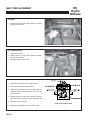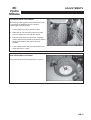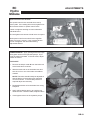
1
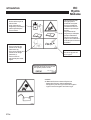
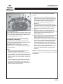
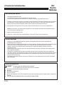
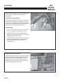
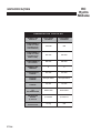
36” SIDE DISCHARGE HYDRO MIDSIZE
Rev.A 12-2007
MAN 4163233-PT
933304
16HP KAW ES EU
Parts Manual 4163232
OPERATOR MANUAL
933303
16HP KAW ES EU
OPERADOR MANUAL
36” REAR DISCHARGE HYDRO MIDSIZE
EC
Hydro
Midsize
CONTENTS
IMPORTANT MESSAGE
Thank you for purchasing this CGC Inc. product. You have purchased a world class mowing product, one of the best
designed and built anywhere.
This machine comes with an Operation and Safety Manual and a separate Setup, Parts and Maintenance Manual.
The useful life and good service you receive from this machine depends to a large extent on how well you read
and understand these manuals. Treat your machine properly, lubricate and adjust it as instructed, and it will give
you many years of reliable service.
Your safe use of this CGC Inc. product is one of our prime design objectives. Many safety features are built in, but
we also rely on your good sense and care to achieve accident-free operation. For best protection, study the manuals
thoroughly. Learn the proper operation of all controls. Observe all safety precautions. Follow all instructions and
warnings completely. Do not remove or defeat any safety features. Make sure those who operate this machine are
as well informed and careful in its use as you are.
See a CGC Inc. dealer for any service or parts needed. CGC Inc. service ensures that you continue to receive the
best results possible from CGC Inc.’ products. You can trust CGC Inc. replacement parts because they are
manufactured with the same high precision and quality as the original parts.
CGC Inc. designs and builds its equipment to serve many years in a safe and productive manner. For longest life,
use this machine only as directed in the manuals, keep it in good repair and follow safety warnings and instructions.
You'll always be glad you did.
Commercial Grounds Care Inc.
One Bob Cat Lane
Johnson Creek, WI 53038-0469
TABLE OF CONTENTS
PAGE
CONTENTS ................................................................................................................................................... 1
SAFETY ......................................................................................................................................................... 2
LABELS ....................................................................................................................................................... 3-5
GENERAL INSTRUCTIONS ...................................................................................................................... 6, 7
CONTROLS ............................................................................................................................................... 8, 9
MACHINE OPERATION .......................................................................................................................... 10-12
HEIGHT OF CUT .................................................................................................................................... 13-15
BELT REPLACEMENT ................................................................................................................................. 16
ADJUSTMENTS ...................................................................................................................................... 17-20
VIBRATION LEVEL ...................................................................................................................................... 21
SPECIFICATIONS ................................................................................................................................... 22-24
RANSOMES WARRANTY ..................................................................................................................... 25, 26
9 2007
GB-1
EC
Hydro
Midsize
SAFETY
NOTICE !!!
Unauthorized modifications may present extreme
safety hazards to operators and bystanders and
could also result in product damage.
Commercial Grounds Care Inc. strongly warns against,
rejects and disclaims any modifications, add-on
accessories or product alterations that are not
designed, developed, tested and approved by
Commercial Grounds Care Inc. Engineering
Department. Any Commercial Grounds Care Inc.
product that is altered, modified or changed in any
manner not specifically authorized after original manufacture–including the addition of “after-market” accessories or component parts not specifically approved
by Commercial Grounds Care Inc.–will result in the
Commercial Grounds Care Inc. Warranty being voided.
Any and all liability for personal injury and/or property
damage caused by any unauthorized modifications,
add-on accessories or products not approved by
Commercial Grounds Care Inc. will be considered the
responsibility of the individual(s) or company designing
and/or making such changes. Commercial Grounds
Care Inc. will vigorously pursue full indemnification
and costs from any party responsible for such
unauthorized post-manufacture modifications and/or
accessories should personal injury and/or property
damage result.
This symbol means:
ATTENTION!
BECOME ALERT!
Your safety and the safety of others is involved.
Signal word definitions:
The signal words below are used to identify levels of
hazard seriousness. These words appear in this
manual and on the safety labels attached to Textron
Golf, Turf & Specialty Products machines. For your
safety and the safety of others, read and follow the
information given with these signal words and/or the
symbol shown above.
DANGER indicates an imminently hazardous
situation which, if not avoided, WILL result in death
or serious injury.
WARNING indicates a potentially hazardous situation
which, if not avoided, COULD result in death or
serious injury.
CAUTION indicates a potentially hazardous situation
which, if not avoided, MAY result in minor or moderate
injury. It may also be used to alert against unsafe
practices or property damage.
CAUTION used without the safety alert symbol
indicates a potentially hazardous situation which, if
not avoided, MAY result in property damage
MODEL NUMBER: This number appears on sales
literature, technical manuals and price lists.
SERIAL NUMBER: This number appears only on
your mower. It contains the model number followed
consecutively by the serial number. Use this number
when ordering parts or seeking warranty information.
SERIAL TAG
GB-2
EC
Hydro
Midsize
LABELS
009034760
Noise Emission
- Complies with the provisions of the following
European directives and amendments and the
regulations transposing it into national law:
Machinery Safety Directive: .......... 98/37/EEC
EMC Directive: ............................. 89/336/EEC
Noise in the
Environment Directive: ................. 98/37/EEC
- Complies with the following harmonised standard or
technical provisions:
Machinery Safety Directive: .......... EN836
EMC Directive: ............................. ISO5349:1986
Noise in the
Environment Directive: ................. ISO2631-1:1985
2000760
Rotating Blades
- Stay clear of blades when engine is running.
- Stop engine and let blades stop before removing
grass collector or unclogging.
Thrown Objects
- Keep area clear of people and pets.
- Remove objects blade may strike and throw.
- Stop blades to cross gravel ares.
- Do not operate without chute, mulcher or entire
grass collector in place.
2000655
Operation & Safety Manual
- Read and understand Operation & Safety Manual.
- Replace if lost or damaged.
2000638
Rotating Parts
- Stop engine before servicing.
- Do not operate with cover removed.
Blade Bolt Installation
- Conical washer must be positioned as shown.
- See Operation & Safety manual for blade changing
instructions.
GB-3
EC
Hydro
Midsize
LABELS
Hydraulic Fluid
- Fill to bottom of
filler neck.
- See Operation &
Safety manual
for fluid
specificiations.
Fuel Valve
- Turn clockwise
to close (0).
- Turn
counterclockwise
to open (I).
- Close before
transporting to
prevent flooding.
High Pressure
Fluid
- Leaks can
penetrate skin.
- Seek immediate
attention for oil
penetration
injury.
- See Operation &
Safety manual
for procedures
to find leaks and
to service
hydraulic
system.
Tire Inflation
- Inflate tires to
0.97 kg/cm2
[14lb/in2]
2000650
Batteries Produce Explosive Gases
- Keep sparks and flame away.
- Disconnect negative terminal first.
- Reconnect negative terminal last.
GB-4
EC
Hydro
Midsize
LABELS
Tire Inflation
- Inflate tires to
1 kg/cm2 [14psi]
Operation & Safety
Manual
- Read and
understand
Operation &
Safety Manual.
- Replace if lost or
damaged.
Service /
Maintenance
- Stop engine.
- Remove key and
disconnect spark
plug wire.
- Consult
Operation &
Safety manual
for procedures.
Slope Hazard
- Do not use on
wet or slippery
slopes.
- Mow across
slopes.
Thrown Objects
- Keep bystanders
a safe distance
away.
- Remove
objuects on
ground blade
may strike
- Stop blades
before crossing
gravel.
Refueling
(Flammable
Liquids)
- Do not smoke.
- Stop engine.
- Do not spill fuel.
- Do not overfill.
(Allow 25mm for
fuel expansion)
GB-5
EC
Hydro
Midsize
GENERAL INSTRUCTIONS
Before using machine for the first time, check
engine and hydraulic fluid levels and lubricate all
points.
TRAINING
a) Read the operator’s manual carefully. All rotary
grass cutters are potentially dangerous. No person
should operate the machine unless they are familiar
with the controls and the proper use of the machine.
b) Never allow children or people unfamiliar with
these instructions to use the mower. Local
regulations may restrict the age of the operator.
c) Keep the area of operation clear of all persons,
particularly small children, and pets.
d) Keep in mind that the operator or user is responsible
for accidents or hazards occurring to other people
or their property.
PREPARATION
a) Do not operate the equipment when barefoot or
wearing open sandals. Always wear substantial
footwear and long trousers.
b) Thoroughly inspect the area where the equipment
is to be used and remove all objects which may be
thrown by the machine.
c) Gasoline is highly flammable.
y Store gasoline only in a container specifically
designed for gasoline storage in a cool, dry place
away from sparks and open flame.
y When refueling or checking fuel level:
y Stop engine. Allow to cool.
y Refuel outdoors only.
y Do not smoke.
y Use a funnel. Do not overfill. Clean up spills
and move machine away from spills before
starting.
y Replace caps tightly.
d) Replace faulty mufflers.
e) Before using, always visually inspect to see that the
blades, blade bolts and cutter assembly are not
worn or damaged. Replace worn or damaged
blades and bolts.
f)
On multi-bladed machines, take care as rotating
one blade can cause other blades to rotate.
g) Disengage the self-propelled mechanism or drive
clutch on units so equipped before starting the
engine (motor).
h) Never attempt to make adjustments while the
engine (motor) is running.
i)
Never operate the equipment in wet grass. Always
be sure of your footing; keep a firm hold on the
handle and walk; never run.
GB-6
OPERATION
a) Do not operate the engine in a confined space
where dangerous carbon monoxide fumes can
collect.
b) Mow only in daylight or in good artificial light.
c) Always be sure of your footing on slopes.
d) Walk, never run.
e) With walk behind machines, always mow across
the slopes, not up and down.
f)
Exercise extreme caution when changing direction
on slopes.
g) Do not mow excessively steep slopes.
h) Use extreme caution when reversing or pulling the
mower towards you. Be sure the area behind is
clear.
i)
Stop the blade(s) if the mower has to be tilted for
transportation, when crossing surfaces other than
grass and when transporting the mower to and
from the area to be mowed.
j)
Never operate the mower without proper guards,
plates, grass catcher or other safety protective
devices in place.
k) Do not change the engine governor settings or
overspeed the engine.
l)
Disengage all blade and drive clutches before
starting the engine.
m) Start the engine or switch on the motor carefully
according to instructions and with feet well away
from the blade(s).
n) Do not start the engine when standing in front of the
discharge chute.
o) Do not put hands or feet near or under rotating
parts. Keep clear of the discharge opening at all
times.
p) Never pick up or carry a mower while the engine is
running.
q) Stop the engine, wait for the blades to come to a
complete stop, and disconnect the spark plug wire:
y before clearing blockages or unclogging chute;
y before checking, cleaning or working on the mower;
y after striking a foreign object. Inspect the mower
for damage and make repairs before restarting
and operating the mower;
y if mower starts to vibrate abnormally (check
immediately for the cause). Vibration is generally a
warning of trouble.
EC
Hydro
Midsize
r)
y
y
Stop the engine:
whenever you leave the mower;
before refuelling.
GENERAL INSTRUCTIONS
y
s) Shut the engine (motor) off and wait until the blade
comes to a complete stop before removing the
grass catcher or unclogging chute.
t)
Reduce the throttle setting during engine shut down
and, if the engine is provided with a shut-off valve,
turn the fuel off at the conclusion of mowing.
u) Go slow when using a trailing seat.
v) Keep washout ports and other mower-housing
service openings closed when mowing.
Use lower speeds and exercise extreme caution
on slopes and especially in sharp turns to prevent
tipping and loss of control. Use extra caution when
changing direction on slopes.
LEAVING THE DRIVING POSITION
Park the machine on level ground. Before leaving the
driving position, stop the engine, make sure all moving
parts are stationary and that the traction control levers
are in the neutral position. Apply parking brake.
MAINTENANCE AND ADJUSTMENTS
y
Disconnect spark plug wire(s) before doing any
maintenance.
y
Particular care must be taken when adjusting the
carburetor while the engine is running. Keep hands
and feet clear. Shut off PTO.
y
When working underneath lifted parts or machines,
make sure adequate support is provided.
y
ac) Keep labels, guards and shields in place. Replace
operators manual if lost or damaged.
Do not dismantle the machine without releasing or
restraining forces which can cause parts to move
suddenly.
y
ad) Obey safety instructions. Failure to do so may
cause injury to yourself or others.
Keep all nuts, bolts and screws tight to be sure the
equipment is in safe working condition.
y
Check the grass catcher frequently for wear and
deterioration.
y
Replace worn or damaged parts for safety.
x) Do not engage PTO at full throttle. Throttle midway
between idle and highest possible engine speed.
y) Do not start the cutting blades until you are ready to
start mowing.
z) Do not carry passengers.
aa) Do not operate where flying debris may injure
people or damage property. Keep people and pets
at a safe distance.
ab) Do not use if there are any doubts about safety.
ae) Do not defeat interlocks. Check operation daily.
af) Do not allow children, unskilled or untrained persons to operate machine.
OPERATING ON SLOPES
STORAGE
y
Never store the equipment with gasoline in the
tank inside a building where fumes may reach an
open flame or spark.
y
Allow the engine to cool before storing in any
enclosure.
y
To reduce the fire hazard, keep the engine, muffler, battery compartment and gasoline storage
area free of grass, leaves or excessive grease.
y
If the fuel tank has to be drained, this should be
done outdoors.
y
Use only replacement parts supplied by the original manufacturer.
USE EXTRA CARE WHEN WORKING ON SLOPES
y
y
With walk behind machines, always mow across
slopes, not up and down. With ride-on machines,
always mow up and down slopes, not across.
Be alert to dips and rises which change the general
slope. Watch for holes, rocks and roots in the
terrain and other hidden hazards. Keep away from
drop offs. Avoid ground conditions which will cause
the machine to slide.
y
If the operator is uncomfortable or unsure of the
machines stability, operation on these slopes should
cease immediately.
y
The ultimate responsibility for safe operation on
slopes, rests with the operator.
GB-7
CONTROLS
EC
Hydro
Midsize
SPEED SELECTOR (E)
The speed selector levers in the center of the control
panel set the maximum forward and reverse speeds.
The further the levers are moved forward, the faster
the maximum preset speed. The levers must be
moved forward for both forward and reverse speeds.
Speed changes can be done on the go. The operator
present levers must be held down or the engine will
kill when the speed control levers are moved out of
the neutral position.
OPERATOR PRESENT CONTROLS (A)
The control levers must be held down for PTO
operation and to shift the speed control out of
neutral. If the PTO switch is on or speed control is
shifted from neutral and the control levers are
released, the engine will kill. On electric start
models the control levers must be released, the
blades must be off and the speed control must be in
neutral for the engine to start.
TRACKING ADJUSTMENT KNOB (I)
The tracking adjustment knob provides on-the-go
tracking control to correct for any hydraulic circuit or
linkage differences from one side to the other.
To correct tracking:
1. Rotate the tracking adjustment knob to the right
to make the machine track to the right.
2. Rotate the tracking adjustment knob to the left to
make the machine track to the left.
PTO SWITCH (B)
• DO NOT START CUTTING BLADES UNTIL
READY TO START MOWING.
• DO NOT ENGAGE PTO AT FULL THROTTLE.
SET ENGINE SPEED MIDWAY BETWEEN
HIGH IDLE AND LOW IDLE FOR ENGAGEMENT.
• Disengage drive to cutting blades whenever you
stop or leave the operators position.
• Shut off engine and remove spark plug wire
before
making adjustments or unplugging
mower.
• The drive to the cutters is engaged when the PTO
switch is pulled up toward the operator (ON) and
disengaged by pushing the PTO switch back
down (OFF).
PARKING BRAKE (C)
Pull lever back to engage parking brake. Push lever
forward to disengage parking brake.
THROTTLE CONTROL (D)
By moving the throttle lever forward towards the
engine, the engine speed is increased until the
maximum governed rpm is obtained. By moving the
throttle lever fully back, the engine will Idle down.
Moving the throttle lever forward to the detent gives
maximum governed rpm. Moving it past the detent,
chokes the engine.
GB-8
CHOKE (J)
Provided with engines that do not have the integrated
choke/throttle D. Pull up on choke control to engage
choke when starting the engine. Push down on
choke control to remove choke after engine starts.
EC
Hydro
Midsize
CONTROLS
The traction control levers have five functions:
KEY SWITCH (F)
Turn key to right and hold until machine starts.
When machine starts, let go of key and it will return
to run position. Turn key to left to stop engine.
TRACTION CONTROL LEVERS (G)
TRACTION LOCKS (H)
The traction locks provide a neutral position when
pulled back and locked with traction control levers.
To release: pull the traction control levers up
enough to push forward on the locks.
NOTE:
• Squeezing the traction levers past the neutral
position will cause the machine to back up.
• Both traction control levers must be released at
the same time in order to go straight ahead.
Using one traction control lever will cause the
machine to turn to one side.
• When using the locks to provide a neutral position
be sure the traction control rods are fully seated
in the rear notch of the traction locks. Failure to
do this may result in serious injury.
1. To provide a neutral position to stop the machine
or to start the engine. Squeeze the levers enough
to engage the traction lever locks by moving the
tops of the locks towards the handgrip, then
release the levers.
2. To engage the drive to wheels: gradually release
the traction control levers to the speed set by the
speed control and throttle.
3. To stop: pull the levers up to neutral.
4. To steer the unit: pulling up on the R.H. lever will
initiate a R.H. turn and pulling up on the L.H. lever
will intiate a L.H. turn.
5. To back up: squeeze the levers equally past
neutral. This may be done any time the engine is
running and the speed selector is not set in
neutral, allowing instant forward/reverse operation
and zero turning with one wheel driving forward
and one wheel driving backward. Releasing the
traction lever from reverse automatically returns
the machine to neutral or the preset forward
speed, depending on where the traction locks are
set.
NOTE: There is a noticeable difference in the force
required at the traction levers in the transition from
neutral to reverse.
GB-9
MACHINE OPERATION
EC
Hydro
Midsize
BEFORE STARTING THE ENGINE:
•
•
•
Disengage cutterdeck drive.
Traction levers are positively locked in neutral.
Parking brake is on and speed selector is in neutral.
1. Check the engine oil level and add if necessary. Open the fuel valve under the fuel tank. Set the traction
levers in the neutral position and the PTO Switch to the off position. Shift the speed selector to neutral.
2. For cold starts, set the throttle lever to the half open position and apply the choke.
NOTE: For engines with combination choke/throttle controls, move throttle lever all the way forward to
choke position.
3. Turn the key to operate electric starter to start the engine.
4. As soon as the engine starts, gradually back the choke off from the choke position until the engine will
run with no choke at all.
OPERATING THE MACHINE
•
•
•
•
•
•
Practice at slow engine and speed selector speeds with the blade control disengaged until completely
familiar with the controls.
For normal cutting the throttle should be set at the full open position. By using the speed control lever to
speed up or slow down the machine during use, maximum control and cutting efficiency can be
maintained.
Using the machine at less than full throttle in heavy conditions will cause the engine to labor and result in
excessive wear.
For maneuvering where the speed control lever does not give the required speed, partial throttle may be
used.
Steering is controlled by the operation of the traction control levers. To steer the machine to the left,
reduce the drive to the L.H. wheel by pulling up the L.H. traction control lever. To steer to the right,
reduce the drive to the R.H. wheel by pulling up the R.H. traction control lever. Pulling a traction control
lever up past neutral will cause that wheel to back up.
To change speeds, depress the operator present controls then move speed control levers to desired
speed.
FUEL TANK
GASOLINE IS HIGHLY FLAMMABLE!
y
y
y
y
y
y
y
Fill fuel tank with good quality, clean, regular unleaded gasoline.
Do not use hi-test fuel.
Do not smoke.
Do not spill fuel.
Fill outdoors.
Do not overfill. Fill to 25 mm below bottom of filler neck to allow room for expansion.
USE A FUNNEL TO FILL GAS TANK
GB-10
EC
Hydro
Midsize
MACHINE OPERATION
DRIVING THE MACHINE IN TRANSPORT
1. With the PTO switch disengaged, and the operator present controls depressed, move the speed selector
lever to give the required forward speed.
2. Release the traction lever locks and gradually engage both traction control levers together.
NOTE: Engaging only one traction lever will cause the machine to turn to one side. Squeezing one traction
lever past neutral will cause the machine to back up to one side.
CUTTING WITH THE MACHINE
1.
2.
3.
4.
5.
Make sure the discharge chute is in position or a grass collector is correctly fitted before starting to cut.
Depress the operator present controls.
Turn blades on with the PTO switch.
Do not start blades at full throttle. Use engine speed midway between high idle and low idle.
Move the speed selector lever to give the required cutting speed. Release the traction locks and gradually
engage both traction control levers together.
6. Operate so that clippings are discharged onto the area that has been cut. This will result in a more even
distribution of clippings and more uniform cutting.
•
•
•
When mowing large areas, start by turning to the right so that clippings will be discharged away from
shrubs, fences, driveways, etc. After two or three rounds, mow in the opposite direction, left hand turns,
until finished.
If grass is extremely tall, it should be mowed twice, the first cut relatively high, the second cut to the
desired height.
Use the left side of the mower for trimming on side discharge decks.
TO STOP THE MACHINE
1.
2.
3.
4.
5.
Pull traction levers up to neutral.
Engage the traction lever locks in neutral position.
Disengage the cutterdeck with PTO switch.
Move speed control to neutral.
Close the throttle to slow the engine, turn engine off with the keyswitch.
NOTE: When the machine is transported by truck or trailer or left to stand unused, the fuel valve (under the
fuel tank) should be turned off. This avoids the possibility of flooding should any dirt get under the carburetor
float needle. Leaving the fuel valve open can allow severe flooding which may ruin the engine by diluting the
oil.
PREVENT INJURY OR PROPERTY DAMAGE FROM THROWN OBJECTS
OR FROM CONTACT WITH THE BLADE
•
•
•
•
•
•
Keep body parts away from blades.
Stop engine and let blades stop before removing grass collector or unclogging.
Keep area clear of people and pets.
Remove objects blade may strike and throw.
Stop blades to cross gravel areas.
Do not operate without chute, mulcher or entire grass collector in place.
GB-11
MACHINE OPERATION
PUSHING THE MACHINE WITH THE ENGINE
STOPPED:
Open dump valve V on each pump by turning counter
clockwise two revolutions. Move the machine and
close dump valve V by turning clockwise until valve is
firmly seated.
GB-12
EC
Hydro
Midsize
EC
Hydro
Midsize
HEIGHT OF CUT
Make all adjustments with the engine shut off, spark
plug wire disconnected and mower drive disengaged.
FIXED CUTTERDECK HEIGHT OF CUT
The cutting height is determined by the position of
the blades in relation to the wheels. Variation to this
height may be made at THREE points. (See Height
of Cut Chart on Page 13 or Height of Cut decal
located under belt cover to set desired cutting
height.)
1. THE CASTER WHEELS
1.
2.
Remove the quick pin P from the top of the
caster wheel pivot spindle.
Place required spacers above or below
wheel support bracket and replace the quick
pin P.
2. CUTTERDECK BLADE SPINDLES
NOTE: See MAINTENANCE section of the Setup,
Parts & Maintenance manual for blade removal and
replacement procedures.
1. Remove belt cover.
2. Remove nut N from the top of the cutter spindle
bolt.
3. Withdraw the cutterdeck spindle bolt (from
bottom) complete with washer, blade and
spacers
4. Place the required number of spacers (no more
than 2) on the cutterdeck spindle bolt below the
cutterdeck, between blade and spindle shaft.
5. Fit any excess spacers on the cutterdeck spindle
bolt above the deck, between the conical washer
and the nut. Replace nut and tighten to 95 Nm.
GB-13
EC
Hydro
Midsize
HEIGHT OF CUT
3. CUTTERDECK POSITION
The cutterdeck has FIVE positions relative to the
engine deck. To change height of cut start on one
side of cutterdeck.
1. Place support blocks of the appropriate thickness under both rear outside edges of the
cutterdeck at B. See Support Block Chart
below.
2. Remove guide pin A if installed.
3. Remove the top (2) M12-1.75 bolts.
4. Loosen the lower (2) M12-1.75 bolts D enough
to allow the deck to lower onto the support
blocks, or if the deck is being raised, allow the
front of the deck to lower onto the caster wheels.
5. Reinstall top (2) M12-1.75 bolts and tighten all
(4) bolts C and D.
6. Reinstall belt cover.
CUTTING
HEIGHT
HOLE
POSITION ON
ENGINE
D EC K *
BLOCK
HEIGHT AT
REAR OF
DECK (B)
1.375" - 1.625"
5
1.25"
1.875" - 2.375"
4
2.00"
2.625" - 3.125"
3
2.75"
3.375" - 3.875"
2
3.50"
4.125" - 4.625"
1
4.25"
* Position 1 is the highest hole
on the engine deck.
GB-14
EC
Hydro
Midsize
HEIGHT OF CUT
FIXED CUTTERDECK HEIGHT OF CUT
NOTE: Use only these combinations of settings. If any other setting is used, quality of cut will suffer because
of wrong blade angle. Height of cuts shown on these charts were done in a controlled workshop environment. Slight variations can occur in the field, depending on tire pressures, etc. Make sure front of blade is
lower than back of blade to prevent double cutting. Adjustment is provided by removing 1/8" washer beneath
caster support.
GB-15
BELT REPLACEMENT
EC
Hydro
Midsize
PTO BELT
1. Rotate idler arm using a 3/8" ratchet or breaker
bar and remove belt.
CUTTERDECK BELT
1. Remove PTO belt.
2. Rotate idler arm using a 3/8" ratchet or breaker
bar and remove belt.
3. Replace in the reverse order.
PUMP DRIVE BELT
1. Remove PTO belt from the engine clutch.
2. Disconnect the clutch wire harness.
3. Unbolt clutch bracket from clutch and rotate the
clutch to allow enough clearance to remove the
clutch bracket.
4. Rotate idler arm using a 3/8" ratchet or breaker
bar inserted into the square hole in the idler arm.
5. Remove pump drive belt.
6. Replace by following steps in reverse order.
GB-16
View under engine deck
EC
Hydro
Midsize
ADJUSTMENTS
TRACKING WIDTH ADJUSTMENT
The tracking width originally set from the factory can
be increased an additional 83 mm overall by
performing the following steps.
1. Loosen wheel lug nuts on both drive tires.
2. Raise rear of unit so that drive tires are off the
ground. Support the unit with jack stands.
3. Remove wheel lug nuts and wheels. Reattach
wheels with the tires rotated so the wheel offset is
the opposite of when they were previously
installed.
4. Lower machine off of the jack stands and torque
wheel lug nuts to 115 Nm.
TIRE PRESSURE ADJUSTMENT
Tire pressures should be maintained at 1.0 kg/cm2.
GB-17
ADJUSTMENTS
EC
Hydro
Midsize
TRACTION DRIVE HYDROSTAT ADJUSTMENTS: The following adjustments must be done in order.
STEP 1 - Set Neutral
Neutral is set at the factory. If it should require
adjustment, raise the wheels off the ground by
setting the machine on jackstands or blocks.
Disconnect the traction control rod A and speed
control rod R at each pump end. Disconnect pump
arm spring U from bolt on engine deck. Loosen bolt
S securing the neutral plate eccentric shaft just
enough to turn the shaft. Start the engine and run at
low speed. Turn eccentric shaft T to raise or lower
the point at which the follower bearing is held in the
center of the “V” until the wheels stop turning.
Tighten the eccentric shaft bolt. Increase the throttle
setting and check the adjustment. Readjust if
necessary. Shut the engine off before proceeding to
steps 2 and 3.
STEP 2 - Adjust Speed Control Rods
First adjust neutral, as outlined in Step 1. Set speed
control levers to neutral. Adjust swivels on lower
ends of speed control rods R so they just go into the
slots on the neutral plates.
NOTE: If the speed control levers do not have
adequate tracking adjustment, the swivel on one of
the rods needs to be turned 1 turn.
STEP 3 - Adjust Traction Levers
Set neutral and adjust speed control rods as outlined
in Steps 1 and 2. Set traction locks in the neutral
position. Grasp traction rod A and pull down on it to
take out any slack. The pump control arm has some
back and forth play. Adjust the swivel to the center
of the control arm play. Connect the swivel to the
control arm. Reattach pump arm spring U to bolt on
engine deck.
NOTE: More reverse speed may be gained by
adjusting the swivel to the rear of the control arm
play. A minimum of 1.6 mm play is required so the
traction controls can be put in neutral without the
machine backing up.
GB-18
EC
Hydro
Midsize
ADJUSTMENTS
Speed Control Lever Friction
The speed control levers are held where set by
friction pads. If the setting will not hold, tighten nuts
E to increase friction on speed control levers.
Center nut tightens tracking movement between
individual levers.
End nut tightens movement of both levers for speed.
Both speed control levers should move together
when one lever is moved. If not, increase friction.
Do not overtighten–this will make tracking
adjustment difficult.
PARKING BRAKE - Apply parking brakes and open
the bypass valves on the hydraulic pumps. Try to
push the machine forward. If wheels rotate, adjust
brakes as follows.
TO ADJUST:
1. Remove the hairpin cotter A from the brake rod
at the brake lever as shown.
2. Slide the brake rod out of the brake lever and
turn the rod in or out of the brake swivel B as
needed.
NOTE: The brake should initially be adjusted so
that the brake rod extends through swivel B
32 mm as shown. If more brake pressure is
required adjust as necessary.
3. Reassemble brake rod to the brake lever using
hairpin A.
4. Apply parking brakes and try to push the machine forward. If wheels rotate, readjust brakes.
5. Close bypass valves on the hydraulic pumps.
GB-19
ADJUSTMENTS
Make all adjustments with the engine shut off, spark
plug wire disconnected and mower drive disengaged.
OPERATOR PRESENT CONTROLS
The operator present (OP) controls should be
adjusted to control the operation of the plunger of the
operator present switch (located under the right side
of the control panel). Depressing OP levers F should
depress the plunger; releasing the levers should
extend it.
TO ADJUST:
1. Loosen clamp bolts G on both ends, so clamps
can rotate on shaft.
2. Rotate actuator lever to depress switch plunger.
Keep OP levers against handles and tighten bolts
G.
3. When released, the OP levers should rise and the
actuator lever should rotate away from the switch,
allowing the switch plunger to extend completely.
HANDLE BAR HEIGHT ADJUSTMENT
To adjust handle bar height: Remove bolts G and
loosen bolts E on each side of handlebars. Raise or
lower as required. Reposition upper handle and
reinsert bolts G into appropriate hole in lower handle
and tighten. Readjust traction control rods, brakes
and parking brakes.
GB-20
EC
Hydro
Midsize
EC
Hydro
Midsize
VIBRATION LEVEL
VIBRATION LEVEL
The machine was tested for whole body and hand/arm vibration levels. The operator was in the normal
operating position with both hands on the steering mechanism. The engine was running and the cutting
device was rotating with the machine stationary.
Standard ISO 5349: 1986 Mechanical Vibration
Guidelines for the measurement and the assessemtn of human exposure to hand transmitted vibration.
VIBRATION: HAND/ARM ACCELERATION LEVEL FOR ALL
MODELS & COMBINATIONS
MAXIMUM LH OR RH ACCELERATION
DOMINANT VALUE m/s²
1.9 m/s²
GB-21
EC
Hydro
Midsize
SPECIFICATIONS
POWER UNITS
CUTTERDECKS
CONTROLS:
Throttle, choke, PTO switch, speed selector/tracking
levers, key switch, operator present, traction levers
(1 per wheel), parking brake.
CONSTRUCTION:
7 gauge steel deck welded single unit, baffled for
high velocity air flow, large discharge opening with
chute guard deflector.
GROUND SPEED:
0-5.2 mph Forward
0-1.7 mph Reverse
SPINDLES:
1" spindle shaft on maintenance free sealed ball
bearings in precision
machined housing.
DRIVE TIRES:
16 x 7.50 Turf Saver
BRAKES:
Hydrostat provides dynamic braking
Parking brake: Mechanical on tire surface
TRANSMISSION DRIVE SYSTEM:
Belt from engine to hydrostat input shafts, hydrostatic drive to wheels.
CASTERS:
9 x 3.50-4 solid foam.
HEIGHT OF CUT:
adjustable from 1-3/8" to 4-5/8" (3.5-11.7 cm)
TURNING RADIUS:
0"
BLADE DRIVE:
industrial B section heavy duty v-belt drive (not
twisted) from crankshaft to
cutterdeck with 5" steel idlers on sealed ball bearings. pto switch on control panel controls engagement of blades..
HYDRAULIC RESERVOIR CAPACITY:
1.2 Gallons
BLADE MATERIAL:
1566 alloy steel, austempered and heat treated.
POWER STEERING:
Independently controlled drive wheels.
WEIGHT:
930325 340lbs (154.2kg)
ACCESSORIES AVAILABLE
metal easy dump grasscatcher
eco-plate
GB-22
EC
Hydro
Midsize
SPECIFICATIONS
ENGINES
MODEL NUMBER
933303 / 933304
MANUFACTURER
KAWASAKI
MODEL
FH480V
CYLINDERS
2
COOLING
Ai r
FU E L
Gasoline
BORE/STROKE
2.68" X 2.56"
(68 X 65mm)
DISPLACEMENT
38.8 ci
(472 cc)
COMPRESSION
9.0:1
OUTPUT POWER
16 hp
(11.94 kw)
@ 3600 rpm
OUTPUT TORQUE
24.2 ft-lb
(32.8 N•m)
@2400 rpm
OIL CAPACITY
1.9 qt (1.8l)
LUBRICATION
Full Pressure
MAIN BEARINGS
(MAGNETO/PTO)
2 Plain
CYLINDER BLOCK
Aluminum with
cast iron sleeve
CYLINDER HEAD
Aluminum
GOVERNOR
Mechanical
AIR CLEANER
Kai Design Dual
Element
IGNITION SYSTEM
Electronic
CHARGING SYSTEM
12V-5 Amp
BATTERY
12V
FUEL CAPACITY
4.2 gal (16.2 l)
FUEL TANK
Polyethylene
FU E L
CONSUMPTION @
MAX LOAD/SPEED
1.3 gal/hr
(5.2 l/hr)
GB-23
EC
Hydro
Midsize
SPECIFICATIONS
E C C U TTE R D E C K S
GB-24
MODEL
NUMBER
SIDE
DISCHARGE
REAR
DISCHARGE
WIDTH
(CHUTE DOWN)
47"
(1194 mm)
N/A
WIDTH
(CHUTE UP)
36.5"
(927 mm)
36.4"
(925 mm)
WIDTH OF CUT
35.25"
(895 mm)
35.25"
(895 mm)
NUMBER OF
BLADES
2
2
BLADE
LENGTH
18"
(457 mm)
18"
(457 mm)
BLADE TYPE
Low Lift
Low Lift
BLADE
THICKNESS
0.204"
(5.2 mm)
0.204"
(5.2 mm)
TIP SPEED
12973 ft/min
(3954 m/min)
12973 ft/min
(3954 m/min)
DAILY
PRODUCTION
@ 5 mph (8
km/hr)
14.2 acres/8hrs
(5.74 ha/8hrs)
14.2 acres/8hrs
(5.74 ha/8hrs)
SHIPPING
WEIGHT
236 lbs
(107 kg)
N/A
EC
Hydro
Midsize
ÍNDICE
MENSAGEM IMPORTANTE
Obrigado por adquirir este produto CGC, Inc.. Adquiriu um produto de corte de classe mundial, um dos melhor
concebidos e construídos a nível mundial.
Esta máquina vem acompanhada com um Manual de Segurança e Utilização e um manual à parte de
Configuração, Peças e Manutenção. A vida útil e o bom desempenho desta máquina dependem, em larga
medida, da sua leitura e compreensão destes manuais. Trate devidamente da sua máquina, lubrifique-a e ajustea conforme as instruções, e ela proporcionar-lhe-á muitos anos de funcionamento fiável.
A sua utilização segura deste produto CGC, Inc. é um dos principais objectivos da sua concepção. Apesar dos
muitos dispositivos integrados de segurança, também confiamos no seu bom senso e cuidado para garantir um
funcionamento sem acidentes. Para obter a melhor protecção estude pormenorizadamente os manuais.
Aprenda o funcionamento devido de todos os controlos. Observe todas as precauções de segurança. Siga
completamente todas as instruções e avisos. Não retire ou contorne nenhum dispositivo de segurança.
Assegure-se que quem opera esta máquina está tão bem informado e é tão cuidadoso na sua utilização quanto
o proprietário.
Consulte um revendedor CGC, Inc. para qualquer intervenção a nível de serviço ou de peças. O serviço CGC,
Inc. garante-lhe a continuidade do melhor desempenho possível dos produtos CGC, Inc.. Pode confiar nas peças
de substituição da CGC, Inc. porque são fabricadas com a mesma precisão e qualidade elevadas das peças
originais.
A CGC, Inc. concebe e fabrica equipamentos para que cumpram muitos anos de forma segura e produtiva. Para
maximizar a vida útil desta máquina, utilize-a apenas da forma referida nos manuais, mantenha-a em boas
condições e siga os avisos e instruções de segurança. Posteriormente, dará graças por tê-lo feito.
Commercial Grounds Care Inc.
One Bob Cat Lane
Johnson Creek, WI 53038-0469
ÍNDICE
PÁGINA
ÍNDICE ............................................................................................................................................................ 1
SEGURANÇA ................................................................................................................................................. 2
ETIQUETAS ................................................................................................................................................. 3-5
INSTRUÇÕES GERAIS ............................................................................................................................... 6, 7
CONTROLOS .............................................................................................................................................. 8, 9
UTILIZAÇÃO DA MÁQUINA ....................................................................................................................... 10-12
ALTURA DO CORTE ................................................................................................................................. 13-15
SUBSTITUIÇÃO DA CORREIA ....................................................................................................................... 16
AJUSTES .................................................................................................................................................. 17-20
NÍVEL DE VIBRAÇÃO ................................................................................................................................... 21
ESPECIFICAÇÕES ................................................................................................................................... 22-24
9-2007
PT-1
EC
Hydro
Midsize
SEGURANÇA
AVISO !!!
Modificações não autorizadas poderão apresentar
perigos extremos de segurança aos Utilizadores e
às pessoas que estejam perto da máquina e poderão
também resultar em danos no produto.
A Commercial Grounds Care, Inc. desaconselha,
rejeita e declina veementemente quaisquer
modificações, acréscimo de acessórios ou alterações
ao produto que não tenham sido concebidas
desenvolvidas e aprovadas pelo Departamento de
Engenharia da Commercial Grounds Care, Inc..
Qualquer produto da Commercial Grounds Care, Inc.
que tenha sido alvo de qualquer alteração, modificação
ou acréscimo não autorizado após o seu fabrico
original – incluindo o acréscimo de acessórios ou
componentes “pós-venda” não aprovados
especificamente pela Commercial Grounds Care,
Inc. – resultará na anulação da garantia de produto da
Commercial Grounds Care, Inc..
Qualquer responsabilidade por ferimentos em pessoas
ou danos em propriedade causado por modificações,
acréscimo de acessórios ou produtos não autorizados
pela Commercial Grounds Care, Inc. será imputada
ao(s) indivíduo(s) ou empresa(s) autores de tais
concepções e/ou alterações. A Commercial Grounds
Care, Inc. agirá judicialmente, em toda a extensão da
lei, em busca de ressarcimento, contra qualquer
indivíduo ou empresa sobre quem ou qual recaia
qualquer responsabilidade pelas modificações ou
acréscimo de produtos ou acessórios não autorizados
pós-venda, caso daí resultem ferimentos em pessoas
ou danos em propriedade.
Este símbolo significa:
ATENÇÃO!
ESTEJA ALERTA!
Está envolvida a sua segurança e a de outros.
Definições das Palavras de Aviso:
As palavras de aviso abaixo são utilizadas para
identificar níveis de perigo. Estas palavras surgem
neste manual e nas etiquetas de segurança coladas
nas máquinas da Commercial Grounds Care, Inc.
Para sua segurança e dos outros, leia e cumpra a
informação prestada por estas palavras e/ou o símbolo
mostrado acima.
PERIGO
PERIGO indica a iminência de uma situação perigosa
que, se não for evitada, RESULTARÁ em morte ou
ferimentos graves.
AVISO
AVISO indica uma situação potencialmente perigosa
que, se não for evitada, PODERÁ RESULTAR em
morte ou ferimento grave.
CUIDADO
CUIDADO indica uma situação potencialmente
perigosa que, se não for evitada, PODERÁ REULTAR
em ferimentos ligeiros ou moderados. Também poderá
ser utilizada para alertar contra práticas não seguras
ou danos materiais.
CUIDADO
CUIDADO usado sem o símbolo de alerta de
segurança, indica uma situação potencialmente
perigosa que, se não for evitada, PODERÁ RESULTAR
em danos materiais.
NÚMERO DE MODELO: Este número aparece na
literatura das vendas, em manuais técnicos e em listas
de preço.
ETIQUETA DE SÉRIE
PT-2
NÚMERO DE SERIE: Este número aparece somente em
seu mower. Contem o número de modelo seguido pelo
número de série. Use este número ao requisitar as
peças ou ao procurar a informação da garantia.
EC
Hydro
Midsize
ETIQUETAS
009034760
Emissão de Ruído
- Cumpre o estipulado nas directivas e emendas
Europeias seguintes e os regulamentos que as
transpõem para a legislação nacional:
Directiva de Segurança de Máquinas: .... 98/37/EEC
Directiva EMC: ..................................... 89/336/EEC
Ruído na Directiva Ambiental: ................ 98/37/EEC
- Cumpre com os seguintes padrões normativos
harmonizados ou técnicos:
Directiva de Segurança de Máquinas: .......... EN836
Directiva EMC: ..................................... ISO5349:1986
Ruído na Directiva Ambiental: ....... ISO2631-1:1985
2000760
Lâminas Rotativas
- Afaste-se das lâminas quando o motor se encontrar
em funcionamento.
- Desligue o motor e deixe as lâminas pararem antes
de remover o depósito de relva ou desobstruir.
Objectos Projectados
- Mantenha a área livre de pessoas e animais.
- Remova objectos em que a lâmina possa bater e
projectar.
- Pare as lâminas para atravessar áreas com areia.
- Não utilize sem o tubo para descarga de detritos, ou
o depósito de relva devidamente encaixado.
2000655
Manual de Segurança e Utilização
- Leia e compreenda o Manual de Segurança e
Utilização.
- Substitua-o se o perder ou se o danificar.
2000638
Partes Rotativas
- Desligue o motor antes da manutenção.
- Não utilize com a tampa removida.
Instalação da Lâmina
- A peça cónica tem de se posicionar como indicado.
- Consulte o Manual de Segurança e Utilização para
instruções sobre a substituição da lâmina.
PT-3
EC
Hydro
Midsize
ETIQUETAS
Fluido Hidráulico
- Encha até ao topo do
tubo do filtro
- Veja o Manual de
Segurança e Utilização
para especificações
sobre o fluido.
Válvula de Combustível
- Gire no sentido dos
ponteiros do relógio
para fechar (0).
- Gire contra sentido dos
ponteiros do relógio
para abrir (I).
- Feche antes de
transportar para evitar
fugas.
Fluido de Alta Pressão
- As fugas podem
entranahr-se na pele.
- Procure assistência
imediata em caso de
ferida com penetração
de óleo.
- Veja o Manual de
Segurança e Utilização
para procedimentos
sobre como encontrar
fugas e como efectuar a
manutenção do sistema
hidráulico.
0,97 kg/cm
Enchimento dos Pneus
- Encha os pneus até
0,97 kg/cm2
Fabricado de acordo com uma ou mais
das seguintes patentes dos EU:
2000650
As Baterias Produzem Gases Explosivos
- Mantenha faíscas e chamas afastadas.
- Desligue em primeiro lugar o terminal negativo.
- Ligue o terminal negativo em último lugar.
PT-4
EC
Hydro
Midsize
ETIQUETAS
Enchimento dos
Pneus
- Encha os Pneus
até 1 kg/cm2
Manual de Segurança
e Utilização
- Leia e compreenda o
Manual de Segurança
e Utilização.
- Substitua-o se o
perder ou se o
danificar.
Serviço/Manutenção
- Desligue o motor.
- Retire as chaves e
desligue a vela de
ignição.
- Consulte o Manual
de Segurança e
Utilização para
procedimentos.
Acidentes de Terreno
- Não utilize em
terreno molhado ou
escorregadio.
- Apare terrenos
acidentados,
atravessando-os.
Objectos Projectados
- Mantenha os
transeuntes a uma
distância segura.
- Retire objectos do
chão em que a
lâmina possa bater.
- Pare as lâminas
antes de atravessar
zonas com areia.
Reabastecimento
(Líquidos Inflamáveis)
- Não fume.
- Desligue o motor.
- Não entorne
combustível.
- Não encha demasiado
(Deixe uma margem de
25 mm para o
combustível expandir).
PT-5
EC
Hydro
Midsize
INSTRUÇÕES GERAIS
Antes de utilizar a máquina pela primeira vez,
verifique o motor e os níveis do fluido hidráulico e
lubrifique todos os pontos.
TREINO
a) Leia cuidadosamente o Manual do Utilizador. Todos
os apara-relvas rotativos são potencialmente
perigosos. Ninguém deverá utilizar a máquina salvo
se estiver familiarizado com os controlos e com a
forma correcta da sua utilização.
b) Nunca permita crianças ou pessoas não
familiarizadas com estas instruções utilizem a
máquina. Leis locais podem restringir a idade do
Utilizador.
c) Mantenha a área de utilização livre de pessoas,
particularmente crianças pequenas e animais de
estimação.
d) Lembre-se que o Utilizador é responsável por
acidentes ou perigos que ocorram sobre outras
pessoas ou à sua propriedade.
PREPARAÇÃO
a) Não utilize o equipamento descalço ou utilizando
sandálias. Utilize sempre calçado substancial e
calças compridas.
b) Inspeccione intensivamente a área onde o
equipamento irá ser utilizado e remova todos os
objectos que possam ser projectados pela máquina.
c) A gasolina é altamente inflamável.
y Armazene a gasolina apenas em recipientes
especificamente construídos para o efeito num local
fresco e seco, afastada de faíscas e chamas.
y Quando reabastecer ou verificar o nível do combustível:
y Desligue o motor. Espere que arrefeça.
y Reabasteça apenas em espaços exteriores.
y Não fume.
y Utilize um funil. Não encha até ao topo. Limpe
salpicos e desloque a máquina para longe destes
antes de iniciar o abastecimento.
y Recoloque as tampas bem apertadas.
d) Substitua abafadores defeituosos.
e) Antes de utilizar, inspeccione sempre visualmente
para verificar se as lâminas, parafusos e a unidade
de corte não estão gastos ou danificados. Substitua
caso se encontrem danificados ou desgastados.
f) Em máquinas multi-lâmina, tenha cuidado pois rodar
uma lâmina pode fazer com que as outras lâminas
também rodem.
g) Desengate o mecanismo auto-impulsionado ou o
engate da unidade antes de iniciar o motor.
h) Nunca tente efectuar ajustes enquanto o motor
estiver em funcionamento.
PT-6
i)
Nunca utilize o equipamento em relva molhada.
Certifique-se sempre da sua colocação dos pés,
mantenha a pega firme e ande, nunca corra.
UTILIZAÇÃO
a) Não utilize o motor em espaços pequenos onde o
monóxido de carbono do escape se possa acumular.
b) Apare sempre à luz do dia ou com boa luz artificial.
c) Em terreno acidentado, certifique-se sempre onde
coloca os pés.
d) Ande, nunca corra.
e) Andando atrás das máquinas, apare sempre
horizontalmente nos declives, para cima e para
baixo.
f) Tenha bastante cuidado quando mudar de direcção
nos declives.
g) Nunca apare demasiado em declives íngremes.
h) Tenha bastante cuidado quando inverter a direcção
ou quando puxar o aparador para si. Certifique-se
que a área atrás do aparador se encontra livre.
i) Pare a(s) lâmina(s) se o aparador tiver de ser
inclinado para ser transportado ou quando atravessar
outras superfícies diferentes de relva e quando
transportar o aparador de e para a área a aparar.
j) Nunca utilize o aparador sem os devidos dispositivos
de segurança e depósitos de relva no seu lugar.
k) Não modifique o limitador do motor ou coloque o
motor em velocidade excessiva.
l) Desengate todas as lâminas e alavancas antes de
iniciar o motor.
m) Ligue o motor cuidadosamente de acordo com as
instruções e com os pés bastante afastados da(s)
lâmina(s).
n) Não inicie o motor enquanto se encontrar a frente do
tubo de despejo de detritos.
o) Não coloque mãos ou pés próximo ou por baixo de
quaisquer partes rotativas. Mantenha-se a todo o
momento afastado da abertura de despejo.
p) Nunca levante ou transporte o aparador com o motor
em andamento.
q) Pare o motor, espere que as lâminas parem
completamente e desligue a vela de ignição:
y antes de limpar ou desentupir o tubo de despejo;
y antes de verificar, limpar ou efectuar manutenção no
aparador;
y após ter atingido um objecto estranho. Inspeccione
o aparador para encontrar danos e efectue as
reparações necessárias antes de reiniciar a utilização
do aparador.
y se o aparador começar a vibrar de forma anormal
(verifique imediatamente a causa). Vibração é
geralmente um aviso de que algo está errado.
EC
Hydro
Midsize
r)
y
y
s)
t)
u)
v)
x)
y)
z)
aa)
ab)
ac)
ad)
ae)
af)
Pare o motor:
sempre que deixar o aparador sozinho;
antes de reabastecer.
Desligue o motor e aguarde que a(s) lâmina(s) pare
completamente antes de remover o depósito de relva
ou de desentupir o tubo de despejo.
Reduza a potência quando desligar o motor, e, se o
motor tiver uma válvula de segurança, desligue o
combustível quando concluir.
Ande devagar quando utilizar um assento de reboque.
Mantenha as portas de lavagem e outras aberturas
da manutenção fechadas enquanto estiver a aparar.
Não engate a máquina em aceleração máxima.
Mantenha uma aceleração entre a velocidade mínima
e máxima possível.
Não inicie as lâminas de corte antes de estar pronto
para começar a aparar.
Não transporte passageiros.
Não utilize quando detritos projectados possam
magoar pessoas ou danificar propriedade. Mantenha
uma distância de segurança em relação a pessoas
e animais.
Não utilize se tiver alguma dúvida quanto à segurança.
Mantenha as lâminas e protecções nos seus lugares.
Substitua o manual do Utilizador se o perder ou se
o danificar.
Obedeça ás instruções de segurança. O
incumprimento dessas normas poderá causar danos
à sua integridade física ou à de terceiros.
Não danifique os limitadores. Verifique a utilização
diariamente.
Não permita que crianças, pessoas não qualificadas
ou sem treino utilizem a máquina.
UTILIZAÇÃO EM DECLIVES
TENHA BASTANTE CUIDADO QUANDO TRABALHAR
EM DECLIVES
y Em máquinas de empurrar, apare sempre
horizontalmente em declives, nunca para cima e
para baixo. Em máquinas de condução, apare
sempre para cima e para baixo e nunca
horizontalmente.
y Esteja atento a elevações e depressões que possam
modificar a configuração geral do declive. Tenha em
atenção os buracos, pedras, raízes e outros perigos
que estejam escondidos no terreno. Mantenha-se
afastado de locais onde possa cair. Evite condições
que poderão causar o escorregamento da máquina.
y Se o Utilizador estiver desconfortável ou inseguro
sobre a estabilidade da máquina, a utilização no
declive deverá ser interrompida imediatamente.
y A responsabilidade final da segurança na utilização
em declives recai sobre o Utilizador.
INSTRUÇÕES GERAIS
y
Utilize velocidades baixas e tenha bastante atenção
em declives, especialmente em curvas apertadas,
para prevenir que a máquina se incline, se vire e
perca o controlo. Tenha cuidado quando mudar de
direcção nos declives.
ABANDONAR A POSIÇÃO DE CONDUTOR
Estacione a máquina em terreno nivelado. Antes de
abandonar a posição de condutor, desligue o motor,
certifique-se que todas as partes móveis estão
estacionárias e que o controlo de tracção e alavancas
estão em posição neutra. Aplique os travões de
estacionamento.
MANUTENÇÃO E AJUSTES
y Desligue as velas de ignição antes de efectuar
qualquer manutenção.
y É necessário cuidado especial quando ajustar o
carburador enquanto o motor estiver em
funcionamento. Mantenha as mãos e pés afastados,
em segurança. Desligue o aparelho.
y Quando trabalhar por baixo de partes elevadas ou
máquinas, certifique-se que tem o suporte adequado.
y Não desmonte a máquina sem libertar forças que
possam causar movimentos súbitos das suas partes.
y Mantenha todos os parafusos, apertos e porcas bem
apertados para se assegurar de que o equipamento
está a funcionar em condições de segurança.
y Verifique frequentemente o depósito de relva para ver
se está desgastado ou danificado.
y Substitua em segurança as partes danificadas ou
desgastadas.
ARMAZENAMENTO
y Nunca armazene o equipamento com gasolina no
tanque dentro de um edifício onde possa existir uma
chama ou faísca.
y Deixe o motor arrefecer antes de armazenar em
qualquer recinto.
y Para reduzir o perigo de fogo, mantenha o combustível
e o compartimento da bateria, bem como o
armazenamento de combustível, sem relva, fugas ou
gordura excessiva.
y Se o tanque de combustível tiver de ser esvaziado,
deve ser feito num espaço exterior.
y Utilize apenas peças de substituição disponíveis
junto do fabricante original.
PT-7
EC
Hydro
Midsize
CONTROLOS
SELECCIONADOR DE VELOCIDADE (E)
A alavanca do seleccionador de velocidade, no centro
do painel de controlo, define a velocidade máxima
para a frente e para trás. Quanto mais para a frente a
alavanca for pressionada, maior velocidade será
definida. As alavancas devem ser movidas para
ambas as velocidades: para a frente e para trás. As
mudanças de velocidade podem efectuar-se em
andamento. O Utilizador. as alavancas têm de ser
mantidas em baixo ou o motor irá abaixo quando a
velocidade das alavancas de controlo forem movidas
da posição neutra.
CONTROLOS PRESENTES AO UTILIZADOR (A)
As alavancas de controlo tem de estar para baixo para
aplicar a transmissão e para retirar o controlo de
velocidade da posição neutra. Se o interruptor da
transmissão estiver ligado ou se o controlo de
velocidade não estiver na posição neutra e as
alavancas forem libertadas o motor irá abaixo. Em
modelos de ignição eléctrica, as alavancas de
controlo tem de ser libertadas, as lâminas tem de
estar desligadas e a velocidade de controlo tem de
estar na posição neutra para o motor arrancar.
ALAVANCA DE AJUSTE DE DIRECÇÃO (I)
A alavanca de ajuste de direcção fornece uma
direcção em andamento para corrigir qualquer
diferença de um lado para o outro no circuito
hidráulico ou sistema de ligação.
Para corrigir a direcção:
1. Desloque a alavanca de ajuste de direcção para a
direita, para fazer com que a máquina se
direccione para a direita.
2. Desloque a alavanca de ajuste de direcção para a
esquerda, para fazer com que a máquina se
direccione para a esquerda.
INTERRUPTOR DE TRANSMISSÃO ÀS LÂMINAS (B)
• NÃO INICIE AS LÂMINAS DE CORTE ATÉ ESTAR
PRONTO A APARAR.
• NÃO ENGATE A TRANSMISSÃO ÀS LÂMINAS
EM ACELERAÇÃO MÁXIMA. REGULE A
ACELERAÇÃO DO MOTOR ENTRE AS
VELOCIDADES MÍNIMAS PARA ENGATE.
• Desengate a unidade de corte sempre que parar ou
abandonar a posição de Utilizador.
• Desligue o motor e remova o fio da vela de ignição
antes de efectuar ajustes ou desmontar o
aparador.
• A transmissão às lâminas é engatada quando o
interruptor de transmissão ás lâminas é puxado
para o Utilizador (LIGADO) e desengatada quando
empurrado para baixo (DESLIGADO).
TRAVÕES DE ESTACIONAMENTO (C)
Puxe alavanca para trás para accionar os travões de
estacionamento. Empurre novamente para desengatar
os travões de estacionamento.
CONTROLO DE POTÊNCIA (D)
Movendo a alavanca de potência na direcção do
motor, a velocidade do motor irá aumentar até à
rotação máxima. Movendo a alavanca de potência
completamente para trás, o motor irá diminuir de
velocidade. Mover a alavanca acima do gatilho
proporciona a velocidade máxima. Movê-la abaixo do
gatilho, engasga o motor.
PT-8
DIRECÇÃO
OBTURADOR (J)
Equipa motores que não têm uma alavanca integrada
de obturação/potência D. Puxe a alavanca para abrir o
ar quando inicia o motor. Empurre para fechar o ar
após o motor estar em funcionamento.
EC
Hydro
Midsize
CONTROLOS
As alavancas de controlo de tracção têm cinco
funções:
CHAVE DE IGNIÇÃO (F)
Rode a chave para a direita e mantenha-a até o motor
arrancar. Quando a máquina iniciar, largue a chave e
deixe-a voltar a posição de rolamento. Rode a chave
para a esquerda para parar o motor.
ALAVANCA DO CONTROLO DE TRACÇÃO (G)
BLOQUEIO DE TRACÇÃO (H)
Os bloqueios de tracção estão na posição neutra
quando estão puxados para trás e bloqueados com a
alavanca do controlo de tracção.
Para libertar: Puxe a alavanca de controlo de
tracção para cima o suficiente para empurrar para a
frente os bloqueios.
NOTA:
• Apertar a alavanca de tracção após a posição
neutra faz com que a máquina recue.
• Ambas as alavancas de controlo de tracção têm
de ser libertadas ao mesmo tempo para que possa
seguir em frente. Usar uma alavanca de controlo
apenas irá fazer com que a máquina vire para um
dos lados.
• Quando utilizar os bloqueios para ter uma posição
neutra, certifique-se que as hastes de tracção
estão completamente assentes na ranhura do
bloqueio de tracção. Não efectuar esta utilização
poderá resultar em danos graves.
1. Para oferecer uma posição neutra para iniciar a
máquina ou parar o motor. Aperte as alavancas o
suficiente para engatar os bloqueios da alavanca
de tracção movendo o topo dos bloqueios na
direcção do manípulo, de seguida liberte as
alavancas.
2. Para engatar as rodas: liberte gradualmente as
alavancas de controlo de tracção até à velocidade
definida com controlo de velocidade e potência.
3. Para parar: puxe as alavancas até à posição
neutra.
4. Para virar a unidade: puxe a alavanca da mão
direita e irá iniciar uma viragem à direita e se puxar
a alavanca da mão esquerda irá iniciar uma
viragem à esquerda.
5. Para recuar: aperte as alavancas simultaneamente
após a posição neutra. Isto pode ser feito a
qualquer altura a que o motor estiver a correr e o
seleccionador de velocidade não estiver na posição
neutra, o que permite a mudança instantânea da
direcção e uma viragem estacionária com uma
roda numa direcção e a outra roda na direcção
oposta. Libertar a alavanca de tracção da posição
de recue, faz com que a máquina retome
automaticamente a posição neutra de velocidade
para a frente, dependendo da configuração dos
bloqueios.
NOTA: Há uma diferença significativa da força exigida
nas alavancas de tracção na transição de neutro para
marcha-atrás.
PT-9
UTILIZAÇÃO DA MÁQUINA
EC
Hydro
Midsize
ANTES DE INICIAR O MOTOR:
•
•
•
Desengate a unidade de corte.
As alavancas de tracção estão bloqueadas na posição neutra.
Os travões de estacionamento estão activos e o seleccionador de velocidade está neutro.
1. Verifique o nível de óleo e ajuste se necessário. Abra a válvula de combustível situada por baixo do tanque
de combustível. Coloque as alavancas de tracção na posição neutra e o interruptor de transmissão às
lâminas (PTO) na posição desligada. Altere o seleccionador de velocidade para neutro.
2. Para ignição em temperaturas frias, coloque a alavanca de potência a meio e abra a entrada de ar.
NOTA: Para motores com combinação ar/potência, mova a alavanca de potência completamente para
cima na posição de abertura do ar.
3. Rode a chave para iniciar o motor.
4. Assim que o motor iniciar, feche gradualmente o ar até que o motor role sem nenhum ar.
UTILIZAR A MÁQUINA
•
•
•
•
•
•
Pratique em velocidades reduzidas com a lâmina desengatada até se encontrar completamente
familiarizado com os controlos.
Para corte normal, a potência deverá estar na posição máxima. Utilizando a alavanca de velocidade poderá
aumentar e reduzir a velocidade durante o uso, o controlo máximo e eficiente pode ser mantido.
Utilizar a máquina com potência inferior à máxima em condições de trabalho elevado irá causar o
desgaste do motor.
Para manobrar onde a alavanca de controlo de velocidade não oferece a velocidade necessária pode-se
usar uma potência inferior.
A viragem é controlada pelas operações das alavancas de controlo de tracção. Para virar a máquina à
esquerda, reduza a roda esquerda puxando a alavanca da mão esquerda, para virar para a direita, reduza a
roda direita puxando a alavanca da mão direita. Puxar a alavanca de controlo após a posição neutra irá
fazer com que a roda recue.
Para alterar velocidades alivie os controlos do Utilizador e mova as alavancas de controlo de velocidade
para a desejada
TANQUE DE COMBUSTÍVEL
AVISO
y
y
y
y
y
y
y
A GASOLINA É ALTAMENTE INFLAMÁVEL!
Encha o tanque com gasolina sem chumbo limpa e de boa qualidade.
Não utilize combustível de elevado rendimento.
Não fume.
Não entorne combustível.
Encha no exterior.
Não encha demasiado. Deixe 25 mm abaixo do tubo de enchimento para haver espaço para o combustível
expandir.
UTILIZE UM FUNIL PARA ENCHER O TANQUE DE COMBUSTÍVEL.
PT-10
EC
Hydro
Midsize
UTILIZAÇÃO DA MÁQUINA
CONDUZIR A MÁQUINA EM TRANSPORTE
1. Com o interruptor de transmissão às lâminas (PTO) desengatado, e os controlos de Utilizador premidos,
mova o seleccionador de velocidade para a velocidade desejada.
2. Liberte os bloqueios da alavanca de tracção e gradualmente engate ambos os controlos juntos.
NOTA: Engatar apenas uma alavanca irá causar uma viragem da máquina para um dos lados. Apertar a
alavanca após a posição neutra irá fazer com que a máquina recue para um dos lados.
CORTAR COM A MÁQUINA
1. Certifique-se que o tubo de despejo está na posição ou que o depósito de relva está correctamente
encaixado antes de iniciar o corte.
2. Pressione os controlos de Utilizador.
3. Ligue as lâminas com o interruptor de transmissão às lâminas (PTO).
4. Não inicia as lâminas com a potência máxima. Utilize a velocidade do motor a meio caminho entre o
máximo e o mínimo da potência baixa.
5. Mova o seleccionador de velocidade para a velocidade de corte desejada. Liberte ambos os bloqueios de
tracção e gradualmente engate ambas as alavancas de controlo de tracção juntas.
6. Utilize para que os detritos sejam projectados para a área que já foi cortada. Isto irá resultar numa melhor
distribuição dos detritos e num corte mais uniforme.
•
•
•
Quando aparar largas áreas, inicie para a direita para que os detritos não sejam projectados para longe de
arbustos, vedações, estradas, etc. Após 3 viragens poderá aparar na direcção oposta até terminar.
Se a relva for extremamente alta, deverá ser aparada duas vezes, o primeiro corte relativamente alto e o
segundo corte à altura desejada.
Utilize o lado esquerdo do aparador para rectificar as unidades de despejo.
PARA PARAR A MÁQUINA
1.
2.
3.
4.
5.
Puxe as alavancas de tracção até à posição neutra.
Engate os bloqueios das alavancas de tracção na posição neutra.
Desengate as lâminas com interruptor de transmissão às lâminas (PTO).
Mova o controlador de velocidade para a posição neutra.
Feche a potência para abrandar o motor, desligue-o com a chave.
NOTA: Quando a máquina é transportada num camião ou reboque ou é deixada sem uso, a válvula do
combustível (por baixo do tanque de combustível) deve ser desligada. Isto impossibilita o afogamento e alguns
detritos de entrarem na agulha do carburador. Deixar a válvula aberta pode gerar engasgamento, o que poderá
estragar o motor, diluindo o óleo.
AVISO
•
•
•
•
•
•
PREVENIR PREJUIZOS OU DANOS MATERIAIS DE OBJECTOS PROJECTADOS NO
CONTACTO COM A LÂMINA
Mantenha as partes do corpo afastadas da lâmina.
Pare o motor e deixe que as lâminas parem antes de remover o depósito de relva ou desentupir.
Mantenha a área livre de animais de estimação e pessoas.
Remova objectos que a lâmina possa tocar e projectar.
Pare as lâminas quando atravessar zonas com areia.
Não utilize sem o tubo de despejo, ou depósito de relva no seu lugar.
PT-11
UTILIZAÇÃO DA MÁQUINA
PUXAR A MÁQUINA COM O MOTOR PARADO
Abra a válvula de esvaziamento V em cada bomba,
virando-a no sentido oposto aos dos ponteiros do
relógio duas voltas. Mova a máquina e feche a válvula
de esvaziamento V em cada bomba, virando-a no
sentido dos ponteiros do relógio até que esteja
firmemente apertada.
PT-12
EC
Hydro
Midsize
EC
Hydro
Midsize
ALTURA DO CORTE
Faça todos os ajustes com o motor desligado, vela
de ignição desligada e a unidade de corte
desengatada.
ALTURA DE CORTE FIXO
A altura do corte é determinada pela posição das
lâminas em relação ás rodas. Podem-se fazer
variações às lâminas em TRÊS pontos. (Veja Gráfico
da Altura do Corte na página 13 ou a etiqueta da
altura do corte situada por baixo da cobertura para
verificar a altura de corte desejada.)
1. RODÍZIOS
1.
2.
Remova o pino P do topo da roda.
Coloque os tirantes necessários acima e
abaixo do suporte da roda e s recoloque o
pino P.
2. EIXO DAS LÂMINAS
NOTA: Veja a secção de MANUTENÇÃO do Manual
de Preparação, Peças e Manutenção de para
procedimentos de remoção e substituição das
lâminas.
1. Remova o cinto de coberta.
2. Remova N do topo do eixo de corte.
3. Retire a unidade de corte (do fundo)
completamente com a anilha, lâmina e tirante.
4. Coloque o número necessário de tirantes (não
mais de 2) na unidade de corte entre a lâmina e
o eixo.
5. Coloque os tirantes em excesso na unidade de
corte por cima, entre a anilha cónica e a porca.
Substitua a porca e aperte até 95 Nm.
PORCA
TIRANTE(S) EM
EXCESSO
ANILHA CÓNICA
ROLDANA
PT-13
EC
Hydro
Midsize
ALTURA DO CORTE
3. POSIÇÃO DA UNIDADE DE CORTE
A unidade de corte tem CINCO posições relativamente
ao motor. Para alterar a altura do corte comece num
dos lados da unidade.
1. Coloque os blocos para suportar da grossura
apropriada por baixo da retaguarda da unidade de
corte em B. Veja o Gráfico de blocos abaixo.
2. Remova o pino guia A se instalado.
3. Remova os parafusos de topo M12-1.75.
4. Desaperte os parafusos inferiores (2) M12-1.75 D
o suficiente para permitir à unidade rebaixar-se
até aos blocos, ou se a unidade estiver a ser
levantada, deixe a unidade frontal descer até aos
rodízios.
5. Reinstale os parafusos de topo (2) M12-1.75 e
aperte todos os parafusos (4) C e D.
6. Reinstale o cinto de cobertura.
ALTURA DO
CORTE
POSIÇÃO DO
BURACO NO
COMPARTIMENTO
DO MOTOR *
ALTURA DO
BLOCO NA
RETAGUARDA
DA UNIDADE
(B)
3,37 - 4,05 cm
5
3,12 cm
4,67 - 5,92 cm
4
5 cm
6,55 - 7,75 cm
3
6,87 cm
8,42 - 9,67 cm
2
8,75 cm
10,30 - 11,55 cm
1
10,62 cm
* Posição 1 é a mais alta possível no compartimento
do motor.
PT-14
EC
Hydro
Midsize
ALTURA DO CORTE
ALTURA DE CORTE FIXA
NUMERO DE TIRANTES
ENTRE O EIXO E A
LÂMINA (ESPESSURA:
1/14”)
ALTURA DE CORTE
POSIÇÃO DO PINO DA UNIDADE
NOTA: Utilize apenas estas combinações. Se outras forem usadas a qualidade do corte irá sofrer por mau
ângulo das lâminas. Alturas do corte mostradas neste Gráfico foram feitas no ambiente controlado. Pequenas
variações podem ocorrer no terreno dependendo da pressão dos pneus etc. Certifique-se de que a frente da
lâmina está mais baixa do que a sua parte de trás para prevenir corte duplo. Ajustes podem ser feitor
removendo a porca 1/8" por baixo do suporte.
PT-15
EC
Hydro
Midsize
SUBSTITUIÇÃO DA CORREIA
CORREIA DE TRANSMISSÃO ÀS LÂMINAS
1. Rode o braço usando um roquete de 3/8" e retire
a correia.
CORREIA DA UNIDADE DE CORTE
1. Remova a correia de transmissão às lâminas.
2. Rode o braço usando um roquete de 3/8" e retire
a correia.
3. Volte a colocar na ordem inversa.
CORREIA DE TRANSMISSÃO À BOMBA
1. Retire a correia de transmissão às lâminas do
motor.
2. Desligue o fio de prender.
3. Desaparafuse o suporte de prender e rode-o até
possuir espaço para o remover.
4. Rode o braço utilizando um roquete de 3/8" ou
barra inserida no quadrado do braço.
5. Retire a correia de transmissão à bomba.
6. Substitua seguindo os passos seguintes em
ordem inversa.
PT-16
CORREIA DE
TRANSMISSÃO
ÀS LÂMINAS
SUPORTE DE
FIXAÇÃO
ROLDANA DA
ALAVANCA
ROLDANA DO
MOTOR
CORREIA DE
TRANSMISSÃO
À BOMBA
ROLDANAS
DA BOMBA
Veja no compartimento do motor
EC
Hydro
Midsize
AJUSTES
LARGURA ENTRE OS PENEUS
A largura entre os pneus que vem definida de fábrica
pode ser aumentada até 83 mm através dos
seguintes espaços.
1. Desaperte as porcas de ambos os pneus.
2. Levante a traseira da unidade de forma aos
pneus estarem fora do chão. Suporte a unidade.
3. Remova as porcas e as rodas. Volte a apertar as
rodas com os pneus virados ao contrário para
que a zona de encaixe seja a oposta à anterior.
4. Desça a máquina do suporte e aperte de novo as
porcas a 115 Nm.
AJUSTES DA PRESSÃO DOS PNEUS
A pressão dos pneus deve ser mantida a 1,0 kg/cm2.
PT-17
AJUSTES
AJUSTES DA TRACÇÃO HIDROSTÁTICA: Os seguintes ajustes têm de ser feitos na ordem.
PASSO 1 – Definir a posição neutra
A posição neutra vem definida de fábrica. Se
necessitar de algum ajuste, levante as rodas do chão,
sustendo a máquina num local próprio com blocos.
Desligue o controlo de tracção A e o controlo de
velocidade R em cada lado da bomba. Desligue o
braço da bomba U do parafuso na unidade do motor.
Desaperte o parafuso S segurando a placa neutra na
haste descentrada para a virar. Inicie o motor a baixa
velocidade. Rode a haste T para levantar ou baixar o
ponto onde estará no centro de “V” até as rodas parem
de virar. Aperte o parafuso da haste. Aumente a
aceleração e verifique o ajuste. Reajuste se
necessário. Desligue o motor antes de proceder aos
passos 2 e 3.
PASSO 2 – Ajustar a Haste de Controlo de
Velocidade
Primeiro ajuste a posição neutra como descrito no
passo 1. Coloque as alavancas de velocidade em
neutro. Ajuste os eixos nas extremidades inferiores
das hastes de controlo de velocidade R de forma a
encaixarem as suas posições neutras.
NOTA: Se as alavancas de controlo de velocidade não
tiverem um ajuste adequado, o eixo de uma delas
pode ser virado uma volta.
PASSO 3 – Ajustar Alavancas de Direcção
Defina a posição neutra e ajuste a haste de controlo
de velocidade como explicado nos passos 1 e 2.
Defina os bloqueios de tracção na posição neutra.
Segure a haste de tracção A e puxe para baixo para
leva-la a qualquer posição. O braço de controlo da
bomba move-se para trás e para a frente. Ajuste o eixo
ao centro do braço de controlo. Ajuste a cavilha ao
braço de controlo. Prenda novamente a mola do braço
da bomba U ao parafuso na unidade do motor.
NOTA: Pode ser atingida maior velocidade em
marcha-atrás ajustando o eixo à retaguarda do braço
de controlo. É necessário um mínimo de 1,6 mm para
que os controlos de tracção se possam colocar na
posição neutra sem que a máquina recue.
PT-18
EC
Hydro
Midsize
EC
Hydro
Midsize
AJUSTES
ALAVANCA DE FRICÇÃO DO CONTROLO DE
VELOCIDADE
A alavanca de controlo de velocidade é segurada
pelos manípulos com fricção. Se não se segurar,
aperte E para aumentar a fricção na alavanca de
controlo de velocidade.
Centre os apertos de movimentos entre as alavancas
individuais.
Os apertos nas extremidades seguram o movimento
em ambas as alavancas de velocidade.
Ambas as alavancas de controlo de velocidade
devem ser movidas juntas. Caso isso não aconteça,
aumente a fricção. Não aperte demasiado – isto fará
com que o ajuste de direcção seja difícil.
TRAVÕES DE ESTACIONAMENTO – Aplique os
travões de estacionamento e abra as válvulas nas
bombas hidráulicas. Tente puxar a máquina para a
frente. Se as rodas rolarem, ajuste os travões como
se segue.
PARA AJUSTAR:
1. Remova o gancho A da haste de travões como
demonstrado.
2. Deslize a haste de travões e vire a haste para
dentro e para fora do eixo de travões B como
necessário.
NOTA: O travão deve inicialmente ser ajustado
para que a haste se estenda bem ao eixo B
32 mm como demonstrado. Se for necessária
mais pressão na travagem, ajuste como
necessário.
3. Monte de novo a haste do travão usando o
gancho A.
4. Aplique os travões de estacionamento e tente
empurrar a máquina para a frente. Se as rodas
girarem, volte a ajustar os travões.
5. Feche as válvulas nas bombas hidráulicas.
PT-19
AJUSTES
Efectue todos os ajustes com o motor desligado e a
vela de ignição desligada e a função aparador
desengatada.
CONTROLOS DO UTILIZADOR
Os controlos do Utilizador (CO) podem ser ajustados
aos controlos de utilização do pistão dos controlos
do Utilizador. (localizando no lado direito do painel de
controlo). Premir as alavancas dos CO F pode premir
o pistão; libertar as alavancas deverá subi-lo.
PARA AJUSTAR:
1. Solte os apertos G em ambas as extremidades
para que os ganchos possam rolar no eixo.
2. Rode a alavanca de movimento para premir o
pistão. Mantenha as alavancas dos CO contra as
hastes para apertar de novo G.
3. Quando libertados, as alavancas dos CO devem
levantar e a alavanca de movimento deve rodar
para fora, sendo possível ao pistão subir
completamente.
BARRA DE AJUSTE DE ALTURA
Para ajustar a barra de altura: remova os apertos G e
alargue os apertos E em cada extremidade da barra.
Suba ou levante como desejado. Reposicione o
manípulo e volte a colocar os apertos G no sítio
apropriado e aperte. Reajuste o controlo de tracção,
travões e travões de estacionamento.
PT-20
EC
Hydro
Midsize
EC
Hydro
Midsize
NÍVEL DE VIBRAÇÃO
NÍVEL DE VIBRAÇÃO
A máquina foi testada para todo o corpo e mão/braço em níveis de vibração. O Utilizador estava na posição
normal de utilização com ambas as mãos no mecanismo de viragem. O motor estava a rolar e a unidade de
corte estava a rodar com a máquina estacionária.
Padrão ISO 5349: 1986 Vibração Mecânica
Referências para a medida e avaliação da exposição humana às vibrações transmitidas pelas mãos.
VIB R AÇ ÃO: MÃO/B R AÇ O N ÍVEL D E AC ELER AÇ ÃO PAR A
TOD OS OS MOD ELOS & C OMB IN AÇ ÕES
AC ELERAÇ ÃO MÁXIMA D A MÃO
ESQUERD A OU MÃO D IREITA:
VALOR D OMINANTE m/s²
1,9 m/s²
PT-21
EC
Hydro
Midsize
ESPECIFICAÇÕES
MOTORES
UNIDADES DE CORTE
CONTROLOS:
Potência, entrada de ar, interruptor de transmissão
às lâminas (PTO), seleccionador de velocidade/
alavancas de direcção, chave de ignição, controlos
do Utilizador, alavancas de tracção (1 por roda),
travões de estacionamento.
CONSTRUCÇÃO:
Calibre 7 em aço numa unidade única, reflector para
circulação do ar a alta velocidade, larga abertura de
despejo com escudo deflector.
VELOCIDADE:
0-8,37 km/h Para a frente
0-2,74 km/h Para trás
PNEUS:
16 x 7.50 Turf Saver
TRAVÕES:
Hidrostáticos que oferecem travagem dinâmica.
Travões de estacionamento: Mecânico na superfície
do pneu.
SISTEMA DE TRANSMISSÃO:
Corrente do motor ao eixo hidrostático, transmissão
hidrostática às rodas.
ÂNGULO DE VIRAGEM:
0"
EIXOS:
Eixos de 2,5 cm que não necessitam de manutenção
sendo selados com precisão.
FOLGA DA RODA:
9 x 3.50-4 espuma sólida.
ALTURA DO CORTE:
Ajustáveis desde 3,5-11,7 cm
LÂMINAS:
Industriais secção B para alta performance com cinto
em V (não dobrado) até a unidade de corte com
12,5 cm de aço selado. Interruptor de transmissão às
lâminas (PTO) no painel de controlo para engatar as
lâminas.
MATERIAL DAS LÂMINAS:
1566 Liga de aço, temperado e tratado a quente.
CAPACIDADE DA RESERVA HIDRÁULICA:
4,54 litros
DIRECÇÃO ASSISTIDA:
Rodas controladas de forma independente.
PESO:
930325
PT-22
154,2 kg
ACESSÓRIOS DISPONÍVEIS
Carrua vertical
Receptáculo metálico de esvaziamento fácil de relva
Eco-placa
EC
Hydro
Midsize
ESPECIFICAÇÕES
MOTOR ES
N Ú MER O D O
MOD ELO
933303 / 933304
FAB R IC AN TE
K AWASAK I
MOD ELO
FH480V
C ILIN D R OS
2
AR R EFEC IMEN TO
Ar
C OMB U STÍVEL
Gasoli na
C ALIB R E/C U R SO
68 X 65 mm
D ESLOC AÇ ÃO
4 7 2 cc
C OMPR ESSÃO
9.0:1
POTÊN C IA
D E SAÍD A
11,94 kw
@ 3600 rpm
TOR QU E D E SAÍD A
32,8 Nm
@ 2400 rpm
C APAC ID AD E
PAR A ÓLEO
1,8 l
LU B R IFIC AÇ ÃO
Pressão Total
R OLAMEN TOS
PR IN C IPAIS
(MAGN ETO/PTO)
2 Planos
B LOC O D O
C ILIN D R O
Alumíni o com
casqui lho de
ferro fundi do
C AB EÇ A D O
C ILIN D R O
Alumíni o
D IR EC Ç ÃO
Mecâni co
FILTR O D O AR
Elemento de
C anal D uplo
SISTEMA D E
IGN IÇ ÃO
Electróni ca
SISTEMA D E C AR GA
12 V - 5 A
B ATER IA
12 V
C APAC ID AD E D O
TAN QU E D E
C OMB U STÍVEL
16,2 l
TAN QU E D E
C OMB U STÍVEL
Poli eti leno
C ON SU MO D E
C OMB U STÍVEL @
N ÍVEL MÁXIMO/
VELOC ID AD E
5,2 l/h
PT-23
EC
Hydro
Midsize
ESPECIFICAÇÕES
U N ID AD ES D E C OR TE EC
PT-24
N Ú MER O D O
MOD ELO
D ESC AR GA
LATER AL
D ESC AR GA
TR ASEIR A
C OMPR IMEN TO
(C OM O TU B O
D E D E S P E JO
PAR A B AIXO)
1194 mm
N /A
C OMPR IMEN TO
(C OM O TU B O
D E D E S P E JO
PAR A C IMA)
927 mm
925 mm
C OMPR IMEN TO
D O C OR TE
895 mm
895 mm
N Ú MER O D E
LÂMIN AS
2
2
LAR GU R A D A
LÂMIN A
457 mm
457 mm
TIPO D E
LÂMIN A
Elevação baixa
Elevação baixa
ESPESSU R A D A
LÂMIN A
5,2 mm
5,2 mm
VELOC ID AD E
DA
EXTR EMID AD E
3954 m/min
3954 m/min
PR OD U Ç ÁO
D IÁR IA
@ 8 km/h
5,74 ha/8 h
5,74 ha/ 8 h
PESO D E
TR AN SPOR TE
107 kg
N /A
Ransomes Jacobsen Limited
West Road, Ransomes Europark, Ipswich,
England, IP3 9TT
English Company Registration No. 1070731
www.ransomesjacobsen.com
COMMERCIAL GROUNDS CARE, INC.
ONE BOB-CAT LANE
P.O. BOX 469
JOHNSON CREEK, WI 53038
920-699-2000
www.cgcequip.com
BOB-CAT BUNTON RYAN STEINER