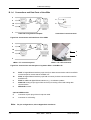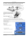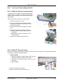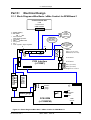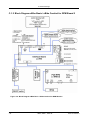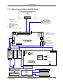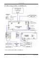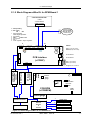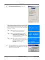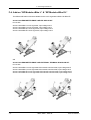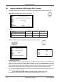
1
eBike / eBike L / eBike EL Service Manual 2018112-003 2018112-003 Rev I Revision I eBike, eBike L, eBike EL -I- Manual Information Caution: During repairs/service interventions, observe the protective measures against damage due to ESD. • • • • GE Medical Systems Information Technologies GmbH considers itself responsible for the effects on safety, reliability, and performance of the equipment, only if: assembly operations, extensions, readjustments, modifications, or repairs are carried out by GE Medical Systems Information Technologies GmbH or by persons authorized by GE Medical Systems Information Technologies, the electrical installation of the relevant room complies with the applicable national and local requirements, and the instrument is used in accordance with the instructions for use. This manual contains service information; operating instructions are provided in the operator’s manual of the instrument. This manual is in conformity with the instrument at printing date. All rights are reserved for instruments, circuits, techniques, and names appearing in the manual. The Service Manual eBike is valid for the following devices: 2017911-001 ERGOMETER EBIKE BASIC PC-CTRL 2017911-002 ERGOMETER EBIKE BASIC PCPLUS-CTRL 2017911-003 ERGOMETER EBIKE BASIC PC-CTRL & BP 2017911-004 ERGOMETER EBIKE BASIC PCPLUS-CTRL & BP 2017911-005 ERGOMETER EBIKE COMFORT PC-CTRL 2017911-006 ERGOMETER EBIKE COMFORT PCPLUS-CTRL 2017911-007 ERGOMETER EBIKE COMFORT PC-CTRL & BP 2017911-008 ERGOMETER EIBKE COMFORT PCPLUS-CTRL&BP 2017911-020 ERGOMETER EBIKE L 240V 2017911-021 ERGOMETER EBIKE L & BP 240V 2017911-022 ERGOMETER EBIKE L EXT TRMNL 240V 2017911-023 ERGOMETER EBIKE L & BP EXT TRMNL 240V 2017911-024 ERGOMETER EBIKE L 120V 2017911-025 ERGOMETER EBIKE L & BP 120V 2017911-026 ERGOMETER EBIKE L EXT TRMNL 120V 2017911-027 ERGOMETER EBIKE L & BP EXT TRMNL 120V 2017911-028 ERGOMETER EBIKE EL 240V 2017911-029 ERGOMETER EBIKE EL & BP 240V 2017911-030 ERGOMETER EBIKE EL EXT TRMNL 240V 2017911-031 ERGOMETER EBIKE EL & BP EXT TRMNL 240V 2017911-032 ERGOMETER EBIKE EL 120V 2017911-033 ERGOMETER EBIKE EL & BP 120V 2017911-034 ERGOMETER EBIKE EL EXT TRMNL 120V 2017911-035 ERGOMETER EBIKE EL & BP EXT TRMNL 120V optional with Module "N I B P" and all Supply and Service Items and Software Version FW 1.8 Manufacturer: ergoline GmbH Lindenstraße 5 D-72475 Bitz Tel.: +49 (0) 7431 98 94 - 0 Fax: +49 (0) 7431 98 94 - 127 e-mail: [email protected] internet: http://www.ergoline.com Distributor: GE Medical Systems Information Technologies, Inc. 8200 West Tower Avenue Milwaukee, WI 53223 USA Tel. +1.414.355.5000 888.558.5120 (USA only) Fax +1.414.355.3790 ©Copyright 2003, 2008. General Electric Company. All rights reserved. - II - eBike, eBike L, ebike EL 2018112-003 Rev I Revision History Revision History This manual is subject to the GE Medical Systems Information Technologies change order service. The revision code, a letter that follows the document part number, changes with every update of the manual. The initial version of the manual has the letter A. Part No. 2018112-003 2018112-003 2018112-003 2018112-003 2018112-003 2018112-003 2018112-003 2018112-003 Revision Code Rev A Rev B Rev C Rev D Rev E Rev F Rev G Rev H Date 2003-11 2004-04 2004-08 2005-01 2005-03 2005-09 2006-12 2007-10 2018112-003 Rev I 2008-03 2018112-003 Rev I eBike, eBike L, eBike EL Comment Initial Release 076092 077414 079503: eBike L&EL added 079947: V1.4 PC/PCplus 081381 ECO 085810: V1.6 ECO 089049: V1.6 replaced by V1.7 Revised pages: II, 3, 4, 5, 55, 56, 57, 60, 68 V1.7 replaced by V1.8 Revised pages: II, III, 3-6, 17, 25, 26, 32, 33, 47, 57-59, 85, 86, 93, 94 - III - Contents CONTENTS A-1 Safety Information .................................................................................................. 1 Inspection according to German Medical Device Operator Ordinance............................. 2 A-2 Final Checkout Procedure / Functional Test ........................................................ 3 A-2.1.Final Checkout Procedure and Functional Test of eBike Basic, eBike Comfort ...... 3 A-2.2. Final Checkout Procedure and Functional Test of eBike L ..................................... 4 A-2.3. Final Checkout Procedure and Functional Test of eBike EL .................................. 5 Part B. Mechanical Design ............................................................................................ 9 B.1 Operating Controls and Connections of eBike ............................................................ 9 B.1.a Operating Controls .................................................................................................. 9 B.1.b Operating Controls and Connections of eBike L .................................................... 10 B.1.c Operating Controls and Connections of eBike EL .................................................. 11 B.1.d Connections and Data Ports of the eBike .............................................................. 12 B.2 Overview: Mechanical Design eBike ........................................................................ 13 B-2.1 Overview: Disassembling the eBike basic/comfort ............................................... 14 B-3. Overview: Mechanical Design eBike L ................................................................... 21 B-3.1 Overview: Disassembling eBike L ........................................................................ 22 B-3.1.1 eBike L: Remove Connection Box ................................................................................................ B-3.1.2 eBike L: Remove Casing .............................................................................................................. B-3.1.3 eBike L: Replace Saddle Motor .................................................................................................... B-3.1.4 eBike L: Install Power Supply Module for eBike L (P/N 2018111-142) ............................................ B-3.1.5 eBike L: Replace Lift Motor for Couch Adjustment ........................................................................ B-3.1.6 eBike L: Replace Motor Control Unit ............................................................................................. B-3.1.7 eBike L Basic: Replace Control Panel .......................................................................................... B-3.1.8 eBike L External: Replace External Speed Indicator ...................................................................... 22 22 24 25 26 27 27 27 B-4.Overview: Mechanical Design eBike EL .................................................................. 28 B-4.1 Overview: Disassembling eBike EL ...................................................................... 29 B-4.1.1 eBike EL: Remove Connection Box .............................................................................................. B-4.1.2 eBike EL: Remove Casing ............................................................................................................ B-4.1.3 eBike EL: Replace Saddle Motor .................................................................................................. B-4.1.4 eBike EL: Install Power Supply Module for eBike EL (P/N 2018111-142) ....................................... B-4.1.5 eBike EL: Replace Lift Motors for Couch Adjustment .................................................................... B-4.1.6 eBike EL: Replace Motor Control Unit ........................................................................................... B-4.1.7 eBike EL Basic: Replace Control Panel ........................................................................................ B-4.1.8 eBike EL External: Replace External Speed Indicator ................................................................... 29 29 31 32 33 34 35 35 Part C. Electrical Design ............................................................................................. 37 C-1.1 Block Diagram eBike Basic / eBike Comfort for RPM Board 1 ............................. 37 C-1.2 Block Diagram eBike Basic / eBike Comfort for RPM Board 2 ............................. 38 C-1.3 Block Diagram eBike L for RPM Board 1 ............................................................. 39 C-1.4 Block Diagram eBike L for RPM Board 2 ............................................................. 40 C-1.5 Block Diagram eBike EL for RPM Board 1 ........................................................... 41 C-1.6 Block Diagram eBike EL for RPM Board 2 ........................................................... 42 C-2.1 Wiring Diagram eBike Basic / eBike Comfort ....................................................... 43 C-2.2 Wiring Diagram eBike L ....................................................................................... 44 - IV - eBike, eBike L, ebike EL 2018112-003 Rev I Contents C-2.3 Wiring Diagram eBike EL .................................................................................... 45 C-3 Overview: PCBs eBike ............................................................................................ 46 C-4 Overview: DIP Switch and Jumper Settings ............................................................. 48 Part D: Service Menu for eBike Basic / Comfort / L / EL ........................................... 49 Part E: Drive Unit ......................................................................................................... 65 E-1. Drive Unit - Mechanical Design ............................................................................... 65 E-2. Troubleshooting and Repairs .................................................................................. 67 E-2.1 Replace Strain Gauge........................................................................................... 67 E-2.2 Replace PCB RPM ............................................................................................... 67 E-2.3 RPM Board : Replacement and Adjustment Procedure ......................................... 68 Part F: Servicing Instructions .................................................................................... 71 F-1. Spare Parts for Repair of eBike .............................................................................. 71 F-2. Spare Parts for Repair of eBike L / eBike EL .......................................................... 72 F-3. Add-on “BP Module eBike“ ..................................................................................... 73 F-4. Add-on “BP Module eBike L“ & “BP Module eBike EL“ ........................................... 74 Appendix A: Interfaces ................................................................................................ 75 A.1 Digital Interfaces PORT 1 and PORT 3 .................................................................... 75 A.1 a Setup for: Digital ECG Unit ................................................................................... 76 A.2 Digital Interface PORT 2: For SERVICE PURPOSES only ....................................... 77 A.3 Analog Interfaces With Digital Data Transfer............................................................. 78 Appendix B: Spare Parts / Service Kits for eBike ..................................................... 79 Appendix B.2: Spare Parts / Service Kits for eBike L / eBike EL ............................. 90 Appendix C.1: Technical Specifications eBike Basic / eBike Comfort .................. 103 Appendix C.2: Technical Specifications eBike L .................................................... 105 Appendix C.3: Technical Specifications eBike EL .................................................. 106 2018112-003 Rev I eBike, eBike L, eBike EL -V- For your notes - VI - eBike, eBike L, ebike EL 2018112-003 Rev I A: Safety Information A-1. Safety Information Electrical Safety During Service Interventions (IEC 60601-1) IEC 60601-1 requirements must be satisfied during repair, modifications and inspections of medical electrical equipment. Under the regulations of the product liability act, equipment manufacturers must ensure that their product does not present any hazard to the user in normal use. The potential hazards must be considered in particular when handling mains operated devices. To ensure that equipment functions faultlessly and without presenting any hazard after service interventions, it must be subjected to the test procedures stipulated for the different device categories. Requirements for Persons stipulated in the German Medical Device Operators Ordinance: The requirements of §11 section 6, §11 section 5 sentence 1 and §6 section 4 of the MPBetreibV (German Medical Device Operator Ordinance) must be satisfied. The regulations about handling ESD sensitive components must be observed. 1. Protection class I equipment (connected to protective earth conductor) max. resistance of the protective earth conductor R protective earth conductor (with connection cable with max. length of 5 m) max. equivalent enclosure leakage current for portable equipment. max. equivalent enclosure leakage current 0.100 Ohm 0.500 mA The measuring equipment used for the tests must be inspected and calibrated at regular intervals. As per the German Medical Device Operator Ordinance, the measurement results must be documented in the medical device book. Note Suitable common ground terminal: - Bicycle ergometer eBike Basic / Comfort: screw of the levelling device - Ergometer eBike L/EL: screw head of the protective earth connection between swivelling section and ergometer base A device is considered to be unsafe, when - it cannot be repaired - the user does not wish to have the device repaired. In this case, the operator must be informed in writing of the hazard presented by the device. The same remark must be annotated on the service report and on the service invoice. Important information for service interventions: - Use original spare parts only. - For information about product changes, refer to the manufacturer’s original documentation only. - Observe the fuses’ original ratings, characteristics and Ampere interrupting capacity. - Parts of the device that ensure its safe operation must be neither damaged nor obviously unsuitable. This applies to insulation and insulating components in particular. - Power cords must be visually inspected for signs of damage before connecting them to the power line. 2018112-003 Rev I eBike, eBike L, eBike EL -1- A: Safety Information Inspection according to German Medical Device Operator Ordinance: • Technical Safety Inspections and Inspections of the Measuring Systems: According to §6 and §11 of the German Medical Device Operator Ordinance, the load unit must be inspected to the approved rules of the art at intervals of 2 years by a GE Medical Systems Information Technologies authorized Service technician, and repaired if necessary. The measurement results must be documented in the medical device book. According to the German Medical Device Operator Ordinance, the next due inspection is indicated on the Test Sticker next to the ergometer’s nameplate. If unauthorized personnel opens the control terminal, destroying the calibration sticker (production date), any warranty claim shall become void. • Maintenance: Depending on the application purpose, all clamping levers of the device must be inspected at intervals of 6 months to check that the thread and tip of the clamping lever are adequately greased. If necessary, the clamping levers must be greased. We recommend using a universal high-performance lubricant such as OKS 470. Note §11 of the German Medical Device Operator Ordinance demands that ergometers used in medicine, i.e., ergometers for exercising patients with a defined and reproducible physical load, be calibrated with a dynamic load. The technical inspection of the measuring system is not required for ergometers used for training purposes only and where the tests are not documented. The restricted applicability must be identified by a suitable marker on the ergometer and it must be documented in the medical device book. Automatic Sphygmomanometer Calibration instructions for the NIBP module can be found in the Servicing Instructions. Follow these instructions to display the BP values with the test setup according to DIN EN 1060-1 and DIN EN 1060-3. Ergometer Static and dynamic inspections of the ergometer must be performed according to DIN VDE 0750238. -2- eBike, eBike L, eBike EL 2018112-003 Rev I A: Final Checkout Procedure / Functional Test A-2. Final Checkout Procedure / Functional Test These tests must be performed as the final checkout and test procedure after every safety inspection, maintenance and repair of the product. A-2.1. Final Checkout Procedure and Functional Test of eBike Basic, eBike Comfort 1. Visually inspect the device - Inspect coat of lacquer, cables/power cord, bellows on steering column and saddle. - Inspect cuff, tubing and tubing connection. - Check the setup for stability, adjust with levelling device if required. Expected result: No damage, instability or wear detected Pass/Fail 2. Check cranks, pedals and Velcro strips - Cranks, pedals and Velcro strips properly fixed. - Grease the threads of the clamping levers (every 6 months, depending on application purpose). Expected result: All threads properly greased, cranks and pedals OK Pass/Fail 3. Power on - Using the power cord, connect the device to the power line and turn it on with the power switch. - Wait for self-test to end: Check LCD, e.g. for error messages. - Check in the software if the firmware version is OK. Expected result: Device powers on without errors and FW is OK Pass/Fail 4. Adjustments eBike Basic: - Check saddle (height) and handlebar (angle) adjustment. - Check that the clamping levers (saddle (height) and handlebar (angle) adjustment) are tight. eBike Comfort: - Check electrical saddle adjustment: adjust minimum and maximum saddle height; then return saddle to mid-level. - Check handlebar adjustment (height and angle). - Check that the clamping levers (handlebar height and angle) are tight. Expected result: Adjustments work and levers are tight Pass/Fail 5. Speed and Noise - Check speed indication on LCD and additional speed indication for test subject. - Check noise level of idling drive unit (e.g., for grinding noises or noise from the bearing). Expected result: Speed displayed on both displays and no noticeable noise Pass/Fail 6. NIBP module (if applicable) - Check blood pressure measurement on test subject at rest. - Check blood pressure readings on LCD. Expected result: BP values are displayed and in proper range 2018112-003 Rev I eBike, eBike L, eBike EL Pass/Fail -3- A: Final Checkout Procedure / Functional Test 7. Exercise test - Start manual exercise test, e.g. initial load of 50 Watts / load change of 25 Watts. - Check load level and load indication. Expected result: Load changes as expected Pass/Fail 8. Communication (if applicable) - If ergometer is remote-controlled from EKG unit or PC-ECG system, check connection cable. - Check load control vial EKG unit or PC ECG system. - Check remote start if applicable. Expected result: Ergometer can be controlled by external unit Pass/Fail A-2.2 Final Checkout Procedure and Functional Test of eBike L 1. Visually inspect the device - Inspect coat of lacquer, cables/power cord, bellows on steering column and saddle. - Inspect footboard for stability. - Inspect cuff, tubing and tubing connection. - Inspect couch adjustment motor for damage. - Check the setup for stability, lock castor brakes, if required. Expected result: No damage, instability or wear detected Pass/Fail 2. Check rests, cranks, pedals and Velcro strips - Check that all clamping levers and star grips are firmly seated. - Check that cranks, pedals, Velcro strips and pedal shoes are properly fixed. - Inspect leg rests and their attachment, if leg rests are installed. - Inspect head and arm rests as well as handgrips. - Grease the threads of the clamping levers (every 6 months, depending on application purpose). Expected result: All threads properly greased, cranks, rests and pedals OK Pass/Fail 3. Power on - Using the power cord, connect the device to the power line and turn it on with the power switch. - Wait for self-test to end: Check LCD, e.g. for error messages. - Check in the software if the firmware version is OK. Expected result: Device powers on without errors and FW is OK Pass/Fail 4. Couch adjustment motor - Set motor to both stop positions. - Change couch position from horizontal (0°) to semi-recumbent (45°) and then back to the horizontal position (0°). Expected result: Couch position changes to the expected positions Pass/Fail 5. Saddle adjustment motor - Check all possible positions by moving the saddle to the top and to the bottom position. - Return saddle to the middle position. Expected result: Saddle position changes to the expected positions Pass/Fail -4- eBike, eBike L, eBike EL 2018112-003 Rev I A: Final Checkout Procedure / Functional Test 6. Speed and Noise - Check speed indication on LCD and additional speed indication for test subject. - Check noise level of idling drive unit (e.g., for grinding noises or noise from the bearing). Expected result: Speed displayed on both displays and no noticeable noise Pass/Fail 7. NIBP module (if applicable) - Check blood pressure measurement on test subject at rest. - Check blood pressure readings on LCD. Expected result: BP values are displayed and in proper range Pass/Fail 8. Exercise test - Start manual exercise test, e.g. initial load of 50 Watts / load change of 25 Watts. - Check load level and load indication. Expected result: Load changes as expected Pass/Fail 9. Communication (if applicable) - If ergometer is remote-controlled from EKG unit or PC-ECG system, check connection cable. - Check load control vial EKG unit or PC ECG system. - Check remote start if applicable. Expected result: Ergometer can be controlled by external unit Pass/Fail A-2.3 Final Checkout Procedure and Functional Test of eBike EL 1. Visually inspect the device - Inspect coat of lacquer, cables/power cord, bellows on steering column and saddle. - Inspect footboard for stability. - Inspect cuff, tubing and tubing connection. - Inspect couch adjustment motor for damage. - Check the setup for stability, lock castor brakes, if required. - Inspect outrigger. Expected result: No damage, instability or wear detected Pass/Fail 2. Check rests, cranks, pedals and Velcro strips - Check that all clamping levers and star grips are firmly seated. - Check that cranks, pedals, Velcro strips and pedal shoes are properly fixed. - Fold down drop section. - Inspect leg rests and their attachment, if leg rests are installed. - Adjust and inspect hip support. - Inspect head and arm rests as well as handgrips. - Grease the threads of the clamping levers (every 6 months, depending on application purpose). Expected result: All threads properly greased, cranks, rests and pedals OK Pass/Fail 3. Power on - Using the power cord, connect the device to the power line and turn it on with the power switch. - Wait for self-test to end: Check LCD, e.g. for error messages. - Check in the software if the firmware version is OK. Expected result: Device powers on without errors and FW is OK Pass/Fail 2018112-003 Rev I eBike, eBike L, eBike EL -5- A: Final Checkout Procedure / Functional Test 4. Both couch adjustment motors - Set both motors to both stop positions. - Change couch position from horizontal (0°) to semi-recumbent (45°) and then back to the horizontal position (0°). - Check adjustment range for lateral tilt from the horizontal position (0°). Expected result: Couch position changes to the expected positions Pass/Fail 5. Saddle adjustment motor - Check all possible positions by moving the saddle to the top and to the bottom position. - Return saddle to the middle position. Expected result: Saddle position changes to the expected positions Pass/Fail 6. Speed and Noise - Check speed indication on LCD and additional speed indication for test subject. - Check noise level of idling drive unit (e.g., for grinding noises or noise from the bearing). Expected result: Speed displayed on both displays and no noticeable noise Pass/Fail 7. NIBP module (if applicable) - Check blood pressure measurement on test subject at rest. - Check blood pressure readings on LCD. Expected result: BP values are displayed and in proper range Pass/Fail 8. Exercise test - Start manual exercise test, e.g. initial load of 50 Watts / load change of 25 Watts. - Check load level and load indication. Expected result: Load changes as expected Pass/Fail 9. Communication (if applicable) - If ergometer is remote-controlled from EKG unit or PC-ECG system, check connection cable. - Check load control vial EKG unit or PC ECG system. - Check remote start if applicable. Expected result: Ergometer can be controlled by external unit Pass/Fail -6- eBike, eBike L, eBike EL 2018112-003 Rev I Only valid for Germany! Blatt 1 von 1 Prüfprotokoll gemäß MPBetreibV §6 Sicherheitstechnische Kontrolle §11 Messtechnischen Kontrolle Prüfprotokollnr.: Ergometer eBike, eBike L, eBike EL _______________ Die durchgeführten und nachfolgend dokumentierten Prüfungen sind das Ergebnis einer messtechnischen Kontrolle gemäß MPBetreibV ergänzt durch gerätespezifische Zusatzanforderungen von GEMS IT. Geprüftes Ergometer: Type: ________________ Serien Nr.: _________________ Letzte Überprüfung: Datum: ________________ Software: _________________ SEV: (VDE0751) Drehzahl [min-1] SL-Widerstand <0,3 Ohm Soll 30 40 50 100 120 gemessen: ________ Ohm Ersatzgeräteableitstrom <0,75mA gemessen: _________ mA Ist [±1] Leistung [W] Soll max. Abw. Befund Ist Regelverhalten < 3 Watt oder ± 5% 40 40 40 70 90 100 Messgerät Type: ________ Serien Nr.: _____________ Messgerät Type: ________ Serien Nr.: _____________ Messgerät Type: ________ Serien Nr.: _____________ Messgerät Type: ________ Serien Nr.: _____________ 25 50 100 200 500 600 Prüfstand Type: ± 3 Watt ±3 Watt ±5Watt ±10 Watt ±25 Watt ±30 Watt SN: geprüft bis: Prüf ID.Nr.: Separates Protokoll 7-Segment-Anzeige vollständig? Ergometergehäuse unbeschädigt? LCD-Kontrast in Ordnung? Spannungsführende Teile nicht berührbar? Lenkerstange Befestigung/unbeschädigt? Messkopf unbeschädigt? Sattelstange Befestigung/unbeschädigt? Tastatur unbeschädigt/Funktion ok? Mechanische Sattelverstellung ok? Sattel- und Lenkerklemmung gefettet? Elektrische Sattelverstellung ok? (nur Comfort/L/EL) Elektrische Liegenverstellung ok (nur L/EL)? Mechanische Gerätestütze ok (nur EL)? Elektrische Seitenverstellung ok (nur EL)? Bedienungsanleitung vorhanden? Medizinproduktebuch vorhanden? bestanden nicht bestanden Bemerkungen: Jahr der nächsten notwendigen messtechnischen Kontrolle: Datum: ______________________ Unterschrift 20_ _ : __________________________ GE Medical Systems Information Technologies GmbH, Munzinger Str. 3, D-79111 Freiburg, Germany 2018112-003 Rev I eBike, eBike L, eBike EL -7- Only valid for Germany! Blatt 1 von 1 Prüfprotokoll über die Ergebnisse der messtechnischen Kontrolle gemäß §11, MPBetreibV Prüfprotokollnr.: Blutdruckmessgerät im Ergometer _______________ Die durchgeführten und nachfolgend dokumentierten Prüfungen sind das Ergebnis einer messtechnischen Kontrolle gemäß DIN EN 1060-1 und DIN EN 1060-3, ergänzt durch gerätespezifische Zusatzanforderungen von GEMS IT. Geprüftes Ergometer: Typ: ___________ Letzte Kalibrierung: Datum: ___________ Serien Nr.: ___________ Da bei der messtechnischen Kontrolle Ihres Medizinproduktes das Medizinproduktebuch nicht vorlag, werden Sie gebeten, die nachstehenden Angaben für Ihre Dokumentation zu verwenden. Durchgeführte Prüfung Prüfergebnis/ermittelte Werte i.O. 1. Sichtprüfung: 2. Funktionsprüfung: 3. Luftundichtheitsprüfung [< 6 mmHg/min.] Bemerkungen n.i.O. BDM-Werte: systolisch: _________ mmHg diastolisch: _________ mmHg Pulsrate: _________ min-1 Proband Patientensimulator Druckabfall (50 mmHg): _______ mmHg/min. Druckabfall (300 mmHg): _______ mmHg/min. 4. Anzeigefehler des Manschettendrucks (nach Aufpumpen ca. 3 Sek. abwarten) mmHg eingesetzte Prüf-/Messmittel [ ± 3 mmHg] 0 50 100 150 200 250 300 Bezeichnung, Typ Seriennummer - Kalibriertes Druckmessgerät - Patientensimulator für Blutdruck - Sonstige - Sonstige - Sonstige bestanden nicht bestanden Bemerkungen: Jahr der nächsten turnusmäßigen messtechnischen Kontrolle: Datum: ______________________ Unterschrift 20_ _ : __________________________ GE Medical Systems Information Technologies GmbH, Munzinger Str. 3, D-79111 Freiburg, Germany -8- eBike, eBike L, eBike EL 2018112-003 Rev I B: Mechanical Design Part B. Mechanical Design B.1 Operating Controls and Connections of eBike B.1.a Operating Controls eBike basic with control terminal PC eBike comfort with control terminal PCplus 6 5 7 5 13 11 11 14 8 8 16b 16a 9a 9b 15 10 3 4 17 18 1, 2 12 3 12 Figure B-1: Operating controls of bicycle ergometers eBike basic / comfort 1 2 3 4 5 6 7 8 9a 9b 10 Power input with mains fuse (section 2.3.1) Interfaces (on bottom of ergometer) Power switch Nameplate with serial number Control terminal with LCD and operating controls Speed indication for patient Handlebar Bellows on steering column eBike basic: Steering column (fixed height) eBike comfort: Steering column, height adjustable eBike comfort: Clamping lever for height adjustment of the handlebar 2018112-003 Rev I 11 12 13 14 15 16a 16b 17 18 Clamping lever for angle adjustment of the handlebar Castors Saddle Steering tube with bellows for saddle LED indicating saddle height eBike basic: Clamping lever for saddle adjustment eBike comfort: Motor-driven saddle adjustment Pedal Levelling device for optimum stability eBike, eBike L, eBike EL -9- B: Mechanical Design B.1.b Operating Controls and Connections of eBike L 10 1 11 2 3 4 11 NIBP 5 eBike 12 6 13 7 14 8 9 Figure B-2: Operating controls of bicycle ergometers eBike L 1 2 3 4 5 6 7 - 10 - Clamping lever for adjustment of the head support Arm rest for blood pressure measurements (right or left, on systems with blood pressure module only) Handgrip (prop for mounting the bed and dismounting) Speed readout for patient Control terminal Power switch Connector panel (power input, fuses, etc.) 8 9 10 11 12 Leg rest (option) Castors, locking Paper roll Remote control for adjustment of bed surface and saddle Connector for blood pressure cuff, on both 13 14 sides of the bed, type B applied part ( ) (on systems with blood pressure module only) Nameplate Footboard eBike, eBike L, eBike EL 2018112-003 Rev I B: Mechanical Design B.1.c Operating Controls and Connections of eBike EL 10 1 11 2 3 12 4 NIBP 5 13 eBike 14 15 16 6 17 18 7 19 8 9 Figure B-3: Operating controls of bicycle ergometers eBike EL 1 2 3 4 5 6 7 8 9 10 Clamping lever for adjustment of the head support, release button for drop section 14 Arm rest for blood pressure measurements (on stress-echo beds with blood pressure module only) Handgrip (prop for mounting the bed and dismounting) Speed readout for patient Control terminal Power switch Connector panel (power input, fuses, etc.) Leg rest (option) Castors, locking Paper roll 2018112-003 Rev I 11 12 13 14 15 Upper handgrip, adjustable Remote control for adjustment of bed surface and saddle Armpit support, adjustable Drop section Connector for blood pressure cuff, on both 16 17 18 19 sides of the bed, type B applied part ( ) (on stress-echo beds with blood pressure module only) Hip support, adjustable Nameplate Outrigger Footboard eBike, eBike L, eBike EL - 11 - B: Mechanical Design B.1.d Connections and Data Ports of the eBike 3 2 5 1b 6 1a 4 Underside of ergometer baseplate Underside of control terminal Figure B-2: Connections and Data Ports of the eBike 3 2 1b 6 1a 5 4 eBike L / EL connection panel eBike L / EL cuff connection Figure B-3: Connections and data ports of systems eBike L and eBike EL 1a 1b 2 3 4 PORT 1: Digital RS232 interface (9-pin Sub-D) for data communication with PC and EKG unit and output for remote start of the EKG unit. PORT 3: Digital RS232 interface (5-pin DIN connector) for data communication with PC and EKG unit. PORT 2: Additional digital RS232 interface, e.g., for software updates ANALOG: Analog I/O port (8-pin DIN connector) for analog control and analog data communication. SERVICE not used. optional: NIBP module 5 Connector for jack plug of the microphone cable. 6 Connector for cuff tubing. Note: For pin configurations, refer to Appendix A: Interfaces. - 12 - eBike, eBike L, eBike EL 2018112-003 Rev I B: Mechanical Design B.2 Overview: Mechanical Design eBike B4 -4 B4-9 B4-3 B4-4a B4-4b B4-2 B4-1 B4-6a B4-5a B4-6b B4-5b B4-7 B4-8 Figure B-4: Mechanical design of bicycle ergometers eBike basic Item No. Part No. Description B4-1 B4-2 B4-3 B4-4 Ergometer base Load unit, fully assembled for eBike Power supply with power switch Control terminal PC (B2-4a) and control terminal PCplus (B2-4b) B4-5 B4-6 B4-7 B4-8 B4-9 Casing eBike basic (B2-5a) and casing eBike comfort (B2-5b) Cover, grey (B2-6a) and cover, blue (B2-6b) PCB Interface in base assembly Pump unit for BP module in base assembly (optional) Saddle motor (eBike comfort only) 2018112-003 Rev I eBike, eBike L, eBike EL - 13 - B: Mechanical Design B-2.1 Overview: Disassembling the eBike basic/comfort We recommend using the following tools to disassemble the device: Flat bladed screwdrivers: 1 pc. 1.0 x 0.18 1 pc. 1 pc. 4.0 x 0.8 1 pc. 6.0 x 1.2 Philips screwdrivers: PH 1 1 pc. PH 2 1 pc. PH 3 Fork wrenches: 1 pc. 5.5 mm 2 pc. 7 mm 1 pc. 13 mm 1 pc. 17 mm 1 pc. 19 mm Allan keys: 1 pc. 1 pc. 1 pc. 1 pc. 1 pc. 2.5 mm 3 mm 4 mm 5 mm 6 mm Socket wrenches : 1 pc. 5.5 mm 1 pc. 13 mm Pliers 1 pc. 1 pc. 1 pc. side cutter flat nose pliers multigrip pliers straight straight and elbow straight and elbow straight straight and elbow Special tools 1 pc. crank extractor 2 pc. round pin, max. 3 mm, minimum length 15 mm NOTE: Use the same tools to disassemble eBike L and eBike EL. Two wide metal angles may be required to remove the ergometer casing (side length approx. 1.5 cm x 15 cm). - 14 - eBike, eBike L, eBike EL 2018112-003 Rev I B: Mechanical Design PCB Interface (item a.) and the pneumatic unit of the BP module (item b.) can be removed without disassembling the device. a. Remove PCB Interface 1. Disconnect device from mains! 2. Swivel handlebar to the front and tilt the ergometer 90°. The ergometer rests on the handlebar and the base assembly is accessible. 3. Disconnect all cables from PCB Interface (power cord and data cables). 4 Unscrew the 4 Philips screws and pull out PCB Interface. 5. If necessary, disconnect the cables from PCB Interface. On the PCB you will find designations for the different connectors, e.g. Messkopf X150. b. Remove Pneumatic Unit of the Blood Pressure Module 1. Disconnect device from mains! 2. Remove PCB Interface, see item a. 3. Disconnect NIBP X201 cable from PCB Interface. 4. Unscrew the 4 Philips screws and remove the pneumatic unit. 5. Disconnect NIBP tubing. c. Remove Top Cover Two plastic tabs hold the top cover in place in the housing. By inserting a tool such as a round pin with a max. diameter of 3 mm in a hole on the left and on the right you can press these tabs towards the inside. - Using the round pins (max. diameter of 3 mm), simultaneously press in the the plastic tabs on the left and right and lift off the cover 2018112-003 Rev I eBike, eBike L, eBike EL - 15 - B: Mechanical Design d. Remove Casing The shells of the casing must only be removed for repairs on the drive unit and on the power supply. 1. Disconnect device from mains! 2. Remove top cover (see item c.) 3. Take off right and left pedals. • Remove protective cover from pedals. • Using the extractor (P/N 2005737-001), unscrew the screw in the axle and remove (17-mm fork wrench required) • Screw the extractor at least half way into the pedal axle (see Figure) Turn the half of the extractor that points away from the axle to the right until the pedal can be removed. 4. Take off front wheels • Using a thin screwdriver, carefully unseat the caps covering the wheels. • Remove snap ring from wheel retention. • Take off both wheels. • Unscrew screw of the threaded bolt on one side at the front and remove threaded bolt. 5. Pull bellows for steering column and saddle over retaining groove. • Using an Allan key, remove threaded screw of the steering column and saddle housing (3-mm Allan key required). 6. Using a long 3-mm Allan key, remove both screws on the right and left of the drive unit casing. 7. Remove front and rear connection piece. • Loosen each hexagon socket screw on one side. • Remove front and rear connection piece. - 16 - eBike, eBike L, eBike EL 2018112-003 Rev I B: Mechanical Design 8. Remove casing. • Using a screwdriver with a wide blade, carefully spread he casing at the front, then at the rear. • Carefully separate the two shells. 9. Reverse the above steps to reassemble. e. Install Power Supply Module for eBike basic & comfort (P/N 2018111-141) Replacement of large power supply ERS80US24M or small power supply EMC60US24. • Install the ground wire of the power supply to the base frame as shown in the illustration. PE Nut M3 Washer 3,2 Power supply board Lock washer 3,2 Standoff M3 12mm Holding plate power supply Lock washer 3,2 Fillister head screw M3x8 PE 2018112-003 Rev I eBike, eBike L, eBike EL - 17 - B: Mechanical Design f. Remove Saddle Motor (eBike comfort only) Note: Position the saddle at mid-level before removing the saddle motor. Once the power supply has been removed, you can proceed to removing the saddle motor. • • • • • • • • Disconnect connection cable of the saddle motor from PCB Interface Sitz-Motor X152 and the connection cable of the saddle height sensor Sitz-Sens X155. Remove the saddle and pull off the bellows. Remove saddle host - to do so, unscrew both screws at the top, push down the saddle tube to allow the cylindrical pin to be removed from the saddle shaft. Remove clamping plate from saddle tube. Pull saddle tube off the saddle motor. Unscrew the 4 screws of the saddle guide tube and remove the tube. Loosen bottom fixation of the saddle motor (screw and nut are accessible via a hole at the bottom). Remove the saddle motor. g. Remove Saddle Tube (eBike basic) Once the power supply has been removed, you can proceed to removing the saddle tube. • Disconnect connection cable of the seat height sensor Sitz-Sens X155. • Remove the saddle and pull off the bellows. • Disconnect saddle height sensor from saddle tube. • Loosen clamping lever of the saddle tube and pull out the saddle tube. When loosening the clamping lever, take care not to drop the clamping plate. • Unscrew the 4 screws of the saddle guide tube and remove the tube. h. Remove/Install Saddle Height Sensor (eBike basic) Once the power supply has been removed, you can proceed to removing the saddle saddle height sensor. • Disconnect connection cable of the saddle height sensor from PCB Interface Sitz-Sens X155. • Disconnect saddle height sensor from saddle tube. • Unscrew the 2 screws securing the saddle height sensor and remove the sensor. - 18 - eBike, eBike L, eBike EL 2018112-003 Rev I B: Mechanical Design i. Remove Steering Column (incl. laying cables) Before the steering column and the cables (spiral hose + cable connecting control terminal to PCB Interface) can be removed, PCB Interface, the pneumatic system of the BP module and the power supply must be removed. • Remove the control terminal. • Disconnect the cable connecting the control terminal to PCB Interface Messkopf X150. • Disconnect NIBP tubing. • • • • Open cable ties of connection cable and spiral hose (see illustrations). Pull connection cable and spiral hose towards the steering column. Loosen clamping lever (eBike comfort) securing the handlebar or loosen fixation of the steering column (eBike basic). Caution: ultra-tight screw lock. In each case take care not to drop the clamping plate. Lift off the steering column. Note: When installing the steering column with the spiral hose and connection cable, cable and hose must be slack and secured with cable ties (see illustrations). j. Remove Drive Unit • Disconnect connection cable of PCB RPM X200 from PCB Interface. • Unscrew the 6 screws (M8x20) of the drive unit and lower the drive unit. k. Remove PCB RPM • Disconnect the PCB RPM cable J3. • Remove connection J5 to strain gauge. • Unscrew the two screws of PCB RPM. • Disconnect the two cables (red + blue) to the eddy-current brake. 2018112-003 Rev I eBike, eBike L, eBike EL - 19 - B: Mechanical Design l. Remove Strain Gauge and Prestress Spring Refer to section E-3.2.1 for removal of the strain gauge. • Carefully loosen the strain gauge. The retaining ball of the micro rope must not touch the rubber layer of the strain gauge (risk of destruction). • Disconnect cable from J5 on PCB RPM. • Remove both hexagon socket screws of the strain gauge. • Loosen both hexagon socket screws of the prestress spring and remove spring. • Remove sealing varnish and take off both micro ropes. m. Disassemble Control Terminal Caution: Opening the control terminal will destroy the safety seal. Therefore, the inspection of the BP measuring system may have to be repeated once the control terminal has been opened. • Remove the control terminal from the ergometer. • Open control terminal (remove safety seal and loosen the 4 screws). • Take off bottom shell of the control terminal, then remove the electronic part that is secured with 4 screws. • Pull out the control terminal panel. Device with BP Functionality: • • • • Lift off PCB BP by squeezing the plastic locking pins. Remove cable ties. Remove cable connecting PCB BP to PDB Display. Disconnect air tubing. When reassembling the control terminal, ensure proper positioning of cables and tubing. - 20 - eBike, eBike L, eBike EL 2018112-003 Rev I B: Mechanical Design B-3. Overview: Mechanical Design eBike L B5-9 B5-9 B5-11 B5-10 B5-8 B5-3 B5-1 B5-2 B5-7 B5-4 B5-5 B5-6 Figure B5: Mechanical Design Couch Ergometer eBike L Item No. Description B5-1 B5-2 B5-3 B5-4 B5-5 B5-6 B5-7 B5-8 B5-9 Base of couch ergometer eBike L Load unit, installed Connection box with interface board and ON/OFF switch Power supply, installed for eBike L Modular cable connection Blood pressure pump module for eBike L (optional), mounted Lift motor for couch adjustment for eBike L Saddle motor for eBike L Motor control with hand switch, 2 channels for eBike L (1 - lift motor, 2 - saddle motor, 3 - remote control, 4 - mains connection) Control terminal for eBike L (eBike L basic only) External control terminal combined with additional speed indicator for patient (with eBike L external only) B5-10 B5-11 2018112-003 Rev I eBike, eBike L, eBike EL - 21 - B: Mechanical Design B-3.1 Overview: Disassembling eBike L B-3.1.1 eBike L: Remove Connection Box The connection box houses the interface board and the ON/OFF switch. In addition, the blood pressure pump module (option) is directly mounted on the frame (see Figure B5-5). Follow these steps to remove the connection box: 1. Disconnect device from mains! 2. Unscrew 3 Phillips screws on the left and on the right (the illustration shows the device with the casing removed). 3. Support connection box from below, then take it off. 4. Disconnect the following cables: a1.Modular cable connection (B5-5) to ON/ OFF switch a2.Miscellaneous cable connections on the interface board. 5. Take off the connection box from below. B-3.1.2 eBike L: Remove Casing Remove the casing, before repairing the drive unit and/or the power supply unit and before installing the blood pressure module. Follow these steps: 1. Remove Saddle a. Move the saddle to a higher position and push the bellows at the saddle support column down. b. Remove snap ring and take out the bolt (see illustration). c. Remove saddle 2. Disconnect system from mains! 3. Remove connection box (see section 3.1.1) - 22 - eBike, eBike L, eBike EL 2018112-003 Rev I B: Mechanical Design 4. Take off right and left pedals/pedal shoes. a. Remove protective cover from pedals b. Using the extractor (P/N 2005737-001), unscrew the screw in the axle and remove (17-mm fork wrench required) c. Screw the extractor at least half way into the pedal axle. Turn the half of the extractor that points away from the axle to the right until the crank can be removed. 5. Remove Casing a. Loosen all casing screws - 3 on each side, see arrow in illustration. Important: DO NOT REMOVE the casing screws see red arrows - from the clamping rail. Use two large screw drivers or two metal angles (side length approx. 1.5 cm x 15 cm) to pull the casing towards the outside at the pedal cutouts. Then pull the casing first upward over the saddle motor in the direction of the couch surface and then approx. 10 to 15 cm upward so that the required cable and tubing connections can be disconnected. b. Disconnect the following cables: - Ground clamp at the bottom of the swivel section (see red arrow a in illustration at left) - Ground cable (see b and c in illustration at right) (secured with adjustable cable tie) - eBike L basic with blood pressure only: blood pressure tubing d + microphone cable - eBike L external only: disconnect cable for speed indication (RMP) b. a. c. Carefully take off the casing. d. c. 6. Install Casing Reverse the above steps to reinstall. Be careful to route the ground cable, blood pressure tubing + microphone cable (option) and/or the cable for the RPM indication (option) correctly. 2018112-003 Rev I eBike, eBike L, eBike EL - 23 - B: Mechanical Design B-3.1.3 eBike L: Replace Saddle Motor Troubleshooting: Before replacing the saddle motor make sure that the motor is actually defective. For this check, switch the hexagon socket of the saddle motor from channel 2 to channel 1. If the motor does not work, it is out of order and must be replaced. If the motor works, the motor control unit or the hand switch is defective. Before you can replace the saddle motor, the connection box and the casing must be removed first. Then follow these steps to replace the saddle motor: 1. Loosen both hexagon socket screws a. of the saddle guide. 2. Remove pin b. with self-locking screw. 3. Disconnect plug of cable c. at motor control (connector 2. in illustration). To do so, first turn jack plug counterclockwise as far as possible (e.g. using a suitable fork wrench), then pull out the jack plug. Open cable tie and pull cable towards the saddle motor. Note: To facilitate pulling in the new saddle motor cable, attach a draw rope to the cable of the old saddle motor. Note: When mounting the new saddle motor, secure the motor control connection cable with a cable tie d., as shown in the illustration. - 24 - eBike, eBike L, eBike EL 2018112-003 Rev I B: Mechanical Design B-3.1.4 eBike L: Install Power Supply Module for eBike L (P/N 2018111-142) Replacement of large power supply ERS80US24M or small power supply EMC60US24. When replacing the power supply, it is mandatory to replace the supplied connection cable as well. Nut M3 Washer 3.2 Power supply board Lock washer 3.2 Standoff M3 12mm Holding plate power supply Lock washer 3.2 Fillister head screw M3x8 PE PE PE The area below the lock washers at the holes where the metal standoffs are screwed in must be cleared of any coating. Use a round file or a drill with a diameter of 4.1 mm to remove the coating from the hole. PE Wrap the supply and adapter cables together in heat-shrink tubing. The connectors on power supply are not compatible with those of the previous power supplies. The entire connection cable between power supply and IFP board (24VDC, secondary) is replaced. An adapter cable must be attached to the connection cable between the modular connector and the power supply (230VAC, primary). It is absolutely mandatory to secure the connection between the adapter and the cable inside the device with the shrink tubing supplied. Supplied material 1 x adapter cable 1 x shrink tubing Ø18mm, length 50mm 1. Connect adapter to cable Important: the catch must lock into place 2. Slip the shrink tubing over the connection 2018112-003 Rev I eBike, eBike L, eBike EL - 25 - B: Mechanical Design 3. Shrink down with a hot air gun. Ensure that the connection is in the middle of the length of tubing. 4. Now connect the cable to the power supply. B-3.1.5 eBike L: Replace Lift Motor for Couch Adjustment Troubleshooting: Before replacing the lift motor for couch adjustment make sure that the motor is actually defective. For this check, switch the hexagon socket of the lift motor from channel 2 to channel 1. If the motor does not work, it is out of order and must be replaced. If the motor works, the motor control unit or the hand switch is defective. Follow these steps to replace the couch adjustment motor: 1. Set motor to the end position where the couch surface is completely horizontal. 2. Disconnect system from mains! 3. When the lift motor has been removed, the couch surface must be protected against falling down! 4. Disconnect connector 2. (see illustration) at motor control. To do so, first turn jack plug counterclockwise as far as possible (e.g. using a suitable fork wrench), then pull out the jack plug. Loosen cable tie of the connection cable. 5. Remove pins b. + c. with self-locking screw. 6. Remove lift motor. Note: Reverse the above steps to install the new lift motor. Secure the connection cable to the motor control unit with cable ties. - 26 - eBike, eBike L, eBike EL 2018112-003 Rev I B: Mechanical Design B-3.1.6 eBike L: Replace Motor Control Unit Troubleshooting: Before replacing the motor control unit make sure that it is actually defective. For this check, use a new hand switch (the hand switch for eBike EL can also be used) and test the motor functions. If the control unit does not work, it is out of order and must be replaced. If it works, the hand switch is defective. Follow these steps to replace the motor control unit (couch and saddle adjustment): 1. Disconnect device from mains! 2. Loosen the four fixing screws. 3. Disconnect connectors 1., 2., 3. and 4. at the motorcontrol unit. To do so, first turn jack plugs 1. and 2. counterclockwise as far as possible (e.g. using a suitable fork wrench), then pull out the jack plug. Use a small flat screw driver to lift the tabs of connectors 3. and 4., at the same time removing the connector with pliers. 4. Remove motor control unit. B-3.1.7 eBike L Basic: Replace Control Panel 1. Remove both screws (a.) securing the control terminal. 2. Carefully lift the control terminal and push down the bellows. 3. Disconnect the following cables: b. - data cable to control terminal (turn coupling ring counterclockwise) c. - microphone cable (option) d. - air hose (option) a. —> c. d. b. B-3.1.8 eBike L External: Replace External Speed Indicator Note: Before you can remove the external speed indicator, you will have to lift the casing a little (see section B3.1.2, item 5b) for details. 1. Open connection box as per section B-3.1.1, item 4. Disconnect connection cable for external speed indicator from interface board. 2. Slightly lift casing as per section B-3.1.2, item 5b. Open adjustable cable ties and disconnect connection cable for external speed indicator. 3. Unscrew the screw (a.) securing the external speed indicator and remove the speed indicator by pulling it upward. 2018112-003 Rev I eBike, eBike L, eBike EL a. ——> - 27 - B: Mechanical Design B-4. Overview: Mechanical Design eBike EL B10-11 B10-9 B10-10 B10-8 B10-3 B10-12 B10-2 B10-1 B10-7 B10-4 B10-5 Figure B10: Mechanical Design Couch Ergometer eBike EL Item No. Description B10-1 B10-2 B10-3 B10-4 B10-5 B10-6 B10-7 B10-8 B10-9 Base of couch ergometer eBike EL Load unit, installed Connection box with interface board and ON/OFF switch Power supply unit installed Modular cable connection Blood pressure pump module for eBike EL (optional) Lift motors for couch adjustment (longitudinal and lateral tilt) for eBike EL Saddle motor for eBike EL Motor control with hand switch, 3 channels for eBike EL (1 - lift motor, longitudinal, 2 - lift motor, left lateral tilt, 3 - saddle motor, 4 - remote control, 5 - mains connection) Control terminal for eBike EL (eBike EL basic only) External control terminal combined with additional speed indicator for patient (with eBike EL external only) Outrigger eBike EL B10-10 B10-11 B10-12 - 28 - B10-6 eBike, eBike L, eBike EL 2018112-003 Rev I B: Mechanical Design B-4.1 Overview: Disassembling eBike EL B-4.1.1 eBike EL: Remove Connection Box The connection box houses the interface board and the ON/OFF switch. In addition, the blood pressure pump module (option) is directly mounted on the frame (see Figure B5-5). Follow these steps to remove the connection box: 1. Disconnect device from mains! 2. Unscrew 3 Phillips screws on the left and on the right (the illustration shows the device with the casing removed). 3. Support connection box from below, then take it off. 4. Disconnect the following cables, if required: a1.Modular cable connection (B10—5) to ON/ OFF switch a2.Miscellaneous cable connections on the interface board. 5. Take off the connection box from below. B-4.1.2 eBike EL: Remove Casing Remove the casing, before repairing the drive unit and/or the power supply unit and before installing the blood pressure module. Follow these steps: 1. Remove Saddle a. Move the saddle to a higher position and push the bellows at the saddle support column down. b. Remove snap ring and take out the bolt (see illustration). c. Remove saddle 2. Disconnect system from mains! 3. Remove connection box (see section 3.1.1) 2018112-003 Rev I eBike, eBike L, eBike EL - 29 - B: Mechanical Design 4. Take off right and left pedals/pedal shoes. a. Remove protective cover from pedals b. Using the extractor (P/N 2005737-001), unscrew the screw in the axle and remove (17-mm fork wrench required) c. Screw the extractor at least half way into the pedal axle. Turn the half of the extractor that points away from the axle to the right until the crank can be removed. 5. Remove Casing a. Loosen all casing screws - 3 on each side, see arrow in illustration. Important: DO NOT REMOVE the casing screws see red arrows - from the clamping rail. Use two large screw drivers or two metal angles (side length approx. 1.5 cm x 15 cm) to pull the casing towards the outside at the pedal cutouts. Then pull the casing first towards the front over the saddle motor and then approx. 10 to 15 cm upward so that the required cable and tubing connections can be disconnected.. b. Disconnect the following cables: - Ground clamp at the bottom of the swivel section (see red arrow 1 in illustration at left) - Ground cable (see red arrows in illustration at right) (secured with adjustable cable tie) - eBike EL basic with blood pressure only: blood pressure tubing + microphone cable - eBike EL external only: disconnect cable for speed indication (RMP) c. Carefully take off the casing. 6. Install Casing Reverse the above steps to reinstall. Be careful to route the ground cable, blood pressure tubing + microphone cable (option) and/or the cable for the RPM indication (option) correctly. When reinstalling the casing, check that connection cable and air hose are not squeezed. - 30 - eBike, eBike L, eBike EL 2018112-003 Rev I B: Mechanical Design B-4.1.3 eBike EL: Replace Saddle Motor Troubleshooting: Before replacing the saddle motor make sure that it is actually defective. For this check, switch the hexagon socket of the saddle motor from channel 3 to channel 1 or 2. If the motor does not work, it is out of order and must be replaced. If the motor works, the motor control unit or the hand switch is defective. Before you can replace the saddle motor, the connection box and the casing must be removed first. Then follow these steps to replace the saddle motor: 1. Loosen both hexagon socket screws a. of the saddle guide. 2. Remove pin b. with self-locking screw. 3. Disconnect plug of cable c. at motor control (connector 3. in illustration). To do so, first turn jack plug counterclockwise as far as possible (e.g. using a suitable fork wrench), then pull out the jack plug. Open cable tie and pull cable towards the saddle motor. Note: To facilitate pulling in the new saddle motor cable, attach a draw rope to the cable of the old saddle motor. Note: When mounting the new saddle motor, secure the motor control connection cable with a cable tie d., as shown in the illustration. 2018112-003 Rev I eBike, eBike L, eBike EL - 31 - B: Mechanical Design B-4.1.4 eBike EL: Install Power Supply Module for eBike EL (P/N 2018111-142) Replacement of large power supply ERS80US24M or small power supply EMC60US24. When replacing the power supply, it is mandatory to replace the supplied connection cable as well. Nut M3 Washer 3.2 Power supply board Lock washer 3.2 Standoff M3 12mm Holding plate power supply Lock washer 3.2 Fillister head screw M3x8 PE PE The area below the lock washers at the holes where the metal standoffs are screwed in must be cleared of any coating. Use a round file or a drill with a diameter of 4.1 mm to remove the coating from the hole. PE PE Wrap the supply and adapter cables together in heat-shrink tubing. The connectors on power supply are not compatible with those of the previous power supplies. The entire connection cable between power supply and IFP board (24VDC, secondary) is replaced. An adapter cable must be attached to the connection cable between the modular connector and the power supply (230VAC, primary). It is absolutely mandatory to secure the connection between the adapter and the cable inside the device with the shrink tubing supplied. Supplied material 1 x adapter cable 1 x shrink tubing Ø18mm, length 50mm 1. Connect adapter to cable Important: the catch must lock into place - 32 - eBike, eBike L, eBike EL 2018112-003 Rev I B: Mechanical Design 2. Slip the shrink tubing over the connection 3. Shrink down with a hot air gun. Ensure that the connection is in the middle of the length of tubing. 4. Now connect the cable to the power supply. B-4.1.5eBike EL: Replace Lift Motors for Couch Adjustment Troubleshooting: Before replacing lift motor 1 or 2 for couch adjustment make sure that the motor is actually defective. For this check, switch the hexagon socket of lift motor 1 from channel 1 to channel 2 or 3. For a test of lift motor 2, switch the hexagon socket from channel 2 to channel 1 or 3. If the motor does not work, it is out of order and must be replaced. If the motor works, the motor control unit or the hand switch is defective. Follow these steps to replace the couch adjustment motor: 1. Set motor to the end position where the couch surface is completely horizontal and has a lateral tilt of 0°. 2. When a motor has been removed, the couch surface must be protected against falling down! 3. Disconnect system from mains! 4. Disconnect connector 1. (lift motor for longitudinal adjustment) and/or connector 2. (lift motor for left lateral tilt) from motor control unit. To do so, first turn jack plug counterclockwise as far as possible (e.g. using a suitable fork wrench), then pull out the jack plug. 2018112-003 Rev I eBike, eBike L, eBike EL - 33 - B: Mechanical Design Loosen cable tie of the respective connection cables. 5. Remove pins 1a. + 1b. (lift motor for longitudinal adjustment) and/or pins 2a. + 2b. (lift motor for left lateral tilt) with self-locking screw. 6. Remove lift motor. Note: Reverse the above steps to install the new lift motor. Secure the connection cable to the motor control unit with cable ties. B-4.1.6 eBike EL: Replace Motor Control Unit Troubleshooting: Before replacing the motor control unit make sure that it is actually defective. For this check, use a new hand switch for eBike EL and test the motor functions. If the control unit does not work, it is out of order and must be replaced. If it works, the hand switch is defective. Follow these steps to replace the motor control unit (couch and saddle adjustment): 1. Disconnect device from mains! 2. Loosen the four fixing screws. 3. Disconnect connectors 1. - 5. from motor control unit. To do so, first turn jack plug counterclockwise as far as possible (e.g. using a suitable fork wrench), then pull out the jack plug. Use a small flat screw driver to lift the tabs of connectors 4. and 5., at the same time removing the connector with pliers. 4. Remove motor control unit. - 34 - eBike, eBike L, eBike EL 2018112-003 Rev I B: Mechanical Design B-4.1.7 eBike EL Basic: Replace Control Panel 1. Remove both screws (a.) securing the control terminal. 2. Carefully lift the control terminal and push down the bellows. 3. Disconnect the following cables: b - data cable to control terminal (turn coupling ring counterclockwise) c - microphone cable (option) d - air hose (option) a. ———> c. d. b. B-4.1.8 eBike EL External: Replace External Speed Indicator Note: Before you can remove the external speed indicator, you will have to lift the casing a little (see section B-4.1.2, item 5b) for details. 1. Open connection box as per section B-4.1.1, item 4. Disconnect connection cable for external speed indicator from interface board. 2. Slightly lift casing as per section B-4.1.2, item 5b. Open adjustable cable ties and disconnect connection cable for external speed indicator. 3. Unscrew the screw securing the external speed indicator and remove the speed indicator by pulling it upward. 2018112-003 Rev I eBike, eBike L, eBike EL a. ——> - 35 - B: Mechanical Design For your notes - 36 - eBike, eBike L, eBike EL 2018112-003 Rev I C: Electrical Design Part C: Electrical Design C-1.1 Block Diagram eBike Basic / eBike Comfort for RPM Board 1 control terminal with * LCD * LCD control * NIBP module X2 to X7 sensor for saddle height (eBike Basic / Comfort only) b 1 X151 1 X155 1 X154 1 X150 SERVICE 1 10 19 1 X153 X81 X152 Port 3 (5-pin DIN socket) ANALOG (8-pin DIN socket) 8 7 X20 not connected 2 1 5 PCBRMP PORT 2 PORT 1 1 6 6 X170 9 20 9 X200 not connected Port 1 (9-pin SUB-D) Port 2 (9-pin SUB-D) 5 1 1 1 PCB Interface (= PCBIF) X201 NIBP X22 8 7 2 1 X1 Power 1 Port 3 1 saddle height control indication terminal saddle height sensor saddle motor SERVICE a motor for saddle height adjustment (eBike Comfort only) 9 18 26 2 3 4 5 6 electric/mechanic saddle height adjustment user-specific NIBP / no NIBP module user-specific ON / --couch ergometer / bicycle ergometer ANA LOG 1 eBike Comfort: indication of saddle height X1 a backup battery b DIP switch ON / OFF Assigment: see Interfaces 4 J1 J5 1 strain gauge BP Module pneumatic autoranging power supply 100-240 VAC, 50-60 Hz J2 1 20 trimmer strain gauge processor μC strain gauge ON/OFF switch J3 red cable connection drive unit PCB RPM (= PCBRPM) blue RPM sensor Figure C-1: Block Diagram eBike Basic / eBike Comfort for RPM Board 1 2018112-003 Rev I eBike, eBike L, eBike EL - 37 - C: Electrical Design C-1.2 Block Diagram eBike Basic / eBike Comfort for RPM Board 2 Figure C-2: Block Diagram eBike Basic / eBike Comfort for RPM Board 2 - 38 - eBike, eBike L, eBike EL 2018112-003 Rev I C: Electrical Design C-1.3 Block Diagram eBike L for RPM Board 1 control terminal with * LCD * LCD control * NIBP module X2 to X7 a b 1 X155 1 X154 1 X150 1 X153 Port 3 (5-pin DIN socket) ANALOG (8-pin DIN socket) 8 X20 not connected 8 2 1 7 5 PCBRMP PORT 2 PORT 1 1 6 6 X170 9 20 9 X200 not connected Port 1 (9-pin SUB-D) Port 2 (9-pin SUB-D) 5 1 1 NIBP X201 1 PCB Interface (= PCBIF) X22 7 2 1 X1 Power 1 9 18 26 Port 3 1 X151 SERVICE SERVICE 1 X152 1 10 19 saddle height control indication terminal saddle height sensor saddle motor X81 2 3 4 5 6 electric/mechanic saddle height adjustment user-specific NIBP / no NIBP module user-specific ON / --couch ergometer / bicycle ergometer ANA LOG 1 external speed indication (RPM) (eBike L external terminal only) X1 a backup battery b DIP switch ON / OFF Assigment: see Interfaces J5 1 strain gauge 1 J3 20 trimmer strain gauge 4 BP Module pneumatic ON/OFF switch autoranging power supply 100-240 VAC, 50-60 Hz J2 processor μC J1 red cable connection drive unit blue PCB RPM (= PCBRPM) RPM sensor strain gauge 2 modular connector motor control power connector eBike L 230 V AC or 120 V AC saddle motor 2 1 1 motor, longitudinal SUB-D connector remote control Figure C-3: Block Diagram eBike L for RPM Board 1 2018112-003 Rev I eBike, eBike L, eBike EL - 39 - C: Electrical Design C-1.4 Block Diagram eBike L for RPM Board 2 Figure C-4: Block Diagram eBike L for RPM Board 2 - 40 - eBike, eBike L, eBike EL 2018112-003 Rev I C: Electrical Design C-1.5 Block Diagram eBike EL for RPM Board 1 control terminal with * LCD * LCD control * NIBP module X2 to X7 a b 1 X152 1 X155 1 X154 1 X150 1 X153 SERVICE Port 3 (5-pin DIN socket) ANALOG (8-pin DIN socket) 8 X20 not connected 8 2 1 7 5 PCBRMP PORT 2 PORT 1 1 6 6 X170 9 20 9 X200 not connected Port 1 (9-pin SUB-D) Port 2 (9-pin SUB-D) 5 1 1 NIBP X201 1 PCB Interface (= PCBIF) X22 7 2 1 X1 Power 1 9 18 26 Port 3 1 X151 SERVICE saddle motor 1 10 19 saddle height control indication terminal saddle height sensor X81 2 3 4 5 6 electric/mechanic saddle height adjustment user-specific NIBP / no NIBP module user-specific ON / --couch ergometer / bicycle ergometer ANA LOG 1 external speed indication (RPM) (eBike EL external terminal only) X1 a backup battery b DIP switch ON / OFF Assigment: see Interfaces J5 1 strain gauge 1 J3 20 trimmer strain gauge 4 BP Module pneumatic ON/OFF switch autoranging power supply 100-240 VAC, 50-60 Hz J2 processor μC J1 red cable connection drive unit blue PCB RPM (= PCBRPM) RPM sensor strain gauge 1 modular connector motor control power connector eBike EL 230 V AC or 120 V AC saddle motor 1 3 3 motor, longitudinal 2 2 motor, lateral tilt SUB-D connector remote control Figure C-5: Block Diagram eBike EL for RPM Board 1 2018112-003 Rev I eBike, eBike L, eBike EL - 41 - C: Electrical Design C-1.6 Block Diagram eBike EL for RPM Board 2 Figure C-6: Block Diagram eBike EL for RPM Board 2 - 42 - eBike, eBike L, eBike EL 2018112-003 Rev I C: Electrical Design C-2.1 Wiring Diagram eBike Basic / eBike Comfort Figure C-7: eBike Basic / eBike Comfort Wiring Diagram 2018112-003 Rev I eBike, eBike L, eBike EL - 43 - C: Electrical Design C-2.2 Wiring Diagram eBike L Figure C-8: eBike L Wiring Diagram - 44 - eBike, eBike L, eBike EL 2018112-003 Rev I C: Electrical Design C-2.3 Wiring Diagram eBike EL Figure C-9: eBike EL Wiring 2018112-003 Rev I eBike, eBike L, eBike EL - 45 - C: Electrical Design C-3 Overview: PCBs eBike Figure C-10: PCB Interface (= PCBIF) eBike Basic / Comfort (shown at left) and for eBike L / EL installed in connection box (shown at right) Figure C-11a: PCB RPM (= PCBRPM) eBike with strain gauge Figure C-11b: PCB RPM2 (= PCBRPM) - 46 - eBike, eBike L, eBike EL 2018112-003 Rev I C: Electrical Design obsolete obsolete Figure C-12a: Power supplies eBike Basic / Comfort replacement Figure C-12b: Power supply eBike Basic / Comfort obsolete obsolete Figure C-12c: Power supplies eBike L/EL replacement Figure C-12d: Power supply eBike L/EL 2018112-003 Rev I eBike, eBike L, eBike EL - 47 - C: Electrical Design eBike Comfort without BP eBike Comfort with BP eBike Basic without BP eBike Basic with BP DIP Switch Positions on PCB IF for eBike eBike L/EL with BP Overview: DIP Switch and Jumper Settings eBike L/EL without BP C-4. red: current DIP switch position Figure C-13: Overview: DIP Switch and Jumper Settings - 48 - eBike, eBike L, eBike EL 2018112-003 Rev I D: Service Menu Part D: Service Menu for eBike Basic / Comfort / L / EL Note: The service menus are the same for both the Control Terminal PC and the Control Terminal PCplus. The menus shown below are from Control Terminal PC. The Service Menu is only available in English. Default Settings of Ergometer eBike eBike PC / PCplus Settings Menu Default Mode Protocols Contrast Load change Language Beep Software Version Date / Time EKG Type RPM Pulse Display menu see Operator’s Manual at optimum +/- 5W German On n/a current values Digital (Code 003) Min: 54, Max: 65 Off Service Menu (Code 999) Baudrate Load Calibration Analog Comparison ECG-Startpulse Pulsewidth: NIBP Parameter Resting NIBP: Software Update Error Codes PC-Mode Automatic Saddle Calibration NIBP Calibration NIBP Test Ergometer Type 4.800 Baud n/a n/a (20W=0.20V, 300W =3.0V Leadtime: 10 sec 100 msec Leadtime: 60 sec ON n/a n/a Yes n/a n/a n/a ER900 Note: To exit the Service Menu, switch off the eBike. 2018112-003 Rev I eBike, eBike L, eBike EL - 49 - D: Service Menu Service Menu (accessible with password only after ergometer has been turned on) * Turn on the ergometer and simultaneously push the NIBP and MENU buttons during the ergometer self-test until the Service Code menu appears, prompting you to enter the service code. * Using the arrow keys, enter the service code 999 and confirm entry with the softkey ENTER. When you entered a wrong service code, the message !! Wrong Code !! appears and the ergometer enters the normal mode. If this happens, turn the ergometer off and on again. The menu offers the following items: 1. Baudrate: select baud rate for PORT 1 2. Load Calibration: use 8-kg weight and calibrate load 3. Analog Comparison: calibration for analog load control 4. ECG-Startpulse: adjust remote start for EKG unit 5. NIBP Parameter: adjust NIBP parameters 6. Software Update: update product software 7. Error Codes: not implemented 8. PC Mode: adjust PC mode 9. Saddle Calibration: saddle calibration (eBike Basic, Comfort only) 10. NIBP Calibration: calibrate NIBP system 11. NIBP Test: test NIBP system 1.Select baud rate: available settings: Note: 2a. Always select a baud rate of 4800 baud. Load calibration eBike, eBike L, eBike EL of PCBRPM Board 1: With software version FW1.6 the calibration procedure was redesigned. In principle the procedure is similar to the previous one, but now the technician will get more information and also more adjustments are possible. * * * - 50 - 1200, 2400, 4800, 9600, 19200, 38400, 57600, 115200 baud Take the seat ergometer to an elevated position, e.g. between two solid chairs. Support the supine ergometer so that the load unit will be in a horizontal position. Display the service menu and select menu item „Load Calibration“. The screen shown at right appears. The offset voltage of the WSG measuring device is displayed. This voltage should be within a range of 60 mV to 80 mV. If the value is not within that range, it should be adjusted by means of a potentiometer on the MRD board (see section E-2.3 under „RPM Board: Replacement and Adjustment Procedure“). eBike, eBike L, eBike EL Note: When using PCBRPM Board 2, please go to section 2b. Load Calibration OFFSET 50 0 DMS-Voltage xx mV SET 2018112-003 Rev I D: Service Menu * * Push softkey SET to confirm the value. A reset of the MRD board is performed and the current offset voltage is stored. This may take a few seconds. Load Calibration 50 0 Wait 3 . . 6 sec. When done, the screen shown at right appears. You are now asked to attach the 8 kg weight. The display shows the WSG voltage for that 8 kg weight. It must be greater than 800 mV. With the arrow keys, the displayed weight can be adjusted to 8 kg (range from 7 to 9 kg in steps of 0.1 kg). When you press an arrow key, the weight is displayed in reverse video. Load Calibration Load 8 kg weight DMS-Voltage: 1012 mV Load: * * 8 kg This adjustment is accepted when pressing the SET key. The corresponding value will be stored. Wait for some seconds. Load Calibration Confirming the adjustment Wait 3 . . 6 sec. 50 0 - After successful calibration a short beep sounds and the message „Calibration successful“ is displayed. Load Calibration 50 DMS-Voltage 1019 mV 0 Load 8.0 kg Calibration successful - If calibration fails, a long beep sounds and the message „Calibration failed“ is displayed. Load Calibration 50 * * Press the Menu key to exit the calibration mode and return to the Service menu. To exit the Service menu, you have to switch the ergometer OFF and ON again. Remove the weight before switching the ergometer on again. Note: 2018112-003 Rev I DMS-Voltage 63 mV 0 Load 0.0 kg Calibration Failed If you turn the ergometer on again and the weight is still attached, the error code E:02 will appear. The unit is locked and will not enter the normal operating mode. eBike, eBike L, eBike EL - 51 - D: Service Menu 2b. Load calibration eBike, eBike L, eBike EL of PCBRPM Board 2: With software version FW1.6 the calibration procedure was redesigned. * * * Take the seat ergometer to an elevated position, e.g. between two solid chairs. Support the supine ergometer so that the load unit will be in a horizontal position. Display the service menu and select menu item “Load Calibration“. The green LED “alive” is blinking. The screen shown at right appears. The offset voltage of the WSG measuring device is displayed. This voltage should be within a range of 60 mV to 80 mV. Load calibration screen Red LEDs If the value is not within that range (the red LED "+" or "-" is illuminated, it should be adjusted by meansof the subminiature switches on the PCBRPM board 2. Subminiature switches - 52 - eBike, eBike L, eBike EL 2018112-003 Rev I D: Service Menu * * Push softkey SET to confirm the value. A reset of the MRD board is performed and the current offset voltage is stored. This may take a few seconds. Load Calibration 50 0 Wait 3 . . 6 sec. When done, the screen shown at right appears. You are now asked to attach the 8 kg weight. The display shows the WSG voltage for that 8 kg weight. It must be greater than 800 mV. With the arrow keys, the displayed weight can be adjusted to 8 kg (range from 7 to 9 kg in steps of 0.1 kg). When you press an arrow key, the weight is displayed in reverse video. Load Calibration Load 8 kg weight DMS-Voltage: 1012 mV Load: * * This adjustment is accepted when pressing the SET key. The corresponding value will be stored. Wait for some seconds. 8 kg Load Calibration 50 0 Confirming the adjustment Wait 3 . . 6 sec. - After successful calibration a short beep sounds and the message „Calibration successful“ is displayed. Load Calibration 50 DMS-Voltage 1019 mV 0 Load 8.0 kg Calibration successful - If calibration fails, a long beep sounds and the message „Calibration failed“ is displayed. Load Calibration 50 * * Press the Menu key to exit the calibration mode and return to the Service menu. To exit the Service menu, you have to switch the ergometer OFF and ON again. Remove the weight before switching the ergometer on again. Note: 2018112-003 Rev I DMS-Voltage 63 mV 0 Load 0.0 kg Calibration Failed If you turn the ergometer on again and the weight is still attached, the error code E:02 will appear. The unit is locked and will not enter the normal operating mode. eBike, eBike L, eBike EL - 53 - D: Service Menu 2.b Load Calibration eBike L / eBike EL: Note: Additional accessories required for load calibration of eBike L / eBike EL: - 1x calibration stay for eBike L / eBike EL - 2x calibration support for eBike L/EL (P/N 2018111-134 SPARE EBIKE L&EL SUPPORT FOR CALIBRATION) - 8-kg calibration weight for eBike L / eBike EL (P/N 2018111-135 SPARE EBIKE L&EL CALIBRATION WEIGHT 8KG) - 2nd persons to assist in lifting the couch ergometer 1. Place the ergometer on a level surface and put it into operation. 2. Set the back rest of eBike L to an angle of 45° (semirecumbent position), using the remote control. Adjust eBike EL to a lateral tilt of 0°, using the remote control. Then set the back rest to an angle of 45° (semi-recumbent position). 3. Turn the front castors of eBike L/EL to the back and lock the castor brakes (see arrow a. in illustration). To begin with, lift the eBike L/EL at the front, left hand side and place the calibration support under the left castor (see arrow b. in illustration). Then lift the eBike L/EL at the front, right hand side and place the calibration support under the right castor. Caution: The castors must be located between the two border strips (see arrow c. in illustration). 4. Extend the calibration stay to approx. 835 mm and lock. 5. Hang the hook of the calibration weight adapter into the eye of the strain gauge return spring and let hang. 6. With the aid of an assistant, lift the couch ergometer eBike L / EL at the back of the base and position the calibration stay labelled „rear“ (see d. in illustration) to the right of the center brace below the transverse frame. Attach the calibration stay to the base, using adhesive tape (see e. in illustration). Lift the base a little and wait for the calibration stay to stop swinging. Caution: Place a weight (e.g. the tool chest) on the base plate of the calibration stay. Caution: Make sure that both sides of the transverse frame sit in the calibration stay and that the stay itself is in a stable position. 7. With the aid of the calibration stay, align the bottom edge of the connection box exactly horizontal. To do so, open clamping lever g. (see item 6) and adjust top section. - 54 - eBike, eBike L, eBike EL 2018112-003 Rev I D: Service Menu 8. Perform calibration (see also section 2.a). a. Select menu item „Load Calibration“ and follow the load calibration instructions given in section 2.a. 3. Calibration of the analog input and outputs: * Connect ergometer to EKG unit with analog load control. * Select menu item Input 1 Load (outputs 2 to 5 are not used). 3.a Calibration of input for analog load control * „IN-VOLT indicates the input voltage level. * Select output for low load setting, i.e. 20 Watt at the ECG unit and set OFFSET 20 Watt at the ergometer. * * * * Analog Comparison INPUT 1 Load OUTPUT 1 Load OUTPUT 2 Heart OUTPUT 3 Systo OUTPUT 4 Diast. OUTPUT 5 rpm Select Confirm setting „OFFSET“ with „ENTER“ . Wait for the displayed voltage to stabilize. Confirm current setting, e.g. 20 Watt with „SET“. The current setting is saved. Perform the setting for the high load value in the same way. * Select output for high load setting, i.e. 300 Watt at the EKG unit and set GAIN 300 Watt at the ergometer * Confirm setting „GAIN“ with „ENTER“. . * Wait for the displayed voltage to stabilize. * Confirm current setting, e.g. 300 Watt with „SET“. * The current setting is saved and calibration of the analog load input is terminated. OFFSET: range from 20 to 1000 Watts in steps of 10 Watts GAIN: range from 20 to 1000 Watts in steps of 10 Watts 3.b Calibration of output for analog load In order to calibrate the analog load output the ergometer output voltage, e.g. 3000 mV and the corresponding power value, e.g. 300 Watts are set at the ergometer. Select requested setting (see 3.a) and confirm with “SET“. GAIN: range up to 3000 mV in steps of 10 mV GAIN: range from 20 to 1000 Watts in steps of 10 Watts Note: The calibration of the analog load output signal can only be verified, after the Service Menu has been terminated. The analog output signal can be checked after starting an ergometry test. 2018112-003 Rev I eBike, eBike L, eBike EL - 55 - D: Service Menu 3.c Calibration of output for analog RPM In order to calibrate the analog RPM signal the ergometer output voltage, e.g. 1000 mV and the corresponding RPM value, e.g. 100 rpm are set at the ergometer: Select requeting setting (see 3.a) and confirm with “SET“. GAIN: range up to 1000 mV in steps of 10 mV GAIN: range from 30 to 130 rpm in steps of 10 rpm 4. EKG remote start Leadtime is the lead time for the EKG remote start signal, i.e., when the implemented exercise protocols control the ergometer, these protocols trigger the remote start signal before a load change. Pulsewidth indicates the width of the remote start pulse. range from range from 1 to 30 seconds in steps of 1 second 100 to 1000 ms in steps of 100 ms 5. NIBP Parameter Leadtime determines the lead time of a BP measurement before a load change when the ergometer is controled by the implemented exercise protocols (WHO, Hollmann, ...). range from 40 to 90 seconds in steps of 1 second Resting NIBP determines whether or not a BP measurement will be performed before the ergometry is started. This setting only effects the "ergometry" mode. Preferred and default setting is "ON" range OFF - ON 6. Software Update - 56 - Note: If the eBike has the serial no range beginning with: 2004000268 up to 2004001139 The Flash Eprom in the eBike Terminal has to be replaced. The Software Version 1.2 or higher is only running with the new Flash Eprom. eBike’s with serial no higher 2004001139 has already this new Flash Eprom implemended. For update the Flash Eprom please order update Kit 2018111-058 SPARE EBIKE FLASH UPDATE KIT. This update Kit includes also the update instruction. Note: Software updates are performed via the RS232 interface of a PC, using a special update program. A null modem cable, e.g. 223 362 03 between PORT 2 (9-pin SUB-D socket at ergometer) and the RS232 interface at the PC is required for the update. eBike, eBike L, eBike EL 2018112-003 Rev I D: Service Menu The program will not work if a USB <-->RS232 converter is used to simulate the RS232 interface. The update program works with the following operating systems: WIN2000, WIN NT4, WIN XP (recommended: PC with 1 GHz or more). Note: * Use only the COM 1 port. Using the null modem, connect the ergometer (PORT 2) to the PC (COM 1). Figure D-1: Pin assignment for software update all eBikes Firmware FW1.8 is used. Copy the update program 2020259-009 SW FIRMWARE EBIKE FW18.zip to a directory on the PC (e.g. C:\Update_eBike), unpack the file and save the corresponding update files to the same directory. Note: * The Software file cannot be ordered. Please download this file from the Service Homepage. Switch on eBike and select Service menu. eBike: Select menu item Software Update in the service menu (the display shows the current software version) and activate update process with the softkey UPDATE at the ergometer first. “Software Update is running“ is displayed at the ergometer PC: Open the update program ERGOselect.exe . PC: Close all applications and confirm the message with "OK“. 2018112-003 Rev I eBike, eBike L, eBike EL - 57 - D: Service Menu PC: Select the serial COM port and confirm with "OK“. Then activate the update with "Go". When the communication link has been established, a blue progress indicator indicates the file transfer. The modules IFP, AZP, MRD, NIB, MED will be transferred sequentially. Depending on the PC performance, the transfer may take a few seconds up to approx. 1 minute. PC: - 58 - eBike: Note: When the AZP download starts, the beeper may sound for some time. eBike: Note: During the AZP download, the message “AZP BOOTL. V2.1” is displayed. After completion of the AZP download, the message “AZP READY !” is displayed during the remaining update process. eBike: Note: After completion of all modules IFP, AZP, MRD, NIBP the message "Software Update is running - wait approx. 15 sec" is displayed. Don't switch off the ergometer. Once the update has been completed, the message “Download success !!! Close Application !” will appear. Confirm the message with “Yes”. eBike, eBike L, eBike EL 2018112-003 Rev I D: Service Menu ebike: Note: After the update is complete the message "Software Update - FW 1.8 - Update finished Switch off power" is displayed. eBike: After a successful update, turn the ergometer off and on again and check the software version in the menu - Software Version FW 1.8. Note: During the software download procedure, please do not switch off the eBike and PC and do not disconnect the download cable. Note: If the update is unsuccessful, it can be repeated. If a failure happens while the file MRD download is in progress and the eBike is switched off, follow the “Update Troubleshooting” or replace the complete PCB RPM, part no 2018111-034. If the second attempt falls as well, we recommend to proceed according to “Update Troubleshooting”: The new RPM 2 Board works only with software FW1.6 and higher. Note: Note: Important: No downdates are permitted once version FW 1.8 has been installed! 2018112-003 Rev I eBike, eBike L, eBike EL - 59 - D: Service Menu Update Troubleshooting Problem Cause Remedy The update of the RPM software was interrupted. The RPM board must be dismounted. A jumper must be plugged on the wrap connection (see picture below) and the RPM board must be mounted. PCBRPM 1: During the update the software application for the RPM board is not correctly transmitted. After restart of the ergometer the error code E:93 appears. BILD Restart the software update (see step 6). The start of the RPM board download required a long time (min. 25 s). After finishing the download the jumper must be unplugged. PCBRPM 2: During the update the software application for the RPM board is not correctly transmitted. After restart of the ergometer the error code E:93 appears. The update of the RPM software was interrupted. Open the top cover (see section B-2.1). Set the miniature switch to the “PROG ON” position (see picture below). Restart the software update (see step 6). The start of the RPM board download required a long time (min. 25 s). Set the miniature switch to the “PROG OFF” position (see picture above) after finishing the download. - 60 - eBike, eBike L, eBike EL 2018112-003 Rev I D: Service Menu Problem Cause Remedy The update does not start: Upon starting the update with “GO!!“ the blue update progress indicator does not appear in the startup window. a. Wrong update cable a. Check update cable b. PC does not meet the recommended specifications b. Use suitable PC, connect cable to COM 1 interface The update program will not start COM 1 used by another application Close down application that is using COM1. Message “MRD must exist“ appears. a. The required file “MRD_Vxxx.hex“ is not found in the update directory. b. No update required. c. MRD board has not been updated. a. Copy required file to the update directory. Message “Download Success” does not appear. a. Communication between PC and ergometer has been interrupted during the update b. Acknowledge message with OK. c. Acknowledge message, then repeat update, updating MRD only. a. If the ergometer continues to display the message „Updating”, restart the update without turning the ergometer off. When turned on, the ergometer Ergometer has been turned off during the update, before the LCD displays the message update had been successfully “AZP Ready“. completed. Repeat update (ergometer is automatically in the update mode). Message “AZP must exist. Programm terminated.” and “MRD must exist. Programm Terminated.” appear during the update process on PC. Previous update was not completed successfully. Acknowledge both messages with „OK“. Close program on PC and restart the complete update process once more. After startup of the ergometer, the ergometer BP pump automatically starts and runs continuously (in devices with the BP option) or the ergometer does not function properly (no speed indication, no load on pedals). During the update of the MRD software the data stream has been interrupted (device turned off, power failure, disconnected data line, abortion of software update ) No information displayed on ergometer control terminal, only the illumination is on. During update of the IFP software the data stream was interrupted (device turned off, power failure, disconnected data line, abortion of software update ) Repeat update (ergometer is automatically in the update mode). Power failure during Nibp or Med1 update. Invalid NIBP or MED1 version in ergometer Replace terminal The update software reports an error during Nibp or Med1 update. Incorrect transfer of data packets. Do not turn off ergometer and repeat update. Software modules not compatible. Perform software update E90...E93 2018112-003 Rev I eBike, eBike L, eBike EL - invalid MRD version: replace PCB RPM - 61 - D: Service Menu Note: The Software Update menu displays the implemented software version, FW 1.8 In addition, you can display a detailed overview of the software versions of all installed modules. Follow these steps to view the detailed software overview from the Software Update menu. PC Control Terminal: push bottom right softkey PCPlus Control Terminal: push middle softkey on the right Example of a detailed overview of the software modules Software Module FW1.8 IFP: Rev: 5.00 AZP: Rev: 5.10 MRD: Rev: 5.20 NIBP: Rev: 1.58 (only on systems with NIBP option) 7. Error Codes This function is currently not available. Note: Error Code E:01 will be displayed after switching on the eBike, when the cuff was moved during self-test. In this case the amplifier cannot be initialized and the eBike has to be started again. E:01 will not be recorded and will not appear here. Note: If the error code E:01 appears again, even though the cuff was not moved, the BP module is probably defective. To be able to run an exercise test without the BP module, disable the blood pressure DIP switch (see Figure C-6 DIP Switch and Jumper Settings). Error Code E: 02 = MRD, offset or gain error If a module version is detected that is not compatible with the installed software package, the boot procedure will be aborted with one of the following error codes: Wrong software in IFP board: the boot procedure is aborted and the error code E:90 displays. Wrong software in AZP board: the boot procedure is aborted and the error code E:91 displays. Wrong software in NIBP board: the boot procedure is aborted and the error code E:92 displays. Wrong software in MRD board: the boot procedure is aborted and the error code E:93 displays. If the NIBP software does not works correctly during the regular use of the ergometer, the error code E:10 displays. If the MRD software does not work correctly during the regular use of the ergometer, the error code E:20 displays. Note: During the boot procedure, the software is checked in the above order. The procedure is aborted, when the first incompatible software is detected. Only the first detected mismatch is indicated, i.e., the remaining modules are not checked. Remedy: Install software FW1.8 again as described in section 6. - 62 - eBike, eBike L, eBike EL 2018112-003 Rev I D: Service Menu 8. PC Mode „Automatic“ With the setting Automatic „Yes“, the ergometer will enter the PC Mode (digital or analog mode) from any operating mode upon detection of a valid signal. With the setting Automatic „No“, the ergometer will not automatically change its operating mode. This means that you must select the PC Mode (digital or analog mode), if you wish to use it. Note: If the ergometer is controlled by an external EKG unit (serial or analog/serial control), always select the setting Automatic “Yes”. 9. Saddle Calibration (eBike Basic/Comfort only) The saddle calibration determines the display range (scale from 1 to 40) of the digital saddle height indication. Select menu item TOP Position and confirm with softkey ENTER (with eBike comfort only). Move saddle to the top position (normally 36 cm above the top edge of the saddle guide). Confirm setting with SET. Select menu item BOTTOM Position and confirm with softkey ENTER (with eBike comfort only). Move saddle to the bottom position (normally 6.5 cm above the top edge of the saddle guide). Confirm setting with SET. 10.NIBP calibration * Using the softkeys, choose menu item NIBP Calibration in the Service menu and confirm selection with software key Select. The NIBP calibration menu appears. * Zero Adjustment: During zero adjustment, no pressure must be applied to the cuff connection at the control terminal. 1. 2. Note: An adapter nipple (e.g. with an open short length of tubing) unlocks the cuff connection at the control terminal. The display shows the current pressure value, e.g. Offset at 0 mmHg. Initiate zero balancing with the softkey Start. Upon zero calibration, you can calibrate the system at 200 mmHg. 2018112-003 Rev I eBike, eBike L, eBike EL - 63 - D: Service Menu NIBP calibration: calibration at 200 mmHg Calibration: Connect pump and calibrated pressure meter to cuff connection. Depending on the equipment used, you may need a T-adapter to connect the pump and the pressure meter to the control terminal. Pressure compensation 500 ml Using the pump of the pressure meter, apply a pressure of exactly 200 mmHg as displayed. Initiate the calibration with the softkey Calibrate. NIBP calibration: Calibration is running During calibration, you will see the message Calibration is running. At the same time the pressure Value on the NIBP measure Instrument decreased down to 0 mmHG. An audio signal indicates the end of the calibration procedure and the Service menu reappears. Note: According to the German Medical Device Act (MPG), only GEMS IT authorized personnel is allowed to calibrate the NIBP system. Note: eBike L / eBike EL have the cuff connection on the right or left of the couch. 11. NIBP Test Use a pump to apply pressure from outside. The current pressure value will be displayed. Compare the pressure values indicated on the control terminal and on the display of the pressure meter. The max. approved tolerance of the pressure readout is +/- 3mm Hg (see section Functional Test). Pressure compensation 500 ml Note: If the pressure reaches 320 mmHg, the safety valve will be activated. In this case the safety valve can be closed again by pressing the button "Close Valve" to continue the NIBP test 12. Ergometer Type Appears only when no NIBP (non-invasive pressure) module is installed. For communication with GE electrocardiographs, select ER900. E rg o m e t e r Ty p e ER900 ER800 Select - 64 - eBike, eBike L, eBike EL 2018112-003 Rev I E: Drive Unit Part E: Drive Unit E-1. Drive Unit - Mechanical Design 1-1 1-2 1-3 1-4 1-5 1-6 1-7 1-8 1-19 1-16 1-14 1-15 1-18 1-17 1-16 1-14 1-15 1-11 1-10 1-9 Figure E1: Mechanical Overview: Load Unit with PCB RPM and Strain Gauge Item No. Part No. Description 1-1 1-2 1-3 1-4 1-5 1-6 1-7 1-8 - Aluminum die cast housing of load unit Sprocket disk Roller chain for load unit, type eBike Powergrip toothed belt Powergrip disk for toothed belt Eddy-current brake Power supply for eddy-current brake Fixture for eddy-current brake 1-9 1-10 1-11 - Pedal axle Free-wheel axle with magnet for RPM determination PCB RPM with RPM sensor 1-14 1-15 1-16 1-17 1-18 1-19 - Strain gauge for eBike series, complete kit Micro rope for strain gauge, type eBike Micro rope for strain gauge, type eBike Pins fastening the two micro ropes to the eddy-current brake 4-pin connector to PCB RPM Hook for calibration weight — - Load unit type eBike, complete kit with strain gauge and PCB RPM 2018112-003 Rev I eBike, eBike L, eBike EL - 65 - E: Drive Unit The drive unit is located in a rugged, die-cast aluminum housing. The drive and free-wheel shafts are made of hardened and ground steel. They are located in deep groove ball bearings both ends of which are covered. Within the drive unit the distance between axes has been chosen so as to make adjustments superfluous. Guard rings secure the drive shaft in the bearing receptacles. On both sides the bearings are secured with a Loctite bond. The sprocket is secured with guard rings on the drive shaft. On both sides the free-wheel shaft is located in deep groove ball bearings and guard rings secure the seating of the shaft. The bearings are additionally secured with a Loctite bond. On the free-wheel axle the disk for the toothed belt and the sprocket are secured with guard rings. The generator disk for RPM measurement is screwed to the protruding end of the free-wheel shaft. The eddy-current brake is inserted into the die-cast housing from above. On the right and left, it is secured with hexagon nuts. When the shaft of the eddy-current brake presses against the base of the bearings, the tension of the toothed belt is correct. After insertion of the eddy-current brake its center run is adjusted by a slight tilt. The slots accepting the traction rope must be in a vertical position. The bearing is secured with a hexagon counter nut. A ring wrench is required for this purpose. The toothed belt is an endless belt. It is installed together with the free-wheel shaft. The chain is linked with a chain lock. Once the lock has been opened, the chain can be removed. Replacement: For servicing, the entire drive unit can be replaced. * Drive unit with straing gauge and PCB RPM, assembled. - 66 - eBike, eBike L, eBike EL 2018112-003 Rev I E: Drive Unit E-2. Troubleshooting and Repairs The following components of the drive unit are available as spare parts for replacement. - Service Kit: Strain gauge, elastic element, complete kit - Service Kit: Return spring with micro rope, complete kit - Service Kit: PCB RPM, complete kit E-2.1. Replace Strain Gauge Before replacing the strain gauge, check whether one of the micro ropes is disengaged (you have to remove the housing first) or whether the prestress spring is excessively strained. The complete strain gauge must always be replaced. - Disconnect cable connecting strain gauge to PCB RPM and remove strain gauge. - Remove sealing varnish, then take off the micro ropes. - Remove clamping plate. - Replace strain gauge; reverse above steps to reassemble. - Hang the micro ropes and screw the strain gauge tight. - Connect strain gauge to PCB RPM. Caution: The safety ball of the micro rope must not touch the rubber layer of the strain gauge (risk of destruction). Caution: After replacing the strain gauge, repeat weight calibration (torque calibration) of ergometer. E-2.2. Replace PCB RPM Disconnect the following cables before replacing PCB RPM: - cable to strain gauge - cable to power supply and RS232 interface - cable to eddy-current brake Caution: After replacing PCB RPM, repeat weight calibration (torque calibration) of ergometer. 2018112-003 Rev I eBike, eBike L, eBike EL - 67 - E: Drive Unit E-2.3 RPM Board : Replacement and Adjustment Procedure Replacement of PCBRPM Boards 1 and 2 Disconnect ergometer from mains supply. Dismantle Ergometer as described in Service Manual. Cut cable tie. Disconnect cable to strain gauge (black wire at the bottom). Remove fixation screws of RPM board Disconnect both cables to eddy-current brake. - 68 - eBike, eBike L, eBike EL 2018112-003 Rev I E: Drive Unit Disconnect connector to power supply and IFP interface - loosen connector on both sides carefully. Adjustment of PCBRPM Board 1 Connect both cables to eddy-current brake. Connect both cables to WSG. Connect both connector to power supply / IFP board. Connect ground of multimeter to outer test point (see red arrow). Caution: RPM board must not be connected to ground. No strain on cable to eddy current brake. Connect ergometer to mains. Connect measurement lead of multimeter to test point tp4 (see arrow). Adjust zero voltage with potentiometer (see circle) to a value between 60 and 80 mV: turn counterclockwise to decrease offset voltage turn clockwise to increase offset voltage Discconect ergometer from mains. Fix RPM board again. Perform load calibration as described with 8 kg weight 2018112-003 Rev I eBike, eBike L, eBike EL - 69 - E: Drive Unit Adjustment (mounting) of RPM Board (PCBRPM 2) Note: PCBRPM 2 works only in conjunction with V1.6 and higher! Connect both cables to eddy-current brake (see picture of Adjustment of PCBRPM board 1). Connect cable to WSG. Connect connector to power supply / IFP board. Select the type of the drive unit with the miniature switch as shown at left. Type 1 for drive unit 1 with two magnets. Type 2 for drive unit 2 with three magnets. Caution: If the display indicates half the speed (rpm) and the double load or the double speed (rpm) and half the load after the weight calibration, then the wrong type of drive unit was selected! Fix PCBRPM board 2 with the screws. Connect ergometer to mains, switch on the ergometer and enter the service menu. Follow the procedure described in section 2b. - 70 - eBike, eBike L, eBike EL 2018112-003 Rev I F: Servicing Instructions Part F: Servicing Instructions F-1. Spare Parts for Repair of eBike Overview: Adjustments required after replacement of assemblies Replaced Assembly Required Adjustment chassis no replacement drive unit with PCB RPM no adjustment required PCB RPM requires calibration (8 kg) steel wire on drive unit requires calibration (8 kg) PCB Interface (= PCBIF) check DIP switches + menu settings (e.g. EKG type) control terminal check contrast of LCD display PCB Display in control terminal no adjustment required power supply no adjustment required PCB BP in control terminal no adjustment required NIBP pump module in base assembly no adjustment required saddle tube calibration of saddle height indication saddle motor (eBike Comfort only) calibration of saddle height indication saddle height indication (eBike Basic / no adjustment required eBike Comfort only) clamping lever grease clamping lever software update check settings and EKG type in particular only eBike L / eBike EL: saddle motor no adjustment required lift motor for supine plane position perform reset lift motor for leftside slope position perform reset motor control perform reset remote control no adjustment required 2018112-003 Rev I eBike, eBike L, eBike EL - 71 - F: Servicing Instructions F-2. Spare Parts for Repair of eBike L / eBike EL Overview: Adjustments required after replacement of assemblies - 72 - Replaced Assembly Required Adjustment chassis no replacement drive unit with PCB RPM no adjustment required removing casing PCB RPM requires calibration (8 kg) remove casing steel wire on drive unit requires calibration (8 kg) remove casing PCB Interface (= PCBIF) check DIP switch + check menu settings (e.g. EKG Type) control terminal no adjustment required check contrast PCB Display in control terminal no adjustment required check contrast power supply no adjustment required PCB BP in control terminal no adjustment required NIBP pump module in connection box no adjustment required saddle motor no adjustment required lift motors reset motor control motor control reset motor control remote control no adjustment required clamping lever grease clamping lever software update check settings and EKG Type, in particular eBike, eBike L, eBike EL Required Procedures 2018112-003 Rev I F: Servicing Instructions F-3. Add-on “BP Module eBike“ 2017911-089 ERGOMETER EBIKE BP ADD-ON KIT for use with 2017911-001 eBike basic with control terminal PC 2017911-002 eBike basic with control terminal PCplus 2017911-005 eBike comfort with control terminal PC 2017911-006 eBike comfort with control terminal PCplus eBike PC 2018112-003 Rev I eBike PCplus eBike, eBike L, eBike EL - 73 - F: Servicing Instructions F-4. Add-on “BP Module eBike L“ & “BP Module eBike EL“ Two different BP add-on kits are available for the couch ergometers eBike L & eBike EL: 2017911-036 ERGOMETER EBIKE L&EL BP ADD-ON KIT for use with 2017911-020 eBike L couch ergometer, input voltage 240 V 2017911-024 eBike L couch ergometer, input voltage 120 V 2017911-028 eBike EL couch ergometer, input voltage 240 V 2017911-032 eBike EL couch ergometer, input voltage 120 V and 2017911-043 ERGOMETER EBIKE L&EL EXTERNAL TERMINAL BP ADD-ON KIT: for use with 2017911-022 eBike L couch ergometer with external control terminal, input voltage 240 V 2017911-026 eBike L couch ergometer with external control terminal, input voltage 120 V 2017911-030 eBike EL couch ergometer with external control terminal, input voltage 240 V 2017911-034 eBike EL couch ergometer with external control terminal, input voltage 120 V - 74 - eBike, eBike L, eBike EL 2018112-003 Rev I Appendix A: Interfaces Appendix A: Interfaces The modular ergometer system eBike has several interfaces. Digital as well as analog data can be exchanged with the ergometer. These interfaces thus allow the ergometer to be fully controlled from a PC or EKG unit and they also permit a mere transfer of data from the ergometer to the EKG unit and PC. Analog interface PORT 2 (9-pin SUB-D) PORT 3 (5-pin DIN socket) PORT 1 (9-pin SUB-D) multi-purpose port A.1 Digital Interfaces PORT 1 and PORT 3 A.1 a Setup for: Digital ECG Unit PORT 1: Digital interface RS 232 + remote start • PORT 3: Digital interface RS232 Pin configuration (view of connector): Pin 1 Pin 2 Receive (Input) Pin 3 Transmit (Output) Pin 4 Pin 5 GND Pin 6 Pin 7 Pin 8 remote start EKG unit Pin 9 • Pin 1 Pin 2 PIN 3 Pin 4 Pin 5 TxD GND RxD Voltages: logic low logic high Transmit Output (Pin 3 or Pin 1) > +7 V > -7 V Receive Input (Pin 2 or Pin 5) > +3 V >-3V • Baudrate (adjustable via software menu): default setting: 4800 Baud available settings: 1200, 2400, 4800, 9600, 19200, 38400, 57600, 115200 Baud • Protocol: Format: Start bit: Data bit: Stop bit: Parity: Handshake: 2018112-003 Rev I ASCII 1 8 1 None None eBike, eBike L, eBike EL - 75 - Appendix A: Interfaces Transmission Protocol RS232 (PORT 1 and PORT 3): Digital EKG Unit command from PC (EKG unit) feedback from eBike Description Wxxx <CR> — sets nominal load value to xxx Watt S <CR> — initiates BP measurement at rest, then starts the exercise protocol with the initial load s <CR> — initiates exercise protocol with the initial load, no BP measurement at rest B <CR> B xxx <CR> requests current nominal load returns current load in W D <CR> n xxx <CR> requests current RPM value returns current RPM value - 76 - O <CR> O xxx <CR> requests current systolic BP value returns current systolic BP value in mmHg U <CR> U xxx <CR> requests current diastolic BP value returns current diastolic BP value in mmHg F <CR> --- I <CR> erxxxP10Vyyy <CR> terminates exercise protocol identifies the ergometer The string contains the ergometer model „xxx“ and the software version. Note: For compatibility with er900, the transferred string reads „er900P10VV243“. eBike, eBike L, eBike EL 2018112-003 Rev I Appendix A: Interfaces A.2 • Digital Interface PORT 2: For SERVICE PURPOSES only Pin configuration (view of connector): Pin 1 Pin 2 Pin 3 Pin 4 Pin 5 Pin 6 Pin 7 Pin 8 Pin 9 • Transmit (Output) Receive (Input) GND - Voltages: logic low logic high Transmit Output (Pin 2) > +7 V > -7 V Receive Input (Pin 3) > +3 V >-3V 2018112-003 Rev I eBike, eBike L, eBike EL - 77 - Appendix A: Interfaces A.3 Analog Interfaces With Digital Data Transfer For analog load control from EKG unit and automatic, digital data communication with EKG unit • ANALOG: Pin configuration (view of connector): Pin 1 External load (input) Pin 2 Pin 3 Remote start EKG unit (output) Pin 4 Pin 5 Load output Pin 6 Pin 7 Pin 8 Enclosure GND • Voltages: Analog • ANALOG minimum maximum resolution set load (input) 0V +10 V DC adjustable set load (output) 0V +10 V DC adjustable PORT 1 or PORT 3: Pin configuration, digital (view of connector): PORT 1 PORT 3 Pin 1 Pin 2 Receive (Input) Pin 3 Transmit (Output) Pin 4 Pin 5 GND Pin 6 Pin 7 Pin 8 remote start EKG unit Pin 9 • Pin 1 Pin 2 PIN 3 Pin 4 Pin 5 TxD GND RxD Transmission Protocol: With the Analog setting, the system responds to a digital request by sending a standardized data record. The string consists of 54 alphanumeric characters as well as of Carriage Return and Line Feed as end-of-line characters. Via the RS232 interface, only the command S <CR> is accepted, all other characters are ignored. The exercise test cannot be terminated by sending a command to the interface. BP values will read “000” in the data string to indicate erroneous BP measurements. The command S <CR> initiates a BP measurement. Upon termination of the BP measurement, the ergometer outputs the data record. No.xx, SYST:xxx mmHg, DIAST: xxx mmHg, Pulse: xxx/min <CR> <LF> where No.xxis used to identify the consecutive BP measurements (No.01, No.02, ...). - 78 - eBike, eBike L, eBike EL 2018112-003 Rev I Appendix B: Spare Parts Appendix B: Spare Parts / Service Kits for eBike Part No. Short Description Description 2017911-010 SPLY EBIKE CUFF ADULT STD TUBE 130CM 2017911-011 SPLY EBIKE CUFF ADULT STD TUBE 200CM 2017911-012 SPLY EBIKE CUFF ADULT LARGE TUBE 130CM 2017911-013 SPLY EBIKE CUFF ADULT LARGE TUBE 200CM 2017911-014 SPLY EBIKE CUFF INFANT TUBE 100CM BP BP BP BP BP cuff, cuff, cuff, cuff, cuff, adults, 130 cm tubing adults, 200 cm tubing adults, long version, 130 cm tubing adults, long version, 200 cm tubing children, 100 cm tubing adjustable cranks, assembled 2017911-015 SPLY EBIKE SADDLE MOUNT INFANT saddle mount for children’s saddle, eBike basic/comfort 2017911-016 SPLY EBIKE SADDLE INFANT children’s saddle, black 2017911-017 SPLY EBIKE SADDLE SPORT racing saddle, black 2018111-058 Flash Update Kit 2018112-003 Rev I eBike, eBike L, eBike EL - 79 - Appendix B: Spare Parts Part No. Short Description Description 2017911-018 SPLY EBIKE SADDLE MOUNT HOR ADJUSTABLE saddle fixture, horizontally adjustable 2017911-019 SPLY EBIKE CRANK SET ADJUSTABLE The scope of delivery consists of the following parts: 2 pc. combi screw M8 x 1 x 18, SW 14 mm 2 pc. ribbed disk 2 pc. terminal cap for pedal cranks 1 pc. Allan key, black, width 5 mm (for adjustment of crank length) Housing / Basic Unit eBike: 2018111-002 SPARE EBIKE HANDLEBAR TUBE W CABLE Service Kit: handlebar tube with spiral cable, comprising: - handlebar tube, galvanized, yellow, for eBike basic/comfort - spiral cable CAN, incl. connection for control terminal - dual spiral cable, black and blue (ECG + NIBP) - 3x tubing joints GS4 - incl. assembly material 2x cable ties 3.5 / 180 mm (installed) 2x cable ties 2.4 / 95 mm (supplied) 2018111-003 SPARE EBIKE CLAMPING LEVER/PLATE SET Service Kit: Plate with threaded bushing and clamping lever, incl. grease, kit consisting of: - clamping lever M10x 25, clamping saddle/handlebar - plate with threaded bushing, front and rear, 54x35x 8 mm - clamping sheet 40x37x5 drawn - setscrew M5x16 - high-performance lubricant, white, approx. 5 g 2018111-004 SPARE EBIKE SETSCREW/PLATE SET Service Kit: Plate with threaded bushing, with setscrew, incl. grease, kit consisting of: - plate with threaded bushing, front and rear, 54x35x 8 mm - clamping sheet 40x37x5 drawn - setscrew M10x20 - nut M10 - setscrew M5x16 - high-performance lubricant, white, approx. 5 g 2018111-005 SPARE EBIKE BASE FOR SADDLE HEIGHT DSPLY Service Kit: Base for saddle height display consisting of: 1x base for saddle height display 2x screw M3x12 - 80 - eBike, eBike L, eBike EL 2018112-003 Rev I Appendix B: Spare Parts Part No. Short Description Description 2018111-006 SPARE EBIKE WNDW FOR SADDLE HEIGHT DSPLY Window for saddle height display 2018111-007 SPARE EBIKE PCB FOR SADDLE HEIGHT DSPLY PCB display for saddle height indication 2018111-008 SPARE EBIKE CABLE FOR SADDLE HEIGHT DSPLY Cable connecting interface to saddle height display 2018111-009 SPARE EBIKE/B SADDLE TUBE Service Kit: Assembled saddle tube w/o. motor for eBike basic, consisting of: 1x saddle guide tube w/o. motor 55x55x2 for eBike basic 1x saddle tube w/o. motor 50x50x3 for eBike basic 4x screw M8 x 20 4x star washer 8.4x15x0.8 1x clamping lever M10x 25 for clamping of saddle/handlebar 1x plate with threaded bushing, front and rear, 54x35x 8 mm 1x clamping sheet 40x37x5 drawn 1x setscrew M5x16 1x spacer pin M3, length 12 mm 1x screw M3x8 2x washer 3, 2x7x0.5 1x hex nut M3 1x high-performance lubricant, white, approx. 5 g 1 x screw M6x20 2018111-010 SPARE EBIKE/B SENSOR SADDLE HEIGHT Service Kit: Saddle height sensor eBike basic, complete set - saddle height sensor for eBike basic - 2x countersunk screw M4x12 2018111-011 SPARE EBIKE/C SADDLE TUBE Service Kit: Saddle tube, complete with motor for eBike comfort, consisting of: 1x saddle guide tube with motor 55x55x2 for eBike comfort 1x saddle tube with motor 50x50x3 for eBike comfort 4x screw M8 x 20 4x star washer 8.4x15x0.8 1x high-performance lubricant, white, approx. 5 g 2018112-003 Rev I eBike, eBike L, eBike EL - 81 - Appendix B: Spare Parts Part No. Short Description Description 2018111-012 SPARE EBIKE/C SADDLE MOTOR Service Kit: saddle motor eBike comfort, consisting of: 1x saddle motor, pre-assembled 1x shoulder bolt M8x25 1x washer U 8.4x16x1.6 1x nut M8, self-locking 1x washer U10.5x20x2 2018111-013 SPARE EBIKE/C SADDLE GUIDE Service Kit: saddle guide eBike comfort, consisting of: 1x plate with threaded bushing, rear 54x35x8 mm 1x clamping block POM 35x35x8mm 1x nut M10 2x screw M5x16, galvanized 1x setscrew M10x20 with hexagon socket and flat point 2018111-014 SPARE EBIKE/C SADDLE HOST Service Kit: saddle host eBike comfort, kit consisting of: 1x saddle host with motor 55x55x75 1x straight pin, diam. 10x36 2x screw M6x16 2018111-015 SPARE EBIKE/B COVER TOP GREY cover, top (grey) for eBike basic 2018111-016 SPARE EBIKE/C COVER TOP BLUE cover, top (GE blue) for eBike comfort 2018111-017 SPARE EBIKE/B COVER SET R/L Service Kit: casing eBike basic (GE), kit consisting of: 1x side panel eBike basic, left, with silk-screened GE logo 1x side panel eBike basic, right, with silk-screened GE logo 2x connection piece, diam. 10, length 100 mm 10x washer U4.3x9x0.8 4x screw M4x12 cyl. 2x screw M4x30 cyl. 4x screw M4x10, combi-slotted 2x screw M4x25 cyl. 1x threaded rod M4, length 325 mm, galvanized, blue 2x hex nut M4, self-locking Cleveloc 1x cap D: 22.6, white 1x adhesive label 80x35 2x plastic wheel diam. 80 mm with slot 2x spring washer w/o. cap diam. 12x28 mm, galvanized, white 2x cap for plastic wheels 2x lock washer diam. 9 mm 2 x adhesive label roll 80x35 silver 1x adhesive label roll ø25 silver - 82 - eBike, eBike L, eBike EL 2018112-003 Rev I Appendix B: Spare Parts Part No. Short Description Description 2018111-018 SPARE EBIKE/C COVER SET R/L Service Kit: casing eBike comfort (GE), kit consisting of: 1x side panel eBike comfort, left, with silk-screened GE logo 1x side panel eBike comfort, right, with silk-screened GE logo 2x connection piece, diam. 10, length 100 mm 10x washer U4.3x9x0.8 4x screw M4x12 cyl. 2x screw M4x30 cyl. 2x screw M4x25 cyl. 1x threaded rod M4, length 325 mm, galvanized, blue 2x hex nut M4, self-locking Cleveloc 1x cap D: 24.6, white 1x foot rest cover left 1x foot rest cover right 1x adhesive label 80x35 2x plastic wheel diam. 80 mm with slot 2x spring washer w/o. cap diam. 12x28 mm, galvanized, white 2x cap for plastic wheels 2x lock washer diam. 9 mm 2 x adhesive label roll 80x35 silver 1x adhesive label roll ø25 silver 2018111-019 SPARE EBIKE WHEEL SET Service Kit: Plastic wheels, kit consisting of: 2x plastic wheel diam. 80 mm with slot 2x spring washer w/o. cap diam. 12x28 mm, galvanized, white 2x cap for plastic wheels 2x lock washer diam. 9 mm 2018111-020 SPARE EBIKE STRAIN RELIEF SET Service Kit: Strain relief, kit consisting of: - 3x cable strain relief, size 1, black, 4.5 - 5.7 mm - 1x cable strain relief, size 3, black, 6.5 - 7.7 mm - 4x screw M5x18 Li Kr 2018111-021 SPARE EBIKE LEG LEVELLERS Service Kit: Levelling device, kit consisting of: 2x levelling device M10x30 Saddle ebike: 2018111-022 SPARE EBIKE SADDLE STANDARD Bicycle saddle, standard 2018111-024 SPARE EBIKE BELLOW SET Service Kit: Bellows kit consisting of: 1x bellows handlebar, grey, for eBike 1x bellows saddle, grey, for eBike 2018112-003 Rev I eBike, eBike L, eBike EL - 83 - Appendix B: Spare Parts Part No. Short Description Description Handlebar eBike: 2018111-025 SPARE EBIKE ADAPTER TERMINAL Service Kit: Control terminal adapter for eBike consisting of: 1x control terminal adapter, 2 parts 2x star washer Z 8.4x15x0.8 2x screw M8x35 1x clamping lever M8x30 for clamping of handlebar 2x screw M6x25 cyl., slot 2x screw M4x10 2018111-026 Handlebar with clamping opening, width 500 mm SPARE EBIKE HANDLEBAR 500MM Pedal eBike: 2018111-027 SPARE EBIKE CRANK/PEDAL SET R/L Pedal set, left and right, cranks and pedals, comprising: 1x crank, left, square, 170 mm 1x crank, right, square, 170 mm 1x pedal, home trainer, left and right, with Velco strap 2x combi-slotted screw M8x1x18 2x lock washer 2x cap for crank thread 2018111-028 SPARE EBIKE PEDAL SET R/L Pedal set, consisting of: 1x pedal, home trainer, left and right, with Velco strap 2018111-029 SPARE EBIKE SCREW SET FOR CRANKS Service Kit: screw set for pedal kit consisting of: 2x combi-slotted screw M8x1x18 2x lock washer 2x cap for crank thread Drive unit eBike: 2018111-138 SPARE EBIKE DRIVE UNIT NEW/2 (Note: software version 1.6 mandatory) - 84 - Service Kit: drive unit, new, for eBike, consisting of: 1x drive unit, assembled 6x screw M8x20 6x star washer 8.4x15x0.8 eBike, eBike L, eBike EL 2018112-003 Rev I Appendix B: Spare Parts Part No. Short Description Description 2018111-139 SPARE EBIKE DRIVE UNIT EXCHANGE/2 Service Kit: drive unit, replacement, for eBike, consisting of: 1x drive unit, replacement, assembled 6x screw M8x20 6x star washer 8.4x15x0.8 2018111-032 SPARE EBIKE STRAIN GAUGE Service Kit: Strain gauge, kit consisting of: 1x strain gauge, pre-assembled for drive unit eBike 1x clamping plate 2x star washer F3.2 2x screw M3x10 1x micro rope, short, diam. 0.81 mm 7x7, length 88.7 mm, for eBike 2018111-033 SPARE EBIKE RETURN SPRING Service Kit: return spring with micro rope, consisting of: 1x return spring with micro rope, diam. 0.6 mm 1x19, length 125 mm 1x clamping plate 2x star washer F3.2 2x screw M3x8 2018111-140 SPARE EBIKE PCB RPM2 Service Kit: PCB RPM, fully equipped for eBike 1x PCB RPM 1x spacer pin M3, length 12 mm 2x star washer F3.2 2x screw M3x8 1x addendum for PCB RPM 2 Power supply eBike: 2018111-141 SPARE EBIKE POWER SUPPLY/3 Service Kit: power supply module for eBike, kit consisting of: 1xpower supply 24V, 2.5A, 60VA, 50/60 Hz, preassembled on sheet panel 1x interface cable connecting to power supply 1x cable connecting the power supply to the power switch 4x screw M4x12 2x star washer, diam. 4.3 mm 1x hex nut M4 1x washer, diam. 4.3 x 12 x 1 2x microfuse 1.25A, slow-blow 1x sticker with fuse and power ratings (narrow) 1x sticker with fuse and power ratings (wide) 1x addendum for power supply 2018111-036 SPARE EBIKE EARTH CABLE Service Kit: earth cable, kit consisting of: 1x earth cable, 1.5 mm2, 100 mm 2x disk Z4.3x8x0.5 inside 1x hex nut M4 1x washer, diam. 4.3 x 12 x 1 2018112-003 Rev I eBike, eBike L, eBike EL - 85 - Appendix B: Spare Parts Part No. Short Description 2018111-037 SPARE EBIKE MAINS CONNECTOR SET Description Service Kit: mains connection, kit consisting of: 1x cold-appliance connector, KEA socket 1x cold-appliance connector, KEA drawer for 2 fuses 2x microfuse 5x20 2.0 A slow-blow 2x microfuse 5x20 1.25 A slow-blow 2x screw M3x14 1x hex nut M3 1x spacer pin 3050/28 M3, length 28 mm 1x fixture for power cord 39x32.5x2.5 3x star washer F3.2 1x knurled screw M3x8 2018111-038 SPARE EBIKE POWER SWITCH Service Kit: power switch with paneling, kit comprising: 1x power switch, pre-assembled, for eBike 1x additional cable connecting the power supply to the power switch This cable is only intended for power supply versions 1 and 2 (Figure c-12a and c-12b). 1x cable tie 2018111-039 SPARE EBIKE CABLE MAINS EURO Power cord, grey, length 2.5 m, German connector PCBs eBike: 2018111-040 SPARE EBIKE/C PCB INTERFACE PCB Interface kit for eBike comfort with saddle motor: 1x interface module, pre-assembled 4x screw M4x8 2018111-137 SPARE EBIKE/B PCB INTERFACE PCB Interface kit for eBike comfort without saddle motor: 1x interface module LC, pre-assembled 4x screw M4x8 2018111-041 SPARE EBIKE DIN CONNECTOR SET Service Kit: DIN sockets on PCB Interface, comprising: 1x cable from interface to analog socket (8-pin DIN socket) 1x cable from interface to RS232 (5-pin DIN socket) - 86 - eBike, eBike L, eBike EL 2018112-003 Rev I Appendix B: Spare Parts Part No. Short Description Description Blood Pressure eBike: 2018111-042 SPARE EBIKE BP PUMP MODULE Service Kit: Blood-pressure module (pump unit) consisting of: 1x blood-pressure module, pre-assembled, complete with 4x screw M4x8 Control Terminal eBike PC 2018111-043 SPARE EBIKE TERMINAL PC NEW control terminal, new, control terminal PC, standard (= w/o. BP), GE 2x screw M4x10, combi-slotted 2018111-044 SPARE EBIKE TERMINAL PC W BP NEW control terminal, new, control terminal PC, with BP module, GE 2x screw M4x10, combi-slotted 2018111-047 SPARE EBIKE TERMINAL PC EXCHANGE control terminal, replacement, control terminal PC, standard (= w/o. BP), GE 2x screw M4x10, combi-slotted 2018111-048 SPARE EBIKE TERMINAL PC W BP EXCHANGE control terminal, replacement, control terminal PC, with BP module, GE 2x screw M4x10, combi-slotted Control Terminal eBike PCplus 2018111-045 SPARE EBIKE TERMINAL PCplus NEW control terminal, new, control terminal PCplus, standard (= w/o. BP), GE 2x screw M4x10, combi-slotted 2018111-046 SPARE EBIKE TERMINAL PCplus with BP NEW control terminal, new, control terminal PCplus, with BP module, GE 2x screw M4x10, combi-slotted 2018111-049 SPARE EBIKE TERMINAL PCplus EXCHANGE control terminal, replacement, control terminal PCplus, standard (= w/o. BP), GE 2x screw M4x10, combi-slotted 2018111-050 SPARE EBIKE TERMINAL PCplus with BP EXCHANGE control terminal, replacement, control terminal PCplus, with BP module, GE 2x screw M4x10, combi-slotted 2018112-003 Rev I eBike, eBike L, eBike EL - 87 - Appendix B: Spare Parts Part No. Short Description Description 2018111-051 SPARE EBIKE TERMINAL PC W BP EXCHANGE Service Kit: control terminal housing (control terminal PC), top shell consisting of: 1x control terminal housing, top shell for control terminal PC 1x membrane keypad PC with small display (GE version) 4x screw M3x12 2018111-052 SPARE EBIKE TERMINAL PC HOUSING TOP Service Kit: control terminal housing (PCplus), top shell consisting of: 1x control terminal housing, top shell for control terminal PCplus 1x membrane keypad PCplus with large display (GE version) 4x screw M3x12 2018111-053 SPARE EBIKE TERMINAL P/K HOUSING BOTTOM Service Kit: control terminal housing, bottom shell consisting of: 1x control terminal housing, bottom shell for control terminal eBike 1x display window control terminal top (RPM window) 4x screw M3x12 2018111-054 SPARE EBIKE TERMINAL PANEL W/O BP connector panel, bottom, for control terminal w/o. cutout (w/o. BP) 2018111-055 SPARE EBIKE TERMINAL PANEL W BP 1x connector panel for terminal with BP (2018111-055) 1x connector panel, bottom, BP 1x jack bushing 2.5 mm for control terminal eBike 1x cable connecting microphone socket to PCB BP, pre-assembled 1x tube coupling control terminal eBike - 88 - eBike, eBike L, eBike EL 2018112-003 Rev I Appendix B: Spare Parts Part No. Short Description Description Service Kits ebike, miscellaneous: 2018111-056 SPARE EBIKE SCREW SET Service Kit: screw set, kit consisting of: 4x screw M3x8 cyl. 2x screw M3x8, Philips 2x screw M3x12 2x screw M3x14 4x screw D 3.5x9.5 4x screw M4x8 6x screw M4x10, combi-slotted 16x screw M4x12 cyl. 4x screw M4x25 cyl. 4x screw M4x30 cyl. 2x screw M5x16 4x screw M5x18, Philips 2x screw M6x16 2x screw M6x25 6x screw M8x20 cyl. 2x screw M8x35 cyl. 1x shoulder bolt 10, M8x25 1x knurled screw M3x8 5x washer F 3.2x6x0.4 12x washer U 4.3x9x0.8 10x washer Z 4.3x8x0.5 14x washer Z 8.4x15x0.8 1x washer U 8.4x16x1.6 1x washer U 10.5x20x2 1x hex nut M3 1x hex nut M4 2x hex nut M4, self-locking 1x nut M8, self-locking 4x nut M10 2x setscrew M5x16 1x setscrew M10x20 1x straight pin D 10m6x36 1x spacer pin M3 12 mm 1x spacer pin M3 28 mm 4x stand-off 12.7 mm 1x fixture for power cord 1x cable bushing black 1x threaded rod M4 325 mm 2018111-057 SPARE EBIKE TUBE SET Service Kit: tube set for control terminal and BP consisting of: 0.5 m silicon tubing D 1.0 x 1.0 0.5 m silicon tubing D 2 x 1.5 0.5 m silicon tubing D1.5 x 1.0 1.0 m silicon tubing D 3 x 2 2.0 m silicon tubing D 4x2 5x tubing joint WS3 3x connecting piece (TS 4) 5x plug connection YS 4, D 4 mm 3x tubing joint, straight, D 4.0 x 1.5 5x tubing clip 12 H 4122 5x fastening socket, self-adhesive, for cable ties up to 3 mm 10x cable tie 2.4, length 95 mm Documentation 2018112-001 MNL OPR EBIKE PC 2018112-002 MNL OPR EBIKE PCPLUS 2018112-003 MNL SVCE EBIKE Operator’s Manual System eBike, PC Operator’s Manual System eBike, PCPlus terminal Servicing Instructions System eBike, English Service tools 2018111-135 8 kg cailbration weight, incl. hook 22336203 2005737-001 Cable PC- Ergometer 22336203 Paddle puller 2005737-001 2018112-003 Rev I eBike, eBike L, eBike EL - 89 - Appendix B.2: Spare Parts eBike L / eBike EL Appendix B.2: Spare Parts / Service Kits for eBike L / eBike EL Part No. Short Description 2017911-036 ERGOMETER EBIKE L&EL BP ADD-ON KIT Description Service Kit: Retrofit Kit Blood Pressure Module Basic for eBike L / EL comprising: 1x PCB BP for control terminal incl. 1 x cable connecting to PCB BP with 1 x fastening socket, self-adhesive 1 x cable tie, 95 mm 1 x silicone tubing to pressure sensor, 110 mm 1x silicone tubing, 60 mm 1 x fastening socket, self-adhesive 1 x cable tie, 95 mm 1x tubing joint, straight, 4.0 mm / 1.5 mm 1x tubing joint, KU straight, GS 4 4x washer U3.2, plastic (spare for terminal) 4x screw M3.8 (spare for terminal) 4x screw M3x12 (spare for terminal) 2x screw M4x 10 for terminal (spares) 1x BP module (pump unit), preassembled 4x spacer pin M4x 5 4x washer 4.3x12x1 4x nut M4 1 x cable tie, 95 mm 2x cuff connection angle 50x30x3, preassembled with 2x tube coupling for connector panel 2x silicone tubing, 550 mm 1x cable microphone basic, part 2, with all accessories 2x cable tie, 3.5 mm, width 180 mm 1x silicone tubing, 670 mm 4x washer Z4.3x8x0.5 4x screw M4 x 10 4x adhesive clamp for tubing, aluminum 1 x cable tie, 95 mm 1x connecting piece KU TS4 (spare) 1x BP cuff shackle, standard, 130 cm tubing 1x Addendum for BP Module retrofit kit 2017911-043 ERGOMETER EBIKE L&EL EXT TRMNL BP ADD-ON KIT Service Kit: Retrofit Kit Blood Pressure Module External for eBike L / EL comprising: 1x PCB BP for control terminal incl. 1 x cable connecting to PCB BP with 1 x fastening socket, self-adhesive 1 x cable tie, 95 mm 1 x silicone tubing to pressure sensor, 110 mm 1x silicone tubing, 60 mm 1 x fastening socket, self-adhesive 1 x cable tie, 95 mm 1x tubing joint, straight, 4.0 mm / 1.5 mm 1x tubing joint, KU straight, GS 4 4x washer U3.2, plastic (spare for terminal) 4x screw M3.8 (spare for terminal) 4x screw M3x12 (spare for terminal) 2x screw M4x 10 for terminal (spares) 1x BP module (pump unit), preassembled 4x spacer pin M4x 5 4x washer 4.3x12x1 4x nut M4 1 x cable tie, 95 mm 2x cuff connection angle 50x30x3, preassembled with 2x tube coupling for connector panel 1x silicone tubing, 550 mm 4x washer Z4.3x8x0.5 4x screw M4 x 10 4x adhesive clamp for tubing, aluminum 1 x cable tie, 95 mm 1x connecting piece KU TS4 (spare) 1x BP cuff shackle, standard, 130 cm tubing 1x Addendum for BP Module retrofit kit - 90 - eBike, eBike L, eBike EL 2018112-003 Rev I Appendix B.2: Spare Parts eBike L / eBike EL Part No. Short Description Description 2017911-010 SPLY EBIKE CUFF ADULT STD TUBE 130CM BP cuff, adults, 130 cm tubing 2017911-011 SPLY EBIKE CUFF ADULT STD TUBE 200CM 2017911-012 SPLY EBIKE CUFF ADULT LARGE TUBE 130CM 2017911-013 SPLY EBIKE CUFF ADULT LARGE TUBE 200CM 2017911-014 SPLY EBIKE CUFF INFANT TUBE 100CM BP BP BP BP 2017911-037 SPLY EBIKE L&EL ARM REST W HOLDER Arm rest with holder, ebike L/EL 1x upholstery arm rest L/EL, grey 1x holder OR rail L/EL 1x Novo Grip clamping lever M8x25 1x star knob M8x20 2017911-038 SPLY EBIKE L&EL ARM REST SWVL W HOLDER Swiveling arm rest with holder, ebike L/EL 1x arm rest support L/EL 1x holder for arm rest, chromeplated 1x Novo Grip clamping lever M10x20 1x holder OR rail L/EL 2x Novo Grip clamping lever M8x25 2017911-039 SPLY EBIKE L&EL HANDGRIP W HOLDER Handgrip with holder, ebike L/EL 1x handgrip with PVC holder, black 1x holder OR rail L/EL 1x Novo Grip clamping lever M8x25 1x star knob M8x20 2017911-040 SPLY EBIKE L&EL LEG REST SET R/ L Leg rest set, right and left, for ebike L/EL 1x leg rest left, incl. all accessories 1x leg rest right, incl. all accessories 1x retaining clamp for leg rests with 2 screws M4x12 2x spacer sheets 4x threaded disk 30x6 4x washer U8.4 4x screw M8x50 (required for eBike L only) 4x screw M8x70 (required for eBike EL only) 2017911-041 SPLY EBIKE L&EL PEDAL SHOE SET R/L Pedal shoe, left + right, complete with 2x combi-slotted screw M8x1x18 2x lock washer 2x end cap 2017911-042 SPLY EBIKE L&EL INFUSION HOLDER Infusion holder 100 cm, incl. fastening device 1x holder OR rail eBike L/EL 1x Novo Grip clamping lever M8x25 1x star knob M8x 20 2018112-003 Rev I cuff, cuff, cuff, cuff, adults, 200 cm tubing adults, long version, 130 cm tubing adults, long version, 200 cm tubing children, 100 cm tubing eBike, eBike L, eBike EL - 91 - Appendix B.2: Spare Parts eBike L / eBike EL Part No. Short Description Description Saddle eBike L / eBike EL 2018111-064 SPARE EBIKE L&EL SADDLE STANDARD Service Kit: Saddle for eBike L/EL comprising: 1x saddle for eBike L/EL 1x socket pin 1x locking washer 2018111-065 SPARE EBIKE L&EL BELLOWS FOR SADDLE 1x bellows saddle, grey, for eBike 2018111-066 SPARE EBIKE L&EL HOLDER FOR BELLOW SDLE Service Kit: Holder for bellows, saddle comprising: 1x retaining piece bellows saddle 4x washer U 4.3 4x screw 3.5 x 16 2018111-067 SPARE EBIKE L&EL SADDLE MOTOR Service Kit: Saddle motor eBike L / EL, complete, comprising: 1x saddle motor eBike L / EL 1x stud screw SW19 2x washer U13 1x nut M12, self-locking 1x clamp 2x screw 1x foam rubber 1 x cable tie, 280 mm Pedal eBike L / eBike EL 2018111-027 SPARE EBIKE CRANK/PEDAL SET R/L Service Kit: Pedal set, left and right, cranks and pedals, comprising: 1x crank, left, square, 170 mm 1x crank, right, square, 170 mm 1x pedal, home trainer, left and right, with Velco strap 2x combi-slotted screw M8x1x18 2x lock washer 2x end cap for crank 2018111-028 SPARE EBIKE PEDAL SET R/L Service Kit: Pedal set, comprising: 1x pedal, hometrainer, left, with Velcro strap 1x pedal, home trainer, right, with Velco strap 2018111-029 SPARE EBIKE SCREW SET FOR CRANKS Service Kit: screw set for pedal kit comprising: 2x combi-slotted screw M8x1x18 2x lock washer 2x cap for crank thread 2018111-068 SPARE EBIKE L VELCRO FOR PEDAL SHOE R/L Service Kit: Velcro strap for pedal shoe comprising: 2x Velcro strap 450 mm, for pedal shoe 2x grub screw 8x setscrew M3x5 - 92 - eBike, eBike L, eBike EL 2018112-003 Rev I Appendix B.2: Spare Parts eBike L / eBike EL Part No. Short Description Description Drive Unit eBike L / eBike EL 2018111-138 SPARE EBIKE DRIVE UNIT NEW/2 Service Kit: drive unit, new, for eBike, comprising: 1x drive unit, assembled 6x screw M8x20 6x star washer 8.4x15x0.8 2018111-139 SPARE EBIKE DRIVE UNIT EXCHANGE/2 Service Kit: drive unit, replacement, for eBike, comprising 1x drive unit, replacement, assembled 6x screw M8x20 6x star washer 8.4x15x0.8 2018111-032 SPARE EBIKE STRAIN GAUGE Service Kit: Strain gauge, kit comprising: 1x strain gauge, pre-assembled for drive unit eBike 1x clamping plate 2x star washer F3.2 2x screw M3x10 1x micro rope, short, diam. 0.81 mm 7x7, length 88.7 mm, for eBike 2018111-033 SPARE EBIKE RETURN SPRING Service Kit: return spring with CGA micro rope, comprising 1x return spring with CGA micro rope, diam. 0.6 mm 1x19, length 125 mm 1x clamping plate 2x star washer F3.2 2x screw M3x8 2018111-140 SPARE EBIKE PCB PCB RPM2 Service Kit: PCB RPM, fully equipped for eBike 1x PCB RPM 1x spacer pin M3, length 12 mm 2x star washer F3.2 2x screw M3x8 1x addendum for PCB RPM 2 Power Supply eBike L / eBike EL - 2018111-142 SPARE EBIKE L&EL POWER SUPPLY/3 Service Kit: power supply module for eBike L / EL (new model is backward compatible with all versions of eBike L and EL), kit comprising: 1x power supply 24V, 2.5A, 60VA, 50/60 Hz 1x interface cable connecting to power supply 2x stand-off 12.7 mm 2x screw 3.5 x 9.5 3x cable tie 2x spacer pin M3, length 12mm 6x star washer F3.2 2x screw M3x8 1x shrink-down tubing Ø18mm 50mm 1x adapter cable 2x micro fuse 3.0 A, slow-blow (for 120 V) 2x micro fuse 2.0 A, slow-blow (for 240 V) 1x sticker with fuse and power ratings (120 V) 1x sticker with fuse and power ratings (240 V) 1x addendum 2018111-070 SPARE EBIKE L&EL MAINS CONNECTOR SET 240 Service Kit: Mains connection kit 230 V, comprising: 1x cold-appliance connector, KEA socket 1x cold-appliance connector, KEA drawer for 2 fuses 2x micro fuse 3.0 A, slow-blow 2x micro fuse 2.0 A, slow-blow 2x screw M3x6 2018111-071 SPARE EBIKE L&EL MAINS CONNECTOR SET 120 Service Kit: Mains connection kit 120 V, comprising: 1x cold-appliance connector, KEA socket 1x cold-appliance connector, KEA drawer for 2 fuses 2x micro fuse 3.5 A, slow-blow 2x micro fuse 3.0 A, slow-blow 2x screw M3x6 2018112-003 Rev I eBike, eBike L, eBike EL - 93 - Appendix B.2: Spare Parts eBike L / eBike EL Part No. Short Description Description 2018111-072 SPARE EBIKE L&EL INTERNAL PWR CABLE SET cable set, internal, for power supply eBike L / EL, comprising: 1 x cable power supply to modular plug connector 1x cable cold appliance plug to modular plug 1x cable tie 95 mm 1x control cable connecting to modular connector (eBike L) 1x control cable connecting to modular connector (eBike EL) 1x cable power supply to modular plug connector for Version 3 1x adapter cable 2018111-073 SPARE EBIKEL EL POWER SWITCH Service Kit: power switch, complete, for eBike L/EL, comprising: 1x switch ON/OFF, round, illuminated 1x cable power switch to modular plug 6x screw M3x12 4x cable tie, 95 mm 2018111-074 SPARE EBIKE L&EL EARTH CABLE SET Service Kit: Earth cable, kit for eBike L/EL comprising: 1x earth cable from base to swivel section (eBike L and EL) 1x earth cable from base joint head to swivel section (eBike EL only) 8x washer Z4.3 4x washer U4.3 4x screw M4x 8 1x protective earth cable connecting to Basic control terminal 2018111-075 SPARE EBIKE CABLE MAINS EURO 5M Power cord, grey, length 5 m, German connector PC Boards eBike L / eBike EL 2018111-076 SPARE EBIKE L&EL PCB IFP Service Kit: Interface Board (IFP PCP) eBike L / EL comprising: 1x IFP Board eBike L / EL 5x screw M3x6 5x washer U3.2 6x locks SUB-D 6x screw M3x12 6x spring washer 1x blind plug 2018111-077 SPARE EBIKE L&EL INTERNAL PCB CABLE SET cable set, internal, for PCB power supply and IFP, comprising: 1 x cable interface board to power supply 1 x cable interface board to terminal Blood Pressure eBike L / eBike EL 2018111-078 SPARE EBIKE L&EL BP PUMP MODULE Service Kit: 1x Blood-pressure module (pump unit) comprising: 1x BP module (pump unit), preassembled 4x spacer pin M4x 5/8 4x washer 4.3x12x1 4x nut M4 1 x cable tie, 95 mm Control Terminal eBike L / eBike EL 2018111-045 SPARE EBIKE TERMINAL PP NEW Service Kit: Control terminal, new, PCplus terminal, without blood pressure, comprising: 1x control terminal, new, PCplus terminal, without blood pressure 2x screw M4x10, combi-slotted - 94 - eBike, eBike L, eBike EL 2018112-003 Rev I Appendix B.2: Spare Parts eBike L / eBike EL Part No. Short Description Description 2018111-079 SPARE EBIKE L&EL TERMINAL PP W BP NEW Service Kit: Control erminal, new, PCplus terminal L/EL, with blood pressure, comprising: 1 x control terminal, new, PCplus terminal L/EL, with blood pressure 2x screw M4x10, combi-slotted underside „terminal with blood pressure“ 2018111-049 SPARE EBIKE TERMINAL PP EXCHANGE Service Kit: Control terminal, replacement, PCplus terminal, without blood pressure, comprising: 2x screw M4x10, combi-slotted 2018111-080 SPARE EBIKE L&EL TRMINL PP W BP EXCHNGE Service Kit: Control terminal, replacement, PCplus terminal L/EL, with blood pressure, comprising: 2x screw M4x10, combi-slotted 2018111-052 SPARE EBIKE TERMINAL PP HOUSING TOP Service Kit: Control terminal housing (PCplus terminal), upper shell, comprising: 1x control terminal housing, upper shell, for PCplus terminal 1x membrane keypad PCplus with large display 4x screw M3x12 2018111-053 SPARE EBIKE TERMINAL P/PP HOUSING BOTTM Service Kit: control terminal housing, bottom shell comprising: 1x control terminal housing, bottom shell for eBike terminal 1x display window control terminal top (RPM window) 4x screw M3x12 2018111-054 SPARE EBIKE TERMINAL PANEL W/O BP connector panel, bottom, for control terminal w/o. cutout (w/o. BP) 2018111-081 SPARE EBIKE L&EL BELLOW FOR TERMINAL Service Kit: Control terminal bellows, comprising: 1x Bellows, control terminal 2x retaining piece bellows control terminal 2x washer U4.3 2x screw 3.5x16 in the illustration „bellows terminal“ is already mounted 2018111-082 SPARE EBIKE L&EL HOLDER FOR TERMINAL illustration shows „retaining piece“ + „terminal bracket“ installed 2018111-085 SPARE EBIKE L&EL STAND PANEL EXT TRMINL illustration shows terminal and flex tubing mounted on foot 2018112-003 Rev I Service Kit: Terminal bracket comprising: 2x retaining piece control terminal eBike L/EL 4x washer Z4.3 4x washer U4.3 4x screw M4x12 4x nut M4 1x retaining piece control terminal eBike L/EL 2x spacer control terminal POM 1x screw M6x60 2x washer U6.4 1x nut M6, self-locking 3x washer Z4.3 1x washer U4.3 1x screw M4x12 Service Kit: Foot for external control terminal, comprising: 1x foot, external, eBike L/EL 4x leg, grey 2x screw M4x10 eBike, eBike L, eBike EL - 95 - Appendix B.2: Spare Parts eBike L / eBike EL Part No. Short Description Description 2018111-086 SPARE EBIKE L&EL TUBE EXT TRMNL Service Kit: Flex tubing for external terminal L/EL, comprising: 1x Flexa Airflex 21x27, 2.5 m preassembled, with 2x screw connections for tubing 2x plastic fixation angles 4x screw M5x16 1x silicon tubing, 3.0 meters, diam. 3x2 1x tubing joint, GS4 1x microphone cable connecting to external control terminal 1x protective earth cable connecting to foot in illustration „Flex tubing on terminal side, loose“ in illustration „Flex tubing mounted to frame“ 2018111-087 SPARE EBIKE L&EL REVOLUTION DISPLAY illustration at right shows goose neck installed Service Kit: External speed indicator for eBike L/EL comprising: 1x external spped indicator, complete with goose neck and IFP connection cable 1x mounting material Casing / Basic Unit eBike L / eBike EL 2018111-088 SPARE EBIKE L&EL COVER WITH HANDHOLD Service Kit: Casing eBike L / EL, comprising: 1x casing eBike L / EL 6x screw M3x12 2x cable tie, 180 mm 2018111-089 SPARE EBIKE L&EL CLAMP BAR SET FOR COVER Service Kit: Clamping bars for casing eBike L/EL comprising: 2x clamping bar for casing eBike L/EL 6x screw M3x12 2018111-090 SPARE EBIKE L&EL CONNECTION BOX Service Kit: Connection box for eBike L/EL comprising: 1x connection box for eBike L/EL 6x screw M3x 12 3x star washer 4.3 1x washer 4.3 2x nut M4 2018111-091 SPARE EBIKE L&EL GUIDE BAR SET Service Kit: Guide rail, comprising 1x guide rail 4x stand-off, diam. 14, length 12 4x screw M6x30 2018111-092 SPARE EBIKE L MOTOR CONTROLLER 240V Service Kit: Motor controller magnetic 230 V for eBike L, dual-channel, comprising: 1x motor controller magnetic 230V/50Hz, dual-channel 4x washer 4.3 4x nut M4 2018111-093 SPARE EBIKE L MOTOR CONTROLLER 120V Service Kit: Motor controller magnetic 120 V for eBike L, dual-channel, comprising: 1x motor controller magnetic 120V/60Hz, dual-channel 4x washer 4.3 4x nut M4 - 96 - eBike, eBike L, eBike EL 2018112-003 Rev I Appendix B.2: Spare Parts eBike L / eBike EL Part No. Short Description Description 2018111-094 SPARE EBIKE EL MOTOR CONTROLLER 240V Service Kit: Motor controller magnetic 230 V for eBike EL, threechannel, comprising: 1x motor controller magnetic 230V/50Hz, three-channel 4x washer 4.3 4x screw M4x16 2018111-095 SPARE EBIKE L&EL MOTOR CONTROLLER 120V Service Kit: Motor controller magnetic 120 V for eBike EL, threechannel, comprising: 1x motor controller magnetic 120V/60Hz, three-channel 4x washer U4.3 4x screw M4x16 2018111-096 SPARE EBIKE L REMOTE CONTROL Hand switch for eBike L, dual-channel 2018111-097 SPARE EBIKE EL REMOTE CONTROL Hand switch for eBike EL, three-channel with memory 2018111-098 SPARE EBIKE L MOTOR PITCH ANGLE Service Kit: Motor longitudinal tilt for eBike L, comprising: 1x motor, longitudinal tilt (motor max. 30°) for eBike L 1x grommet black 2x stud screw SW19 4x washer U13 4x ring Hostaform D. 30 2x nut M12, self-locking 2018111-099 SPARE EBIKE EL MOTOR PITCH ANGLE Service Kit: Motor longitudinal tilt for eBike EL, comprising: 1x motor, longitudinal tilt (motor max. 10°) for eBike EL 2x stud screw SW19 2x washer U24 2x washer U13 4x ring Hostaform D. 30 2x nut M12, self-locking 3x cable tie 95 mm 2018111-100 SPARE EBIKE EL MOTOR TRANSVERSE ANGLE Service Kit: Motor l laterral tilt for eBike EL, comprising: 1x motor, lateral tilt (motor max. 10°) for eBike EL 2x stud screw SW19 2x washer U24 2x washer U13 4x ring Hostaform D. 30 2x nut M12, self-locking 3x cable tie 95 mm 2018111-101 SPARE EBIKE L HOLDER FOR PAPER ROLL 60 Service Kit: Paper roll holder 60 cm for eBike L, comprising: 1x paper dispenser for eBike L 2x washer U4.3 2x screw M4x12 1x tissue roll, white 2018111-102 SPARE EBIKE EL HOLDER FOR PAPER ROLL 50 Service Kit: Paper roll holder 50 cm for eBike EL, comprising: 1x paper dispenser for eBike EL 2x washer U4.3 2x screw M4x12 1x tissue roll, white 2018112-003 Rev I eBike, eBike L, eBike EL - 97 - Appendix B.2: Spare Parts eBike L / eBike EL Part No. Short Description Description 2018111-103 SPARE EBIKE L&EL CLAMPING LEVER SET Service Kit: Clamping lever kit for eBike L/EL comprising: 1x clamping plate 30x8x34 1x reinforcing angle 34.3x25x2 1x Novo Grip clamping lever M10x15 2018111-104 SPARE EBIKE L&EL CLMPG LVR SET HANDGRIP Service Kit: Clamping lever kit for handgrip tube comprising: 1x clamping sleeve for handgrip tube, complete 2x star washer 5.3 1x screw M5x6 1x Novo Grip clamping lever M10x15 2018111-105 SPARE EBIKE L&EL FIX TUBE W STAR HANDLE Service Kit: Fixation tube with star knob eBike EL, comprising: 1x fixation tube for handgrip, complete 1x star knob M8x 20 2018111-106 SPARE EBIKE L&EL STAR HANDLE Service Kit: Star knob eBike L / EL, comprising: 1x star knob M8x20 2018111-107 SPARE EBIKE L&EL CONNECTOR RACK FOR CUFF Service Kit: Connection angle for cuff, comprising: 1x connection angle cuff 50x30x3 1x tube coupling for connector panel 2x washer Z4.3 2x screw M4x10 2018111-108 SPARE EBIKE L&EL INTRNL MICROPHONE CABLE Service Kit: Microphone cable, internal, incl. connections 1x microphone cable, Basic, part 1 1x microphone cable, Basic, part 2 2x screw M4x10 2x cable tie, length 180 mm 12x screw M3x12 2018111-109 SPARE EBIKE L&EL INTERNAL TUBE SET Service Kit: tubing kit, complete, all types of tubing 2018111-110 SPARE EBIKE L&EL HOLDER FOR LEG REST Leg rest bracket comprising: 2x spacer sheets 4x threaded disk 30x6 4x washer U8.4 4x screw M8x50 (eBike L only) 4x screw M8x70 (eBike EL only) 2018111-111SPARE EBIKE L FOOTBOARD SMALL RIGHT Service Kit: Foot board, small, for eBike L/EL comprising: 1x foot board small 370x180x20 4x screw 5x17 (with eBike L: 1 each is used on the right and left) (with eBike EL: 1 is used on the left) 4x washer U6.4 2018111-112 SPARE EBIKE EL FOOTBOARD LARGE RIGHT Service Kit: Foot board, large, for eBike EL, comprising: 1x foot board large 440x300x20 4x washer U6.4 4x screw M6x12 - 98 - eBike, eBike L, eBike EL 2018112-003 Rev I Appendix B.2: Spare Parts eBike L / eBike EL Part No. Short Description Description 2018111-113 SPARE EBIKE L&EL CASTOR SET Service Kit: Castor, locking, comprising: 4x castors, locking, diam. 50 1x Allan key, size 8 5/16 2018111-114 SPARE EBIKE EL OUTRIGGER SUPPORT Service Kit: Outrigger left, complete for eBike EL, comprising: 1x outrigger eBike EL, fully assembled 2x washer U10 2x screw M10x40 2018111-115 SPARE EBIKE EL TRANSPORTATION LOCK Service Kit: Transportation lock for eBike EL, comprising: 1x transportation lock eBike EL with sticker „TOP“ 2x screw M10x30 Upholstery eBike L / eBike EL 2018111-116 SPARE EBIKE EL LEG REST RIGHT Service Kit: Leg rest, right, for eBike L / EL, comprising: 1x leg rest, right, complete with upholstery, grey, mounted 2018111-117 SPARE EBIKE EL LEG REST LEFT Service Kit: Leg rest, left, for eBike L/EL, comprising: 1x leg rest, left, complete with upholstery, grey, mounted 2018111-118 SPARE EBIKE L&EL HEAD CUSHION Service Kit: Head cushion eBike L/EL, comprising: 1x head cushion eBike L/EL, grey 2x screw M6x30 2018111-119 SPARE EBIKE EL HOLDER FOR HEAD SUPPORT Service Kit: Holder for head rest, chromeplated, comprising: 1x support tubing head cushion (see arrow in sketch, right) 1x Novogrip clamping lever M10 x 15 1x reinforcing angle 34 x 25 x 2 1x clamping board 30 x 8, length 34 mm 2x screw M4 x 12 (for paper roll holder) 2x washer U 4.3 x 12x 1 (for paper roll holder) 1x high-performance lubricant, white, approx. 5 g 2018111-120 SPARE EBIKE L BRACKET FOR HEAD CUSHION Service Kit: Bracket for head cushion (eBike L only) comprising: 1x bracket for head cushion eBike L 2x clamp with star knob M8x20 (already mounted, see illustration at right) 2018111-122 SPARE EBIKE EL ARMPIT CUSHION Service Kit: Armpit cushion, grey (eBike EL only) 1x armpit cushion, grey (eBike EL only) 1x screw M8x25 2018112-003 Rev I eBike, eBike L, eBike EL - 99 - Appendix B.2: Spare Parts eBike L / eBike EL Part No. Short Description Description 2018111-123 SPARE EBIKE EL GUIDE TUBE ARMPIT SUPPORT Service Kit: Guide tube armpit support (eBike EL only) comprising: 1x guide tube armpit support (see arrow in sketch, right) 2x Novogrip clamping lever M10x15 2x reinforcing angles 34x25x2 2x clamping board 30 x 8, length 34 mm 1x retaining screw M8x20 1x high-performance lubricant, white, approx. 5 g 2018111-124 SPARE EBIKE EL FIX TUBE ARMPIT Service Kit: Support tubing armpit (eBike EL only) 1x support tubing for armpit (see arrow in sketch, right) 1x Novogrip clamping lever M10x15 1x reinforcing angle 34x25x2 1x clamping board 30 x 8, length 34 mm 1x high-performance lubricant, white, approx. 5 g 2018111-125 SPARE EBIKE EL HIP SUPPORT COMPLETE Service Kit: Hip cushion, grey (eBike EL only) 1x hip cushion, grey, mounted on support 1x star knob 2018111-126 SPARE EBIKE EL HIP CUSHION SINGLE Service Kit: Hip cushion, grey (eBike EL only) comprising: 1x hip cushion, grey 2x screw 2018111-127 SPARE EBIKE EL GUIDE TUBE HIP SUPPORT Service Kit: Guide tube hip cushion (eBike EL only) comprising: 1x guide tube hip support (see arrow in sketch) 2x clamping plate 30x8, length 34 2x reinforcing angle 34x25x2 2x Novogrip clamping lever M10x15 1x retaining screw M8x20 2018111-128 SPARE EBIKE EL FIX TUBE HIP SUPPORT Service Kit: support tubing hip support (eBike EL only) comprising: 1x support tubing hip support (see arrow in sketch) 1x Novogrip clamping lever M10 x 15 1x reinforcing angle 34 x 25 x 2 1x clamping board 30 x 8, length 34 mm 1x high-performance lubricant, white, approx. 5 g 1x star knob M8x20 2018111-129 SPARE EBIKE L COUCH CUSHION Service Kit: Upholstery couch surface, grey, for eBike L, comprising: 1x upholstery couch cushion, grey, for eBike L 6x screw M5x60 2018111-130 SPARE EBIKE EL COUCH CUSHION Service Kit: Upholstery couch surface, grey, for eBike EL, comprising: 1x upholstery couch cushion, grey, for eBike EL 5x screw M5x60 - 100 - eBike, eBike L, eBike EL 2018112-003 Rev I Appendix B.2: Spare Parts eBike L / eBike EL Part No. Short Description Description 2018111-131 SPARE EBIKE EL DROP SECTION COMPLETE Service Kit: Drop section, complete with holder (eBike EL only), comprising: 1x drop section, complete with holder (eBike EL only) 1x retaining screw M8x20 2018111-132 SPARE EBIKE EL DROP CUSHION SINGLE Service Kit: Drop cushion, grey (eBike EL only) comprising: 1x drop cushion, grey 4x screw M6x50 2018111-133 SPARE EBIKE EL LOCK FOR DROP SECTION Service Kit: Lock for drop section, comprising: 1x lock for drop section 1x installation material kit Service Kits ebike L / eBike EL, miscellaneous 2018111-134 SPARE EBIKE L&EL SUPPORT FOR CALIBRATION 2018111-135 SPARE EBIKE L&EL CALIBRATION WEIGHT 8KG Service Kit: Device Support for Calibration: 1 x calibration stay 2 x calibration support Service Kit: Calibration Weight: 1 x weight (8 kg) 1 x hook Documentation 2018112-003 MNL SVCE EBIKE 2018112-003 Rev I Servicing Instructions eBike English eBike, eBike L, eBike EL - 101 - Appendix B.2: Spare Parts eBike L / eBike EL For your notes - 102 - eBike, eBike L, eBike EL 2018112-003 Rev I Appendix C: Technical Specifications Appendix C.1: Technical Specifications eBike Basic / eBike Comfort Ergometer Model: modular ergometer system eBike, models eBike basic, eBike comfort operating mode: continuous operation power: 100 - 240 V / 50 - 60 Hz power consumption: 60 VA max. fuses: 2 x 1.25 A (slow-blow) braking principle: computer-controlled eddy-current brake with torque measurement; speed (RPM)-independent to DIN VDE 0750-0238 load range: 6 . . . 999 Watt, speed (RPM)-independent RPM range: 30 . . . 130 n/min deviation of load to DIN VDE 0750-0238: +/- 5% max. between 25 and 400 Watts but +/- 3 W max. between 25 and 100 Watts acc. to manufacturer: +/- 5% max. between 20 and 999 Watts but +/- 3 W max. between 6 and 100 Watts load levels: manual change by 1, 5, 10 or 25 W or multiples thereof through protocol implemented protocols: with control terminal PC: exercise tests: 5 fixed protocols (WHO, Hollmann and others) 10 user-programmable protocols manual load control with control terminal PCplus: exercise tests: 5 fixed protocols (WHO, Hollmann and others) 10 user-programmable protocols manual load control permitted patient weight: 150 kg saddle height adjustment: continuous for heights between 120 cm and 210 cm digital indication of saddle height eBike basic: manual adjustment of saddle height eBike comfort: software-controlled electrical adjustment of saddle height adjustment of the handlebar: for heights between 120 cm and 210 cm eBike basic: rigid steering column, continuous, full-circle (360°) handlebar adjustment eBike comfort: height adjustment of steering column, continuous, full-circle (360°) handlebar adjustment displays: LCD as well as LED as an additional speed (RPM) indication with control terminal PC: LCD: 68 x 34 mm and 128 x 64 pixel, respectively with control terminal PCplus: LCD: 115 x 88 mm and 320 x 240 pixel, respectively interfaces: PORT 1: RS232 with remote start, 9-pin Sub-D PORT 2: RS232, 9-pin Sub-D, for service purposes only PORT 3: RS232, 5-pin DIN socket ANALOG: analog input/output for nominal load, 8-pin DIN socket remote start EKG unit (starting pulse for EKG unit); 1 to 30 seconds before load change weight: eBike basic: approx. 61 kg eBike comfort: approx. 69 kg dimensions (W x L): 460 x 900 mm, width of handlebar: approx. 575 mm height: minimum: approx. 900 mm; maximum: approx. 1350 mm calibration: software-controlled via keyboard / PC with standard calibration weight of 8 kg calibration protection: code 2018112-003 Rev I eBike, eBike L, eBike EL - 103 - Appendix C: Technical Specifications safety standards: BF to IEC 60601-1 protection class: I to IEC 60-601 MDD classification: class IIa to 93/42 EEC Environment: operation: temperature: +10...+40 °C/50...104 °F relative humidity 30 ... 75%, 90% no condensation atmospheric pressure: 700 ... 1060 hPa transport and storage: temperature: -40 ... +70 °C (-40 ... +158 °F) relative humidity: 10 ... 95%, no condensation atmospheric pressure: 500 ... 1060 hPa Optional: BP Module measuring principle: - indirect measurement to Riva-Rocci-Korotkov - oscillometric the resting BP readings of both methods are compared for plausibility cuff connection: tubing with connector and jack plug (microphone) measuring range: systolic pressure: 40 to 300 mmHg diastolic pressure: 40 to 300 mmHg pulse: 35 to 230 P/min accuracy of the (static) pressure readout: +/-3 mmHg resolution of the readout: +/- 1 mmHg initial inflation pressure during the inflation phase, the inflation pressure automatically adapts to patient’s BP pump rate: between approx. 6 seconds (to 140 mmHg) and approx. 18 seconds (to 300 mmHg) max. cuff pressure: 300 mmHg cuff deflation method: pulse-dependent deflation rate approx. 3 mmHg/beat or approx. 3 mmHg/s - 104 - calibration: calibration with external pressure meter artefact rejection: automatic artifact rejection and comparison of the resting BP readings of both methods for plausibility eBike, eBike L, eBike EL 2018112-003 Rev I Appendix C: Technical Specifications Appendix C.2: Technical Specifications eBike L Ergometer Model – Environment modular ergometer system eBike L Operation Operating Mode – – temperature between +10 and +40 °C (50 and 104 °F) continuous operation – relative humidity 30 to 75 %, no condensation Power Supply – – atmospheric pressure 700 to 1060 hPa 230 V / 50 Hz or 115 V / 60 Hz Transport and Storage Power Consumption – – temperature between -40 and + 70 °C (-40 and 158 °F) 205 VA max. – relative humidity between 10 and 95 %, no condensation Instrument Fuses – 230V = 2 x 2 A slow-blow or 115 V = 2 x 3 A slowblow Dimensions and Weight Braking Principle – computer-controlled eddy current brake with torque measurement; speed independent to DIN VDE 07500238 dimensions (W x L): - min.:800 x 2350 mm (tilted 45°, head rest in bottom position); - max.: 800 x 2520 mm (tiltet 0°, head rest in top position); Load Range – – atmospheric pressure 500 to 1060 hPa – weight approx. 110 kg 6 ... 999 Watt, speed (RPM)-independent RPM Range – Blood-Pressure Module 30 ... 130 n/min Load Error Measuring Principle – – auscultatory method, oscillometric method; for resting BP, the results from both measurements are compared for plausibility to DIN VDE 0750-0238 ± 5 % max. between 25 and 400 W and ± 3 W max. between 25 and 100 W – acc. to manufacturer: +/- 5% max. between 20 and 900 Watts and +/-3 watts max. between 6 and 100 watts Load Increments – Measuring Range – systolic pressure: 40 ... 300 mmHg – diastolic pressure: 40 ... 300 mmHg – pulse rate: 35 ... 230 B/min configurable: 1, 5, 10 or 25 W Internal Protocols Measuring Error – – pressure readout error: ± 3 mmHg 5 fixed protocols, 10 user-configurable protocols Patient Weight – readout resolution: ± 1 mm Hg – Inflation Pressure 160 kg max. Saddle Height Adjustment – motor-driven, continuous adjustment for heights between 120 cm and 210 cm – 300 mmHg max., adapts automatically to systolic pressure Inflation Rate Handgrip Adjustment – 6 s to 140 mmHg; 18 s to 300 mmHg - Max. Cuff Pressure continuous Crank Length – 300 mmHg – Deflation Rate 170 mm Display – – pulse-dependent deflation rate, approx. 3 mmHg/pulse or 3 mmHg/s 115 x 88 mm, 320 x 240 pixels Interfaces Calibration – 2 x RS232: 9-pin Sub-D – with external pressure meter – 1 x RS232: 5-pin DIN socket Artefact Rejection – analog input for target load: 8-pin DIN socket – analog output for current load: 8-pin DIN socket – automatic artifact rejection and comparison of the resting BP readings of both methods for plausibility – remote start EKG unit: 1 ... 30 s before load change 2018112-003 Rev I eBike, eBike L, eBike EL - 105 - Appendix C: Technical Specifications Appendix C.3: Technical Specifications eBike EL Ergometer Model Environment – Operation modular ergometer system eBike EL Operating Mode – temperature between +10 and +40 °C (50 and 104 °F) – – relative humidity 30 to 75 %, no condensation Power Supply – atmospheric pressure 700 to 1060 hPa – Transport and Storage continuous operation 230 V / 50 Hz or 115 V / 60 Hz Power Consumption – temperature between -40 and + 70 °C (-40 and 158 °F) – – relative humidity between 10 and 95 %, no condensation – atmospheric pressure 500 to 1060 hPa 205 VA max. Instrument Fuses – 230V = 2 x 2 A slow-blow or 115 V = 2 x 3 A slow-blow Dimensions and Weight Braking Principle – computer-controlled eddy current brake with torque measurement; speed independent to DIN VDE 07500238 dimensions (W x L): – min.: 800 x 2100 mm (head rest in bottom position); Load Range – max.:1200 x 2600 mm (tilted 45°, head rest in top position); – – weight approx. 140 kg 6 ... 999 Watt, speed (RPM)-independent RPM Range – 30 ... 130 n/min Blood-Pressure Module Load Error Measuring Principle – – to DIN VDE 0750-0238 ± 5 % max. between 25 and 400 W and ± 3 W max. between 25 and 100 W – acc. to manufacturer: +/- 5% max. between 20 and 900 Watts and +/-3 watts max. between 6 and 100 watts Load Increments – diastolic pressure: 40 ... 300 mmHg – pulse rate: 35 ... 230 B/min motor-driven, continuous adjustment for heights between 120 cm and 210 cm - continuous - swivel range: motor-driven 0° - 45° – pressure readout error: ± 3 mmHg Inflation Pressure Handgrip Adjustment – 300 mmHg max., adapts automatically to systolic pressure Inflation Rate – 6 s to 140 mmHg; 18 s to 300 mmHg Max. Cuff Pressure – 300 mmHg Crank Length – systolic pressure: 40 ... 300 mmHg – – readout resolution: ± 1 mm Hg 140 kg max. Saddle Height Adjustment – – Measuring Error 5 fixed protocols, 10 user-configurable protocols Patient Weight – Measuring Range configurable: 1, 5, 10 or 25 W Internal Protocols – auscultatory method, oscillometric method; for resting BP, the results from both measurements are compared for plausibility Deflation Rate 170 mm Display – pulse-dependent deflation rate, approx. 3 mmHg/pulse or 3 mmHg/s – Calibration 115 x 88 mm, 320 x 240 pixels Interfaces – with external pressure meter – 2 x RS232: 9-pin Sub-D Artefact Rejection – 1 x RS232: 5-pin DIN socket – analog input for target load: 8-pin DIN socket – automatic artifact rejection and comparison of the resting BP readings of both methods for plausibility – analog output for current load: 8-pin DIN socket – remote start EKG unit: 1 ... 30 s before load change - 106 - eBike, eBike L, eBike EL 2018112-003 Rev I Appendix C: Technical Specifications Family of characteristics of the braking torque control range „eBike system“ speed-independent range to DIN VDE 0750-0238 + 2018112-003 Rev I speed-independent range, eBike system eBike, eBike L, eBike EL - 107 - World Headquarters GE Medical Systems Information Technologies, Inc. 8200 West Tower Avenue Milwaukee, WI 53223 USA Tel: + 1 414 355 5000 1 800 558 5120 (US only) Fax: + 1 414 355 3790 European Headquarters GE Medical Systems Information Technologies GmbH Munzinger Straße 3-5 D-79111 Freiburg Germany Tel: + 49 761 45 43 - 0 Fax: + 49 761 45 43 - 233 Asia Headquarters GE Medical Systems Information Technologies Asia; GE (China) Co., Ltd. 24th Floor, Shanghai MAXDO Center, 8 Xing Yi Road, Hong Qiao Development Zone Shanghai 200336, P.R. China Tel: + 86 21 5257 4650 Fax: + 86 21 5208 2008