1
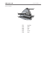
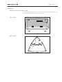
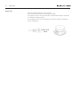
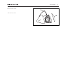
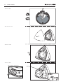
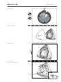
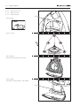
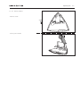
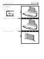
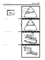
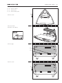
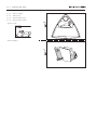
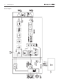
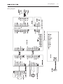
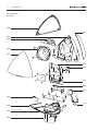
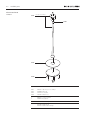
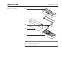
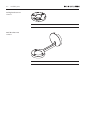
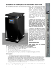
BeoLab 4
Type 6650, 6652
Service Manual
English
German, French, Italian, Spanish, Danish, Dutch and Japanese versions
are available in the Retail System
This Service Manual must be returned with the
defective parts/back-up suitcase !
CONTENTS
Survey of modules ...................................................................... 1.1
How to service ......................................................................... 1.2
Warnings – Insulating test ........................................................ 2.1
Adjustments ............................................................................ 3.1
Repair tips ................................................................................ 4.1
Disassembly ............................................................................. 5.1
Specification guidelines for service use ..................................... 6.1
Block diagram ........................................................................... 7.1
Wiring diagram ........................................................................ 7.2
Available parts ......................................................................... 8.1
Survey of modules
Survey of modules
4
1
2
5
6
3
PCB1
Amplifier
PCB2
SMPS
PCB3
Filter
PCB4
LED
PCB5
Switch
PCB6
Input
1.1
1.2
How to service
How to service
Front line service
BeoLab 4 is to be serviced in the customer’s home when it comes to electrical
symptoms or exchange of mechanical parts. In this way you avoid having to make
more than one visit and using minimum of time on the case, all for the benefit of
the customer.
BeoLab 4 has been split-up into as few service items as possible. Each service friendly
item is packed individually, prepared for worldwide transport, and has a separate
seven digit spare part number to be found in the Bang & Olufsen Retail System or
the Service Manual. The exploded view drawing will show the service spare parts.
Back-up suitcase
A back-up suitcase contains all necessary electrical modules for front-line repair of
one loudspeaker. Cabinet parts must be ordered separately in the Retail System or
directly from B&O Struer DK.
The replaced modules must be returned for repair at Bang & Olufsen, Module
Repair Department. Use the Module Repair form or the form in the Retail Order
System, Exchange Module.
Delivery
As there is only one type number for BeoLab 4, the product can be used for all
markets with 100 to 240 Vac mains voltage. When you order BeoLab 4 (set of
two) this includes two mains cables, two Power Link cables and two boxes with
the three front covers in the chosen colour. This means that the delivery will
consist of four boxes.
This setup allows our packaging department to pack the specific order for the
customer no matter which country it goes to or the colour chosen.
Installation and setting-up
Only the switch for loudspeaker placement and the switch for Left or Right - Line
or PC must be set into correct position as described in the User Guide before
Power Link/Line signal and AC power wires are connected. If the Power Link is
used, the switch is for Left or Right setting. If Line connection is used (via mini-jack
plug) the switch is for Line (0 to 1V) or PC-line (0 to 2V) setting. See more details
in the User Guide. The automatic switch-off circuit is only active with the switch in
Line position, and is not active with the switch in PC-line position.
The LED will indicate on (green) or off (red) only.
Fault Finding
Before troubleshooting is initiated, let the customer demonstrate the fault, if possible.
There are four electrical modules in the product, and furthermore two additional
modules. One with a LED and one with a mini jack socket. Therefore a faulty module
is easy to point out in most cases. The PCB’s has been divided into the functionality:
Inputs, Amplifier, Power supply and Filter.
No special service programs are available in this product or via the ServiceTool.
If there is a fault in the SMPS (PCB2) or Amplifier (PCB1) the LED is typically off.
Only the tweeter unit is protected by a circuit that measures the resistance in the coil,
and will automatically turn down the signal level for the tweeter shortly if it is too
high for a period.
How to service
1.3
Replacement
Replacement of a loudspeaker unit or the amplifier.
Each loudspeaker is individually adjusted from production to secure optimal stereo
perspective.
If a defective loudspeaker unit must be replaced, it is easily done without adjustment
due to the specifications of the unit.
Mechanics
All cabinet parts as e.g. the socket panel can be changed on-site. All surfaces can
be cleaned with a mild detergent.
Internal parts are supplied as service kits, e.g. the loudspeakers, PCB’s etc.
A product cover (soft) for service, black, can be ordered for transport of BeoLab 4.
2.1
Warnings – Insulating test
Warnings
ESD
STATIC ELECTRICITY
MAY DESTROY THE
PRODUCT
When electrical replacements or disassembly is taking place, use an ESD-mat. The
internal electronics are very sensitive to static electricity.
Handling
Wear cotton gloves to avoid any fingerprints on the product.
The surfaces on the product are very sensitive, so handling should be done with
great care to avoid damage.
Cleaning of the speaker surfaces should only be done with a lint-free cloth which
you have dipped in lukewarm water and wrung firmly.
Insulation test
The product must be insulation tested after having been dismantled. Make the test
when the set has been reassembled and is ready to be returned to the customer.
Flashover must not occur during the test.
Make the insulation test as follows:
Short-circuit the two pins of the mains plug and connect them to one of the
terminals of the insulation tester.
Connect the other terminal to ground on the Power Link socket.
NOTE!
To avoid damaging the product it is essential that both terminals of the insulation
tester have good contact.
During the test the current must not exceed 5 mA.
Slowly increase the voltage on the insulation tester until a voltage of 2.5 kV (ac) is
obtained. Maintain the voltage level for one second, then slowly decrease the
voltage to 0 V (ac).
Adjustments
3.1
Adjustments
Adjustments after replacing PCB3 or PCB5
Read out the adjustment position of the old potentiometers, VR601 & VR701, and
set the new potentiometers to the same position.
PCB3 – VR601
VR601
PCB5 – VR701
VR701
4.1
Repair tips
Repair tips
Hum in loudspeaker when no music is played.
The Power Link cable must be of type MK III or higher.
The ground connection in Power Link cable lower than MK III may be insufficient
for optimum sound performance.
The loudspeaker units can be checked by an ohm-meter (tweeter 5.7Ω ±10%;
woofer 6.7Ω ±10%).
Power Link
MK III
Disassembly
Remove front cover
- Pull off front covers
5.1
5.2
Remove woofer
- Remove cables
- Pull off front cover
- Remove screws
4x
TX20
- Remove cables
Do not pull - release lock!
Cables
ESD
PCB xx
ESD-Mat
Remove tweeter
5.3
- Remove cables
- Pull off front cover
- Remove screws
2x
TX20
- Remove cables
Do not pull - release lock!
Cables
ESD
PCB xx
ESD-Mat
5.4
Replace cabinet
☞ 5.1
Remove front cover
☞ 5.2
Remove woofer
☞ 5.3
Remove tweeter
1P301
- Remove plug
ESD
PCB xx
ESD-Mat
- Remove screws
6x
TX20
- Pull off cabinet
Note that this may require some effort
- Remove plug
- Remember to transfer label to new cabinet!
3P612
Replace port
☞ 5.4
Remove cabinet
- Remove screws
2x
- Lift off port as shown
5.5
5.6
Replace PCB1, Amplifier
☞ 5.4
Remove cabinet
☞ 5.5
Remove port
- Remove screws
2x
ESD
PCB xx
ESD-Mat
- Gently pull off bracket with PCB1 mounted
- Remove screws and pull off PCB1
4x
Replace PCB2, SMPS
☞ 5.4
Remove cabinet
- Remove plugs
ESD
2P1
PCB xx
2P2
ESD-Mat
- Remove screws
6x
- Pull off PCB2
5.7
5.8
☞ 5.4
Replace PCB3, Filter
Remove cabinet
3P606
- Remove plugs
2P2
ESD
3P610
PCB xx
ESD-Mat
- Remove screws
6x
- Gently pull off PCB1 and PCB3
- Pull off PCB1
Replace PCB5, Switch
☞ 5.4
Remove cabinet
☞ 5.5
Remove port
☞ 5.8
Remove PCB3, Filter
4x
- Remove screws
- Pull off as shown
(Be aware of the cables!)
ESD
PCB xx
ESD-Mat
- Remove plugs
5P602
5P603
- Remove screws
4x
5.9
5.10
Replace PCB6, Input
☞ 5.4
Remove cabinet
☞ 5.5
Remove port
☞ 5.8
Remove PCB3, Filter
☞ 5.9
Remove PCB5, Switch
1x
- Remove screw
ESD
PCB xx
ESD-Mat
- Remove bracket
1x
Replace bottom plate
☞ 5.4
Remove cabinet
☞ 5.5
Remove port
☞ 5.7
Remove PCB2, SMPS
☞ 5.8
Remove PCB3, Filter
☞ 5.9
Remove PCB5, Switch
☞ 5.10 Remove PCB6, Input
- Remember to transfer label
5.11
5.12
Specification guidelines for service use
6.1
Specification guidelines for service use
Type
Dimensions W x H x D
Weight
Cabinet finish
Power consumption
Voltage
Power amplifier, bass
Power amplifier, treble
Effective Frequency range
Crossover frequency
Cabinet principle
Net volume, bass
Magnetically shielded
Woofer
Tweeter
Bass equalization
Input sensitivity (Power Link)
Input sensitivity (line)
Switch off time (line)
Indicator
Operation
Protection
BeoLab 4
6650, 6652
19.7 x 20.5 x 21.5 cm
1.7 kg
Black, red, blue, dark grey
Typical: 7 W, Stand-by: 0.5 W
100-240 V
35 W, Class D, ICEpower®
35 W, Class D, ICEpower®
50 – 20,000 Hz
3.3 kHz
Bass reflex
1.55 litres
No
101.6 mm (4”), concave diaphragm 6.7W ±10%
19 mm (¾”), fabric dome 5.7W ±10%
ABL (Adaptive Bass Linearization)
125 mV (88 dB SPL)
125 mV (88 dB SPL) - Auto switch on
3 min.
LED for on (green) or off (red)
Free, Wall or Corner position
Left, Right or LINE, PC switch
Thermal protection of tweeter and SMPS
Power Link
Mini-jack (line-in)
1 (use semi-balanced PL cable type MK III, or fully mounted PL cable)
Via mini-jack plug 0-1 V (Line - automatic on/off) or 0-2 V
(PC - always on) selected by switch
Accessories
Ceiling bracket, type 2177 Floor stand, type 2178 Wall bracket, type 2179 1217711 (a pair)
1217811 (a pair)
1217911 (a pair)
Cable mini-jack stereo to 2 x mini-jack mono (L and R), 2.5 m
Cable RCA/mini-jack mono, 5 m, black
Power Link splitter (one male to two female PL plugs)
6270250 black
6270273 (a pair)
6270706
Subject to change without notice
7.1
Block diagram
VR601
VR701
Block diagram
Wiring diagram
Wiring diagram
7.2
8.1
Available parts
Available parts
BeoLab 4
9001
9001
9002
9003
1
1
1
2
9004
1
2
9001
2
1
1
9009
3
3
3
5
1
9010
4
4
4
3
3
5
9011
5
5
9012
5
3
3
3
2
9005
9008
3
3
3
3
3
3
6
9014
9006
9007
9013
3
6
Incl. pos. no. 9006
7
Available parts
BeoLab 4
9001
9006
9007
9008
9009
9010
9011
9012
9013
9014
1604244
1604246
1604248
1604249
3430049
8480048
8480049
6100273
6100329
6100307
6100332
6100386
6100331
6100047
3340293
3454102
3390066
3358148
3340291
3131096
3340290
3458134
3340292
1Module
8002619 PCB1, Amplifier
2Module
8002620 PCB2, SMPS
3Module
8002621 PCB3, Filter
4Module
8002622 PCB4, LED
5Module
8002623 PCB5, Switch
6Module
8002624 PCB6, Input
1
2
3
4
5
6
7
2011006
2011008
2011009
2011013
2011012
2011011
2011010
9002
9003
9004
9005
Survey of screws etc.
Front cover, red
Front cover, black
Front cover, blue
Front cover, dark grey
Cabinet
Tweeter
Woofer
Mains cable, EU
Mains cable, UK
Mains cable, US
Mains cable, AUS
Mains cable, KOR
Mains cable, JP
Mains cable, CHN
Gasket
Bottom incl. pos. no. 9006
Bag w/parts
Heat zink
Gasket
Housing
Gasket
Port
Gasket
Screw 4 x 10mm
Screw 4 x 10mm
Screw 3 x 8mm
Screw 2.6 x 8mm
Screw 2.6 x 8mm
Screw 3 x 6mm
Screw 3 x 6mm
Wire bundle
6277995 Wire f/speakers
Parts not shown
3395297
3375491
6270250
6270273
3375590
Packing
3392894 Packing, complete
Available documentation
Back-up suitcase
Product cover
Cable mini-jack stereo
Cable RCA/mini jack
Autosol chrom polishing
See Retail Ordering System
8.2
8.3
Available parts
Floor Stand 2178
1217811
1
9101
Incl. pos. nos. 9102, 1
2
2
2
9102
9103
9104
2
9101
9102
9103
9104
3932011
2369004
3162238
3103392
Tube incl. pos. nos. 9102, 1
Cable clip
Cover plate
Rubber foot
1
2
2046017 Screw 6 x 16mm
3390078 Bag w/parts
3390082 Cable manager
3507402 Guide f/2178
3507662 Guide f/cable manager
Available parts
Packing – Floor Stand
9301
9302
9303
9301
9301
9302
9303
3396330 Foam packing, set
3016012 Guide f/cover plate
3392486 Outer carton
8.4
8.5
Available parts
Ceiling bracket 2177
1217711
3507401 Guide
Wall bracket 2179
1217911
3507403 Guide
Bang & Olufsen
DK-7600 Struer
Denmark
Phone +45 96 84 11 22*
Fax +45 97 85 39 11
3538032 12-06 A