1
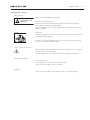
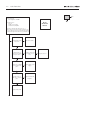
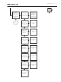
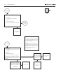
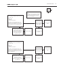
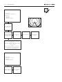
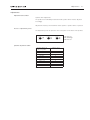
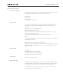
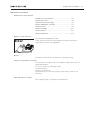
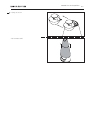
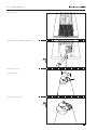
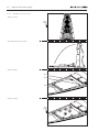
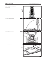
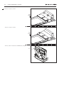
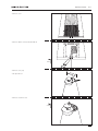
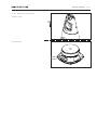
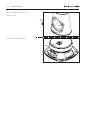
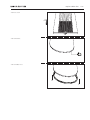
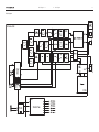
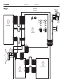
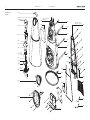
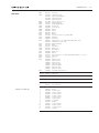
BeoLab 9
Type 6217
Service Manual
English
German, French, Italian, Spanish, Danish, Dutch and Japanese versions
are available in the Retail System
This Service Manual must be returned
with the defective parts/back-up suitcase !
CONTENTS
Survey of modules ..................................................................... 1.1
How to service ........................................................................... 1.2
Fault flow chart ......................................................................... 2.1
Adjustments .............................................................................. 3.1
Repair tips ................................................................................. 3.2
Final check after repair . ............................................................. 3.3
Replacement of modules ........................................................... 4.1
Specification guidelines for service use ....................................... 5.1
Block diagram . .......................................................................... 6.1
Wiring diagram . ........................................................................ 6.3
Available parts ........................................................................... 7.1
Survey of modules
1.
Survey of modules
3
4
7
999
PCB1
PCB2
PCB3
PCB4
PCB5
PCB7
999Module
Cross Over
LC-Filter
LED
Power Supply
ICEpower Amplifier
NTC
Chassis complete, incl. PCB1, PCB2, PCB5
1.
How to service
How to service
Strategy
BeoLab 9 has been split-up into as few service items as possible. Each servicefriendly item is packed individually, prepared for worldwide transport, and has a
separate seven digit spare part number to be found in the Bang & Olufsen Retail
System or the Service Manual. An exploded view drawing shows the service spare
parts.
The back-up suitcase holds all necessary electrical modules for front-line repair of
one loudspeaker in e.g. the customers home.
Cabinet parts must be brought with you separately, if to be replaced in the
customers home.
1.
2.
3.
4.
An adequate fault description must be returned with each replaced part. For this
purpose, use the Module Repair form or the form in the Retail Order System under
Exchange Module. To help the Bang & Olufsen Module Repair department it is
very important to answer the following questions:
Which products are in the setup?
Which software versions are used in these products?
How are the products linked together?
What happens in the actual situation?
All service repair will be on module level by means of the back-up suitcase.
Service Manuals in other languages can be found in the Retail System as PDF-files.
Preparations before service
Always remember to download the latest version of the Service Manual.
Fault description must be returned with the replaced parts.
Use the Module Repair form or the form in the Retail Order System, Exchange
Module.
Fault explanation and demonstration
Before troubleshooting is initiated, let the customer demonstrate the fault, if
possible.
Recommended tools for service
White gloves.
Soft lint-free cloth.
Multimeter.
How to service
1.
Handling and cleaning
Static electricity
Static electricity may damage the product.
STATICELECTRICITY
MAYDESTROYTHE
PRODUCT
Static-protective field service kit.
A static-protective field service kit must always be used when the product is
disassembled or modules are being handled.
Follow the instructions in this Service Manual and use the ESD-mat for both old
and new modules.
Please note:
When mains voltage on the product is required, remove the connection between
the product and the ESD-mat.
ESD
The chassis or modules must always be connected to the static-protective field
service kit or placed in an ESD-proof bag.
Symbol of safety components
When replacing components with this symbol, the same type has to be used, also
the same values for ohm and watt.
The new component is to be mounted in the same way as the replaced one.
Transport and handling
-
-
It is recommended to:
use the product cover when transporting the product.
do not move the product when it is operating.
Cleaning
Please refer to the chapter “Final check after repair” or the User’s guides.
1.
Fault flow chart
Fault flow chart
No red light in STANDBY . .....................................................
No sound, but green LED is OK . ...........................................
No sound from woofer, but tweeter and midrange is OK ......
No sound from midrange, but tweeter and woofer is OK ......
No sound from tweeter, but midrange and woofer is OK ......
No function of the PCB7, NTC ..............................................
No function of S1 and S2 .....................................................
2.2
2.4
2.4
2.5
2.5
2.6
2.6
2.
2.
Fault flow chart
No
Fault symptom:
- No red light in STANDBY
Note:
Ground is
chassis
Possible causes:
- Fuse F1
- PCB4, Power Supply
- Module 999, Amplifier
Connect a Master Link cable from e.g. a
BeoSound 4, to BeoLab 9. Make sure that S101
is set to either L or R. Connect mains to BeoLab 9.
Is there red light in the LED on top of BeoLab 9?
Confirm mains in the
mains wire
Reconnect mains
Confirm mains on
PCB4, Power Supply
P13 pin1 and 2
If possible, check fuse
F1 on PCB1, Cross
Over
Confirm 5V on PCB4,
Power Supply P14
pin1
Replace PCB4, Power
Supply
Confirm 4.2V on
PCB1, Cross Over P9
pin 2
Replace Module 999,
Amplifier
Replace PCB3, LED
Replace fuse F1
Yes
Fault flow chart
No
Select e.g. Radio or
CD on the
Audiomaster, and
press GO on Beo4
Does BeoLab 9 turn
on (Green light in
LED)
Go to
next page
Confirm 5V on PCB4,
Power Supply P14 pin
7
Check Power Link
cable and
Audiomaster.
Reconnect/replace if
nescessarry.
(This is not covered in
this fault flow chart)
Confirm -12V on
PCB4, Power Supply
P14 pin 3
Replace PCB4, Power
Supply
Confirm 12V on
PCB4, Power Supply
P14 pin 5
Replace PCB4, Power
Supply
Confirm 44V on PCB4,
Power Supply P15
pin 4
Replace PCB4, Power
Supply
Confirm -44V on
PCB4, Power Supply
P15 pin 5
Replace PCB4, Power
Supply
Confirm 66V on
PCB4, Power Supply
P15 pin 6
Replace PCB4, Power
Supply
Confirm approx 4.7V
on PCB4, Power
Supply P14 pin 9
Replace PCB4, Power
Supply
Replace Module 999,
Amplifier
Yes
2.
2.
Fault flow chart
No
From previous
page
Yes
Fault symptom:
- No sound, but green LED is OK
Possible causes:
- Module 999, Amplifier
Is there no sound, but the green LED is OK?
Go to box
further down
on page
Replace Module 999,
Amplifier
Note:
It wil give the best result if it is possible to
use an audio test CD with pure sine waves
and an oscilloscope, when measuring on
the woofer or midrange.
From above
Fault symptom:
- No sound from woofer, but tweeter and
midrange is OK
Warning:
Be very careful, when measuring on the
woofer, because there is approx 35Vdc on
both input terminals. Make sure to use a
differential probe, or make sure that the
oscilloscope and the product is not
connected to earth.
Possible cause:
- Woofer
- Module 999, Amplifier
Visual confirm cable
connection between
woofer and Module
999, Amplifier
Turn volume on the Audio Master up to 50.
Confirm an AC-Sound signal by means of the
Bar-graph on the multimeter or an oscilloscope,
when measuring across the woofer input
terminals.
Remove mains from the
product. Remove the black wire
from the woofer. Measure the
resistance across the woofer
terminals:
Approx 2.9 ohm?
Replace woofer
Replace Module 999,
Amplifier
Reconnect/replace
cable
Fault flow chart
No
Fault symtom:
- No sound from midrange, but tweeter and
woofer is OK
Note:
It wil give the best result if it is possible to
use a audio test CD with pure sine waves
and an oscilloscope, when measuring on
the woofer or midrange
Yes
Possible cause:
- Midrange
- Module 999, Amplifier
Visual confirm cable
connection between
midrange and Module
999, Amplifier
Turn volume on the Audio Master up to 50.
Confirm an AC-Sound signal by means of the
Bar-graph on the multimeter or an oscilloscope,
when measuring across the midrange input
terminals.
Remove mains from the
product. Remove the black
wire from the midrange.
Measure the resistance across
the midrange terminals:
Approx 6.1 ohm?
Replace midrange
Reconnect/replace
cable
Replace Module 999,
Amplifier
Fault symtom:
- No sound from tweeter, but midrange and
woofer is OK
Possible cause:
- Tweeter
- Module 999, Amplifier
Visual confirm cable
connection between
tweeter and Module
999, Amplifier
Turn volume on the Audio Master up to 50.
Confirm an AC-Sound signal by means of the
Bar-graph on the multimeter or an oscilloscope,
when measuring between PCB1, Cross Over
P10 pin 1 and ground.
Remove mains from the
product. Remove the connector
on PCB1, Cross Over P10.
Measure the resistance
between the orange and white
wire:
Approx 6.6 ohm?
Replace tweeter
Replace Module 999,
Amplifier
Reconnect/replace
cable
2.
2.
Fault flow chart
No
Fault symptom:
- No function of the PCB7, NTC
Possible cause:
- PCB7, NTC
- Cable W4
- Module 999, Amplifier
Yes
Fig1
Red
Black
Is the loudspeaker in
protection mode?
Visual confirm cable
connection between
Module 999, Amplifier
and PCB7, NTC
Reconnect/replace
cable
To confirm correct operation of the NTC, measure
approx. 9.35V DC at normal room temperature, as
shown in fig 1
(When the temperature is rising, the DC voltage is
going towards 0)
Note:
When the loudspeaker goes into protection mode,
it is nescessarry to disconnect mains and wait one
minute before connecting it again.
Fault symptom:
- No function of S1 and S2
Possible cause:
- Module 999, Amplifier
Is there no function of
switch S1 and/or S2?
Replace Module 999,
Amplifier
Replace PCB7, NTC
Replace Module 999,
Amplifier
Adjustments
3.1
Adjustments
Adjustments described
Speaker driver adjustment.
The speakers are individually measured and the speaker driver must be adjusted
accordingly.
Adjustment must be performed when either speaker or speaker driver is replaced.
Access to adjustment points
The adjustment points are placed on the socket panel on the back of the product.
456
456
23
23
456
23
1
9 01
9
78
+
WO
78
+
MR
0
9 01
TW
78
+
Speaker adjustment table
Speaker value from
label on speaker
1.8 – 2.3
1.3 – 1.7
0.8 – 1.2
0.3 – 0.7
-0.2 – 0.2
-0.3 – -0.7
-0.8 – -1.2
-1.3 – -1.7
-1.8 – -2.2
-2.3 – -2.5
Switch position
0
1
2
3
4
5
6
7
8
9
TW: Tweeter
MR: Midrange
WO: Woofer
3.2
Repair tips
Repair tips
Hum in speaker when no music is played
The Power Link cable must be of type MK III or higher.
Power Link
MK III
The ground connection in Power Link cable lower than MK III may be insufficient
for optimum sound performance.
Standby LED
The standby LED indicates the status of the BeoLab 9.
Standby LED STATUS
Red
BeoLab 9 is in standby.
Green
BeoLab 9 is operating.
Orange
BeoLab 9 is shut down due to thermal overload.
If the LED Status is orange, turn off and disconnect the product from the mains.
Wait for minimum 5 minutes for the speaker to cool down.
Connect mains and turn on BeoLab 9.
If the LED status still is orange the fault may be due to:
1. Woofer protection – perform speaker check.
2. Tweeter protection – perform speaker check.
3. Midrange protection – perform speaker check.
4. NTC-board or connection on one of the woofers.
Access the NTC-board by dismantling the woofer.
4. Power supply failure.
Final check after repair
3.3
Final check after repair
Final check after repair
The final check after repair describes the activities that are needed to ensure the
product will be returned in perfect condition to the customer.
The content is:
– Insulation test.
– Restore setup.
– Final cleaning of the product.
Insulation test
The product must be insulation tested after having been dismantled. Make the
test when the set has been reassembled and is ready to be returned to the
customer.
Flashover must not occur during the test.
Make the insulation test as follows:
Short-circuit the two pins of the mains plug and connect them to one of the
terminals of the insulation tester.
Connect the other terminal to ground on the Power Link socket.
NOTE!
To avoid damaging the product it is essential that both terminals of the insulation
tester have good contact.
During the test the current must not exceed 5 mA.
Slowly increase the voltage on the insulation tester until a voltage of 2.5 kV (ac) is
obtained. Maintain the voltage level for one second, then slowly decrease the
voltage to 0 V (ac).
Restore setup
Ensure that,
– The F/W/C switch is in correct position.
– The plug is inserted over the standby LED.
– The Power Link cable is a MK III or higher.
Check sound
Ensure that all speakers are OK.
Clean the product
Clean dusty surfaces using a dry soft cloth. If necessary, remove grease stains or
persistent dirt with a lint-free, firmly wrung cloth, dipped in a solution of water
containing only a few drops of mild detergent such as washing-up liquid.
The loudspeaker front grill may be cleaned with a vacuum cleaner with a soft
brush nozzle, and set to the lowest level.
3.4
Replacement of modules
Replacement of modules
Modules that can be replaced
BeoLab 9 in service position ........................................ 4.2
Replace PCB3, LED ..................................................... 4.4
Replace PCB4, Power Supply ...................................... 4.6
Replace 999Module, Amplifier . .................................. 4.7
Replace tweeter . ........................................................ 4.9
Replace midrange ..................................................... 4.11
Replace woofer ........................................................ 4.12
Replace rubber foot .................................................. 4.13
Warning – Static electricity
Static electricity may damage the product.
A static-protective field service kit must always be used when the product is
disassembled or modules are being handled.
ESD
ESD-Mat
Notice!
All modules must be placed on the ESD-mat or in an ESD-proof bag.
Purpose of replacement of modules
Short instructions for replacement of the available modules, with reference to
additional illustrations:
- The correct sequence for replacing modules.
- Text and illustrations.
- Reference to adjustment.
Modules that do not require any special procedure may be shown as only
illustrations.
After replacement of drivers
After replacing a driver, see Adjustments and Repair tips.
4.
4.
BeoLab 9 in service position
- Remove cover
- Remove cables connected to BeoLab 9
2x
3mm
- Remove cover, top
- Use Special tool
- Remove screws for lens
3x
2.5mm
BeoLab 9 in service position
- Gently lift off lens
- Pull off fabric frame
4.
4.
Replace PCB3, LED
- Remove cover
- Remove cables connected to BeoLab 9
2x
3mm
- Remove cover, top
- Use Special tool
- Remove screws for lens
3x
2.5mm
Replace PCB3, LED
- Gently lift off lens
- Remove screws and pull of lens top
Remove cable
3P25
3x
TX20
1
2
3
- Remove screws and pull off PCB3, LED with chassis
4x
TX10
- Remove screws for PCB3, LED
3x
TX10
4.
4.
Replace PCB4, Power Supply
+ 4.2 BeoLab 9 in service position
- Remove screws
12x
TX20
- Flip down heat sink as shown
- Remove cables
4P15
4P14
4P13
- Remove screws
9x
TX10
Replace 999Module, Amplifier
+ 4.2 BeoLab 9 in service position
- Remove screws
12x
TX20
- Flip down heat sink as shown
- Remove cables from woofer
- Remove cables as shown
1P10
1P9
4P15
4P14
4.
4.
Replace 999Module, Amplifier
- Remove screws as shown
3x
TX20
- Remove screws as shown
3x
TX10
- Remove cable on backside of 999Module, Amplifier
1P2
Replace tweeter
- Remove cover
- Remove cables connected to BeoLab 9
2x
3mm
- Remove cover, top
- Use Special tool
- Remove screws for lens
3x
2.5mm
4.
4.10
Replace tweeter
- Gently lift off lens
- Remove screws and pull of lens top
Remove cable
3P25
3x
TX20
1
2
3
- Remove tweeter cover
- Remove screws for tweeter
3x
TX10
Replace midrange
+ 4.2 BeoLab 9 in service position
- Remove screws
4x
TX20
- Remove cables
4.11
4.12
Replace woofer
+ 4.2 BeoLab 9 in service position
- Remove screws
4x
TX20
- Remove cables (remember NTC)
Replace rubber foot
- Remove screw
1x
TX10
- Pull off bracket
- Pull off rubber foot
4.13
4.14
Specification guidelines for service use
Specification guidelines for service use
BeoLab 9
Type number
6217
5.
Dimensions W x H x D
775mm x 400mm x 300mm
Dimensions W x H x D, incl. packaging two pcs. in one carton box1004mm x 800mm x 600mm
Weight16.6 kg
Weight, incl. packaging
44.9 kg
Cabinet finish
Black cloth, aluminium
Blue cloth, aluminium
Dark grey cloth, aluminium
Red cloth, aluminium
Mains
90-240Vac
Power consumption
65W (IEC60065)
25W typical
< 0,5W in standby
Power amplifier, bass
400W, 4 ohm, class D ICEpower
Power amplifier, midrange100W, 6 ohm, class AB
Power amplifier, treble100W, 8 ohm, class AB
Effective Frequency range
30 - 20,000 Hz
Crossover frequency180/2000 Hz
Cabinet principle
Closed box
Net volume, bass18 litres
Net volume, midrange
4 litres
Woofer10” / 250mm cone
Midrange
5” / 125mm cone
Tweeter
3/4” / 19mm dome in acoustic lens
Bass equalization
ABL (Adaptive Bass Linearization)
Input sensitivity (Power Link) and (line)125mV @ 91dB SPL
Switch off time (line)
Automatic on /off (up to 3min)
Indication
On/Off LED placed in the acoustic lens
Operation
Switch for Free standing - Against wall - In corner
Switch for Left - Right - Line (via PL plug)
Protection
Thermal protection of all drivers
ABL system protects the bass unit against mechanical damage
Connections
Power Link
Two (use semi-balanced PL cable type MKIII, or fully mounted PL cable)
POWER LINK
Pin 1
Pin 2 Pin 3
Pin 4
Pin 5
Pin 6
Pin 7
Pin 8
Line-in
Mains
Via PL using Line-to-PL adaptor cable
Subject to change without notice
PL ON => 2.5V, OFF = < 0.5V
Signal GND
Audio L out 0V - 6.5V RMS
PL speaker ON => 2.5V, OFF = < 0.5V
Audio R out 0V - 6.5V RMS
Data: High > 3.5V, Low < 0.8V
Data GND
Not used
One (two pin male shaver plug type)
5.
Block diagram
6.1
6.1
Block diagram
6.1
Block diagram
Module 999
PCB5
PCB4
6.2
6.2
6.2
Wiring diagram
6.3
6.3
Wiring diagram
6.3
Module 999
Amplifier
Tweeter + Lens
4
>
>
>
>
>
>
<
<
>
>
>
>
>
>
LED
<
<
>
JST VH
JST VH
<
<
1
W2
8 ohm
>
Midrange
>
>
>
>
JST 2mm
>
>
>
>
>
>
JST SDN
Soldered into PCB
Molex MLX
Cross Over
>
>
Micro-Match
Soldered into PCB
>
>
>
>
>
>
>
>
W4
7
W5
>
<
W6
>
>
>
>
<
>
>
>
>
<
>
>
>
>
JST PH
JST SAN
Soldered into PCB
Micro-Match
W7
LC-Filter
>
>
<
<
>
>
<
<
<
<
>
>
<
<
>
>
5
ICE-Power Amplifier
Molex Micro-Fit
2
JST SDN
Soldered into PCB
>
>
JST VH
>
>
>
>
>
>
>
>
>
>
<
Woofer
JST XA
JST 2mm
W3
4 ohm
3
W1
Power Supply
NTC
8 ohm
>
Micro-Match
Soldered into PCB
Micro-Match
W9
>
>
W8
>
>
>
>
7.1
Available parts
BeoLab 9
Available parts
7.1
7.1
Available parts
9001
9
9002
9003
Incl. pos. no. 1
9015
Incl. pos. nos. 9016, 9017,
9020, 9021, 9, 10
9
9
10
10
9017
1
9004
9016
1
2
10
10
6
10
10
6
9017
9005
6
3
9006
3
10
10
3
3
6
9017
6
10
9007
10
9008
9017
6
3
3
6
3
10
10
Incl. pos.
no. 9008
9017
6
6
9018
9010
9
3
9011
9018
9004
9012
9023
9017
2
2
3
9009
Incl. pos. nos. 9018, 9019,
9022, 9024, 3, 4, 11, 9, 13
4
*
4
4
Incl. pos. nos.
9010, 9011
9019*
10
9020
5
6
5
9
4
4
9
6
*
13
11
11
6
9013
6
6
3
*
9021
5
9
6
9024
13
9025
9022
6
11
7
6
8
7
11
11
11
4
6
9014
6
6
6
999
3
3
6
6
6
11
11
11
11
*
9026
11
9027
12
12
3
12
Incl. pos. no. 9022
Available parts 7.2
BeoLab 9
Survey of screws etc.
9001
9002
9003
9004
9005
9006
9007
9008
9009
9010
9011
9012
9013
9014
9015
9016
9017
9018
9019
9020
9021
9022
9023
9024
9025
9026
9027
3458152
3321047
3321048
3321049
3321050
3131109
3332007
3152321
3912009
3459508
3947303
8480084
3947306
3947318
3131108
8480080
8480082
3400061
3947350
3332010
3151911
3152235
3947305
3152154
2954004
3947304
3358277
3151552
3160408
6100273
6100329
6100307
6100332
6100386
6100331
6100047
6270688
Cover, top
Fabric frame, black
Fabric frame, dark grey
Fabric frame, blue
Fabric frame, red
Lens, top incl. pos. no. 1
Damping material
Chassis w/light guide
Acoustic felt
Cover, tweeter
Gasket
Tweeter
Gasket
Gasket
Lens, bottom incl pos. nos. 9010, 9011
Midrange
Woofer 10”
Cabinet incl. pos. nos. 9016, 9017, 9020, 9021, 9, 10
Tape/foam 3 x 7mm – 10m
Damping material
Guide
Clips f/wire
Gasket, set
Bracket f/foot
Rubber foot
Gasket
Heat sink incl. pos. nos. 9018, 9019, 9022, 9024, 3, 4, 11, 9, 13
Wire holder
Cover
Mains wire, EU
Mains wire, UK
Mains wire, US
Mains wire, AUS
Mains wire, KOR
Mains wire, JPN
Mains wire, CHN
Powerlink cable, black, 5m
3Module 8003276
PCB3, LED
4Module 8003325
PCB4, Power Supply
7Module 8100090
PCB7, NTC
999Module8052273
F1
6600177
999Module, Amplifier consists of: PCB1 - PCB2 - PCB5, incl. pos. no. 9022
Fuse T 5A 250V
1
2
3
4
5
6
7
8
9
10
11
12
13
Gasket
Screw 3 x8 mm
Screw 3 x 10mm
Screw 4 x 10mm
Screw 4 x 12mm
Screw 4 x 12mm
Screw 3 x 8mm
Lock washer
Bushing
Screw 3 x 10mm
Screw 3 x 10mm
Screw 4 x 55mm
Solder pin
2930112
2052040
2054060
2058092
2019025
2019021
2058026
2625002
2930178
2052011
2054043
2015005
7530118
7.3 Available parts
Wire bundles
W2
6277985
Wire from PCB1, P2 – PCB4, P13
Parts not shown
3395313
3376000
3040017
Back-up suitcase
Product cover
Special tool
Accessories
6270856
6270433
Cable, RCA-phono to PL Line-in, black, 5m
Adapter, mini-jack/male – RCA female x 2
Packing
3393016
3396425
3392768
Outer carton, top-bottom
Packing, complete
Pallet
Available documentation
See Retail Ordering System
Bang & Olufsen
DK-7600 Struer
Denmark
Phone +45 96 84 11 22*
Fax +45 97 85 39 11
3538063
02-07