1
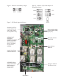
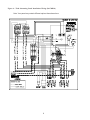
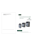
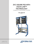
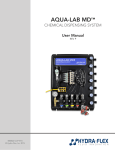
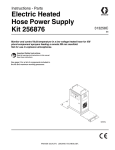
SEWER SYSTEMS
T260
Alternating
Panel
Service
Information
Environment One Corporation
Contents
Panel Basics ......................................................................................................................................... 3
Panel Operation .............................................................................................................................. 3
High-Level Alarm Operation .......................................................................................................... 3
Manual Run Operation ................................................................................................................... 3
Both-Pump Operation (AUTO/BOTH Switch) ................................................................................ 3
Changing Alternating Time (NORMAL/TEST Switch & Alternator Cycle Time Jumpers) ............ 3
System Status LED Operation ........................................................................................................ 4
Alarm Dry Contact ......................................................................................................................... 4
Alarm Dry Contact Servicing Note ................................................................................................ 4
Startup Procedures .............................................................................................................................. 5
Troubleshooting ................................................................................................................................... 7
Figures
Figure 1 - Nuisance Alarm Delay Jumper ........................................................................................................... 8
Figure 2 - Alternate Cycle Time Jumper & Normal/Fast Switch ........................................................................ 8
Figure 3 - PC Board Operation Picture ............................................................................................................... 8
Figure 4 - T260 Alternating Panel Installation Wiring (PA1788P01) ................................................................... 9
1
Panel Basics
Service Safety: Only people trained in electrical safety and on Environment One
equipment should work on these controls.
Anytime the panel or pump is serviced, the power must be turned off, including the power used
on the dry contact (which is a separate power supply in many cases). Never make any changes
on the alarm/alternating PC board unless the power is off. Failure to turn off power could cause
personal harm as well as possible damage to the equipment.
Panel Operation
At any given time, only one pump has full line voltage going to it; this is the lead pump. The lead
pump operates off its own controls and remains the lead pump for a set amount of time (24
hours is the factory preset standard default). Per the factory default, the panel will switch the
power from the lead to the lag pump every 24 hours. Pump 1 will be on, or lead, for 24 hours,
then Pump 2 for 24 hours, then back to Pump 1 for 24 hours, and so on.
High-Level Alarm Operation
Both pumps have high-level alarm pressure switches; if either alarm switch closes, the circuit
will go into alarm mode. During the alarm mode, the panel will apply power to both pumps and
delay the alarm light and horn 3.5 minutes. This delay is to prevent nuisance alarms in the event
of an unusually high flow. If the station is still in high-level alarm after the delay, the light and horn
will activate. To silence the horn, push the button located at the lower left-hand corner outside
the panel box. The alarm will clear once both alarm switches in the pumps open (or clear). The
delay on the alarm may be eliminated by moving jumper on J2 to the right two pins (Figure 1).
Manual Run Operation
Two manual-run rocker switches are located on the PC board above the lower terminal blocks.
The lead, or powered, pump will run while its rocker switch is depressed. The yellow LED’s,
located in the middle of the PC board, indicate which pump is powered.
Both-Pump Operation (AUTO/BOTH Switch)
To run both pumps simultaneously, slide the AUTO/BOTH switch, located in the middle of the
board, down; this will energize both contactors in the panel and supply power to both pumps all
the time. The pumps will operate automatically and independently as the water level in the tank
rises. You will see both yellow LED’s are on with the slide switch in this position. Either or both
manual-run switches will run its corresponding pump. Slide the switch up to put the panel back
to AUTO for normal operation.
This feature is also used when Pump 1 or Pump 2 is not in use. When the AUTO/BOTH switch
is down in the BOTH position, contactors 1 and 2 will be energized. If either of the pump breakers
is turned off, the other pump will remain energized until the switch is moved to AUTO.
Changing Alternating Time (NORMAL/TEST Switch & Alternator
Cycle Time Jumpers)
Service Safety: Always turn all power off (including power to dry contact) before
servicing or making any changes on the PC board.
2
Located on the top left-hand side of the PC board is a series of pairs of pins (position J1 on the
board). By selecting different pins with the jumper block, the time the panel takes to alternate
from one core to the next will change. The first two pins to the left are to be selected, using the
jumper block, to have the panel alternate every 8 days, the next set in is 4 days, then 2 days,
then 1 day and finally 3 hours. In Figure 3, the jumper is on the 3-hour setting. The factory sets
the jumper block at the 1-day position, which is the second set of pins from the right, or the
fourth set from the left.
To test the PC board to ensure the operation, move the jumper to the 3-hour position and slide
the NORMAL/FAST switch to the FAST position. Turn on the power to the alarm PC board and
both cores. The panel should energize Contactor 2 first, and in 3 to 4 minutes it should switch
to Contactor 1. The panel will switch between Contactors 1 and 2 every 3 to 4 minutes. When
the test is complete, turn off all power, switch back to the NORMAL position, and select the
proper jumper position for the time you need to alternate between the two cores. Turn on the
power.
System Status LED Operation
Six LED’s are located on the control board. See Figure 3 for the location of each LED.
RED: Two red LED’s are located in the center of the PC board. These lights indicate the alarm
status of the station. Each pump has its own light.
GREEN: Two green LED’s are located just above center on the PC board. They light when its
pump is running.
YELLOW: Two yellow LED’s are located just below center on the PC board. They indicate
which pump is the lead, or powered, pump. The lag LED will be dimly lit (about ¼ bright).
Alarm Dry Contact
The dry contact is located on the PC board, at the bottom, lower left-hand corner. This connection
is used when an auxiliary (secondary) alarm is needed. Power is fed to the one terminal; the
other terminal is the return, which goes to the device you want to energize when the station
goes into alarm.
If the panel has four similar relays populated on the PC board, it is equipped with a standard dry
contact feature. The contacts can only operate if power is going to the PC board.
If the panel has six similar relays populated on the PC board, it is equipped with the option for
dry contact to operate as a Power Loss High Level Alarm. If the power fails and the station fills
to the high level, the contact will close, completing the circuit to your alarm device. This feature
would need a battery-supplied circuit to operate. This feature is meant to be used with 24-volt
devices and lower. Environment One recommends the E/One Sentry Unit with this feature.
Alarm Dry Contact Servicing Note
The power must be disconnected from the dry contact when any service work is performed on
the panel, the pump or the station. The breakers in the panel have no control over the power to
the dry contact.
3
Startup Procedures
The control panel should be operationally tested once the installation is complete and before
the station is to go online. Failure to due so could cause damage to the product.
1. Double check all wire connections in the panel, including the incoming power to the breakers
and the pump leads. Follow the wiring pictorial on the panel door for proper placement of
wires.
NOTE: All panels may not be wired the same due to additional options and/or factory changes.
Always refer to wiring diagram inside of panel door for correct wiring.
2. Check incoming power to ensure that the phases at the breakers match the panel wiring
pictorial on the panel door. Also check to see that the pump leads are grouped together.
3. Check the power source coming to the panel. The voltage must be within 10 percent of the
voltage listed on the panel nameplate (216 to 264 for 240V USA). If the voltage is low, you
must install a transformer to adjust it within these limits, or the station will not run properly
and may cause equipment damage.
4. Perform a short test to each core per service manual startup procedures. Table 1 shows
the readings you should get when checking resistance between the wires coming from
each core. Set your meter according to the chart below. If readings taken are not close to
the readings given, troubleshoot the supply cable and pump core for the cause.
Table 1 assumes the station is dry, or at least below the turn-on level of the pump cores. (For
USA, 240V pumps only; refer to your regional service maual for correct values.)
Wire 1
Wire 2
Meter Scale
Correct Reading
Black
Red
2000K ohm or 2 meg ohm
15 k
White
Red
200K ohm
1.5 k
Green
Black, White, Red
2000K ohm or 2 meg ohm
Open, no reading
Table 2 assumes the station is full, above the pump cores’ alarm level. (For USA, 240V pumps
only; refer to your regional service maual for correct values.)
Wire 1
Wire 2
Meter Scale
Correct Reading
Black
Red
2000K ohm or 2 meg ohm
White
Red
200K ohm
Orange
Blue
2000K ohm or 2 meg ohm
0 (alarm sw. closed)
2000K ohm or 2 meg ohm
Open, no reading
Green
Black, White, Red
4
0
1.5 k
5. Open all discharge valves in the system.
6. Turn on the single-pole control/alarm circuit breaker, located on the right-hand side of the
group of breakers. A yellow light should illuminate on the control board; if not, check the
voltage between the top of the breaker and the neutral terminal in the terminal block. The
voltage should read within 10 percent of 1 leg of power.
7. Fill the tank with water until the alarm turns on. Remember, there is a 3.5-minute delay
between the alarm closure and the panel alarm. Push the silence switch located under the
panel on the left-hand side.
8. Turn off the breakers in the panel. In the center of the PC board, there is a slide switch that
changes the panel from AUTO operation to BOTH pump operation. See Figure 1 for the
location of this switch. Slide the switch down to select both. Turn on the alarm breaker.
9. Connect an amp probe to the white lead going to Pump 1. Turn on the breaker for Pump 1.
The amperage should be between 5 and 8 amps. The green LED for Pump 1 should
illuminate.
10. Once the pump one runs down and turns off, connect the amp probes on the white wire for
Pump 2. Turn off the breaker for Pump 1 and turn on the breaker for Pump 2 and run water
into the tank until it turns on. The amperage should be between 5 and 8 amps. The green
LED for Pump 2 should illuminate.
11. Turn off all breakers. Slide the AUTO/BOTH switch up to the AUTO position.
12. Turn on all breakers.
13. Log the serial number, voltage and amperage of each pump while it is running.
PUMP ONE
Serial # ______________ Voltage ___________ Amperage __________
PUMP TWO
Serial # ______________ Voltage ___________ Amperage __________
5
Troubleshooting
DANGER! VOLTAGE KILLS! Always turn off all power, including the power to the dry
contacts, while working in the control panel. Only people trained in electrical safety
and on Environment One equipment should work on these controls.
NOTE:If the alternating controller fails to operate and the pumps appear good, the pumps can
be wired directly to the breakers. Disconnect the black and white pump wires from the contactors
and connect them to the output side (top side) of the pump breakers. Ensure that the singlepole control/alarm breaker remains off. Once the pump breakers are turned on, the pumps
will operate independently. This is a temporary fix while waiting for parts.
Always check first that the connections within the panel are properly connected.
1. No LED’s light on the control board after the single-pole control/alarm breaker is turned on.
Ensure that the voltage between the top of the single-pole control/alarm breaker and the neutral
terminal block is within 10 percent of 1-leg of power. Check the incoming power at the bottom of
the breaker and neutral. If there is no or low power, check between L1 and L2; the voltage
should be within 10 percent of the voltage listed on the panel nameplate. If not, repair the
incoming power source.
If there is proper voltage, check the power source for proper neutral. Delta power sources,
commonly found in businesses, will not produce volts when drawing any amount of current
from a phase leg and ground (or neutral), but with everything off, a digital meter may read
voltage.
If the voltage between the top of the breaker and the neutral terminal block is good, with the
single-pole control/alarm breaker turned on, check the voltage between one of the orange
terminals (alarm board to pump) on the terminal block on the bottom of the board to neutral.
The reading should be above the minimum for 1-leg of the line voltage. If not, check the wiring
between the PC board and the power source. If the voltage is good, replace the PC board.
2. The red LED illuminates, but the pumps will not run.
Check the voltage coming into the motor contactors (all breakers need to be turned on; the
contactors are located above the breakers) and test between terminals 1L1 and 5L3. The
voltage should be within 10 percent of the panel nameplate voltage. If not, check the wiring and
power in and out of the breakers.
Next, check the voltage on the powered contactor. Check the voltage between terminals 2T1
and 6T3; the voltage shown is the same as the reading taken from the top of the breakers. If
power is low, replace the contactor. If the contactor is not powered, check the voltage to the
control board. Ensure the voltage is getting to the coil on the relays by checking terminals A1
and A2.
3. The voltage coming to the station is lower than the voltage listed on the panel nameplate.
The pump will run down to 10 percent less than the voltage listed on the pump and panel
nameplates. During peak usage times, the voltage may drop lower, and then the pumps will not
start reliably. The low voltage could cause damage to the pump, panel and/or controls. It is
recommended that a transformer is installed to boost the voltage when the source is too low.
6
Figure 1 - Nuisance Alarm Delay Jumper
Figure 2 - Alternate Cycle Time Jumper &
Normal/Fast Switch
Figure 3 - PC Board Operation Picture
Alternate Cycle Time
Jumper (8-day, 4-day,
2-day, 1-day, 3-hour);
Factory Default: 1 Day
Nuisance Alarm Delay;
Factory Default: Delay
(2 left pins)
NORMAL/FAST
Slide Switch
NORMAL down (FAST
speeds up cycling by
60 times faster or 3
hours = 3 minutes);
Factory Default:
NORMAL
Pump Run Indicator
Green LED
Alarm Indicator
Red LED
Lead or Active Pump
Indicator Yellow LED
AUTO/BOTH Pump
Selector Slide Switch
(BOTH selected is
down); Factory
Default: AUTO
Pump 1 & 2 Manual
Run Rocker Switch
Dry Contact
7
Figure 4 - T260 Alternating Panel Installation Wiring (PA1788P01)
Note: Your panel may contain different options than shown here.
8
A Precision Castparts Company
Environment One Corporation
2773 Balltown Road
Niskayuna, New York USA 12309–1090
Tel: (01) 518.346.6161
Fax: 518.346.6188
www.eone.com
PA1800P04 Rev. A