1
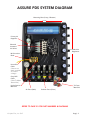
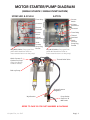
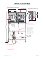
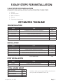
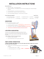
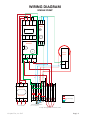
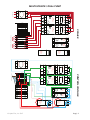
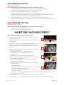
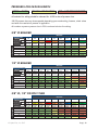
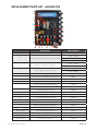
ZVC ASSURE PDS WITH
AQUA-LAB™
TECHNOLOGY
CHEMICAL DISPENSING SYSTEM
User Manual
REV C
4000029 revC1015
© Hydra-Flex,
Inc. 2015
© Hydra-Flex,
Inc. 2015
TABLE OF CONTENTS
Specifications
1
Recommended Maintenance 14
Assure PDS System Diagram 2
Air Operated Valve Replacement
14
Motor Starter / Pump Diagram
3
Layout Drawing
Trouble Shooting Pump Issues
Injector Issues Pressure Regulator Issues
Flow / Arch issues
Valve Issues
14
14
15
15
16
16
Injector Optimization Troubleshooting 16
Injector Vacuum Check
17
18
18
19
19
20
21
23
4
Estimated Installation Timeline
5
Installation Instructions
6
Wiring Diagram
Single Pump Multi-Source/Dual Pump 8
8
9
Start Up 10
Initial Injector Setup
11
Triple Foam Setup 11
Optimizing The System
12
Nozzle Setup
12
Chemical Usage Measurement
13
Appendix
Chem-Flex Injector Dilution Ratio Chart
Recommended Setup Starting Point
Chem-Flex Injector Part Numbers Pressure Loss In Run Length
Replacement Parts List Aqua-Lab Warranty
SPECIFICATIONS
POWER REQUIREMENTS
PUMPS
AIR-ACTUATED VALVES
20 GPM
24 VAC or 24 VDC or 120 VAC, 3.5 Watts Per Port
208-230V/3PH/8.9A or 460V/3PH/4.2A
DIMENSIONS (W x H)
FULL STAND
Width 47.5” x Height 78”
x Depth 28”
PUMP ASSEMBLIES
PANELS
MOTOR CONTROL UNIT
1-Pump
2-Pump
3-Pump
MD3
MD5
Single / Dual
24”x 48”
24” x 48”
36” x 48”
22” x 29”
22” x 29”
14” x 15”
WATER SUPPLY
Water Inlet Lines
Solution Outlet Lines
20 GPM
40 GPM
1” ID
1 1⁄2” ID or 2x 1” ID
Up to 3 GPM
3-5.5 GPM
6-8 GPM
1⁄2” OD Polyflow
1⁄2” ID Min.
5⁄8” ID Min.
Operating Water Pressure
200 PSI (Factory Set) Assuming 40 PSI City Feed
Maximum Water Source Temperature
140˚F
Water Filtration (Suggested)
50 Micron
AIR SUPPLY
Air Inlet Line
3/8” OD Polyflow Per MD Panel
Air Outlet Line
3/8” OD Polyflow Per Application
Air Inlet Pressure
60-120 PSI Dry Air
FOR ADDITIONAL SUPPORT CALL: 952-808-3640
OR VISIT US ON THE WEB: www.hydraflexinc.com
© Hydra-Flex, Inc. 2015
Page | 1
ASSURE PDS SYSTEM DIAGRAM
Mounting Slots (2 top, 2 Bottom)
16 3/8”
1
2
Primary Air
Regulator
3
1
Solenoid
Actuated
Air Valves
2
3
4
4
5
M12 Junction
Block
1
3
2
Home Run
Cable
(Goes to car
wash controller
for control
voltage)
5
Individual Air
Regulators
5A
4
5B
1
Grey M12
Cable
(Goes To Motor
Starter Box)
1
2
2
3
3
4
4
5
5A
5B
5C
5A
5C
5C
Hydra-Cannon
Manifold
Air Ports (Back)
Solution Ports (Front)
Tri-Foam
Manifold
REFER TO PAGE 21 FOR PART NUMBERS & DIAGRAMS
© Hydra-Flex, Inc. 2015
Page | 2
MOTOR STARTER/PUMP DIAGRAM
(SINGLE SOURCE / SINGLE PUMP SHOWN)
SPRECHER & SCHUH
EATON
Timer Relay
Current
Switch
Contactor
3 Phase
Disconnect
Thermal
Overload
Contactor
Timer Relay
Current
Switch
Thermal
Overload
3 Phase
Disconnect
Grey M12 Cables (Carry signal from
yellow M12 distribution block to
motor starter that turns on the pump)
Quick Connect 9’
Cordset For Pump
(Plugs Into Bottom
Of Motor Starter)
Quick
Connect
Pump Plug
Female
Quick
Connect
Pump Plug
Female
Grey M12 Cables (Carry signal from
yellow M12 distribution block to
motor starter that turns on the pump)
Thermal Relief Valve
Back-up Pump
Bypass Pressure
Regulator
Wye-Strainer
Pump Outlet
Feed Line To
MD Panels
REFER TO PAGE 22 FOR PART NUMBERS & DIAGRAMS
© Hydra-Flex, Inc. 2015
Page | 3
LAYOUT DRAWING
(2x) 3/8" Poly Flow Air Inlet Tubing
Provided By Others (100 PSI Max)
47.5”
5 Port Assure PDS
(1x) 230V / 480V Pump
Power Receptacle Included
21.9”
15.75”
78”
13”
(2x) 20' Signal Wire
To AQUA-LAB Included
30' Signal
Control Cable
Included
(1x) 6' Quick Change
Flexible Hose With
Regulator & Wye
Strainer To Assure
PDS With 1/2" Quick
Connect & Ball Valve
Included With Each
(1x) 6' X Ø1.0"
MNPT Quick
Change Pump
Inlet Hose
Included
(1x) Connection With
Valve To Accommodate
1" Male Npt Hose Must
Terminate Within 5
Feet Of Pump Inlet
(Ø1.0" Recommended)
Provided By Others
© Hydra-Flex, Inc. 2015
(1x) 12ft 230V / 480V
Pump Power Cord Included
With Each Pump
Page | 4
5 EASY STEPS FOR INSTALLATION
5 EASY STEPS FOR INSTALLATION
COMPLETE PRE-INSTALLATION CHECKLIST BEFORE THESE STEPS
1. Unpack
2. Set skid in place
3. Make connections
4. Start-up
5. Optimizing the equipment
ESTIMATED TIMELINE
PRE-INSTALLATION
WHO
TASK
EST. TIME
ZVC REP & CUSTOMER
DETERMINE LOCATION TO INSTALL EQUIPMENT
.25 HR
PLUMBER / ZVC REP
INSTALL WATER SUPPLY LINE
1 HR
ELECTRICIAN
INSTALL ELECTRICAL SUPPLY LINE
2 HR
TECHNICIAN / ZVC REP
LABEL ALL CONTROLLER RELAYS AT CONTROLLER
.5 HR
TECHNICIAN / ZVC REP
RUN SOLUTION AND AIR LINES (IF NECESSARY)
5 HR
TECHNICIAN / ZVC REP
INSTALL AIR SUPPLY LINE
1 HR
TOTAL LABOR HOURS
9.75 HRS
WHO
TASK
EST. TIME
ZVC REP / TECHNICIAN
SET SKID IN PLACE AND BOLT TO WALL
.5 HR
ZVC REP / TECHNICIAN
CONNECT WATER, AIR AND SOLUTION LINES
1 HR
TECHNICIAN
CONNECT CONTROL LEADS TO MAIN CONTROLLER OR JUNCTION BOX
2 HR
ZVC REP / TECHNICIAN
STARTUP (INJECTOR, METERING TIP AND NOZZLE SELECTION)
2 HR
ZVC REP / TECHNICIAN
DOCUMENT CONFIGURATION
.5 HR
TOTAL LABOR HOURS
6 HRS
WHO
TASK
EST. TIME
ZVC REP
MONITOR & RECORD PERFORMANCE
2 HR / WK
ZVC REP
MAINTENANCE PER SCHEDULE OR AS NEEDED
INSTALLATION
POST INSTALLATION
TOTAL HOURS SPENT
TOTAL CUSTOMER
TOTAL ZVC REP
.5 HR
13.75 HR
TOTAL ELECTRICIAN
4 HR
TOTAL PLUMBER
4 HR
© Hydra-Flex, Inc. 2015
Installation takes approximately ONE day. An electrician
and a plumber are needed for half a day.
Page | 5
INSTALLATION INSTRUCTIONS
General Skill Level
•
Mechanical: Basic - mounting equipment
•
Electrical: Advanced - three phase power and controls knowledge (local codes knowledge
required)
•
Plumbing: Moderate - principal supply line required
•
Pneumatic: Basic- pneumatic utility connection required
•
Chemical Knowledge: Moderate - chemical titrations required
Tools & Equipment Needed
• Drill with Phillips head
Useful Tools:
• Utility knife
• Concrete drill bit 5/32” • Wire stripper
• Adjustable wrench
• Socket set
• Amp Meter
• Screw driver set
• Teflon tape
• Volt Meter
UNPACKING
The AQUA-LAB PDS is shipped on a pallet.
1. Cut straps holding skid to pallet
2. Un-bolt the skid from the pallet.
3. Lift the skid from the pallet. Use assistance if necessary.
4. ***Be sure not to discard the manuals and accessories box.
LOCATION & MOUNTING
**If location was not identified during the Pre-Installation Process,
make sure to consider the proximity to feed water, power supply, and
the control cabinet as well as space near the system to store chemical
containers.
***See drawing in reference for general layout
1. Set skid in location identified
2. Optional: Bolt skid to wall using wall anchor plates
FEED WATER CONNECTION
**PRIOR TO CONNECTION, ENSURE THAT THE FEED LINES ARE FREE OF DEBRIS BY FLUSHING
OUT THE LINES FOR 15 MINUTES
•
Connect pre-run main water supply line to pump inlet with hose
supplied.
•
Single operating pump: 1” MNPT
•
Dual operating pump: 1-1/2” MNPT
© Hydra-Flex, Inc. 2015
Page | 6
PNEUMATIC CONNECTIONS
•
Connect pre-run 3/8” OD poly feed line to push connect fitting
on the side of the primary regulator.
•
Connect 3/8” OD poly lines from arch to each port
that will be foaming.
**If there are unused air ports,
back out the individual line
regulator until air no longer flows.
1. ELECTRICAL CONNECTIONS (HFI MOTOR STARTER)
a. Wire yellow homerun control cables to car wash control panel.
(See diagram below for wiring schematic)
• Manifold position below designates which port is associated to what color wire.
• Example: if you want Presoak 1 to be on manifold port 2, connect the green wire to your
controller relay for Presoak 1.
******************(HFI supplied motor starter)******************
Make sure all BLUE wires are separately capped with wire nuts so that they do not touch any other
electrical conductive objects (One Wire Per Nut!).
Ground - Green/yellow
(Left to right on water manifold, top to bottom
on air valves refer to diagram on page 2)
Neutral / Common - Red
2
1
5
5
Control Voltage Constant Hot / + Brown
3
1
Do Not Use - Blue (Cap With Wire Nut)
2
3
1
4
5
2
3
1
4
5
3
4
Hydra-Cannon Port 1 - White
Hydra-Cannon Port 2 - Green
Hydra-Cannon Port 3 - Yellow
5
2
3
1
4
2
3
1
5
3
4
6
4
Hydra-Cannon Port 5 - Pink
5
4
2
Hydra-Cannon Port 4 - Grey
2
1
To Motor Starter Box
b. Remove the cap from port 6 then, connect the grey M12 cables hanging out of the motor starter box
to the NEUTRAL/COMMON port 6 of the yellow M12 junction boxes.
i. If you have more panels than gray wires from the motor starter box, connect the lose gray
wires sent in the shipment into the same jumpers as the pre-wired gray cables. (This step
must be completed for unit to function.)
c. Connect Powerfast Cordset on motor(s) to motor starter box.
d. Connect male plug to outlet previously installed by electrician.
•
Make sure to follow all applicable electrical codes.
© Hydra-Flex, Inc. 2015
Page | 7
WIRING DIAGRAM
SINGLE PUMP
A1
L2
L3
A1
NO
T2
T3
NO
Thermal
Overload
97
T2
T3
Jumper
Disconect
2T1
4T2
PE
6T3/1
4T2/1
2T1/1
CB2/BLK
CB1/BLK
CB2/BLU
CB1/BLU
TEMP1
3 Phase
CB2/BRN
5L3
TEMP2
3L2
A2
98
CB1/BRN
1L1
18
Current
Switch
V+
T1
96
16
Valve Signal
95
15
Timer
Relay
Contacter
T1
B1
V-
L1
A2
Jumper
Jumper
Jumper
6T3
From Breaker
3 Phase
Control Voltage
From Grey M12 Cables
(Port 6 on M12 Block)
To Pump Through Power Fast Quick Connect
© Hydra-Flex, Inc. 2015
Page | 8
MULTI-SOURCE / DUAL PUMP
1L1
L1
A1
L2
L3
A2
NO
L1
A1
L2
A2
NO
CB3/BLK
A1
B1
15
A1
B1
15
Timer
Relay
L1
A1
L2
L3
A2
Contacter
T3
NO
NO
A1
T2
L3
T3
A2
Contacter
L2
NO
NO
16
B1
18
15
A2
Timer
Relay
A1
16
B1
18
15
A2
Timer
Relay
A1
CONTROL VOLTAGE
L1
T1
98
2T1/1
3 PHASE
L3
Timer
Relay
DC
Current
Switch
T2
97
6T3/2
Thermal
Overload
96
4T2/2
95
PE
T3
2T2/1
98
T2
Valve Signal
6T3/1
T1
CB3/BLK VJumper
4T2/1
T1
97
T3
CB3/BLU
Thermal
Overload
96
T2
CB2/BLU
Jumper
CB1/BLU
95
T1
5L3
Jumper
CB3/BRN
Contacter
A2
3L2
6T3
CB2/BRN
Contacter
18
6T3/2
NO
16
4T2/2
T3
PE
T2
A2
2T2/1
T1
18
6T3/1
NO
4T2/1
T3
16
DC
Current
Switch
1L1
3 Phase
4T2
Disconect
2T1
TEMP2
From Grey M12 Cables
TEMP1
98
CB1/BLK
T2
97
T3
CB2/BLK
Thermal
Overload
96
CB3/BLU
95
CB2/BLU
98
T2
CB1/BLU
T1
97
T1
CB3/BRN
Thermal
Overload
96
T3
CB2/BRN
95
T2
2T1/1
To Pump Through Power Fast Quick Connect
CB1/BLK V-
VCB2/BLK V-
T1
5L3
6T3
TEMP1
DC
Current
Sensor
DC
Current
Sensor
Page | 9
© Hydra-Flex, Inc. 2015
V+
CB1/BRN
3L2
3 Phase
4T2
Disconect
2T1
From Breaker
CB1/BRN
TEMP2
Valve Signal 2
START UP
!WARNING! PUMP MUST BE PRIMED BEFORE OPERATION
1. DISCONNECT & FLUSH
Close ball valve and remove the pump outlet line at the Hydra-Cannon
Manifold quick-connect (Image 1). Make sure water supply to pump
is turned on. Open ball valve and direct toward a drain or container to
remove the majority of the air from the pump until a steady stream of
water is flowing (approx. 1 min). Then close the ball valve.
2. CHECK ROTATION
Open ASSURE PDS Motor Starter Box (MSB) and ensure 3 phase
disconnect is on. (Note: Door will not open with disconnect on. Use a 1/4”
wrench or crescent wrench to turn it back on after opening door.) (MSB
with blue and black Eaton disconnect can be opened without shutting off
by depressing button under switch handle. Press small button with screw
driver to bypass disconnect (Image 2). !WARNING! - ELECTRIC SHOCK
HAZARD. HIGH VOLTAGE PRESENT INSIDE MOTOR STARTER BOX USE CAUTION!) Start the pump momentarily by depressing the center of
the contractor (image 3). !WARNING! RUNNING THE PUMP BACKWARD
WILL CAUSE CATASTROPHIC SYSTEM FAILURE! ENSURE THAT PUMP
ROTATION IS CORRECT (image 4) as indicated by the arrow on the casting
of the pump and that 200 psi can be reached.
•
If pump cannot regulate to 200 psi, remove pump motor cover
and look at shaft to confirm correct rotation.
•
Verify pump inlet pressure remains positive when running.
3. PURGE BYPASS
Start the pump and slowly open ball valve until it is wide open. Allow to
run for 60 seconds to flush lines and then close valve.
4. RECONNECT
Reconnect the pump outlet line to the Hydra-Cannon Manifold and open
ball valve.
5. DOUBLE CHECK
Confirm that the pump can obtain 200 psi while firing solenoids and that
the pump housing (stainless steel tube) is cool to the touch after a minute
in operation.
• If housing is hot or noisy, pump did not prime correctly.
• If pump does not prime, repeat steps 3-5.
• If not at 200 psi and the pump is correctly rotating you may need to
adjust the bypass regulator to obtain 200 psi (Image 5).
Verify pump prime 24 hours after operation to ensure prime held. Pay close
attention to the temperature of the pump shaft, the whole stainless steel
area (Image 6) should be the same temperature. If it starts getting hotter
than the supply water or greater than 140°, then it is likely that the pump did
not prime correctly which WILL CAUSE DAMAGE TO PUMPS. The motor
housing (painted portion) will be hot during operation.
© Hydra-Flex, Inc. 2015
Page | 10
INITIAL INJECTOR SETUP
(Based on field experience this is HFI’s recommended starting point)
1. Using the recommended starting point (Page 19) or the target flow rate and the chemical dilutions
chart (appendix Page 18) install the appropriate injector into each port.
2. Connect pre-run solution lines to each injector with the
supplied coupler and push connect fitting.
a. Be sure to use Teflon tape when connecting the
injector to the coupler and push connect fitting
to ensure there are no leaks.
b. Do not over tighten poly fittings or they may
crack.
3. Connect ¼” poly lines from each chemical container to the hose barb on the appropriate injector.
a. Ensure a foot valve or similar check valve/filter is installed on each line.
i. These must be present or metering tips may clog.
4. Metering tips will need to be installed to set dilution ratio (see appendix Page 18 for ratio charts to
determine tip.)
TRIPLE FOAM SETUP
(For ASSURE PDS if ordered with extra regulators)
If your MD5 panel was ordered with 3 air valves and 5 air regulators or with 5 air valves and 7 air
regulators the below instructions will show you how to setup your triple foam.
3 Valve / 5 Regulator ASSURE PDS
•
Your triple foam has been setup from the factory to be in port 3.
•
Insert your triple foam manifold into position 3 with your selected injectors already inserted.
•
On the side of the panel the 3rd, 4th, and 5th regulators (numbering starts at the top) will control
the air to each of your triple foam colors.
•
Insert your air lines to the arch into the bulkhead fittings on the bottom of the panel. The 3rd, 4th,
and 5th bulkhead (counting from left to right) will be the airlines for each color.
5 Valve / 7 Regulator ASSURE PDS
•
Your triple foam has been setup from the factory to be in port 5.
•
Insert your triple foam manifold into position 5 with your selected
injectors already inserted.
•
On the side of the panel the 5th, 6th, and 7th regulators (numbering
starts at the top) will control the air to each of your triple foam colors.
•
Insert your air lines to the arch into the bulkhead fittings on the bottom
of the panel. The 5th, 6th, and 7th bulkhead fittings (counting from left
to right) will be the airlines for each color.
Note: Occasionally if all three regulators are pre-set too high, you may
need to lower all three regulators to their lowest setting and then turn
them up to the desired pressure.
© Hydra-Flex, Inc. 2015
Page | 11
OPTIMIZING THE SYSTEM
CONSISTENTLY ACHIEVE THE DESIRED CLEANING AND PRESENTATION/
PERFORMANCE USING THE LEAST AMOUNT OF CHEMICAL AND WATER
INJECTORS VS. METERING TIPS VS. NOZZLES
THE KEY TO OPTIMIZING THE SYSTEM IS THROUGH TRIAL AND ERROR. DON’T BE
AFRAID TO TRY THESE STEPS TO ACHIEVE YOUR IDEAL PERFORMANCE
What do injectors do?
•
Increases or decreases the amount of water in the solution.
What do metering tips do?
•
Increases or decreases the amount of
chemical in the solution.
What do nozzles do?
•
Determines the pattern and back pressure
of the solution.
APPLICATION OPTIMIZATION
(REPEAT FOR EACH APPLICATION)
•
Application too wet
•
•
•
•
•
Too much chemical used
•
•
•
•
•
Decrease foaming air pressure
Decrease number of nozzle(s) and/or
size used on arch
Increase injector size (increases water)
Decrease metering tip
Decrease metering tip and injector
size (to maintain desired ratio)
No chemical
•
Decrease foaming air pressure
Increase injector size (increases water)
Decrease metering tip (decreases
chemical)
Nozzle sputters
•
•
•
•
Application too dry
•
•
•
•
Increase foaming air pressure
Reduce injector size (decreases water)
Increase metering tip (increases
chemical)
Nozzle fan pattern not filled
•
•
•
Check vacuum/backpressure of
injector for clogging (see page 17 for
Injector Vacuum Check Instructions or
pages 15 for troubleshooting)
Check foot valve
Check metering tip
Reduce nozzle size
Increase injector size (increases water)
Water not present at all nozzles on arch
•
•
•
•
•
Verify check valves are functioning
Verify nozzles are not plugged
Reduce number of nozzles
Reduce nozzle size
Increase injector size (increases water)
NOZZLE SETUP
(Optional For Maximized Optimization)
•
Using the recommended starting point (appendix) install the recommended nozzles.
• This may involve removing and plugging some ports.
• Due to the lower water usage determined by the injector of the ASSURE PDS you will need to
match the flow of the application device to the injector.
• Setup the nozzle spray patterns to “paint” the car - slightly overlapping each other.
© Hydra-Flex, Inc. 2015
Page | 12
MINIMUM NUMBER OF NOZZLES NECESSARY WITHOUT FOAMING AIR
(Assuming <10 PSI line loss and ~ 40 PSI at the nozzle)
INJECTOR FLOW RATE @ 200 PSI (GPM)
SPRAY NOZZLE SIZE
# 2.0
# 3.0
# 4.0
# 5.0
# 6.0
# 7.0
# 8.0
# 9.0
# 10.0
0.25
1
1
1
1
1
1
1
1
1
0.50
2
1
1
1
1
1
1
1
1
0.75
3
2
1
1
1
1
1
1
1
1.0
5
3
2
2
1
1
1
1
1
1.5
7
5
3
3
2
2
1
1
1
2.0
10
6
5
4
3
2
2
2
2
2.25
11
7
5
4
3
3
2
2
2
3.25
16
10
8
6
5
4
4
3
3
5.5
27
18
13
11
9
7
6
6
5
MINIMUM NUMBER OF NOZZLES NECESSARY WITH FOAMING AIR
(Assuming <10 PSI line loss and ~ 40 PSI at the nozzle)
SPRAY NOZZLE SIZE
# 2.0
# 3.0
# 4.0
# 5.0
# 6.0
# 7.0
# 8.0
# 9.0
# 10.0
4
2
2
1
1
1
1
1
1
0.50
8
5
4
3
2
2
2
1
1
0.75
13
8
6
5
4
3
3
2
2
1.0
17
11
8
7
5
5
4
3
3
1.5
26
17
13
10
8
7
6
5
5
INJECTOR FLOW RATE @ 200 PSI (GPM)
0.25
2.0
35
23
17
14
11
10
8
7
7
2.25
39
26
19
15
13
11
9
8
7
3.25
56
37
28
22
18
16
14
12
11
5.5
96
64
48
38
32
27
24
21
19
Elbows/Pipe Fittings
•
Elbows and other pipe fittings add back pressure by causing the fluid to change direction and
thus changing the fluid’s momentum. Try to find simpler ways to route your fluid without elbows.
Line Length
•
Longer lines add back pressure due to the inherent resistance caused by friction. See if you can
reduce the line length or increase the inside diameter.
CHEMICAL USAGE MEASURING
VERIFY TITRATION OF CHEMICALS BEFORE PROCEEDING
1. Set up lab scale with small bucket of chemical to be measured.
2. Put the suction line into the bucket.
3. Run the application being tested to “prime” the line. (All air bubbles must be
removed for accuracy.)
0
8
24
16
4. Record the Initial Weight from the scale. (Tarring the scale with weight on the scale can affect accuracy.)
5. Run the application for 1 vehicle (or manually for the same amount of time it would be on for 1
vehicle).
6. Record the Final Weight from the scale.
7. Subtract the Initial Weight from the Final Weight to determine the weight of used product.
8. Divide the Per Car Weight in grams by the specific gravity of the chemical to determine the milliliters
of chemical used per vehicle.
9. Repeat for each chemical application.
© Hydra-Flex, Inc. 2015
Page | 13
RECOMMENDED MAINTENANCE
THE RECOMMENDED SERVICE AND MAINTENANCE ON THE ASSURE PDS
SYSTEM ARE AS FOLLOWS.
Monthly
• Check/drain primary air regulator/filter separator.
• Check water filter and replace as needed (if installed).
• Check and clean wye strainer.
Semi-Annually
• Check and replace injector metering tips.
• Inspect and replace chemical lines as needed.
• Ensure lines are tightly secured to injector hose barbs, clip 1” off old hose as needed that was
stretched by hose barb.
Annually
• Clean water regulator.
• Inspect motor starter for corrosion, if identified order replacement/spare parts.
1-3 Years
• Inspect and replace injectors.
• Replace water valves.
• Replace main pressure regulator.
AIR OPERATED VALVE REPLACEMENT
1.
2.
3.
4.
5.
Shut off the ball valve to ASSURE PDS or Hydra-Cannon manifold.
Disconnect air line from front of valve.
Unscrew quick connect fitting by hand (DO NOT LOSE BLACK WASHER).
Unscrew valve assembly from the Hydra-Cannon manifold.
Screw new valve into manifold until hand tight and threaded pilot port is facing
forward.
6. Remove the cap from pilot port and thread in quick
Unscrew from
connect fitting to front of valve – HAND TIGHT ONLY.
manifold using this
7. Push air line back into fitting.
portion of valve
8. Open the ball valve to the Hydra-Cannon manifold.
TROUBLESHOOTING
PUMP ISSUES
PROBLEM
POTENTIAL CAUSES
SOLUTIONS
Pump Operates, But Only
Delivering 100-150 Psi
Incorrect motor rotation
Reverse rotation by interchanging two leads.
Pump not primed
See priming instructions.
Missing 1 of 3 phases
Wire according to diagram/check breaker (turn off on back).
Inadequate water supply
Check pressure on inlet side of pump to be sure
positive pressure is maintained.
Undersized piping
Replace with larger piping.
Leak on the inlet side
Make sure connections are tight.
Worn or defective pump parts
Replace worn parts or entire pump, clean parts if required.
Pump Operates, But Delivers
Little Or No Water
© Hydra-Flex, Inc. 2015
Page | 14
PROBLEM
Pump Will Not Start Or Run At
Full Speed
Excessive Noise From Pump
Pump Leaks
INJECTOR ISSUES
PROBLEM
Injector Is Not Drawing Chemical
- Passes Vacuum Pressure Check
No Flow From Injector
Injector Is Not Drawing Chemical
- Fails Vacuum Pressure Check
Injector stainless steel disintegrating
POTENTIAL CAUSES
SOLUTIONS
Constant hot not connected
Make sure constant control voltage is supplied in car
wash controller.
Blown fuse or circuit breaker
Could be due to blown pump motor. Try to turn breaker
back on or replace fuse. If breaker trips after trying to
fire motor it is most likely burned out. Replace with new
motor and pump.
Defective motor starter contactor
Replace motor starter contactor.
Thermal overload set too low/tripped
Adjust setting on thermal overload to match voltage.
Incorrect motor voltage
Voltage must be within 10% of motor rated voltage.
(Check that pump is wired for correct voltage.)
Defective motor
Replace motor.
3 phase disconnect turned off
Turn disconnect on.
Pump components damaged
Replace worn part or entire pump.
Current Sensor not seeing any
current
Turn on one valve and verify red light blinks fast, verify
at least 10 wraps of wire around current sensor.
Pump not secured firmly
Secure properly.
Restricted inlet
Clean or correct restriction.
Water regulator fluttering /
chattering
Try to adjust regulator down and then back up or
replace regulator/remove check valves/pressure
regulators from H20 feed to pump.
Cavitation (sounds like marbles in pump)
Increase inlet size/inlet pressure.
Worn mechanical seal
Replace pump.
Not primed
Re-prime pump.
Loose fittings, and or not enough
thread tape
Tighten fittings, and or take part off and put new
thread tape on.
Failed seals
Replace pump.
POTENTIAL CAUSES
SOLUTIONS
Clogged chemical feed
Check chemical hose, foot valve, metering tip, and
hose barb for debris or clogs.
Valve malfunction, valve not opening
Ensure minimum 60 psi on primary air regulator,
ensure valve receiving signal.
Clogged injector
Remove injector and blow out debris with compressed air.
No water supply
Check that the system has a supply of water.
Too much back pressure on injector
Clean or replace downstream check valves, increase
nozzle size or quantity, use larger tubing, or use
smaller flow injectors.
Clogged injector check valve
Blow compressed air through the chemical hose barb
on the injector to remove debris.
Clogged injector nozzle
Remove injector and blow out any debris with compressed air.
Defective injector
Replace injector.
Product specific - Sonny’s Rain Bar
Remove elbow at inlet to foam generator and remove nozzle.
Manifold inlet clogged (rare)
Remove end fittings and retention rod. Clean out inlet
holes to allow full flow.
Strong Hydro-Fluoric Acid
Call Hydra-Flex and order composite version of injectors.
PRESSURE REGULATOR ISSUES
PROBLEM
System Won’t Regulate Up To
200 Psi
© Hydra-Flex, Inc. 2015
POTENTIAL CAUSES
SOLUTIONS
Pump not primed
Follow priming instructions.
Debris in regulator
Remove regulator and clean out debris.
Motor rotation incorrect
Verify rotation / switch 2 leads.
Opening too many valves at once
System is limited by size of pump and size of injectors,
increase flow by adding secondary pumps or reduce
size / number of injectors open.
Defective check valve (if applicable)
Replace check valve.
Defective Regulator
Replace regulator.
Defective Pump
Replace Pump.
Page | 15
FLOW / ARCH ISSUES
PROBLEM
Flow At Arch Is Too Low
VALVE ISSUES
PROBLEM
POTENTIAL CAUSES
SOLUTIONS
Incorrect injector flow rate
selection
Replace with larger injector
System pressure too low
Ensure system pressure is set at 200psi
Foam generator plugged
Ensure cleaned and clear
Downstream plumbing restrictive
Increase size of plumbing / tubing, ensure check
valves are cleaned or new, reduce elbows in line or
other turns that would restrict
POTENTIAL CAUSES
SOLUTIONS
Valve Leaks Air Or Water Out
Top
Internal o-ring seal damaged /
worn
Valve Remains Open After Signal
Is Off
Manifold pressure is above 230 psi
Ensure primary air regulator reading at least 60 psi, turn
up to 80-90psi if possible and check again.
Remove valve from manifold, Carefully remove top of
valve (caution – under high spring pressure) push white
piston up with small allen wrench from opposite end and
check o-ring condition. Replace and lubricate if needed.
Remove valve from manifold, Carefully remove top of
valve (caution – under high spring pressure) push
white piston up with small screwdriver from opposite
end and check o-ring condition. Replace with 018 &
008 Viton O-ring and lubricate with Dow 111 valve lube.
Reduce pressure to manifold to 200 psi operating pressure.
Air exhaust muffler is clogged
Replace exhaust muffler.
Air pressure too low
Valve Will Not Open
Internal valve o-ring jammed /
twisted
INJECTOR OPTIMIZATION TOOL
BACKGROUND:
This tool is for initial setup and troubleshooting of Chem-Flex™ Injectors and an ASSURE PDS Chemical
Dispensing System. In order for the injector to work properly and draw chemical this gauge must be in the
“GREEN” section when installed immediately after an injector that is running. If the gauge is in the red you
will either see: intermittent chemical, no chemical draw, or chemical being applied at a very low pressure.
Back pressure refers to the pressure in the solution output line. Excessive back pressure is the main
reason that injectors will not draw. If there is ever any concern to why an injector is not drawing chemical,
the best and easiest way to diagnose the problem is to check the back pressure. See instructions below:
STEPS:
1. Plug the optimization tool into the
outlet line of injector and connect
solution output line.
2. Turn on function from car
wash controller to actuate
Hydra-Cannon valve such that
fluid is flowing through both the
injector and injector optimization
tool and out to the applicator.
Hydra-Cannon Valve
Injector
Injector Optimization Tool
Chemical Draw Line
3. Read injector optimization tool.
4. If the gauge is in the “RED
ZONE” the back pressure of the
outlet line is either too low or too
high. See steps below to correct.
© Hydra-Flex, Inc. 2015
Solution
Output Line
Chemical Bucket
Page | 16
BACK PRESSURE TOO HIGH
(UPPER RED SECTION):
(Back Pressure May Be Affected By One Or Several Of These Things)
1.
2.
3.
4.
5.
Foam generators are clogged/degraded. Clean or replace media in generator.
Injector flow size is too large. Go down an injector size (less GPM).
Nozzle size on the arch is too small. Go up in nozzle size.
Check valves are dirty and or failing. Clean or replace check valves.
There is a kink in the line or excess fittings (elbows and reducers increase the back pressure).
Check line and replace any kinked sections. Try to reduce fittings.
6. ID of tubing going out to the tunnel is too small. Go up a size in inside diameter.
7. Check valves have too high of cracking pressure. Replace check valve with lower pressure check valve.
8. Clean foot valve.
BACK PRESSURE TOO LOW
(LOWER RED SECTION):
(Back Pressure May Be Affected By One Or Several Of These Things)
1. Injector flow too low. Increase injector size.
2. Nozzle size too large. Reduce nozzle size.
INJECTOR VACUUM CHECK
(FOR TROUBLESHOOTING INJECTORS)
1. At the Chem-Flex injector, remove the chemical feed line from
the injector hose barb.
2. Attach the tubing of the vacuum gauge to the Chem-Flex hose
barb (Image A).
3. With the pump(s) on, manually activate the chemical that is to be
tested at the main car wash control cabinet. An injector that is
working properly will have a reading greater than or equal to (≥)
20 in Hg.
4. If vacuum reads <20 in/Hg (image B), remove solution metering
tip (image C) and retest. a. If retest vacuum reads >20 in/Hg (image D), The
solution metering tip is clogged. Replace the
metering tip.
b. If Retest vacuum reads <20 in/Hg, continue to STEP 5
5. Remove a nozzle on the arch or the chemical feed line from the
foam generator and retest vacuum.
a. If retest vacuum reads >20 in/Hg, back pressure is being
created. Continue to STEP 6.
b. If back pressure is not still not being created try these steps
and retest after each:
A
B
C
1. Clean nozzle tips.
2. Loosely replace media in foam generator. Do not over pack.
D
3. Decrease air pressure for foaming.
4. Try smaller injector (this will produce less flow and thus
less back pressure).
c. If retest vacuum reads <20 in/Hg, replace injector and retest. If vacuum continues to read <20 in/
Hg, call your service provider.
6. Repeat steps 2-5 for each chemical lane that a vacuum reading is needed for.
7. Once testing is complete, turn off the ASSURE PDS pump from the main car wash control cabinet.
© Hydra-Flex, Inc. 2015
Page | 17
APPENDIX
CHEM-FLEX INJECTORS - CHEMICAL DILUTION RATIOS
(Assumes feed pressure of 200 PSI)
NOTE: Dilution ratios given above are based on drawing water through the metering tips and
are meant as a starting point for system configuration. Results are expected to vary when drawing
chemicals due to differences in viscosity and temperature.
#8-32 METERING TIPS
Metering Tip
Flow Rate
(GPM) at 200
PSI
0.25
0.50
0.75
1.00
1.50
2.00
2.25
3.25
5.50
Injector
Color
White
Yellow
Tan
Red
Orange
Gray
Blue
Light
Green
Dark
Green
Nozzle
Size
0.029”
(0.7 mm)
0.040”
(1.0 mm)
0.051”
(1.3 mm)
0.057”
(1.4 mm)
0.070”
(1.8 mm)
0.083”
(2.1 mm)
0.086”
(2.2 mm)
0.098”
(2.5 mm)
0.125”
(3.2 mm)
COPPER
1: 57
1: 104
1: 155
1: 195
1: 281
1: 406
1: 468
1: 629
1: 1074
PUMPKIN
1: 43
1: 82
1: 119
1: 126
1: 238
1: 348
1: 398
1: 554
1: 946
BURGUNDY
1: 34
1: 67
1: 97
1: 111
1: 207
1: 304
1: 347
1: 495
1: 845
LIME
1: 28
1: 57
1: 81
1: 100
1: 183
1: 270
1: 307
1: 447
1: 764
TAN
1: 28
1: 57
1: 81
1: 100
1: 183
1: 270
1: 307
1: 447
1: 764
ORANGE
1: 23
1: 44
1: 64
1: 78
1: 137
1: 196
1: 215
1: 314
1: 536
TURQUOISE
1: 17
1: 31
1: 45
1: 55
1: 91
1: 126
1: 134
1: 197
1: 336
PINK
1: 14
1: 24
1: 35
1: 42
1: 68
1: 93
1: 98
1: 143
1: 224
LIGHT BLUE
1: 11
1: 17
1: 24
1: 31
1: 47
1: 64
1: 66
1: 98
1: 166
BROWN
1: 10
1: 15
1: 22
1: 28
1: 43
1: 58
1: 59
1: 88
1: 150
RED
1: 12
1: 17
1: 23
1: 34
1: 45
1: 46
1: 69
1: 116
WHITE
1: 12
1: 16
1: 22
1: 31
1: 42
1: 43
1: 64
1: 108
GREEN
1: 11
1: 14
1: 20
1: 28
1: 37
1: 38
1: 55
1: 94
BLUE
1: 10
1: 12
1: 17
1: 23
1: 30
1: 31
1: 46
1: 77
1: 9
1: 12
1: 16
1: 20
1: 22
1: 31
1: 52
BLACK
1: 10
1: 13
1: 16
1: 17
1: 24
1: 40
PURPLE
1: 6.6
1: 8.3
1: 9
1: 10
1: 13
1: 21
GRAY
1: 5.3
1: 6.7
1: 6.9
1: 7.6
1: 10
1: 16
OPEN
1: 4.9
1: 5.3
1: 5.2
1: 6.0
1: 6.1
1: 10
YELLOW
There may be slight variations of performance in injectors and metering tips that are unavoidable due to manufacture tolerances.
Using the same tip color from site to site is a good starting point. However with the potential for variation from part to part it is
reasonable to still need to do some adjustments from there.
SPIRAL METERING PLUGS
Spiral Plug Length
Flow Rate
(GPM) at
200 PSI
0.25
0.50
0.75
1.00
1.50
2.00
2.25
3.25
5.50
Injector
Color
White
Yellow
Tan
Red
Orange
Gray
Blue
Light
Green
Dark
Green
Nozzle
Size
0.029”
(0.7 mm)
0.040”
(1.0 mm)
0.051”
(1.3 mm)
0.057”
(1.4 mm)
0.070”
(1.8 mm)
0.083”
(2.1 mm)
0.086”
(2.2 mm)
0.098”
(2.5 mm)
0.125”
(3.2 mm)
3.00”
1: 251
1: 503
1: 754
1: 1006
1: 1509
1: 2012
1: 2263
1: 3269
1: 5532
2.00”
1: 181
1: 363
1: 544
1: 726
1: 1089
1: 1451
1: 1633
1: 2359
1: 3991
1.00“
1: 104
1: 208
1: 311
1: 415
1: 623
1: 831
1: 934
1: 1350
1: 2284
0.75”
1: 82
1: 165
1: 247
1: 329
1: 494
1: 659
1: 741
1: 1071
1: 1812
0.50”
1: 59
1: 119
1: 178
1: 238
1: 357
1: 475
1: 535
1: 772
1: 1307
0.25”
1: 34
1: 68
1: 102
1: 136
1: 204
1: 272
1: 306
1: 442
1: 748
***Remove all standard metering tips when using a Metering Plug in an application. 3/8” Polyflow (LLDPE) tubing is required to
ensure a seal between the tube wall and the flats on the OD of the Meter Plug.
© Hydra-Flex, Inc. 2015
Page | 18
RECOMMENDED SETUP STARTING POINTS
APPLICATOR
INJECTORS PART NUMBER/COLOR
Scent Dispenser
618057 (1 GPM)
CTA Nozzles (For Showerhead, See Below)
618057 (1 GPM)
Foam Stick
618070 (1.5 GPM)
Mitter/Warp Nozzles
618070 (1.5 GPM)
Undercarriage/Rust Inhibitor
618083 (2.0 GPM)
V Jet Or Flat Fan Nozzle Arch
618086 (2.25 GPM)
K12 Nozzle Arch
618086 (2.25 GPM)
K15 Nozzle Arch
618098 (3.25 GPM)
Hockey Puck
1 Row Of Holes
618051 (.75 GPM)
2 Rows Of Holes
618057 (1 GPM)
3 Rows Of Holes
618070 (1.5 GPM)
Showerhead
1 Row Of Holes
618057 (1 GPM)
2 Rows Of Holes
618070 (1.5 GPM)
3 Rows Of Holes
618083 (2.0 GPM)
1 Row Of Holes
618086 (2.25 GPM)
2 Rows Of Holes
618098 (3.25 GPM)
3 Rows Of Holes
618125 (5.5 GPM)
Duo-Foam w/
(2X) 618098 (3.25 GPM)
Triple-Foam w/
(3X) 618086 (2.25 GPM)
Quad-Foam w/
(4X) 618086 (2.25 GPM)
Rain Bar
Foam Curtain - Choose Foam Accessory
Based On # Of Inputs/Foam Generators**
High Flow Device w/ 618086 (2.25 GPM)
High Flow Foam Curtain Application (10+ GPM)
Foaming Air: Start at 25 PSI (adjust based on unique application)
CHEM-FLEX INJECTOR PART NUMBERS
QUICK CONNECT INJECTORS - PC2 X 3/8” NPT CONNECTIONS
(For exclusive use with Aqua-Lab™ Chemical Dispensing Systems)
COLOR
FLOW
ORIFICE
FLOW RATE @
200 PSI
SINGLE BARB
DUAL BARB
TRIPLE BARB
WHITE
0.029
.25 GPM
618029
-
YELLOW
0.040
.5 GPM
618040
629040
-
TAN
0.051
.75 GPM
618051
629051
639051
RED
0.057
1.0 GPM
618057
629057
639057
ORANGE
0.070
1.5 GPM
618070
629070
639070
GRAY
0.083
2.0 GPM
618083
629083
639083
-
BLUE
0.086
2.25 GPM
618086
629086
639086
LIGHT GREEN
0.098
3.25 GPM
618098
629098
639098
DARK GREEN
0.125
5.5 GPM
618125
629125
639125
SPECIFICATIONS
Pressure Range:
Temperature Range:
Maximum Wrench Torque:
Up to 500 PSI Max. (34 bar) Inlet, 333 PSI (23 bar) Max. Outlet
33°F - 175°F ( .5°C - 79°C)
30 ft-lbs (41 N-m)
© Hydra-Flex, Inc. 2015
Page | 19
PRESSURE LOSS IN RUN LENGTH
GREEN = GOOD
YELLOW= USE CAUTION
RED = NOT RECOMMENDED
All solution line tubing should be selected for 10 PSI or less of pressure loss.
*20 PSI pressure loss may be acceptable depending upon nozzle sizing, foamers, check valves
and other line restrictions present in application.
All numbers represent pressure loss in PSI for selected solution line tubing.
5/8” ID BRAIDED
Flow Rate (GPM)
at 200 PSI
Injector Color
Nozzle Size
Run Length
150’
125’
100’
75’
50’
25’
0.25
White
INJECTOR
0.50
Yellow
0.75
Tan
1.00
1.50
Red
Orange
Injector Color
Nozzle Size
Run Length
150’
125’
100’
75’
50’
25’
Injector Color
Nozzle Size
Run Length
150’
125’
100’
75’
50’
25’
© Hydra-Flex, Inc. 2015
3.25
5.50
Blue
Light Green
Dark Green
4 PSI
7 PSI
18 PSI*
0.040”
(1.0 mm)
0.051”
(1.3 mm)
0.057”
(1.4 mm)
0.070”
(1.8 mm)
0.083”
(2.1 mm)
0.086”
(2.2 mm)
1 PSI
1 PSI
1 PSI
1 PSI
2 PSI
3 PSI
4 PSI
1 PSI
1 PSI
1 PSI
1 PSI
1 PSI
1 PSI
1 PSI
1 PSI
1 PSI
1 PSI
1 PSI
1 PSI
1 PSI
1 PSI
1 PSI
1 PSI
1 PSI
1 PSI
1 PSI
1 PSI
2 PSI
2 PSI
0.25
White
3 PSI
2 PSI
1 PSI
2 PSI
1 PSI
1 PSI
1 PSI
1 PSI
3 PSI
3 PSI
2 PSI
1 PSI
0.098”
(2.5 mm)
6 PSI
5 PSI
4 PSI
3 PSI
2 PSI
0.50
Yellow
0.75
Tan
1.00
1.50
Red
Orange
2.00
Gray
Dark Green
21 PSI
56 PSI
0.083”
(2.1 mm)
0.086”
(2.2 mm)
1 PSI
1 PSI
2 PSI
3 PSI
5 PSI
8 PSI
9 PSI
18 PSI*
6 PSI
11 PSI*
0.25
White
1 PSI
1 PSI
1 PSI
1 PSI
1 PSI
2 PSI
2 PSI
1 PSI
1 PSI
1 PSI
3 PSI
2 PSI
2 PSI
1 PSI
1 PSI
6 PSI
4 PSI
0.50
Yellow
0.75
Tan
9 PSI
7 PSI
3 PSI
5 PSI
2 PSI
4 PSI
1 PSI
2 PSI
11 PSI*
8 PSI
4 PSI
1.00
1.50
Red
Orange
2.00
5.50
Gray
Blue
Light Green
Dark Green
44 PSI
88 PSI
239 PSI
0.083”
(2.1 mm)
0.086”
(2.2 mm)
1 PSI
4 PSI
6 PSI
9 PSI
18 PSI*
30 PSI
37 PSI
6 PSI
12 PSI*
18 PSI*
3 PSI
6 PSI
1 PSI
1 PSI
1 PSI
2 PSI
1 PSI
1 PSI
5 PSI
4 PSI
3 PSI
1 PSI
26 PSI
3.25
0.070”
(1.8 mm)
3 PSI
36 PSI
4 PSI
9 PSI
INJECTOR
0.057”
(1.4 mm)
1 PSI
47 PSI
2.25
2 PSI
0.051”
(1.3 mm)
7 PSI
14 PSI*
0.125”
(3.2 mm)
18 PSI*
0.040”
(1.0 mm)
5 PSI
0.098”
(2.5 mm)
8 PSI
0.029”
(0.7 mm)
1 PSI
4 PSI
Light Green
0.070”
(1.8 mm)
1 PSI
6 PSI
Blue
0.057”
(1.4 mm)
1 PSI
9 PSI
5.50
0.051”
(1.3 mm)
1 PSI
13 PSI*
3.25
0.040”
(1.0 mm)
1 PSI
16 PSI*
2.25
0.029”
(0.7 mm)
1 PSI
0.125”
(3.2 mm)
INJECTOR
3/8” ID, 1/2” OD POLY TUBE
Flow Rate (GPM)
at 200 PSI
Gray
2.25
0.029”
(0.7 mm)
1/2” ID BRAIDED
Flow Rate (GPM)
at 200 PSI
2.00
11 PSI*
7 PSI
4 PSI
2 PSI
22 PSI
14 PSI*
8 PSI
36 PSI
23 PSI
12 PSI*
28 PSI
22 PSI
15 PSI*
7 PSI
0.098”
(2.5 mm)
73 PSI
54 PSI
42 PSI
28 PSI
13 PSI*
0.125”
(3.2 mm)
200 PSI
142 PSI
106 PSI
73 PSI
34 PSI
Page | 20
REPLACEMENT PARTS LIST - ASSURE PDS
Q
B
C
A
D
L
E
H
F
K
O
J
M
G
P
N
I
PART NAME
A
MD Primary Air Regulator
PART NUMBER
1001184
24 VAC - 1001428
B
Solenoid Actuated Air Valve Replacement - Foaming
24 VDC - 1001429
120 VAC - 1001430
120 VAC - 3000948
C
M12 X Din I Air Regulator - With LED
D
Primary Air Regulator Replacement Bowl
E
M12 Junction Block - 6 Port, With 30’ Homerun Cable
3000412
F
Outlet Pressure Gauge 0-400 PSI Bottom Mount
3000491
G
Air Actuated Hydra-Cannon Valve Replacement Kit
Stainless Steel - 3000925
H
1/4” Poly Tubing
3000812
Duo-Foam Manifold Kit (NOT SHOWN)
1001289
I
24 VDC or 24 VAC - 3000958
Aluminum - 3000952
Plastic - 3000870
Tri-Foam Manifold Kit
1001288
J
Small Regulator & 0-60 PSI Gauge
3000808
K
10-32” X 1/4” Push-To-Connect Air Fitting For Air Valve
3000987
L
1/4” Push To Connect Tee
3000815
M
1/2” NPT Male Quick Connect - Brass
3000500
N
Single Black Hydra-Cannon Replacement Assembly
1001384
O
Hydra-Cannon End Fitting Assembly
1001556
P
Hydra-Cannon Interface Fitting Assembly
1001557
Q
3/8” Poly Tubing
3000520
(NOT SHOWN)
Solenoid O-Ring Replacement Kit
1001155
(NOT SHOWN)
1/4” Hose Barb Foaming Air Check Valve
3000819
(NOT SHOWN)
1/4” Push To Connect To 1/8” NPT Elbow
3000803
(NOT SHOWN)
Anti-Siphon Kit (Contains 5)
1001436
© Hydra-Flex, Inc. 2015
Page | 21
REPLACEMENT PARTS LIST
ASSURE PDS PUMP
ASSURE PDS SINGLE
SOURCE MOTOR STARTER
E
F
K
I
A
D
H
B
C
J
G
PART NAME
PART NUMBER
A
Replacement/Backup 20 GPM Pump
1001362
B
1” Male Quick Connect - Brass
3000205
C
1” Wye Strainer, 20 Mesh
3000490
D
1” Female Quick Connect - Brass
3000206
E
Thermal Relief Valve, 1/2” NPT
3000323
F
Quick Connect 9’ Cordset For Pump
3000782
G
40 GPM Bypass Pressure Regulator - Stainless Steel
3000464
(NOT SHOWN)
1” NPT T16 Wye Strainer Screen & Gasket Kit
1001938
(NOT SHOWN)
1” NPT T15 Wye Strainer Screen & Gasket Kit
1001939
(NOT SHOWN)
20 GPM Quick Connect Regulator Plumbing Assembly
1001775
(NOT SHOWN)
1/2” Female Quick Connect - Brass
3000502
(NOT SHOWN)
1/2” Ball Valve - Brass
3000565
(NOT SHOWN)
Manifold Inlet Hose 1/2” ID Hose - 1/2” NPT Ends - 72”L
3000579
(NOT SHOWN)
20 GPM Quick Connect Regulator Pluming Assembly
1001775
PART NAME
PART NUMBER
Thermal Overload - Sprecher & Schuh
3000862
H
24 VAC - 3000863
I
Contactor - Sprecher & Schuh
24 VDC - 3000864
120 VAC - 3000865
J
Current Sensor
K
Time Relay
© Hydra-Flex, Inc. 2015
AC - 3000666
DC - 3000866
3000664
Page | 22
ASSURE PDS WARRANTY
FACTORY LIMITED
Hydra-Flex, Inc warrants its equipment to be free from defect in material or workmanship under proper
normal use for a period of one (1) year beginning the date of purchase.
Hydra-Flex, Inc’s liability shall be limited to repair or replacement of parts found to be defective within the
warranty period and following Hydra-Flex, Inc’s inspection. Hydra-Flex, Inc shall have the option requiring
the return of defective material to establish the purchaser’s claim. In the event of repair or replacement
this limited warranty is non-cumulative. Neither labor nor transportation charges are included in this
warranty.
This warranty is based upon the proper care and maintenance of the warranted equipment. Warranty
does not apply if the merchandise is altered or modified in any way. Warranty does not apply to any
equipment which has been subject to misuse, inappropriate use of tools, including exposure to harsh
chemicals, neglect, lack of maintenance, freezing, fluid hammer, accident, third party damage, fluid
impurities such as sand or minerals, acts of God or acts of war. Nor does it apply to any equipment which
has been repaired or altered by anyone not so authorized by Hydra-Flex, Inc. All equipment must be
properly installed in accordance with specified plumbing, electrical, and mechanical requirements. The
warranty does not apply to normal wear and tear or routine maintenance components as described in the
equipment manual.
Except as expressly stated herein, Hydra-Flex, Inc shall not be liable for damages of any kind in
connection with the purchase, maintenance, or use of this equipment including loss of profits and all
claims for consequential damages. This limited warranty is in lieu of all other warranties expressed or
implied. Hydra-Flex, Inc neither assumes nor authorizes any person to assume for it any other obligation
or liability in connection herewith. This warranty is neither assignable nor transferable.
Transportation damage claims are to be submitted to the carrier of the damaged material.
680 East Travelers Trail • Burnsville, MN 55337
T: 952-808-3640 • F: 952-808-3650 • www.hydraflexinc.com • [email protected]
© Hydra-Flex, Inc. 2015
4000022 revC1015
Page | 23