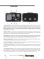
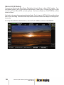
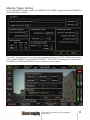
1
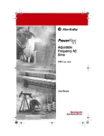
Stereoscopic 3D Camera
Sync/Power Distribution for
the Silicon Imaging 2K Mini
User Manual
Thank you for purchasing this Product.
Before operating this unit, please read the Instructions
carefully to ensure best possible performance.
Silicon Imaging
2
Stereoscopic 3D Camera Sync/Power Distribution
User Manual
Disclaimer
Silicon Imaging has attempted to provide clear and accurate information in
this User Guide. The information in this document is provided strictly on an
“as is” basis and Silicon Imaging will not be held responsible for issues arising from typographical errors or user’s interpretation of the content. Users
should refer to local and professional guidance on issues of safety. Silicon
Imaging reserves the right to revise this User Guide and make changes from
time to time in the content thereof without obligation to notify any person of
such revisions or changes. In no event shall Silicon Imaging, its employees or
authorized agents be liable to you for any damages or losses, direct or indirect, arising from the use of any technical or operational information contained
in this document.
Stereoscopic 3D Camera Sync/Power Distribution
User Manual
3
Important Safety Instructions
Read all of these instructions carefully.
Keep these instructions.
Heed all warnings.
Follow all instructions.
Do not use this apparatus near water.
Clean only with dry cloth.
Do not block any ventilation openings. Install in accordance with the manufacturer’s instructions.
Do not install near any heat sources as radiators, heat registers, stoves, or
other apparatus (including amplifiers) that produce heat.
Protect the power cord from being walked on or pinched particularly at plug,
convenience receptacles, and the point where they exit from the apparatus.
Only use attachments/accessories specified by the manufacturer.
Unplug this apparatus during lightning storms or when unused for long periods of time.
Refer all servicing to qualified service personnel. Servicing is required when
the apparatus has been damaged in any way, such as power-supply cord or
plug is damaged, liquid has been spilled or objects have fallen into the apparatus, the apparatus has been exposed to rain or moisture, does not operate
normally, or has been dropped.
Do not leave in direct sunlight
Only use unit in advised temperature range from 0° to +50° Celsius (32° to 122° Fahrenheit)
4
Stereoscopic 3D Camera Sync/Power Distribution
User Manual
CAUTION
RISK OF ELECTRONIC SHOCK
DO NOT OPEN
CAUTION
TO REDUCE THE RISK OF ELECTRIC SHOCK,
DO NOT REMOVE COVER (OR BACK).
NO USER SERVICEABLE PARTS INSIDE.
REFER SERVICING TO QUALIFIED SERVICE
PERSONNEL.
The lightning flash with arrowhead
symbol, within an equilateral triangle,
is intended to alert the user to the
presence of non-isolated "dangerous
voltage" within the products enclosure
that may be of sufficient magnitude to
constitute a risk of electric shock to
persons.
The exclamation point within an equilateral triangle is intended to alert the
user to the presence of important
operating and maintenance (service)
instructions in the literature accompanying the appliance.
WARNING
TO REDUCE THE RISK OF FIRE OR SHOCK
HAZARD, DO NOT EXPOSE THIS EQUIPMENT
TO RAIN OR MOISTURE:
CAUTION
TO REDUCE THE RISK OF FIRE OR SHOCK
HAZARD AND ANNOYING INTERFERENCE, USE
THE RECOMMENDED ACCESSORIES ONLY.
CAUTION
TO REDUCE THE RISK OF FIRE OR SHOCK
HAZARD, REFER CHANGE OF SWITCH SETTING INSIDE THE UNIT TO QUALIFIED SERVICE
PERSONNEL.
Stereoscopic 3D Camera Sync/Power Distribution
User Manual
5
6
Stereoscopic 3D Camera Sync/Power Distribution
User Manual
SiliconDVR – Stereo 3D Operation
Introduction
Two Silicon Imaging SI-2K cameras can be used to shoot Stereo-3D content when
the units are synchronized to capture at the same frame rate and starting their scanning from top to bottom at the same time. Each SI-2K Recorder or PC/Laptop with
SiliconDVR records one of the two camera views (ie. left or right eye imagery).
In order to synchronize the scanning, a connection is made between two cameras, which the
Sync/Power Distribution Unit provides power and synchronizes exposure timing between
two Silicon Imaging 2K Mini cameras for capturing stereo 3D. It provides a single SI-2K compatible “remote start” port insuring simultaneous start of two recorders. The unit monitors and
displays camera synchronization status, continuously verifying that both are operating and
synchronizing at the same frame rate.
The cameras can be powered and synchronized to each other using the Sync/Power
Distribution Unit. Each Si-2K Mini has two LEMO connections an 8-pin (PWR/CTRL) and
12-pin (NETWORK). The 12-pin LEMO is used for the Gigabit Ethernet data transmission and optional Power. The 8-pin LEMO is used for Power, Record Control and MasterSlave stereo synchronization.
Stereoscopic 3D Camera Sync/Power Distribution
User Manual
7
Connections
1. Power Input Port: This accepts DC power via an industry-standard 4-pin “XLR” connector. The voltage must be no greater than 19 volts to insure that the cameras are not damaged. Do not connect 24
volt cinema batteries to this device! The unit provides additional regulated 12 volt power outputs compatible with SI-2K accessories. In order for these auxiliary outputs to operate properly, the input voltage
must be higher than 13.0 volts. The unit will continue to operate at voltages below 10 volts, however
the supplied cameras may not.
2. Master Camera: This is used to connect to the camera which will provide the “master” timing in the
stereo setup. The camera should be connected to the unit using a “straight-through” cable. When using
separate recorders, configure this camera in SiliconDVR as the “Master”.
3. Slave Camera: This is used to connect to the camera which will be receiving and external synchronization signal in the stereo setup. The camera should be connected to the unit using a “straight-through”
cable. When using separate recorders, configure this camera in SiliconDVR as the “Slave”.
4. Master Camera Status: This LED is used to indicate the operating condition of the master camera.
The meaning of the indications is described later in this manual.
5. Slave Camera Status: This LED is used to indicate the operating condition of the slave camera. The
meaning of the indications is described later in this manual.
6. Remote start button port: This is used to connect an external pushbutton to control the start and
stop of the recording. Additionally, this port provides unregulated power which may be used to operate
accessories.
7. Auxiliary power outputs: These connections provide three different voltages to operate accessories. A regulated 5 volt, regulated 12 volt and unregulated pass-through of the input voltage are available on each of these connectors. To insure safety and proper operation of the unit and cameras, power
consumption limits must be observed. These limits are provided in Specifications (page 18).
8
Stereoscopic 3D Camera Sync/Power Distribution
User Manual
Setup
To help insure proper function, perform each of the following steps precisely as described and
in the order indicated.
1.Connect both cameras to the master and slave ports using two straight-through LEMO 8-pin
cables, Silicon Imaging part number 26157 (18”) or equivalent.
2.Insure that both cameras are connected via their LEMO 12-pin data ports to the recorders.
Both cable types can be used, either the “data only” cables (P/N 23057 for a 5 m, P/N 22710 for a
10 m, P/N 23058 for a 25 m), or the P+S Technik “data and power” cables (P/N 23059 for a 5 m, P/N
23060 for a 10 m, P/N 23136 for a 25 m) The “data only” cables are RJ45 to LEMO 12-pin cables,
which plug in the rear panel of the SI-2K, and the “data and power” cables are connected in front,
as illustrated above.
3.Connect an external remote start pushbutton. You must use a Silicon Imaging approved accessory such as the Start/Stop Handgrip (P/N: 21423), or see page 20 on compatibility.
4.Apply power via the power input.
5.Observe the initialization sequence for the unit. Shortly after connecting power, the master
and slave status indicators will cycle colors alternately for approximately two seconds.
6.At this point, the camera status indicators will typically be red. This is an indication that the
cameras have not been configured to operate yet.
7.(for dual recorder configurations) Launch SiliconDVR for the camera connected as
“Master”. Configure the camera as master, then launch SiliconDVR for the camera connected
as “Slave”. It’s important that the master camera be operating prior to the slave camera.
8.Check the status indicators. As each camera begins to operate, the color will change from red
to green. The system is synchronized and ready when both indicators are continuously green.
Don’t forget to SET BLACK carefully in SiliconDVR, before start of recoding.
Stereoscopic 3D Camera Sync/Power Distribution
User Manual
9
Silicon DVR Setup
Connect two Minis to the Sync/Power Distribution Unit with 8-pin to 8-pin LEMO cables. Connect battery power (XLR-4) and Record Input button (Fisher 3-pin). Connect your Mini to your
recorder and start SiliconDVR on both systems. Set one as Master (in CAM PREFS) and the
other as Slave.
Set both to the same frame rate and shutter Mode. Don’t forget to SET BLACK carefully before
start of any recording. Press the Start-Stop button and both cameras will begin recording simultaneously.
To setup SiliconDVR for Master-Slave, select UTILITY MENU and then CAM PREFS:
10
Stereoscopic 3D Camera Sync/Power Distribution
User Manual
Master / Slave Setting
In the CAM PREFS screen, under 3D CAMERA SYNC MODE change the default DISABLE to
either MASTER or SLAVE.
Press OK. The system will reconnect to the camera and return to UTILITY MENU with live Preview. OPEN PROJECT or start a NEW PROJECT. EXIT UTILITY and return to main screen.
Set RESOLUTION/FRAME RATE on both systems to same values.
Stereoscopic 3D Camera Sync/Power Distribution
User Manual
11
Black Setting
During the initial use of a camera, the software will detect a lack of a black reference image and
automatically requests the capture of a reference frame.
To perform this, completely cover the lens and click on OK. The software will gather a black
level is set for every pixel and also form a deviant pixel map which is used to automatically correct the image data.
Black setting should be performed on a regular basis, especially when the temperature of the
2K MINI camera head changes since this will cause changes in the black level of individual
pixels.
12
Stereoscopic 3D Camera Sync/Power Distribution
User Manual
Supported Resolutions and Frame Rates
Modes:
Frame Rates:
full 2K (2048x1152)
2048x1080
1920x1080
2048x856
1280x720
960x540
23.976
24
25
29.97
30
40
48
50
59.94
60
72
85
150
Unit provides precise frame synchronization during
record and also insures that under normal operating
conditions, the first frame of each clip coincides.
Unit provides precise frame synchronization at these
frame rates. Due to the high frame rates, recorders
may not always start on the same frame, although the
cameras are synchronized. In post-production, the first
frames of one clip may need to be removed to coincide
start frames. I’t s advisable to use a clapperboard or
timecode device to establish a time reference point.
Stereoscopic 3D Camera Sync/Power Distribution
User Manual
13
14
Stereoscopic 3D Camera Sync/Power Distribution
User Manual
Operation
The only control used during operation is the external remote start pushbutton. Prior to
starting the record, insure that both the master and slave indicators are showing steady
green. Depress the pushbutton for approximately one second to begin the recording
and release the button. When the pushbutton is depressed the Master camera status
indicator will blink blue then return to a stable green. The “tally” lights on the back of both
cameras should illuminate as the recorders start. Both camera status indicators should
remain steadily green during the recording. To end the recording, depress the pushbutton again for approximately one second and observe that the tally lights go off. The
Master camera status indicator will blink blue again when the pushbutton is depressed to
end recording then return to a stable green light.
Camera Status Indicators
Green-green light: Both cameras operating and in sync
Green-red light: Slave camera not operating or disconnected
Red and Red-blue blinking: Master camera not operating or disconnected
Red-red light: Neither camera operating or both disconnected
Short blue-blink and green light: Record button pushed
Green and Red-blue blinking: Phase error - check Master/Slave configuration
Stereoscopic 3D Camera Sync/Power Distribution
User Manual
15
Troubleshooting
Interpreting the Camera Status Indicators
A red light indicates that there is no synchronization pulse being emitted by
the respective camera.
A green light on the master indicates that it is generating a synchronization
signal.
A green light on the slave indicates that it is receiving the synchronization
signal from the master and both cameras are running at the same frame
rate.
Alternating red/blue on the slave indicates that there is a frame rate or
synchronization mis-match between cameras. Check that the master and
slave settings are correct and that the recording frame rates are identical.
No lights is an indication of a power failure or other internal fault. Check
that the auxiliary power outputs are not drawing excessive current. If the
power outputs are overloaded, internal self-resetting fuses will interrupt
power. Remove the overload and allow the unit several minutes to reset,
then follow the setup procedure again, checking for the color cycle health
indication during start-up.
16
Stereoscopic 3D Camera Sync/Power Distribution
User Manual
SI-2K Stereo FAQ
Do I need a special version of SiliconDVR to record 3D?
SiliconDVR supports recording of one camera, which can be either the Master or Slave.
How do I setup the software to run Stereo Mode?
In CAM PREFS, cameras need to be set to MASTER on one and SLAVE on the other.
Why are some under-cranking modes not accessible in 3D Mode?
This is due to limitation in the way the Mini’s generate the Slave Sync signals. In order to get
under-cranking speeds, select a higher frame rate and use the time lapse feature to skip frames.
Can I shoot Uncompressed (.SIV) in Master / Slave mode?
Yes. The recording file for 3D content is the same. Recording formats can be either avi, mov
or siv.
How do I synchronize the timecode on the two systems?
Each recorder requires a time-code reader connected. At the start of each recording,
SiliconDVR will read timecode via USB port and jam the time-code.
SiliconDVR Troubleshooting
Why is the slave camera black or getting an error “Can’t Connect to Camera”?
This typically indicates the Slave camera is not getting the sync signal from Master camera.
The slave camera waits at the top of each frame for a signal from master to initiate its frame
readout. If the signal is not detected it cannot send images to the recorder. Reconnect the
cables and/or power cycle the Minis and attempt to reconnect
Why are the files recorded on two systems of different length?
The stop record events are not in a timing critical interrupt driven, as they are for start record.
The result is the two clips from the 2 records will have slightly different end point and total frame
counts.
If the record start point of a Left and Right eye are different, does this mean the camera
are not Sync’d?
The first frame on one camera (eye) may be ahead of the second camera (eye) by one frame
when the recording start is initiated. When this occurs the clip will need to be trimmed in post
to align the stereo clips.
Stereoscopic 3D Camera Sync/Power Distribution
User Manual
17
Specifications
Silicon Imaging part number: 59924
Dimensions (approx.)
56 X 81 X 135 mm
2.2" X 3.2" X 5.3"
Weight (approx.)
500 grams
Operating Temperature
-20º - 50º C
Indicators
Full-color LEDS, one per sync port
Input Voltage
13 V - 19 V (for regulated 12 V output)
9 V - 19 V (sync only)
Input Power Connector
4-pin XLR
Pin 1: Ground
Pin 4: Power in
Camera Sync/ Power (x2)
LEMO 1B.308 (eight pin)
Remote Start
Fischer DG 102 A052
Pin 1: Ground
Pin 2: Battery (2 A max.)
Pin 3: Remote start pushbutton
Momentary contact closure between pin 3 and pin 1 initiates
recording. Caution: this is a logic level input with pull-up
resistor. Do not drive with a voltage or damage will occur.
Power Output (x3)
18
LEMO 0B.304 (four pin)
Pin 1: Ground
Pin 2: +5 V (2 A max. total)
Pin 3: +12 V (1 A max. total)
Pin 4: Battery (3 A max. per output)
Self-resetting fuses on all outputs
Stereoscopic 3D Camera Sync/Power Distribution
User Manual
Connectors
Remote start button port - 3-pin Fisher:
3
Pin 1: Ground
Pin 2: Power Output, Battery Unregulated
Pin 3: Record (momentary pushbutton to ground)
2
1
Master / Slave Camera - 8-pin LEMO:
Pin 1: Battery Power
Pin 2: Ground
Pin 3: Remote Start to Camera
Pin 4: Sync from Camera
Pin 5: Sync to Camera
Pin 6: Signal from Camera, spare
Pin 7: Signal to Camera, spare
Pin 8: Signal Ground
1
8
2
7
3
6
4
5
Power Input Port - 4-pin XLR:
Pin 1: Ground
Pin 4: Battery
1
4
Auxiliary Power Output - 4-pin LEMO:
Pin 1: Ground
Pin 2: +5 V
Pin 3: +12 V
Pin 4: Battery
3
2
4
1
Stereoscopic 3D Camera Sync/Power Distribution
User Manual
19
8-pin LEMO Cable
A straight-through LEMO 8-pin cables, Silicon Imaging part number 26157 (18”) or equivalent, which
connects both SI-2K Mini with the Sync/Power Distribution Unit. Longer cables may be used, however
length should be kept to a minimum to protect signal integrity. Cables longer than 36” (approx. 1m)
should be avoided. If longer lengths are required, please contact the factory.
8 Conductor Shielded Cable
8 Conductor Shielded Cable
Remote Start Cable
The remote start port on the unit is compatible with Silicon Imaging supplied
SI-2K accessories. Users may wish to use other devices, in which case it is
imperative that compatibility be verified prior to connecting such a pushbutton
to the unit.
The R/S function requires a normally-open momentary pushbutton switch. Toggle or slide
switches are not suitable.
A pushbutton must be connected to pin 3 of the connector and to the ground connection on
pin 1. Pin 3 is a “logic level” input which is intended only to be briefly “shorted” to ground to
signal the recording. Battery voltages must never contact pin 3 or the unit will be damaged.
The R/S port provides unregulated battery power on pin 2 of the connector. Users must insure
that pin 2 is left unconnected unless their pushbutton accessory will be using this power output.
Some accessories that use this style of R/S connector may require 24 volt power on pin 2 to
operate. Users must verify that the available voltage will not damage their accessories.
Cables connecting a remote start pushbutton to the unit should use a high quality shielded
cable such as Belden type 8451. The minimum wire gauge should be 22 AWG (0.325 mm2).
The shield must be connected electrically to the shell of the connector to protect against noise
and interference which may impair proper operation. The distance between the unit and the
20
Stereoscopic 3D Camera Sync/Power Distribution
User Manual
Dealer and Partner Contacts
In the U.S.A.:
Silicon Imaging Inc.
25 Covington Court
Niskayuna, NY 12308
USA
Phone: 518-374-3358
Sales: [email protected]
Support: [email protected]
In Europe:
P+S TECHNIK GmbH
Siemensstraße 12
D-85521 Ottobrunn / München
GERMANY
Tel +49 (0)89 45 09 82 30
Fax +49 (0)89 45 09 82 40
Email: [email protected]
Web: www.pstechnik.de
Stereoscopic 3D Camera Sync/Power Distribution
User Manual
21
Silicon Imaging