1
GS610
Source Measure Unit
IM 765501-01E
2nd Edition
Product Registration
Thank you for purchasing YOKOGAWA products.
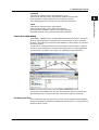
YOKOGAWA provides registered users with a variety of information and
services.
Please allow us to serve you best by completing the product registration
form accessible from our homepage.
http://tmi.yokogawa.com/
PIM 103-03E
Thank you for purchasing the GS610 Source Measure Unit.
This user’s manual contains useful information about the instrument’s functions and
operating procedures and lists the handling precautions of the GS610. To ensure
correct use, please read this manual thoroughly before beginning operation. After
reading the manual, keep it in a convenient location for quick reference whenever a
question arises during operation.
Manual Title
Manual No.
Description
GS610 Source Measure Unit
User’s Manual
IM 765501-01E
This manual. Explains all the functions of
the GS610 and their operating procedures.
Notes
• The contents of this manual are subject to change without prior notice as a result of
continuing improvements to the instrument’s performance and functions. The figures
given in this manual may differ from those that actually appear on your screen.
• Every effort has been made in the preparation of this manual to ensure the accuracy
of its contents. However, should you have any questions or find any errors, please
contact your nearest YOKOGAWA dealer.
• Copying or reproducing all or any part of the contents of this manual without the
permission of Yokogawa Electric Corporation is strictly prohibited.
• The TCP/IP software of this product and the document concerning the TCP/IP
software have been developed/created by YOKOGAWA based on the BSD
Networking Software, Release 1 that has been licensed from the University of
California.
Trademarks
• Microsoft, Internet Explorer, MS-DOS, Windows, Windows NT, and Windows XP are
either registered trademarks or trademarks of Microsoft Corporation in the United
States and/or other countries.
• Adobe, Acrobat, and PostScript are trademarks of Adobe Systems Incorporated.
• For purposes of this manual, the TM and ® symbols do not accompany their
respective trademark names or registered trademark names.
• Other company and product names are trademarks or registered trademarks of their
respective holders.
Revisions
• 1st edition: August 2005
• 2nd edition: January 2009
2nd Edition : January 2009 (YK)
All Rights Reserved, Copyright © 2005 Yokogawa Electric Corporation
IM 765501-01E
i
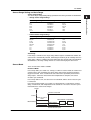
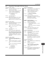
Checking the Contents of the Package
Unpack the box and check the contents before operating the instrument. If some of the
contents are not correct or missing or if there is physical damage, contact the dealer
from which you purchased them.
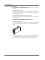
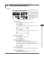
GS610
Check that the model name and suffix code given on the name plate on the side panel
match those on your order.
MODEL
MODEL
SUFFIX
SUFFIX
NO.
YOKOGAWA
NO.
YOKOGAWA
MODEL and SUFFIX Codes
Model
Suffix Code
765501
100-240 VAC
Power cord
-D
-F
-Q
-R
-H
Options
/C10
Description
UL/CSA Standard Power Cord (Part No.: A1006WD)
[Maximum rated voltage: 125 V; Maximum rated current: 7A]
VDE Standard Power Cord (Part No.: A1009WD)
[Maximum rated voltage: 250 V; Maximum rated current: 10 A]
BS Standard Power Cord (Part No.: A1054WD)
[Maximum rated voltage: 250 V; Maximum rated current: 10 A]
AS Standard Power Cord (Part No.: A1024WD)
[Maximum rated voltage: 250 V; Maximum rated current: 10 A]
GB Standard Power Cord (Part No.: A1064WD)
[Maximum rated voltage: 250 V; Maximum rated current: 10 A]
Ethernet interface
NO.(Instrument Number)
When contacting the dealer from which you purchased the instrument, please give them
the instrument number.
ii
IM 765501-01E
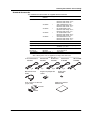
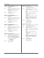
Checking the Contents of the Package
Standard Accessories
The standard accessories below are supplied with the instrument.
Name
Model
/Part No.
Qty.
Notes
Power cord
A1006WD
1
A1009WD
1
A1054WD
1
A1024WD
1
A1064WD
1
UL/CSA Standard Power Cord
Maximum rated voltage: 125 V;
Maximum rated current: 7A
VDE Standard Power Cord
Maximum rated voltage: 250 V;
Maximum rated current: 10 A
BS Standard Power Cord
Maximum rated voltage: 250 V;
Maximum rated current: 10 A
AS Standard Power Cord
Maximum rated voltage: 250 V;
Maximum rated current: 10 A
GB Standard Power Cord
Maximum rated voltage: 250 V;
Maximum rated current: 10 A
A9088ZM
2
Rubber Feet
Two rubber feet in one set
Measurement lead
758933
1
Alligator clip adapter
758922
1 set
Safety terminal-to-alligator clip adapter. Red
and black, 1 pc. each
D-sub connector for
External I/O
A1519JD/
B8060KA
1 set
1 connector cover, 1
15-pin connectocer
User’s Manual
IM765501-01E
1
This manual
One of these power cords is supplied according to the suffix code.
UL, CSA Standard
A1006WD
VDE Standard
A1009WD
D
Measurement Lead
758933
F
BS Standard
A1054WD
Q
Alligator Clip Adapter Set
758922
D-sub connector for EXT. I/O
(15-pin, male)
AS Standard
A1024WD
R
GB Standard
A1064WD
H
Rubber Feet
A9088ZM
GS610 User’s Manual
IM765501-01E
A1519JD
B8060KA
IM 765501-01E
iii
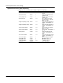
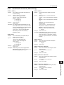
Checking the Contents of the Package
Optional Accessories (Sold Separately)
The optional accessories below are available for purchase separately.
iv
Name
Part Number
Minimum Q’ty
Notes
Measurement lead
758917
1
Measurement lead
758933
1
Safety adapter lead
701901
1
Banana plug set
758919
1 set
Alligator clip adapter (small) 758922
1 set
Alligator clip adapter (large) 758929
1 set
Safety terminal adapter
758923
1 set
Safety terminal adapter
758931
1 set
Safety mini-clip
701959
1 set
Fork terminal adapter
758921
1 set
Conversion adapter
Safety BNC cable
Safety BNC cable
D-sub connector for
External I/O
758924
701902
701903
A1519JD/
B8060KA
1
1
1
1 set
Safety terminal cable. Length:
0.75 m
Safety terminal banana male.
Length: 0.75 m
BNC-to-safety terminal cable
Length: 1.8 m
φ4 mm plug/φ4 mm socket
combined adapter. Red and
black, 1 pc. each
Safety terminal-to-alligator clip
adapter. Red and black, 1 pc.
each
Safety terminal-to-alligator clip
adapter. Red and black, 1 pc.
each
Spring clamp type. Red and
black, 1 pc. each
Screw-in type. Red and black, 1
pc. each
Safety terminal-to-mini clip
adapter. Red and black, 1 pc.
each
Safety terminal-to-fork terminal
adapter. Red and black, 1 pc.
each
BNC-to-binding post adapter
BNC-BNC, length: 1 m
BNC-BNC, length: 2 m
1 connector cover, 1
15-pin connectocer
IM 765501-01E
Safety Precautions
This instrument is an IEC safety class I instrument (provided with a terminal for
protective earth grounding).
The general safety precautions described herein must be observed during all phases of
operation. If the instrument is used in a manner not specified in this manual, the
protection provided by the instrument may be impaired. Yokogawa Electric Corporation
assumes no liability for the customer’s failure to comply with these requirements.
The following symbols are used on this instrument.
Warning: handle with care. Refer to the user’s manual or service manual.
This symbol appears on dangerous locations on the instrument which require
special instructions for proper handling or use. The same symbol appears in
the corresponding place in the manual to identify those instructions.)
Alternating current
ON (power)
OFF (power)
ON (power) state
OFF (power)
IM 765501-01E
v
Safety Precautions
Be sure to observe with the precautions below. Not complying might result in injury
or death.
WARNING
• Use the Correct Power Supply
Before connecting the power cord, ensure that the source voltage matches the
rated supply voltage of the instrument and that it is within the maximum rated
voltage of the provided power cord.
• Use the Correct Power Cord and Plug
To prevent the possibility of electric shock or fire, be sure to use the power cord
supplied by YOKOGAWA. The main power plug must be plugged into an outlet
with a protective earth terminal. Do not disable this protection by using an
extension cord without protective earth grounding.
• Connect the Protective Grounding Terminal
Make sure to connect the protective earth to prevent electric shock before
turning ON the power. The power cord that comes with the instrument is a
three-prong type power cord. Connect the power cord to a properly grounded
three-prong outlet.
• Do Not Impair the Protective Grounding
Never cut off the internal or external protective grounding wire or disconnect the
wiring of the protective grounding terminal. Doing so poses a potential shock
hazard.
• Do Not Operate with Defective Protective Grounding or Fuse
Do not operate the instrument if the protective earth or fuse might be defective.
Also, make sure to check them before operation.
• Do Not Operate in an Explosive Atmosphere
Do not operate the instrument in the presence of flammable liquids or vapors.
Operation in such an environment constitutes a safety hazard.
• Do Not Remove Covers
The cover should be removed by YOKOGAWA’s qualified personnel only.
Opening the cover is dangerous, because some areas inside the instrument
have high voltages.
• Ground the Instrument before Making External Connections
Securely connect the protective grounding before connecting to the item under
measurement or to an external control unit.
If you are going to touch the circuit, make sure to turn OFF the circuit and check
that no voltage is present.
vi
IM 765501-01E
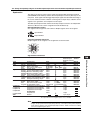
Waste Electrical and Electronic Equipment
Waste Electrical and Electronic Equipment (WEEE), Directive 2002/96/EC
(This directive is only valid in the EU.)
This product complies with the WEEE Directive (2002/96/EC) marking requirement. This
marking indicates that you must not discard this electrical/electronic product in domestic
household waste.
Product Category
With reference to the equipment types in the WEEE directive Annex 1, this product is
classified as a “Monitoring and Control instrumentation” product.
Do not dispose in domestic household waste. When disposing products in the EU,
contact your local Yokogawa Europe B. V. office.
IM 765501-01E
vii
Conventions Used in This Manual
Safety Markings
The following markings are used in this manual.
Improper handling or use can lead to injury to the user or damage
to the instrument. This symbol appears on the instrument to
indicate that the user must refer to the user’s manual for special
instructions. The same symbol appears in the corresponding place
in the user’s manual to identify those instructions. In the manual,
the symbol is used in conjunction with the word “WARNING” or
“CAUTION.”
WARNING
Calls attention to actions or conditions that could cause serious or
fatal injury to the user, and precautions that can be taken to prevent
such occurrences.
CAUTION
Calls attentions to actions or conditions that could cause light injury
to the user or damage to the instrument or user’s data, and
precautions that can be taken to prevent such occurrences.
Note
Calls attention to information that is important for proper operation
of the instrument.
Subheadings
On pages that describe the operating procedures in chapters 3 through 17 and appendix,
the following symbols are used to distinguish the procedures from their explanations.
Procedure
Follow the numbered steps. All procedures are written with
inexperienced users in mind; experienced users may not need to
carry out all the steps.
Explanation
This subsection describes the setup parameters and the limitations
on the procedures. It may not give a detailed explanation of the
function. For a detailed explanation of the function, see chapter 2.
<<Corresponding Command Mnemonic>>
Indicates a communication command that corresponds to the
function described on the procedural explanation page.
Displayed Characters and Terminology Used in the Procedural Explanations
Panel Keys and Rotary Knob
Bold characters used in the procedural explanations indicate characters that are marked
on the panel key or the rotary knob.
SHIFT+Key
SHIFT+key means you will press the SHIFT key to turn ON the SHIFT key followed by
the operation key. In this state, the items marked in purple characters below the keys
are controlled.
viii
IM 765501-01E
1
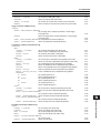
Contents
Checking the Contents of the Package ........................................................................................... ii
Safety Precautions ......................................................................................................................... v
Waste Electrical and Electronic Equipment ................................................................................... vii
Conventions Used in This Manual ................................................................................................ viii
Chapter 1 Part Names and Functions
1.1
1.2
1.3
1.4
Front Panel ...................................................................................................................... 1-1
Rear Panel ....................................................................................................................... 1-2
Names and Description of the Displayed Contents ......................................................... 1-3
Key Groups and Menus ................................................................................................... 1-5
Chapter 2 Explanation of Functions
2.1
2.2
2.3
2.4
2.5
2.6
2.7
2.8
2.9
2.10
System Configuration and Block Diagram ....................................................................... 2-1
Source Measure Cycle ..................................................................................................... 2-3
Source .............................................................................................................................. 2-5
Measurement ................................................................................................................. 2-10
Triggers .......................................................................................................................... 2-13
Sweep ............................................................................................................................ 2-14
Computation ................................................................................................................... 2-17
Store and Recall (Statistical Computation Value Display) .............................................. 2-19
USB Storage Function ................................................................................................... 2-20
Other Functions ............................................................................................................. 2-22
2
3
4
5
6
7
8
9
10
Chapter 3 Instrument Preparation and Common Operations
3.1
3.2
3.3
3.4
3.5
3.6
3.7
3.8
3.9
Handling Precautions ....................................................................................................... 3-1
Installing the GS610 ......................................................................................................... 3-3
Connecting to the Power Supply ...................................................................................... 3-6
Turning the Power Switch ON/OFF .................................................................................. 3-7
Wiring Precautions ........................................................................................................... 3-8
Setting the Power Frequency ........................................................................................... 3-9
Setting the Date, Time, and the Time Difference from GMT (Greenwich Mean Time) ... 3-10
Basic Operation of Keys and Rotary Knob .................................................................... 3-12
Entering Values .............................................................................................................. 3-14
Chapter 4 Trigger Setting, Connection Type (Remote Sense and Local Sense),
and USB Storage Function
4.1
4.2
4.3
Setting the Trigger ............................................................................................................ 4-1
Connection Type (Remote Sense and Local Sense) ....................................................... 4-3
USB Storage Function ..................................................................................................... 4-5
Chapter 5 Source
5.1
5.2
5.3
5.4
5.5
5.6
5.7
5.8
5.9
IM 765501-01E
Switching the Source Function ........................................................................................ 5-1
Setting the Source Range Setting .................................................................................... 5-2
Setting the Limiter ............................................................................................................ 5-4
Setting the DC Source Mode ........................................................................................... 5-6
Setting the Pulse Source Mode ....................................................................................... 5-8
Setting the Source Delay ............................................................................................... 5-11
Turning the Output ON/OFF ........................................................................................... 5-13
Zero Generation ............................................................................................................. 5-14
Offset Calibration ........................................................................................................... 5-16
ix
11
12
13
14
15
16
17
18
App
Index
Contents
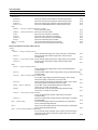
Chapter 6 Sweep
6.1
6.2
6.3
6.4
6.5
6.6
Setting the Linear or Log Sweep ...................................................................................... 6-1
Setting the Program Sweep ............................................................................................. 6-5
Selecting the Termination Mode ....................................................................................... 6-7
Setting the Repeat Count ................................................................................................. 6-9
Starting the Sweep Operation ........................................................................................ 6-10
Program Pattern File ...................................................................................................... 6-11
Chapter 7 Measurement
7.1
7.2
7.3
7.4
7.5
7.6
7.7
Turning the Measurement ON/OFF ................................................................................. 7-1
Selecting the Measurement Function .............................................................................. 7-2
Turning ON/OFF the Auto Range function of the Measurement Range Settings ............ 7-3
Setting the Measurement Delay ....................................................................................... 7-4
Setting the Integration Time ............................................................................................. 7-6
Auto Zero Function .......................................................................................................... 7-7
Turning Auto V/I ON/OFF ................................................................................................. 7-8
Chapter 8 Computation
8.1
8.2
8.3
8.4
8.5
Averaging ......................................................................................................................... 8-1
NULL Computation ........................................................................................................... 8-3
Computation Using Equations ......................................................................................... 8-4
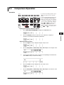
Comparison Operation ..................................................................................................... 8-7
User-Defined Computation .............................................................................................. 8-9
Chapter 9 Storing Measured Results and Recalling Statistical Computation
Values
9.1
9.2
Storing the Measured Results .......................................................................................... 9-1
Recalling Statistical Computation Values ......................................................................... 9-4
Chapter 10 BNC Input/Output and External Input/Output
10.1
10.2
Setting the Input/Output Signals of the BNC Input/Output Terminal and the External Input/
Output Connector ........................................................................................................... 10-1
Synchronized Operation ................................................................................................ 10-7
Chapter 11 Other Functions
11.1
11.2
11.3
11.4
11.5
11.6
11.7
11.8
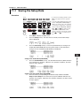
Saving the Setup Data ................................................................................................... 11-1
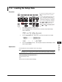
Loading the Setup Data ................................................................................................. 11-3
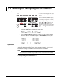
Selecting the Settings Applied at Power ON .................................................................. 11-4
Turning the Beep Sound ON/OFF .................................................................................. 11-5
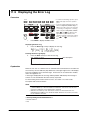
Displaying the Error Log ................................................................................................ 11-6
Selecting the Display Brightness and Turning the Display OFF .................................... 11-7
Key Lock ........................................................................................................................ 11-8
Selecting the Decimal Point and Separator Notations of CSV Files .............................. 11-9
Chapter 12 Ethernet Interface (Option)
12.1
12.2
12.3
12.4
12.5
x
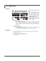
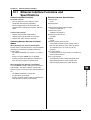
Ethernet Interface Functions and Specifications ............................................................ 12-1
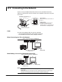
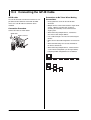
Connecting to the Network ............................................................................................. 12-2
Setting the TCP/IP ......................................................................................................... 12-3
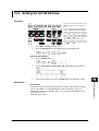
Checking the Ethernet Settings ..................................................................................... 12-6
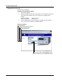
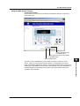
Web Server Function ..................................................................................................... 12-7
IM 765501-01E
Contents
1
Chapter 13 GP-IB Communications
13.1
13.2
13.3
13.4
13.5
About the IEEE.488.2-1992 Standard ............................................................................ 13-1
GP-IB Interface Functions and Specifications ............................................................... 13-3
Connecting the GP-IB Cable .......................................................................................... 13-4
Setting the GP-IB Address ............................................................................................. 13-5
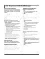
Responses to Interface Messages ................................................................................. 13-6
2
3
Chapter 14 RS-232 Communications
14.1
14.2
14.3
14.4
14.5
RS-232 Interface Functions and Specifications ............................................................. 14-1
Serial (RS-232) Interface Connection ............................................................................ 14-2
Handshaking Method ..................................................................................................... 14-4
Combination of Data Formats ........................................................................................ 14-5
Setting the RS-232 Interface .......................................................................................... 14-6
USB Interface Functions and Specifications .................................................................. 15-1
Selecting the USB Interface Function ............................................................................ 15-2
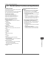
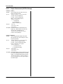
Chapter 16 Communication Commands
16.1
16.2
16.3
16.4
5
6
Chapter 15 USB Interface
15.1
15.2
4
Program Format ............................................................................................................. 16-1
16.1.1 Symbols Used in the Syntax ........................................................................... 16-1
16.1.2 Messages ........................................................................................................ 16-1
16.1.3 Commands ...................................................................................................... 16-3
16.1.4 Responses ...................................................................................................... 16-5
16.1.5 Data ................................................................................................................. 16-5
Commands ..................................................................................................................... 16-6
16.2.1 A List of Commands ........................................................................................ 16-6
16.2.2 Output Commands (OUTPut Group) ............................................................. 16-14
16.2.3 Source Commands (SOURce GRoup) .......................................................... 16-15
16.2.4 Sweep Commands (SWEep Group) ............................................................. 16-23
16.2.5 Measurement Commands (SENSe GRoup) ................................................. 16-24
16.2.6 Trigger Commands (TRIGger Group) ........................................................... 16-26
16.2.7 Computation Commands (CALCulate Group) ............................................... 16-27
16.2.8 Store/Recall Commands (TRACe Group) ..................................................... 16-29
16.2.9 External Input/Output Commands (ROUTe Group) ....................................... 16-31
16.2.10 System Commands (SYSTem Group) ........................................................... 16-34
16.2.11 Measured Value Read Commands (INITiate, FETCh, and READ Group) .... 16-38
16.2.12 Status Commands (STATus Group) .............................................................. 16-39
16.2.13 Common Command Group ........................................................................... 16-40
Status Reports ............................................................................................................. 16-42
16.3.1 Overview of the Status Report ...................................................................... 16-42
16.3.2 Status Byte .................................................................................................... 16-43
16.3.3 Standard Event Register ............................................................................... 16-44
16.3.4 Source Event Register .................................................................................. 16-46
16.3.5 Measure Event Register ................................................................................ 16-47
16.3.6 Output Queue and Error Queue .................................................................... 16-48
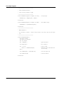
Sample Programs ........................................................................................................ 16-49
16.4.1 Before Programming ..................................................................................... 16-49
16.4.2 GP-IB Access Function ................................................................................. 16-50
16.4.3 Sample 1 (Example of Reading the Measured Results during Free Run Using
Internal Trigger) ............................................................................................. 16-53
7
8
9
10
11
12
13
14
15
16
17
18
App
Index
IM 765501-01E
xi
Contents
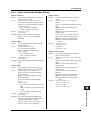
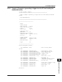
16.4.4
16.5
Sample 2 (Example of generating a trigger from the PC and reading the
measured results) ......................................................................................... 16-55
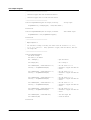
16.4.5 Sample 3 (Example of Updating the Source Level from a PC) ..................... 16-57
16.4.6 Sample 4 (Example of Updating the Source Level with the Sweep Function)
...................................................................................................................... 16-59
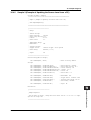
16.4.7 Sample 5 (Example of Carrying Out the Storage Function and Reading the
Statistical Values) .......................................................................................... 16-62
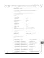
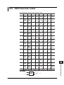
ASCII Character Codes ............................................................................................... 16-63
Chapter 17 Troubleshooting and Maintenance
17.1
17.2
17.3
17.4
17.5
17.6
Troubleshooting ............................................................................................................. 17-1
Error Code Description and Corrective Action ............................................................... 17-3
Self Test ......................................................................................................................... 17-6
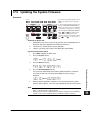
Checking the System Status .......................................................................................... 17-8
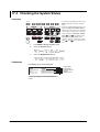
Updating the System Firmware ...................................................................................... 17-9
Recommended Replacement Parts ............................................................................. 17-11
Chapter 18 Specifications
18.1
18.2
18.3
18.4
18.5
18.6
18.7
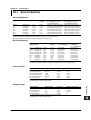
Source Section ............................................................................................................... 18-1
Measurement Section .................................................................................................... 18-3
Functions ....................................................................................................................... 18-4
External Input/Output Section (TRIG/SWEEP/CTRL IN and OUT) ................................ 18-5
Interface ......................................................................................................................... 18-5
General Specifications ................................................................................................... 18-6
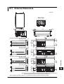
External Dimensions ...................................................................................................... 18-9
Appendix
Appendix 1 Computation Definition Specifications ................................................................ App-1
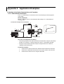
Appendix 2 Application Examples .......................................................................................... App-6
Appendix 3 Contents of the Factory Default Setup File (Default.txt) ................................... App-18
Index
xii
IM 765501-01E
Chapter 1
1.1
Part Names and Functions
1
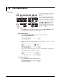
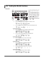
Front Panel
Part Names and Functions
2
Remote indicator
Illuminates when the GS610 is in remote mode (controlled via communications).
See sections 13.2 and 14.1.
3
KEY LOCK indicator
Illuminates when key lock is ON.
See section 11.7.
4
Remote sense indicator
Illuminates when remote sense (four-terminal connection).
See section 4.2.
Average indicator
Illuminates when averaging is ON. See section 8.1.
5
Display.
See section 1.3.
6
Soft keys
Used to select items on the soft key menu that appears
when setting up the GS610. See section 3.8.
7
GS610
SOURCE MEASURE UNIT
AVERAGE
4 WIRE
KEY LOCK
REMOTE
ESC
AUTO
RANGE
MENU
V I Ω
MODE
6
1
2
3
0
.
+-
MEASURE
MATH
NULL
COMPARE
VALUE
MENU
TIME
SWEEP
START
Hi
SHIFT
ZERO
110V
MAX
1V
MAX
TRIG
MODE
KEY LOCK
Lo
OUTPUT
110V
MAX
Output terminal
Connect the measurement lead that
comes with the package.
See sections 3.5 and 4.2.
9
10
ALL TERMINALS
250V MAX TO
11
12
Setup and execution keys
Power switch.
Keys used to change the settings or carry out an operation.
See section 3.4.
Press a setup key to show the respective setup item.
Handle
See sections 1.4 and 3.9.
Used when carrying the GS610.
See section 3.1.
SHIFT key
ESC (DISPLAY) key
Used to clear the soft key menu.
See section 3.8.
8
OUTPUT
SENSE
SOURCE
AUTO
RANGE
OUTPUT CONTROL
LOCAL
MISC
Rotary knob, numeric keys, and cursor
keys
Used to set values and select setup data
or items.
See sections 3.8 and 3.9.
VS IS
LIMIT
RANGE
POWER
9
5
SOURCE
MEASURE
RECALL
8
4
BS
DISPLAY
STORE
7
13
The keys enter the shifted state when you press the SHIFT key and
the SHIFT key illuminates. In this state, the items marked in purple
characters below the keys are controlled.
14
15
16
17
18
App
IM 765501-01E
1-1
Index
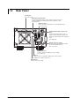
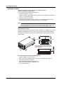
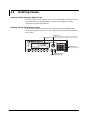
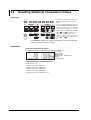
1.2
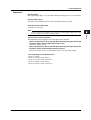
Rear Panel
Cooling fan.
See section 3.2.
BNC input/output terminal
Used to input/output signals such as trigger, sweep, and control
signals and deliver the output signal of the comparison result.
See chapter 10.
GP-IB connector
Used to perform communications via the GP-IB interface.
See section 13.3.
WARNING
Do not operate without reading the safety precautions in the user’s manual.
IN
GP-IB
(IEEE488)
EXT I O
TRIG /
SWEEP /
CTRL
OUT
ACT
ETHERNET
100BASE-TX
LINK
USB
External input/output connector (15
pins)
Used to input/output signals such as
trigger, sweep, and control signals and
deliver the output signal of the comparison
result.
See chapter 10.
100 - 120V 220 - 240V AC
200VA MAX 50 60Hz
SERIAL (RS-232)
RS-232 connector (9 pins)
Used to perform communications with a
PC via the RS-232 interface.
See section 14.2.
Power connector
Used to connect the GS610 to a power supply.
See section 3.3.
USB port
Used to connect to a PC with a USB interface when running
the GS610 as a USB storage device.
Ethernet port
Used to connect to a LAN.
1-2
IM 765501-01E
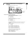
1.3
1
Part Names and Functions
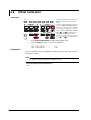
Names and Description of the Displayed
Contents
2
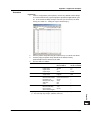
The contents shown on the display are as follows:
Status display area
Comparison result display
Trigger setting display
Source mode and sweep
mode displays
Wait indicator
3
High limiter indicator
Low limiter indicator
Sampling error indicator
Error indicator
4
5
Measured value
6
Source value
Source range
High limiter value
7
Low limiter value
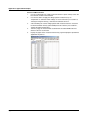
Information Shown in the Status Display Area
8
Comparison Result Display (For the procedures, see section 8.4)
Displays the judgement result of the comparison.
High: Over the upper limit
In:
Within the limits
Low: Under the lower limit
9
10
Trigger Mode Display (For the procedures, see section 4.1)
Displays the selected trigger mode.
Int:
Internal trigger
Ext:
External trigger
Imm: Immediate (no trigger wait)
11
12
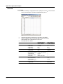
Source Mode and Sweep Mode Displays (For the procedures, see sections 5.4, 5.5,
6.1, and 6.2)
Displays the combination of the source mode and sweep mode. The following eight
combinations are available.
DC:
DC source
Pls:
Pulse source
DCLinr: Source mode = DC and sweep mode = Linear
DCLog: Source mode = DC and sweep mode = Log
DCProg: Source mode = DC and sweep mode = Program
PlsLinr: Source mode = pulse and sweep mode = Linear
PlsLog: Source mode = pulse and sweep mode = Log
PlsProg: Source mode = pulse and sweep mode = Program
13
14
15
16
17
Wait Indicator (For the procedures, see section 2.5 and 6.5)
Displays the various wait conditions during operation.
WaitTrigger: Waiting for trigger
WaitStart:
Waiting for sweep start
Calculating: Calculating sweep data
18
App
IM 765501-01E
1-3
Index
1.3 Names and Description of the Displayed Contents
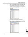
High Limiter Indicator (For the procedures, see section 5.3)
Turns ON when the high limiter is active.
Low Limiter Indicator (For the procedures, see section 5.3)
Turns ON when the low limiter is active.
Sampling Error Indicator (For the procedures, see section 2.5)
Turns ON when the trigger timing is not synchronized to the source measure cycle
period (the starting point) such as when a trigger is activated in the middle of a source
measure cycle.
Error Indicator (For the procedures, see section 11.5)
Turns ON when there is one or more errors in the error memory.
1-4
IM 765501-01E
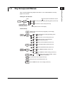
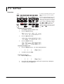
1.4
1
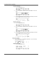
Key Groups and Menus
Pulse
Base
Sets the pulse base when generating pulses (section 5.2)
Part Names and Functions
Zero
Offset
Sets the zero source offset (section 5.8)
5
2
There are four functional key groups on the GS610. This section introduces each key
group in a tree format.
3
Viewing the Tree Structure
Setup description and reference section
Keys
VS IS
SHIFT
SOURCE
Activated when the
SHIFT key is pressed
followed by the key
4
6
Soft key menu shown on the display
SOURCE Group
7
VS IS
SOURCE
SHIFT
VS IS
SOURCE
Switches the source function (voltage (VS) or current (IS))
(section 5.1)
Pulse
Base
Sets the pulse base when generating pulses
(section 5.5)
Zero
Offset
Sets the zero source offset (section 5.8)
8
9
Switches the zero source impedance
Zero Z
Hiz Loz (high or low) (section 5.8)
LIMIT
MENU
SHIFT
LIMIT
MENU
MODE
Cal
Exec
Executes offset calibration (section 5.9)
High
Limit
Sets the upper limiter value (section 5.3)
Low
Limit
Sets the lower limiter value (section 5.3)
Limit
On Off
10
11
12
Turns ON/OFF the limiter (section 5.3)
Tracking Turns ON/OFF the limiter tracking (section 5.3)
On Off
SourceMode
DC
Pulse
13
Selects the source mode (DC or pulse)
(sections 5.4 and 5.5)
14
Increases the source range (section 5.2)
15
Decreases the source range (section 5.2)
AUTO
RANGE
Turns ON/OFF the auto source range (section 5.2)
16
17
18
App
IM 765501-01E
1-5
Index
1.4 Key Groups and Menus
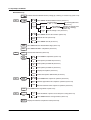
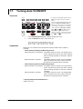
MEASURE Group
V I Ω
Switches the measurement function (voltage (V), current (I), or resistance (Ω) (section 7.2)
MEASURE
SHIFT
V I Ω
Measure
On Off
MEASURE
IntgTime
***
Average
***
Turns ON/OFF the measurement function (section 7.1)
IntegrationTime
Sets the integration time
250µs 1ms 4ms *** 100ms 200ms (section 7.5)
Mode
***
Count
***
AverageMode
Off Block Moving
Switches the average mode
(Off, Block, or Moving)
(section 8.1)
Sets the average count (section 8.1)
AutoZero
Turns ON/OFF the auto zero function (section 7.6)
On Off
AutoZero Execute auto zero (section 7.6)
Exec
Auto V/I
On Off
Turns ON/OFF auto V/I (section 7.7)
AUTO
RANGE
Turns ON/OFF the auto measurement range (section 7.3)
NULL
Turns ON/OFF the NULL computation (section 8.2)
VALUE
SHIFT
NULL
Sets the NULL reference (section 8.2)
VALUE
MATH
COMPARE
SHIFT
MATH
Math
On Off
Turns ON/OFF computation (section 8.3)
Param
A
Sets equation parameter A (section 8.3)
Param
B
Sets equation parameter B (section 8.3)
Param
C
Sets equation parameter C (section 8.3)
View
Displays the equation (section 8.3)
Select
File
Selects the equation definition file (section 8.3)
Compare
On Off
Turns ON/OFF the comparison operation (section 8.4)
COMPARE
STORE
Upper
Sets the upper limit of the comparison operation (section 8.4)
Lower
Sets the lower limit of the comparison operation (section 8.4)
Turns ON/OFF the storage function (section 9.1)
MENU
SHIFT
STORE
MENU
RECALL
1-6
Count
***
Auto
On Off
Sets the number of points to be stored (store count) (section 9.1)
Turns ON/OFF the auto storage function (section 9.1)
Displays the statistical computation result (section 9.2)
IM 765501-01E
1.4 Key Groups and Menus
1
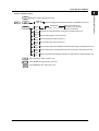
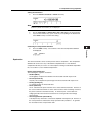
OUTPUT CONTROL Group
Part Names and Functions
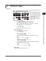
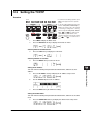
TRIG
Generates a manual trigger (section 4.1)
2
MODE
SHIFT
TRIG
Int
TrigMode
Ext Imm
Selects the trigger mode (internal, external, or immediate) (section 4.1)
3
MODE
SWEEP
Mode
***
Off
SweepMode
Linear Log Program
Selects the sweep mode
(off, linear, log, or program)
(sections 6.1 and 6.2)
4
Last
Switches the sweep termination mode (return on keep) (section 6.3)
Rtn Keep
Repeat
***
5
Sets the sweep repeat count (section 6.4)
Start
Value
Sets the sweep start value (section 6.1)
Stop
Value
Sets the sweep stop value (section 6.1)
Step
Value
Sets the sweep step value (displayed only when linear sweep is selected) (section 6.1)
Step
Count
Sets the sweep step count (displayed only when log sweep is selected) (section 6.1)
Select
File
Selects the pattern file (displayed only when program sweep is selected) (section 6.2)
6
7
8
START
Starts the sweep operation (section 6.5)
OUTPUT
Turns ON/OFF the output mode (section 5.7)
ZERO
Turns ON/OFF the zero state (section 5.8)
9
10
11
12
13
14
15
16
17
18
App
IM 765501-01E
1-7
Index
1.4 Key Groups and Menus
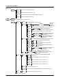
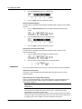
MISC Group
TIME
KEY LOCK
SHIFT
TIME
S.Delay
***
Sets the source delay (section 5.6)
M.Delay
***
Sets the measure delay (section 7.4)
Period
***
Sets the repeat period of the internal trigger (section 4.1)
P.Width
***
Sets the pulse width (section 5.5)
Turns ON/OFF key lock (section 11.6)
KEY LOCK
MISC
Remote
I/F
GPIB
***
RS232
Sets the GP-IB address (section 13.4)
BaudRate
***
DataBit
7 8
Parity
***
StopBit
1 2
Flow
***
Term
***
LAN
DHCP
On Off
BaudRate
9600 14400 19200 38400 57600 115200
Selects the
RS-232
baud rate
(section 14.5)
Switches the RS-232 data length (7 or 8) (section 14.5)
Parity
Selects the RS-232 parity
None Even Odd (none, odd, or even) (section 14.5)
Switches the RS-232 stop bit (1 or 2) (section 14.6)
Selects the RS-232 flow control
(none, XON-OFF, CTS-RTS)
(section 14.5)
Terminator
Selects the RS-232 transmission
CR LF CR+LF
delimiter (CR, LF, or CR+LF)
(section 14.5)
Turns ON/OFF the Ethernet DHCP function (section 12.3)
FlowControl
None XON CTS/RTS
IP
Address
Enter
Sets the fixed Ethernet IP address
(section 12.3)
Subnet
Mask
Enter
Sets the fixed Ethernet subnet mask
(section 12.3)
Default
Gateway
Enter
Sets the fixed Ethernet default gateway
(section 12.3)
Term
***
Terminator
CR LF CR+LF
Sets the Ethernet transmission
delimiter (CR, LF, or CR+LF)
(section 12.3)
Overview Shows a list of Ethernet settings (section 12.4)
USB
***
Setup
Save
Setup
Load
Setup
USB Mode
Selects the USB function (storage function
Storage USB-TMC or USB communication function)
(section 15.2)
Saves the settings to the RAM disk (GS610RAM)
Save
RamDisk (section 11.1)
Save
Setup1
Saves the settings to Setup 1 (section 11.1)
Save
Setup2
Saves the settings to Setup 2 (section 11.1)
Save
Setup3
Saves the settings to Setup 3 (section 11.1)
Save
Setup4
Saves the settings to Setup 4 (section 11.1)
Loads the setup (section 11.2)
PowerOn
Selects the setup used when the GS610 is powered up (section 11.3)
Setup
Error
Log
Clear
Shows and clears error log (section 11.5)
Continues to the next page
1-8
IM 765501-01E
1.4 Key Groups and Menus
1
Continued from the previous page
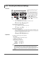
CSV
Setting
2
Selects sensing (two-wire or four-wire) (section 4.2)
DecPoint
.
Selects the decimal point for CSV files (section 11.8)
,
3
Separate
,
System
External
I/O
;
Selects the separator for CSV files (section 11.8)
BNC IN
Trig Sweep Ctrl
BNC IN
***
Selects the BNC input
(trigger, sweep start, or control) (section 10.1)
ControllType
IntLock Output Zero
DIO6
***
DIO7
***
DIO8
***
Display
***
Selects the BNC control input
(interlock, output relay control, or zero source) (section 10.1)
Selects the BNC output (trigger, sweep start, or control)
(section 10.1)
Selects the BNC trigger
output (trigger, source
TrigOutType
Type
change, measure begin,
Origin
ScrChg
MeasBgn
MeasEnd
PlsEnd
***
measure end, or falling
edge of pulse) (section 10.1)
Selects the BNC sweep synchronization output
SweepSyncOutType
Origin TurnEnd AllEnd (sweep start, 1 turn end, or all end)
(section 10.1)
ControlOutType
Selects the BNC control output
IntLock Output Zero Program (interlock, relay output, zero source,
or programmable) (section 10.1)
DIO 5pin
Selects the external input/output connector pin 5 function
Output Zero (output relay control or zero source control) (section 10.1)
Selects the external input/output
DIO 6pin(TrigOut)
connector pin 6 function (trigger, source
Origin ScrChg MeasBgn MeasEnd PlsEnd change, measure begin, measure end,
or pulse end) (section 10.1)
DIO 7pin(SweepSyncOut) Selects the external input/output connector pin 7 function
Origin TurnEnd AllEnd
(sweep start, 1 turn end, or all end) (section 10.1)
DIO 8pin(ControlOut)
Selects the external input/output connector pin 8 function
IntLock Output Zero
(interlock, output, or zero) (section 10.1)
DIO5
***
Beep
On Off
4
BNC OUT
Trig Sweep Ctrl
BNC OUT
***
Part Names and Functions
Wire
2W 4W
5
6
7
8
9
10
Turns ON/OFF the beep sound (section 11.4)
1
Bright
2 3 4
Off
Exec
11
Selects the display brightness (section 11.6)
Turns OFF the display (section 11.6)
12
LineFreq
Selects the power frequency (50 Hz or 60 Hz) (section 3.6)
50 60
Product
Info
Time
Adjust
Time
Zone
13
Shows the product information (section 17.4)
Edit
Edits the time (section 3.7)
Set
Sets the time (section 3.7)
Edit
Edits the GMT offset (section 3.7)
Set
Sets the GMT offset (section 3.7)
14
15
16
SelfTest
Disk
Format
Display
Executes the display test (section 17.3)
Key
Executes the key test (section 17.3)
Exec
Executes the GS610ROM disk format (section 4.3)
17
18
Firmware
Update Updates the system firmware (section 17.5)
App
IM 765501-01E
1-9
Index
Chapter 2
2.1
Explanation of Functions
1
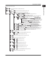
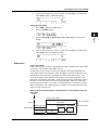
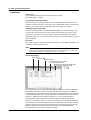
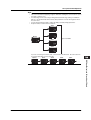
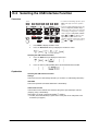
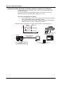
System Configuration and Block Diagram
2
System Configuration
Explanation of Functions
PC
• USB storage (store setup parameters,
recall statistical computation values, and
save/load equations, programs, and panel settings)
• Remote control
3
4
5
Trigger input
Sweep start input
Interlock input
Output ON/OFF (relay)
control input
Zero source control input
USB (USB storage)
Communication
(Ethernet, GP-IB, and RS-232*)
6
GS610
GS610
SOURCE MEASURE UNIT
7
POWER
Trigger output
Source change timing output
Source Measured value
Measure start timing output
(Voltage or current)
Measure end timing output
Pulse end timing output
DUT (device under test)
Sweep synchronization output
Sweep 1 turn end timing output
Sweep all end timing output
Interlock through output
Output ON/OFF (relay) status output
Zero source status output
* Conforms to EIA-574.
Programmable output
EIA-574 is an EIA-232 (RS-232) standard
Comparison result output
for the 9-pin interface.
Comparison end output
8
9
10
11
12
13
14
15
16
17
18
App
Index
IM 765501-01E
2-1
2.1 System Configuration and Block Diagram
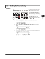
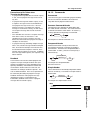
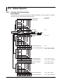
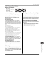
Block Diagram
CPU
Io
Source DAC
DUT
VFD
LO
Vo
Limiter DAC
KEY
Limiter
control
circuit
EXT I/O
Analog
control
HI
Current sense
amplifier
RS-232
GP-IB
Voltage sense amplifier
ADC
USB
ETHER
(option)
DUT: Device Under Test
Voltage Vo that appears across output terminals HI and LO is converted to normalized
voltage by a differential amplifier (voltage sense amplifier) that has different gains for
different voltage ranges. In addition, current Io that flows through output terminals HI
and LO is converted to normalized voltage by different shunt resistors and differential
amplifiers (current sense amplifiers) for different current ranges.
The analog section consists of the source block, limiter block, and measurement block.
The source block controls the voltage sense amplifier or the current sense amplifier so
that its output is equal to the source DAC output, and delivers the specified source value
across HI and LO. Two D/A converters are used in the source DAC to achieve a 5.5digit resolution.
The limiter control circuit in the limiter block controls the output across HI and LO so that it is
equal to the specified limiter value when the output from the voltage sense amplifier or
current sense amplifier exceeds the specified limiter value. When generating voltage, the
output from the current sense amplifier is compared with the limiter value; when generating
current, the output from the voltage sense amplifier is compared with the limiter value.
The measurement block measures the output from the voltage sense amplifier or current
sense amplifier. In addition, if the auto zero function is enabled, the internal zero
reference is measured every measurement cycle (measurement operation), and the
offset drift of the measurement pre-amplifier and A/D converter is cancelled while
measurements proceed. A feedback pulse width modulation (an integration type) is
employed for the A/D converter (ADC).
The analog control section transfers data to the D/A converter (DAC), controls various
switches, controls the width measurement of the pulse transferred from the A/D
converter, and so on. To achieve high-speed sweep of 100 µs steps, a high-speed
photocoupler is employed for the transferring of data to the source DAC.
The display employs a 256 × 64 dot VFD* to improve the visibility.
The GS610 comes with GP-IB and RS-232 interfaces that provide compatibility with
conventional systems as well as a USB port that is convenient for writing to or reading
data from a PC. An Ethernet port is also provided as an option if you wish to use the
existing network for data communication.
*
2-2
Vacuum Fluorescent Display
IM 765501-01E
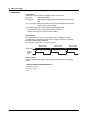
2.2
1
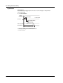
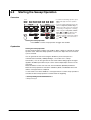
Source Measure Cycle
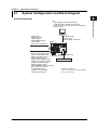
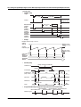
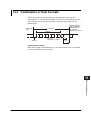
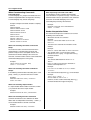
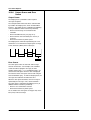
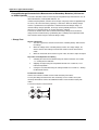
Source Measure Cycle Example
(When the Source Mode Is DC and Sweep Mode Is Linear)
2
Explanation of Functions
Source measure cycle on the GS610 refers to the basic operation that starts with a
trigger (see section 2.5, “Triggers”). When the GS610 output is ON, the source measure
cycle is constantly repeated.
In a source measure cycle, the source level changes after a time specified by the source
delay elapses from the point in which the trigger is activated. Furthermore, the
measurement starts after a time specified by the measurement delay elapses. When the
measurement and computation are complete, one source measure cycle is finished.
However, if you change the source level with a key or a communication command in the
middle of a source measure cycle, the source level changes immediately without waiting
for the source delay or measure delay, and the internal trigger phase is reset.
If the measurement function is turned OFF, measure delay, measurement, and
computation are not carried out. The way in which a source measure cycle ends varies
depending on the source mode (see sections 5.4, “DC Source Mode” and 5.5, “Pulse
Source Mode).
3
4
5
6
7
8
Trigger
9
Current source level
10
Source
Previous source
level
Measurement Computation
11
Measurement
Source delay
Measurement
delay
12
Source measure cycle
13
14
15
16
17
18
App
Index
IM 765501-01E
2-3
2.2 Source Measure Cycle
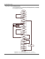
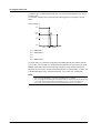
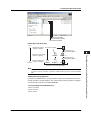
Flow Chart of a Source Measure Cycle
The time indicated in the chart is a typical time needed for its processing. The averaging
time varies depending on the average count, and the computation time varies depending
on the complexity of the equation.
Trigger
Source delay
+S. Delay
No
Range
mismatched when auto
source range is
selected?
Yes
Change source range
+3 ms
Update source level
+10 µs
Is measurement ON?
No
Yes
Measurement delay
+M. Delay
A/D operation
+IntgTime*
Change to optimal range
+2 ms
Yes
Range
mismatched when auto
measurement range
is selected?
No
No
Auto zero?
Yes
A/D operation
+IntgTime*
Zero compensation
Block average
operation?
No
Yes
No
Average count
finished?
Yes
Resistance
measurement?
No
Yes
Calculate resistance
+100 µs
Moving average (+moving
average count × 1.5 µs)
Computation
+150 µs
Computation
+150 µs
NULL computation
+20 µs
Comparison
+20 µs
End source
measure cycle
*
2-4
Integration time + 200 µs when the integration time is 250 µs, 1 ms, or 4 ms.
Integration time + 520 µs when the integration time is 20 ms, 100 ms, or 200 ms.
IM 765501-01E
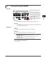
2.3
1
Source
2
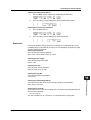
Source Function
Explanation of Functions
You can select voltage source (VS) or current source (IS).
3
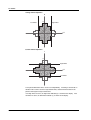
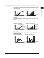
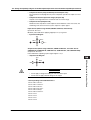
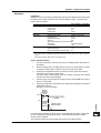
Source Range
The GS610 generates voltage or current in the range specified by the hatched lines in
the figure below. The performance limitations of the GS610 place constraints on the
current and voltage when generating voltage and current, respectively. For example, the
voltage is limited to 30 V or less when 1.5 A is specified when generating current. If the
voltage or current source level is at the boundary of the source range and is limited, a
high limiter indicator (H) illuminates if the level is positive and a low limiter indicator (L)
illuminates if the level is negative.
4
5
6
I
7
8
3.2
2
9
1
0.5
12
30
60
110
10
V
11
12
13
Limiter
14
CAUTION
15
If a load exceeding the source range above is connected such as a current
source exceeding the current limiter setting when generating voltage or a
voltage source exceeding the voltage limiter setting when generating current,
abnormal load is detected, and the output is turned OFF. Do not connect a load
exceeding the range above to the GS610. Doing so may cause malfunction.
16
17
If a limiter is set, an additional limit can be placed within the source range. This limit can
prevent damage to the connected device due to overcurrent or overvoltage. The current
limiter is automatically selected when generating voltage, and the voltage limiter is
automatically selected when generating current.
If the limiter is turned OFF, the voltage or current can be generated up to the maximum
value of the source range regardless of the limiter setting.
18
App
Index
IM 765501-01E
2-5
2.3 Source
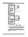
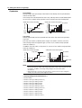
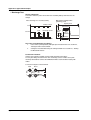
Voltage Limiter Operation
I
3.2
Low limiter
High limiter
2
1
0.5
12
30
60
110
V
Current Limiter Operation
I
3.2
2
High limiter
1
0.5
12
30
60
110
V
Low limiter
The high and low limiter values can be set independently. If tracking is turned ON, an
absolute value can be set for the high and low limits, and the limiter functions in the
positive and negative ranges around zero.
If the high limiter is active, the high limiter indicator (H) is shown on the display. If the
low limiter is active, the low limiter indicator (L) is shown on the display.
2-6
IM 765501-01E
2.3 Source
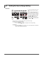
1
Source Range Setting and Auto Range
Source Range Setting
The source range settings during voltage generation and current generation are listed below.
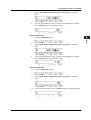
• Voltage Source Range Settings
2
Source Range Setting
Source Range
Resolution
200 mV
2V
12 V
20 V
30 V
60 V
110 V
±205.000 mV
±2.05000 V
±12.0000 V
±20.5000 V
±30.000 V
±60.000 V
±110.000 V
1 µV
10 µV
100 µV
100 µV
1 mV
1 mV
1 mV
Explanation of Functions
6
3
4
5
• Current Source Range Settings
Source Range Setting
Source Range
Resolution
20 µA
200 µA
2 mA
20 mA
200 mA
0.5 A
1A
2A
3A
±20.5000 µA
±205.000 µA
±2.05000 mA
±20.5000 mA
±205.000 mA
±0.50000 A
±1.00000 A
±2.00000 A
±3.20000 A
100 pA
1 nA
10 nA
100 nA
1 µA
10 µA
10 µA
10 µA
10 µA
7
8
9
Auto Range
If auto range is turned ON, the range setting with the highest resolution that contains the
source level is automatically selected, eliminating the need for you to manually select the
range setting. However, switching the range setting takes time, and the source level becomes
discontinuous, if the range setting switches as a result of changing the source level.
10
11
Source Mode
There are two source modes available.
DC Source Mode
If the sweep mode (see section 2.6, “Sweep”) is ON in DC source mode, the source level
changes after a time specified by the source delay elapses from the point in which the
trigger is activated. Then, measurement starts after a time specified by measurement
delay elapses. When the measurement and computation are complete, one source
measure cycle is finished.
If the sweep mode is OFF, the source level is maintained, and the source measure cycle
is carried out.
If the measurement function (see section 2.4, “Measurement”) is turned OFF, measure
delay, measurement, and computation are not carried out. The source measure cycle is
finished when the source level changes.
12
13
14
15
16
Trigger
17
Current source level
18
Source
Previous source
level
Measurement Computation
App
Measurement
Source delay
Measurement
delay
Index
Source measure cycle
IM 765501-01E
2-7
2.3 Source
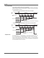
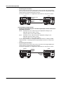
Pulse Source Mode
Pulse source mode can be used to improve the reproducibility of measurements on
DUTs that change in characteristics due to the heat generation that results from applying
the source such as a resistor with large temperature coefficient. It is also effective for
evaluation of display devices that use pulse width to control the brightness.
The pulse is specified by two values, the pulse base value and the source level. The
minimum pulse width is 100 µs.
As with the DC source, the source level changes after a time specified by the source
delay elapses from the point in which the trigger is activated. Furthermore, the
measurement starts after a time specified by the measurement delay elapses. The
source level changes at the same the measure delay is activated and returns to the
pulse base value after the pulse width. A source measure cycle is finished at the end of
the pulse or at the end of the measurement and computation, whichever comes later.
If the measurement function (see section 2.4, “Measurement”) is turned OFF, measure
delay, measurement, and computation are not carried out. The end of the pulse is the
end of a source measure cycle.
When the End of the Measurement and Computation Is after the End of the Pulse
Generation
Trigger
Current source level
Pulse source end
Pulse width
Source
Base pulse value
Measurement Computation
Base pulse value
Measurement
Source delay
Measurement
delay
Source measure cycle
When the End of the Measurement and Computation Is before the End of the Pulse
Generation
Trigger
Current source level
Pulse width
Source
Base pulse value
Measurement
Source delay
Pulse source end
Base pulse value
Measurement
delay
Measurement
Computation
Source measure cycle
Source Delay
The source delay specifies the wait time at which the source value is actually changed
after the trigger is activated. It is typically used as a trigger delay when an external
trigger is used.
The source delay can be set in the range of 1 µs to 3600 s. However, setting a long
source delay results in a long source measure cycle. Set the smallest value possible.
2-8
IM 765501-01E
2.3 Source
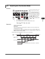
1
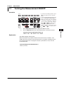
Turning the Output ON/OFF and Generating Zero Output
As shown in the figure below, there are three output modes, Output ON, Output OFF,
and Zero Generation. The mode is switched with the OUTPUT and ZERO keys.
2
Explanation of Functions
Output
ON
3
OUTPUT
OUTPUT
Output
OFF
4
OUTPUT
illuminates
ZERO
5
ZERO
OUTPUT
SHIFT
6
ZERO
Zero
output
Output OFF:
Output ON:
Zero Generation:
7
ZERO
illuminates
8
The output relay is OFF, and voltage or current is not generated.
The source measure cycle is also stopped.
The output relay is ON, and voltage or current is generated. The
source measure cycle is repeated.
The output relay is ON. If generating voltage, 0 V is generated. If
generating current, 0 A is generated. Then, the source measure
cycle is stopped.
9
10
Zero Source Offset
An offset can be specified on the zero value when generating zero output.
11
Zero Source Impedance
Low impedance (LoZ) is default when generating voltage, and high impedance (HiZ) is
default when generating current. Only the source value is set to zero.
If high impedance is set when generating voltage or low impedance is set when
generating current, the source value is set to zero, and the limiter is constrained to the
minimum value of the range.
12
Offset calibration can be used to correct the drift in the zero point of the source value
such as due to temperature change. For example, the offset calibration is used to
correct the offset fluctuation due to the leak current of the internal circuit when using a
low current source range in a high temperature environment.
15
13
14
Offset Calibration
16
17
18
App
Index
IM 765501-01E
2-9
2.4
Measurement
Turning the Measurement Function ON/OFF
If measurement is not necessary, the measurement function can be turned OFF. When
the measurement function is turned OFF, the procedure related to measurement is not
carried out. This enables the source measure cycle to be shortened.
Measurement Function
You can select voltage measurement (V), current measurement (I), or resistance
measurement (Ω).
In resistance measurement, current is measured when voltage is generated, and voltage
is measured when current is generated. Then, the resistance is derived by calculating
voltage/current.
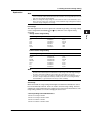
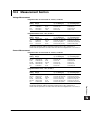
Measurement Range Setting and Auto Range
The measurement range settings during voltage measurement and current measurement
are listed below. However, the measurement range setting is not directly specified, but
determined indirectly by the source range setting and limiter setting.
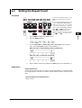
• Voltage Measurement Range Settings
Integration Time of 16.66 ms/20 ms, 100 ms,
or 200 ms
Range
Measurement
Resolution
Setting
Range
Integration time of 4 ms, 1 ms, or 250 ms
Range
Setting
Measurement
Range
Resolution
200 mV
2V
20 V
110 V
200 mV
2V
20 V
110 V
±205.00 mV
±2.0500 V
±20.500 V
±110.00 V
10 µV
100 µV
1 mV
10 mV
±205.000 mV
±2.05000 V
±20.5000 V
±110.000 V
1 µV
10 µV
100 µV
1 mV
When Generating Current
Same as the voltage limiter range
When Generating Voltage
Same as the voltage source range
However, if the voltage source range is 12 V, 30 V, or 60 V, the settings below apply.
Voltage Source Range Setting
Voltage Measurement Range Setting
12 V
30 V
60 V
20 V
110 V
110 V
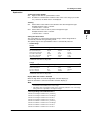
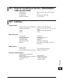
• Current Measurement Range Settings
2-10
Integration Time of 16.66 ms/20 ms, 100 ms,
or 200 ms
Range
Measurement
Resolution
Setting
Range
Integration time of 4 ms, 1 ms, or 250 ms
Range
Setting
Measurement
Range
Resolution
20 µA
200 µA
2 mA
20 mA
200 mA
3A
20 µA
200 µA
2 mA
20 mA
200 mA
3A
±20.500 µA
±205.00 µA
±2.0500 mA
±20.500 mA
±205.00 mA
±3.2000 mA
1 nA
10 nA
100 nA
100 nA
10 µA
100 µA
±20.5000 µA
±205.000 µA
±2.05000 mA
±20.5000 mA
±205.000 mA
±3.20000 A
100 pA
1 nA
10 nA
100 nA
1 µA
10 µA
IM 765501-01E
2.4 Measurement
Current Source Range Setting
Current Measurement Range Setting
0.5 A
1A
2A
3A
3A
3A
1
2
Explanation of Functions
When Generating Voltage
Same as the current limiter range
When Generating Current
Same as the current source range
However, if the current source range is 0.5 A, 1 A, or 2 A, the settings below apply.
3
4
Auto Range
When auto range is turned ON, the GS610 makes a measurement and checks whether a
different range setting is available for making the measurement with the best resolution.
If there is, the GS610 changes the range setting and makes the measurement again.
However, it may take time for the GS610 to switch the range setting, and the source
level may become discontinuous.
5
6
7
Measurement Delay
The measurement delay is the wait time at which the measurement is started after the
source level is switched. It is used for the item being measured to stabilize.
The measurement delay can be set in the range of 1 µs to 3600 s. However, setting a
long measurement delay results in a long source measure cycle. Set the smallest value
possible.
8
9
10
Integration Time
The integration time is the time that the integrating A/D converter performs integration. If
you increase the integration time, the time needed to make measurements takes longer,
but the measured values are more stable.
When the power frequency is 50 Hz: 250 µs, 1 ms, 4 ms, 20 ms, 100 ms, or 200 ms
When the power frequency is 60 Hz: 250 µs, 1 ms, 4 ms, 16.6 ms, 100 ms, or 200 ms
If the integration time is set to 200 ms, 100 ms, 20 ms, or 16.6 ms, the effects of noise
from the power frequency can be eliminated, because these settings are integer
multiples of the power cycle.
11
12
13
14
Auto Zero Function
When auto zero is ON, the GS610 also measures the internal zero reference for each
measurement. The measured result is obtained by subtracting this value from the
measured value canceling the offset drift of the measurement circuit in the GS610.
However, the measurement takes approximately twice as long, because the GS610
measures twice.
15
16
17
18
App
Index
IM 765501-01E
2-11
2.4 Measurement
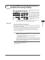
Auto V/I
This function enables the measurement function to be switched when a limiter is
activated.
For example, when a secondary battery is being charged with constant current, the rising
battery voltage can be measured. When the voltage limiter is activated and the
operation switches to constant voltage charge, the reduction in the charging current can
be measured.
When Generating Voltage and Measuring Current
When the limiter is not activated: The GS610 measures current. The voltage source
level is entered for the source value in the result file
when the storage operation is carried out. (Normal
operation)
When the limiter is activated:
The GS610 measures voltage. The current limiter
value is entered for the source value in the result file
when the storage operation is carried out.
When Generating Current and Measuring Voltage
When the limiter is not activated: The GS610 measures voltage. The current source
level is entered for the source value in the result file
when the storage operation is carried out. (Normal
operation)
When the limiter is activated:
The GS610 measures current. The voltage limiter
value is entered for the source value in the result file
when the storage operation is carried out.
2-12
IM 765501-01E
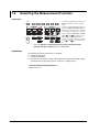
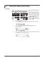
2.5
1
Triggers
When the GS610 is waiting for a trigger (when the source measure cycle is complete),
the wait indicator on the display shows “WaitTrigger.” If a trigger is activated, the TRIG
key on the front panel blinks, and WaitTrigger of the wait indicator is turned OFF until the
source measure cycle is complete.
When using an external trigger, manual trigger using the TRIG key on the front panel
and triggers activated with communication commands (“*TRG” or GroupExecuteTrigger)
are valid.
If you wish to activate triggers only with communication commands, select external
trigger and do not apply triggers to the BNC input/output terminal or pin 2 on the external
input/output connector on the rear panel.
2
Explanation of Functions
The following three triggers are available for starting a source measure cycle.
Internal trigger (Int): The internal constant period timer is used as triggers. The cycle
can be set in the range of 100 µs to 3600 s.
External trigger (Ext): The rising edge of the voltage signal that is applied to the BNC
input/output terminal or pin 2 on the external input/output
connector on the rear panel is used as a trigger.
Immediate (Imm):
The GS610 does not wait for a trigger. When the current source
measure cycle is complete, the next source measure cycle starts
immediately. This trigger can be selected only when the
measurement function is ON.
3
4
5
6
7
8
9
10
Note
If another trigger is activated in the middle of a source measure cycle, that trigger is
discarded. If the trigger timing is not synchronized to the source measure cycle period (the
starting point) as in this case, the sampling error indicator (SampleErr) illuminates in the
status display area of the display.
To prevent sampling errors from occurring, increase the interval at which triggers are
activated or shorten the source measure cycle (see section 2.2, “Source Measure Cycle”).
Below are ways of shortening the source measure cycle.
• Set the shortest source delay and measurement delay possible.
• If measurements are not needed, turn the measurement function OFF. When making
measurements, set the shortest integration time possible.
• Turn OFF the auto zero function (see section 2.4, “Measurement”).
• Turn OFF the auto range function of the source and measurement range settings.
• Turn OFF various computation functions.
• When performing a sweep, turn OFF the auto storage function (see section 2.8, “Store/
Recall”).
11
12
13
14
15
16
17
18
App
Index
IM 765501-01E
2-13
2.6
Sweep
There are three sweep modes, linear sweep, log sweep, and program sweep. To
disable the sweep function, turn it OFF. The sweep key illuminates when the sweep
mode is not OFF.
Basic Sweep Operation
The sweep function repeats the source measure cycle by automatically varying the
source level. In this case, a start event is needed for starting the sweep operation in
addition to the trigger that starts the source measure cycle.
The sweep function starts in a start-wait condition. The GS610 can receive triggers only
after receiving a start event. Once started, the GS610 repeats the source measure cycle
by varying the source level for the subsequent triggers that it receives. When a sweep
operation is completed, the GS610 transits to the start-wait condition again.
Basic Sweep Operation
Start
Sweep state Waiting for start
Sweeping
Trigger
Source measure
cycle (first)
2-14
Waiting for start
Trigger
Source measure
cycle (last)
IM 765501-01E
2.6 Sweep
1
Sweep Mode
Linear Sweep
Sweeps using evenly spaced step values that increase linearly from the specified start
value to the stop value.
• When the source mode is pulse
Source level
Source level
Stop value
Start value
Initial
value
Step value
Start
3
Stop value
Step value
4
Start value
Initial
value Start
Trigger count
Base value
Trigger count
7
8
• When the source mode is pulse
Stop value
Stop value
Step count
Start value
Trigger count
Start
Source level
Source level
Initial
value
5
6
Log Sweep
Sweeps exponentially from the specified start value to the stop value at the specified
step count.
The step count can be set arbitrary in the range of 2 to 65535. However, if the start
value and stop value have opposite signs, an error occurs, and the sweep operation
cannot be carried out.
• When the source mode is DC
Explanation of Functions
• When the source mode is DC
2
Initial
value
9
Step count
10
Start value
Base value
Trigger count
Start
Program Sweep
Sweeps according to the values in a pattern file containing an arbitrary sweep pattern.
11
12
Program Sweep Example
• When the source mode is DC
Source level
Source level
Initial
value
Start
13
• When the source mode is pulse
Trigger count
Initial
value
14
15
Base value
Trigger count
16
Start
17
18
App
Index
IM 765501-01E
2-15
2.6 Sweep
Termination Mode
There are two termination modes, Keep and return (Rtn).
In Keep mode, the last source level of the sweep operation is retained. In Return (Rtn)
mode, the source level after the sweep operation is complete is reset to the level before
the sweep operation was started.
• Sweep operation when the termination mode (Last) is set to keep
Start
Sweep
state
Sweeping
Waiting for start
Trigger
Source measure
cycle
Trigger
Trigger
Trigger
Waiting for start
Trigger
Sd Meas Sd Meas Sd Meas Sd Meas Sd Meas
Stop value
Source level
Start value
Source level
before sweep
Sd: Source delay
Meas: Measurement delay + measurement + computation
• Sweep operation when the termination mode (Last) is set to return (Rtn)
Start
Sweep
state
Waiting for start
Sweeping
Trigger
Source measure
cycle
Trigger
Trigger
Trigger
Waiting for start
Trigger
Trigger
Sd Meas Sd Meas Sd Meas Sd Meas Sd Meas Sd
Stop value
Source level
Start value
Source level
before sweep
Sd: Source delay
Meas: Measurement delay + measurement +
computation
Repeat Count
The selectable range is 1 to 1000 or infinity (∞). For example, if the repeat count is set
to 5, the GS610 repeats the sweep operation five times when it receives a start event.
Then, the GS610 returns to the start-wait condition. If infinity (∞) is selected, the GS610
starts the sweep operation when it receives a start event and repeats the operation until
the sweep operation or output is turned OFF.
2-16
IM 765501-01E
2.7
1
Computation
2
Averaging
Display value =
1
×
AVerageCount
Explanation of Functions
When the averaging function is used, the specified number (average count) of measured
values are averaged to derive the final displayed value. Therefore, the measured results
are more stable.
There are two averaging modes, block average and moving average.
Block average: The specified average count of measurements is carried out in a single
source measure cycle. The GS610 displays the result obtained by
summing the measured values and dividing the sum value by the
average count. Therefore, the measurement time takes average count
times as long.
Moving average: The GS610 measures once in a single source measure cycle. The
GS610 displays the result obtained by summing the average count of
measured values and dividing the sum value by the average count. If
the number of measurements does not reach the average count, the
average over the number of measurements is displayed.
3
4
5
6
7
AVerageCount
Σ
8
Measured value [i]
i=1
The average count can be set in the range of 2 to 256.
When the averaging function is enabled, the average indicator on the left side of the
GS610 illuminates.
9
10
NULL Computation
In NULL computation, a difference with respect to a given value can be displayed. The
NULL value is set to the measured value when the NULL computation is turned ON.
From that point, the GS610 displays the results obtained by subtracting the NULL value
from the measured values.
11
12
Displayed value = Measured value – NULL value
When the NULL computation is switched from OFF to ON, the measured value at that
point is automatically entered as the NULL value. However, this value can be changed
afterwards.
When the NULL computation is enabled, the NULL key illuminates.
13
14
Computation Using Equations
Computation can be performed using equations provided in a text file. In computation
using equations, four arithmetic operations, trigonometric functions, and so forth can be
performed on variables such as source values and measured values as well as
constants.
For example, if an equation “m=I*V” is applied, the GS610 calculates and displays the
power.
The equation can be selected from the definition files in the MATH directory on the
internal GS610 ROM disk (see section 2.9, “USB Storage Function). For the definitions
files, you can use built-in computation files that are available when the GS610 is shipped
from the factory (or when the disk is formatted (see section 4.3, “USB Storage Function”)
and user-defined computation files that you create such as on a PC.
If the definition file contains an equation with variables A, B, and C, the values for A, B,
and C can be entered from the GS610 panel soft keys. Computation using equations
can be used not only to perform computation using measured values, but also to create
the next source value from the calculation.
IM 765501-01E
2-17
15
16
17
18
App
Index
2.7 Computation
The following five equations are available as built-in computation.
• Decibel (dB.txt)
m=A*log(m/B): Computes the decibel of the measured value with respect to B.
• Percent (Percent.txt)
m=(m/A)*100: Computes the percentage of the measured value with respect to A.
• Scaling (Scaling.txt)
m = A*M+B: Scales the measured value.
• Power (Power.txt)
m=V*I: Calculates the power from the source value and measured value. However, if
the source and measurement are of the same function or when measuring resistance,
the power cannot be calculated correctly. To measure power, set the GS610 to
voltage generation and current measurement or current generation and voltage
measurement.
• Sinusoid generation (Sinusoid.txt)
s=A*sin(2*PI*B*t): Generates a sinusoid of amplitude A and frequency B. However, if
the sweep function is enabled, the sweep operation takes precedence. To generate
the sinusoid, turn the sweep function OFF.
When computation using equations is turned ON, the MATH key illuminates. For details
on the syntax and operators of equations in the definition files, see appendix 1.
Comparison Operation
The measured value is compared with the upper and lower limits specified by the user
and divided into three groups, over the upper limit (High), within the limits (In), and under
the lower limit (Low). The result of the grouping is displayed at the upper left corner of
the status display area on the display and output to the external input/output connector.
For a description of the external input/output, see section 10.1, “Setting the Input/Output
Signal on the BNC Input/Output Terminal and External Input/Output Connector.”
When the comparison operation is turned ON, the MATH key illuminates.
2-18
IM 765501-01E
2.8
1
Store and Recall (Statistical Computation
Value Display)
2
Storage Operation
When you press the STORE key, the storage operation starts and the STORE key
illuminates. Then, when the store count of source measure cycles is complete, the
storage operation automatically ends, and the result file (Result.csv) is created.
If you press the STORE key while the storage operation is in progress, the storage
operation is stopped, and the contents stored up to that point is saved to the result file
(Result.csv).
The store count can be set in the range of 1 to 65535.
Explanation of Functions
This function stores up to 65535 points of the results of the source measure cycle in the
store memory. The contents of the store memory is output to the internal GS610RAM as
a result file (Result.csv) after the storage operation is complete. The contents output to
the result file are arrays of elapsed times from the store start point, source values,
measured values, and setting changes during the sweep operation.
3
4
5
6
7
Auto Storage
The auto storage function automatically starts the storage operation with the start of the
sweep operation. The store count in this case is automatically set to the sweep repeat
count. However, if the sweep repeat count exceeds 65535, the store count is set to
65535.
Recall
8
9
10
When you carry out a recall operation, the statistical computation results of the
measured values in the store memory can be retrieved. The statistical computation
parameters are the store count, minimum value, maximum value, maximum value –
minimum value, average value, and standard deviation.
11
12
13
14
15
16
17
18
App
Index
IM 765501-01E
2-19
2.9
USB Storage Function
The GS610 has a built-in 4-MB non-volatile disk (GS610ROM) and a 4-MB volatile disk
(GS610RAM). If the GS610 is connected to a PC with a USB cable, these disks can be
accessed from the PC as removable disks.
Non-Volatile Disk (GS610ROM)
GS610ROM is a non-volatile disk that retains the data on the disk even when the power
is turned OFF. It contains three directories, MATH, PROGRAM, and SETUP. Equation
definition files, program sweep files, and so forth can be stored on this disk to be used on
the GS610.
MATH
A directory for storing the definition files of equations.
The files in this directory can be selected for the computation using equations.
By factory default, built-in computation files are stored in this directory.
The built-in computation files are not erased even if the disk is formatted.
2-20
IM 765501-01E
2.9 USB Storage Function
1
PROGRAM
A directory for storing the pattern files of program sweeps.
The files in this directory can be selected for the program sweep function.
By factory default, sample program files are stored in this directory.
The sample program files are not erased even if the disk is formatted.
2
Explanation of Functions
3
SETUP
A directory for storing the GS610 panel settings.
The files in this directory can be selected as setup files.
By factory default, a default setup file is stored in this directory.
The default setup file is not erased even if the disk is formatted.
4
5
Volatile Disk (GS610RAM)
GS610RAM is a RAM disk that is automatically formatted when the power is turned ON.
When the storage operation is carried out, the result file (Result.csv) file is created on
this disk. If the settings are saved to the GS610RAM, the current settings are saved to a
file named Setup.txt.
This directory is usually used to pass files that the GS610 creates to the PC. However,
this disk is also used to write the system file (System.bin) from a PC when updating the
system firmware. For details, see section 17.5, “Updating the System Firmware.”
6
7
8
9
10
11
12
13
14
15
You can also create subdirectories and write files to this disk, but be sure that the disk
does not become full. The data on this disk is lost when the power is turned OFF.
Formatting the Disk
You can format the disk when you wish to reset the GS610 to factory default conditions,
when the non-volatile or volatile disk cannot be detected on your PC, or if you believe the
data on the disk is corrupt.
16
17
18
App
Index
IM 765501-01E
2-21
2.10 Other Functions
Sensing
The GS610 has two types of sensing connections, 2W (two-terminal connection = local
sense) and 4W (four-terminal connection = remote sense). You can select the
appropriate sensing connection according to the amplitude of the output current.
Four-terminal connection reduces the effects of the voltage drop due to the output
current and lead resistance.
BNC Input/Output and External Input/Output
The GS610 has a BNC terminal (TRIG/SWEEP/CTRL IN/OUT) and external input/output
connector (EXT I/O) that can be used to input or output trigger signals and other signals
and output the comparison results.
GP-IB/RS-232 Communication
The GS610 is equipped with a GP-IB interface and RS-232 interface that can be used to
control the GS610 using commands.
On the RS-232 interface, various parameters such as baud rate (9600 bps to 115200
bps), flow control (none, XON-OFF, or CTS-RTS), and terminator (CR, LF, or CR+LF).
The command control using the GP-IB, RS-232, and the optional Ethernet interface are
mutually independent, and can be used simultaneously. For example, the GS610 can be
controlled via the GP-IB interface while monitoring the status via the Ethernet interface.
Ethernet Communications (Option)
A LAN interface with auto switching between 10 Mbps and 100 Mbps.
In addition to controlling the GS610 using commands, up to five FTP clients can be
connected through the anonymous FTP server function. The non-volatile disk
(GS610ROM) and volatile disk (GS610RAM) are available as subdirectories at the FTP
root. Files can be transferred freely using the FTP protocol.
You can set a fixed address for the IP address or obtain the address dynamically from
the DHCP server.
Command control server function: A command mnemonic stream parsing server at port
7655 that allows up to five clients to connect.
The terminator (CR, LF, or CR+LF) can be specified.
FTP server function:
An anonymous FTP server at port 21 that allows up
to five clients to connect.
HTTP server function:
A function that enables various information to be
displayed and performs remote control of the GS610
through port 80 using a Web browser.
Each server function is independent. Therefore, for example, the GS610 can be
controlled using commands while transferring files using FTP.
Saving/Loading Setup Data
The current settings can be saved to a setup file (Setup1.txt to Setup4.txt) on the nonvolatile disk (GS610ROM). The saved setup data can be loaded to restore the settings.
The setup data can also be saved to the volatile disk (GS610RAM). This feature can be
used to pass the setup file (Setup.txt) to a PC.
The setup file is a text file containing communication commands. The file can be edited
later on a PC.
2-22
IM 765501-01E
2.10 Other Functions
1
Setting at Power ON
Error Log Display
The GS610 stores up to 127 runtime errors and command errors in the error memory. If
one or more errors exist in the error memory, the error indicator (Err) at the upper right of
the screen illuminates.
Turing ON/OFF the Beep Sound
You can select whether the GS610 generates a beep sound when you operate the
GS610 incorrectly, when an error occurs during operation, or when the computation is
turned ON.
2
Explanation of Functions
The GS610 settings at power on can be changed from the default settings to the settings
selected by the user. If one of the saved setup files is selected as the settings at power
on, the GS610 starts up using the specified settings from the next time the GS610 is
powered ON.
If the selected file is deleted or renamed, the GS610 starts up with default settings.
3
4
5
6
7
Setting the Display Brightness or Turning OFF the Display
You can set the brightness of the display. You can turn OFF the display to prolong the
service life of the display.
Key Lock
8
9
You can lock the panel keys so that the settings are not changed inadvertently.
10
Selecting the Decimal Point and Separator Notations of CSV Files
You can select the decimal point (period or comma) and the separator (comma or
semicolon) notations according to the Excel program that you use. The selected
notation is applied to program pattern files and measurement result files in CSV format.
Self Test
11
12
You can test the display and keys.
13
Checking the System Status
The GS610 displays the product name, serial number, firmware version, options, and
calibration date.
14
Updating the System Firmware
The GS610 system can be updated by storing the most recent system file from a PC to
the volatile disk (GS610RAM).
15
16
17
18
App
Index
IM 765501-01E
2-23
Chapter 3
3.1
Instrument Preparation and Common Operations
1
Handling Precautions
2
Read the Safety Precautions
Safety Precautions
If you are using this instrument for the first time, make sure to thoroughly read “Safety
Precautions” given on pages v and vi.
3
Unplug If Abnormal Behavior Occurs
If you notice smoke or unusual odors coming from the instrument, immediately turn OFF
the power and unplug the power cord. If these symptoms occur, contact your nearest
YOKOGAWA dealer.
Correct the Problem If Output Is Forcibly Turned OFF
If the GS610 detects an internal circuit error due to an excessive external input or
oscillation in the GS610, the GS610 forcibly turns OFF the output and displays an error.
If this happens, remove the cause of the problem such as the load connected externally,
and turn the output ON again. If the output still turns OFF after correcting the problem,
the GS610 may have malfunctioned. Contact your nearest YOKOGAWA dealer. Note
that the error display remains until you manually clear it (see section 11.5, “Error Log
Display”) or read the error information via communications even if the GS610 recovers.
Turn the Power Switch OFF If Overheat Is Detected
If the GS610 detects an overheat condition such as when the inlet or vent holes for the
cooling fan are obstructed or the fan is stopped, the GS610 forcibly turns the output OFF
and displays a “Temperature Abnormality” warning. If this happens, immediately turn
OFF the power switch. Provide adequate space around the GS610 or check and
remove foreign objects caught in the cooling fan on the rear panel. If the same warning
appears after waiting a substantial amount of time and you turn ON the power switch, the
GS610 may have malfunctioned. Contact your nearest YOKOGAWA dealer.
Instrument Preparation and Common Operations
Do Not Remove the Case
Do not remove the case from the instrument. Some sections inside the instrument have
high voltages that are extremely dangerous. For internal inspection and adjustment,
contact your nearest YOKOGAWA dealer.
4
5
6
7
8
9
10
11
12
13
14
Do Not Damage the Power Cord
Nothing should be placed on top of the power cord. The power cord should also be kept
away from any heat sources. When unplugging the power cord from the outlet, never
pull by the cord itself. Always hold and pull by the plug. If the power cord is damaged,
check the part number indicated on page iii and purchase a replacement.
15
16
17
18
App
Index
IM 765501-01E
3-1
3.1 Handling Precautions
General Handling Precautions
Do Not Place Objects on Top of the Instrument
Never place objects containing water on top of the instrument, otherwise a breakdown
may occur.
Do Not Apply Shock or Vibration
Do not apply shock or vibration. Doing so may cause malfunction. In addition, applying
shock to the input/output terminal or the connected cable can cause electrical noise to
enter or output from the instrument.
Keep Electrically Charged Objects Away from the Instrument
Keep electrically charged objects away from the input connectors. They may damage
the internal circuitry.
Turn OFF the Power during Periods of Extended Non-Use
Turn OFF the power switch and remove the power cord from the outlet.
Carry the Instrument Properly
Remove the power cord and connecting cables. The instrument weighs approximately 7
kg. To carry the instrument, use the handle as shown in the figure below, and move it
carefully.
POWER
AVERAGE
4 WIRE
KEY LOCK
REMOTE
V I
MEASURE
NULL
VALUE
TIME
AUTO
RANGE
KEY LOCK
SHIFT
MEASURE
MATH
ESC
DISPLAY
COMPARE
LOCAL
MISC
STORE
MENU
REGALL
START
MODE
ZERO
TRIG
RANGE
MODE
LIMIT
SOURCE
MENU
OUTPUT
OUTPUT CONTROL
AUTO
RANGE
SWEEP
VS IS
SOURCE
250V
MAX
BS
110V
MAX
1V
MAX
Hi
SENSE
Lo
0
1
4
110V
MAX
.
OUTPUT
2
7
3
8
+ -
5
6
9
Cleaning
When wiping off dirt from the case or operation panel, turn OFF the power switch and
remove the power cord from the outlet. Then, gently wipe with a soft dry clean cloth. Do
not use volatile chemicals since this might cause discoloring and deformation.
3-2
IM 765501-01E
3.2
1
Installing the GS610
2
Installation Position
3
WARNING
Instrument Preparation and Common Operations
To prevent fire, never use the instrument with the rear side facing down. There
are inlet holes for the cooling fan on the rear panel. Placing the instrument with
the rear side down can cause a fire when the instrument malfunctions. If you
must use the instrument with the rear panel down, place a metal plate or a
flame-resistive barrier (grade UL94V-1 or higher) beneath the instrument.
4
5
Place the instrument in a horizontal position or inclined position using the stand as
shown in the center of the figure below.
When using the stand, pull it forward until it locks (perpendicular to the bottom surface of
the instrument). If you are installing the instrument on a slippery surface, attach the
rubber feet (two pieces, included in the package) to the feet.
If you are not using the stand, return it to the original position while pressing the leg
section of the stand inward.
6
7
8
9
10
11
12
13
14
15
16
17
18
App
Index
IM 765501-01E
3-3
3.2 Installing the GS610
Installation Location
Install the instrument in a place that meets the following conditions.
Ambient Temperature and Humidity
Use the instrument in the following environment:
• Ambient temperature: 5 to 40°C
However, in order to obtain highly accurate measurements, operate the instrument in
the 23 ± 5°C temperature range.
• Ambient humidity: 20 to 80%RH
No condensation should be present. However, in order to obtain highly accurate
measurements, operate the instrument in the 50 ± 10% RH range.
Note
Condensation may occur if the recorder is moved to another place where both the ambient
temperature and humidity are higher, or if the temperature changes rapidly. If this happens,
let the recorder adjust to the new environment for at least one hour before using it.
Well-Ventilated Location
Inlet holes are located on the top and sides of the instrument. In addition, there are vent
holes for the cooling fan on the rear panel. To prevent internal overheating, allow for
enough space around the instrument (see the figure below) and do not block the inlet
and vent holes.
10 cm or more
5 cm or more
AVERAGE
4 WIRE
KEY LOCK
REMOTE
ESC
8
5
1
2
3
0
.
+-
AUTO
RANGE
MENU
V I
MODE
MEASURE
VS IS
LIMIT
MENU
NULL
Hi
AUTO
RANGE
VALUE
OUTPUT CONTROL
LOCAL
MISC
OUTPUT
SENSE
SOURCE
RANGE
MATH
COMPARE
9
6
SOURCE
MEASURE
STORE
REGALL
POWER
5 cm or more
7
4
BS
DISPLAY
TIME
SWEEP
START
SHIFT
110V
MAX
ZERO
1V
MAX
110V
MAX
TRIG
MODE
KEY LOCK
OUTPUT
Lo
250V
MAX
AVER
AGE
4 WIRE
KEY
LOCK
REM
OTE
DIS
PLA
Y
ESC
STO
RE
MEN
U
REG
ALL
POWE
R
MEAS
URE
AUT
RAN O
GE
V I
MEA
SUR
E
MAT
COMH
PAR
LOCA
L
MIS
C
E
NUL
L
MOD
E
SO UR
VALU
E
TIM
KEYE
SWE
EP
MEN
U
OU TP
ZER
RT
NT RO
5
1
2
0
.
SENS
MOD
E
OUT
PUT
9
6
3
+-
L
TRIG
O
8
4
VS
IS
RAN
GE SOURCE
UT CO
STA
Secure adequate space around the GS610
so that the operation of the power switch
is not obstructed.
7
CE
LIM
IT
AUT
RAN
O
GE
LOCK
SHI
FT
110
MAXV
E
Hi
OUTPU
T
1V
MAX
250
MAXV
Lo
110
MAXV
10 cm or
more
Do not install the recorder in the following places.
• In direct sunlight or near heat sources.
• Where an excessive amount of soot, steam, dust, or corrosive gas is present.
• Near strong magnetic field sources.
• Near high voltage equipment or power lines.
• Where the level of mechanical vibration is high.
• On an unstable surface.
3-4
IM 765501-01E
3.2 Installing the GS610
1
Storage Location
When storing the instrument, avoid the following places:
• A place with a relative humidity of 80% or more.
• In direct sunlight.
• Where the temperature is 60°C or higher.
• Near a high humidity or heat source.
• Where the level of mechanical vibration is high.
• Where corrosive or explosive gas is present.
• Where an excessive amount of soot, dust, salt, and iron are present.
• Where water, oil, or chemicals may splash.
It is recommended that the instrument be stored in an environment where the
temperature is between 5 and 40°C and the relative humidity is between 20 and 80%
RH.
2
3
Instrument Preparation and Common Operations
4
5
6
Rack Mount
When rack mounting the GS610, use the rack mount kit that is sold separately. For the
procedure on attaching the GS610 to a rack, see the User’s Manual included in the rack
mount kit.
Name
Model
Notes
Rack mount kit
Rack mount kit
Rack mount kit
Rack mount kit
751533-E3
751534-E3
751533-J3
751534-J3
For EIA single mount
For EIA dual mount
For JIS single mount
For JIS dual mount
7
8
9
10
11
12
13
14
15
16
17
18
App
Index
IM 765501-01E
3-5
3.3
Connecting to the Power Supply
Before Connecting the Power
To prevent the possibility of electric shock and damage to the instrument, follow the
warnings below.
WARNING
• Before connecting the power cord, ensure that the source voltage matches the
rated supply voltage of the instrument and that it is within the maximum rated
voltage of the provided power cord.
• Connect the power cord after checking that the power switch of the instrument is
turned OFF.
• To prevent electric shock or fire, be sure to use the power cord for the
instrument that was supplied by YOKOGAWA.
• Make sure to perform protective earth grounding to prevent electric shock.
Connect the power cord to a three-prong power outlet with a protective earth
terminal.
• Do not use an extension cord without protective earth ground. Otherwise, the
protection function will be compromised.
• Use an AC outlet that complies with the power cord provided and securely
connect the protective grounding. If such an AC outlet is unavailable and
protective grounding cannot be furnished, do not use the instrument.
Connecting the Power Cord
1.
2.
Check that the power switch is OFF.
Connect the power cord plug to the power connector on the rear panel. (Use
the power cord that comes with the package.)
Connect the plug on the other end of the power cord to the outlet that meets the
conditions below. The AC outlet must be of a three-prong type with a protective
earth ground terminal.
3.
Item
Specifications
Rated supply voltage
Permitted supply voltage range
Rated power supply frequency
Permitted supply voltage frequency range
Maximum power consumption
100 to 120 VAC, 220 to 240 VAC
90 to 132 VAC, 198 to 264 VAC
50/60 Hz
48 to 63 Hz
Approx. 200 VA
*
The instrument can use a 100-V or a 200-V system for the power supply. Check that the
voltage supplied to the instrument is less than or equal to the maximum rated voltage of the
provided power cord (see page iii) before using it.
US
B
3-prong outlet
100
200V- 120V
A M 22
AX 0 - 24
50 0V
60H AC
z
EX
TI
O
Power cord
(standard accessory)
3-6
IM 765501-01E
3.4
1
Turning the Power Switch ON/OFF
2
Items to Be Checked before Turning ON the Power
• Check that the instrument is installed properly (see section 3.2, “Installation”).
• Check that the power cord is connected properly (see section 3.3, “Connecting the
Power Supply”).
3
The power switch is located in the lower left corner of the front panel. The power switch
is a push button. Press the button once to turn it “ON” and press it again to turn it “OFF.”
REGA
LL
POW
ER
AUTO
RANG
E
V I
MEASU
RE
MATH
CO
MPAR
LOC
AL
MIS
C
E
MODE
NULL
SOUR
VAL
UE
LOC
SWEE
MENU
VS
O U TP
K
P
CE
LIM
IT
AUTO
RANG
E
TIM
KEYE
SHIFT
IS
RAN
GE SOURC
UT C
STAR
T
ZERO
O N TR
E
OFF
ON
5
6
OL
TRIG
MODE
OU TP
Instrument Preparation and Common Operations
4
Location of the Power Switch and ON/OFF Operation
UT
7
Power ON Operation
When the power switch is turned ON, the self-test starts automatically. When the selftest completes successfully, the GS610 is set to the factory default settings or the
settings corresponding to the setup data file you specified in advance(see section 11.3,
“Selecting the Power ON Setting”).
8
9
10
Note
•
•
If the GS610 does not operate as described above when the power switch is turned ON,
turn OFF the power switch and check the following points:
• Check that the power cord is securely connected.
• Check that the voltage supplied from the power outlet is correct. See section 3.3.
• You can initialize the settings of the GS610. See section 11.2.
If the GS610 still fails to power up when the power switch is turned ON after checking
these points, it is probably a malfunction. Contact your nearest YOKOGAWA dealer for
repairs.
If you are turning the power switch ON after turning it OFF, allow at least 5 s before
turning it ON.
For Making Accurate Measurements
At the installation location indicated in section 3.2, allow the instrument to warm up for at
least 60 minutes after the power switch is turned ON before starting the use of the
instrument.
Shutdown Operation
The setup data and measured results immediately before the power switch is turned
OFF are not retained. The same is true when the power cord gets disconnected from
the outlet. It is recommended that important setup data be saved to the SETUP directory
on the non-volatile disk (GS610ROM) (see section 2.9, “USB Storage Function”).
11
12
13
14
15
16
17
18
App
Index
IM 765501-01E
3-7
3.5
Wiring Precautions
WARNING
• Be sure to turn OFF the GS610 output when connecting the DUT.
• Do not connect a voltage source when generating voltage or a current source
when generating current. Incorrect connection may damage the GS610.
• Do not exceed a load that exceeds the maximum output indicated below
between the OUTPUT Hi and OUTPUT Lo or SENSE Hi and SENSE Lo
terminals.
Voltage Source
Range Setting
Maximum Output
Current Source
Range Setting
Maximum Output
200 mV to 12 V range
20 V and 30 V range
60 V range
110 V range
±3.2 A
±2 A
±1 A
±0.5 A
20 µA to 0.5 A range
1 A range
2 A range
3 A range
±110 V
±60 V
±30 V
±12 V
• The maximum allowable voltage between the case and each terminal is ±250
Vpeak. Applying a voltage exceeding this value can damage the GS610.
• Keep the voltage that is generated between OUTPUT Hi and SENSE Hi as well
as OUTPUT Lo and SENSE Lo less than or equal to ± 1 Vpeak.
• When making a four-terminal connection, be careful that the connection to the
SENSE terminal does not get cut. If the voltage is not sensed correctly,
abnormal voltage will appear between OUTPUT Hi and OUTPUT Lo terminals.
• When making a two-terminal connection, use the OUTPUT terminals. If you use
the SENSE terminals, the current flows through the SENSE line causing
damage to the GS610.
CAUTION
• Use conducting wires that have adequate margins of withstand voltage and
current capacity with respect to the voltage or current to be used.
• To prevent oscillations due to stray capacitance and lead inductance, use
twisted-pair lead wires for connecting the OUTPUT Hi and OUTPUT Lo
terminals. Likewise, use twisted-pair lead wires for connecting the SENSE Hi
and SENSE Lo terminals.
3-8
IM 765501-01E
3.6
1
Setting the Power Frequency
2
Procedure
DISPLAY
ESC
AUTO
RANGE
MENU
V I Ω
MODE
MEASURE
LIMIT
VS IS
MENU
SOURCE
RANGE
RECALL
MATH
NULL
COMPARE
VALUE
OUTPUT CONTROL
LOCAL
MISC
POWER
AUTO
RANGE
TIME
SWEEP
START
KEY LOCK
SHIFT
1.
2.
TRIG
MODE
ZERO
OUTPUT
Press MISC to display the MISC menu.
Press the soft key to display the System menu.
3
Instrument Preparation and Common Operations
SOURCE
MEASURE
STORE
• To exit the menu during operation, press
ESC at the upper left of the operation
panel.
• In the procedural explanation below, the
phrase “rotary knob, numeric keys, <,
and >” are used to refer to the operation
of selecting or setting items or entering
values using the rotary knob, numeric
keys,
, and
keys (BS key and
right arrow key). For details on the
operation using the rotary knob, numeric
keys,
, and
, see sections 3.8 or
3.9.
4
5
6
7
8
3.
Press the LineFreq soft key to select 50 or 60.
9
Explanation
The power frequency of the GS610 is automatically selected when the power is turned
ON. Usually, it does not need to be changed.
The value corresponding to 1 period of the frequency (20 ms or 16.6 ms) in the
integration time (see section 7.5, “Setting the Integration Time”) varies depending on the
selected power frequency
<<Corresponding Command Mnemonic>>
:SYSTem:LFRequency
10
11
12
13
14
15
16
17
18
App
Index
IM 765501-01E
3-9
3.7
Setting the Date, Time, and the Time
Difference from GMT (Greenwich Mean Time)
Procedure
DISPLAY
ESC
SOURCE
MEASURE
AUTO
RANGE
STORE
MENU
V I Ω
MODE
MEASURE
LIMIT
VS IS
MENU
SOURCE
RANGE
RECALL
MATH
NULL
COMPARE
VALUE
OUTPUT CONTROL
LOCAL
MISC
POWER
AUTO
RANGE
TIME
SWEEP
START
KEY LOCK
SHIFT
TRIG
MODE
ZERO
OUTPUT
• To exit the menu during operation, press
ESC at the upper left of the operation
panel.
• In the procedural explanation below, the
phrase “rotary knob, numeric keys, <,
and >” are used to refer to the operation
of selecting or setting items or entering
values using the rotary knob, numeric
keys,
, and
keys (BS key and
right arrow key). For details on the
operation using the rotary knob, numeric
keys,
, and
, see sections 3.8 or
3.9.
1.
2.
Press MISC to display the MISC menu.
Press the System soft key to display the System menu.
3.
Press the Next 1/2 soft key.
Setting the Date and Time
4.
Press the Time Adjust soft key.
3-10
5.
Press the Edit soft key.
6.
7.
8.
Use the < and > keys to move the cursor to the desired position.
Use the rotary knob or numeric keys to enter the date and time.
If you use the numeric keys, press the Set soft key to confirm the setting.
IM 765501-01E
3.7 Setting the Date, Time, and the Time Difference from GMT (Greenwich Mean Time)
1
Setting the Time Difference from GMT (Greenwich Mean Time)
4.
Press the Time Zone soft key.
2
5.
Press the Edit soft key.
3
Instrument Preparation and Common Operations
4
6.
7.
8.
Use the < and > keys to move the cursor to the desired position.
Use the rotary knob or numeric keys to enter the time difference.
If you use the numeric keys, press the Set soft key to confirm the setting.
5
6
7
Explanation
Setting the Date and Time
• Date (Year/Month/Day)
Set the year, month and day.
• Time (Hour/Minute/Second)
Set the time using a 24-hour clock.
8
9
10
Note
•
•
The date and time settings are backed up with the lithium battery when the power is
turned OFF.
Leap year information is retained.
11
Setting the Time Difference from GMT (Greenwich Mean Time)
Set the time difference in the range of –12 hours 00 minutes to 13 hours 00 minutes.
For example, Japan standard time is ahead of GMT by 9 hours. In this case, set Hour to
9 and Minute to 00.
Checking the Standard Time
Check the standard time for the region where the GS610 is to be used using one of the
following methods.
• Check the date and time setting on your PC.
• Check the site at the following URL: http://www.worldtimeserver.com/
Note
The GS610 does not support daylight savings time. To set the daylight savings time, adjust
the time difference from GMT.
12
13
14
15
16
17
<<Corresponding Command Mnemonic>>
:SYSTem:CLOCk:DATE
:SYSTem:CLOCk:TIME
:SYSTem:CLOCk:TZONe
18
App
Index
IM 765501-01E
3-11
3.8
Basic Operation of Keys and Rotary Knob
This section describes the basic operations of the keys and rotary knob on the GS610.
Basic Key Operations
Switching the Display
1.
Press ESC (DISPLAY). The displays are displayed cyclically in the following
order each time you press the ESC (DISPLAY) key: one-value (source) display,
one-value (measure) display, two-value (source and measure) display, fourvalue (source, measure, and limiter values (Hi and Lo)) display.
One-Value (Source) Display
Source value
One-Value (Measure) Display
Measured value
Two-Value (Source and Measure) Display
Measured value
Source value
Four-Value (Source, Measure, and Limit Values (Hi and Lo)) Display
Measured value
High limiter value
Low limiter value
Source value
3-12
IM 765501-01E
3.8 Basic Operation of Keys and Rotary Knob
1
Displaying the Setup Menu of Panel Keys
1.
Press a key to display a corresponding setup menu.
2.
Press the soft key corresponding to the desired setup menu item.
2
3
A
Instrument Preparation and Common Operations
C
4
B
5
6
A:
B:
C:
Press the corresponding soft key to switch the setting. The underlined item is
selected.
Press the corresponding soft key to display the selection menu. Press the soft
key corresponding to a selection to make the selection.
Press the corresponding soft key to select the item to be changed with the
numeric keys or rotary knob. Enter the value directly by pressing the numeric
keys or set the value by turning the rotary knob. Press the BS (backspace) key
and right arrow key to move across the digits.
7
8
9
Note
If the setup menu shows Next 1/2, you can press the Next 1/2 soft key to show the 2/2 menu.
To show the 1/2 menu again, press the Next 2/2 soft key.
Clearing the Setup Menu
Press ESC (DISPLAY) to switch to the numeric display. If the menu that is
shown is under multiple menu levels, press ESC(DISPLAY) to move up a level
in the menu hierarchy. To switch to the numeric display, press ESC(DISPLAY)
multiple times.
10
11
12
13
Note
In the procedural explanations in this manual, the procedure to clear the setup menu are not
described.
14
15
16
17
18
App
Index
IM 765501-01E
3-13
3.9
Entering Values
Entering Values Using the Rotary Knob
Select the setup item with a soft key. Then, turn the rotary knob to change the value in
the numeric entry area (highlighted area). To move across digits, press the BS
(backspace) key or the right arrow key.
Entering Values Using Numeric Keys
You can enter a value for the item that has a numeric entry area (highlighted area)
shown by pressing the numeric keys. Press the BS key to clear the entered characters
one at a time.
Rotary knob
Turn the rotary knob to the right to increase the value.
Highlighted area Turn the rotary knob to the left to decrease the value.
GS610
SOURCE MEASURE UNIT
AVERAGE
4 WIRE
KEY LOCK
REMOTE
DISPLAY
ESC
7
8
9
4
5
6
1
2
3
0
.
+-
BS
Numeric keys
Enter the value directly.
Right arrow key
BS (backspace) key
3-14
IM 765501-01E
Chapter 4
4.1
Trigger Setting, Connection Type (Remote Sense and Local Sense), and USB Storage Function
1
Setting the Trigger
2
Procedure
DISPLAY
ESC
SOURCE
MEASURE
AUTO
RANGE
STORE
MENU
V I Ω
MODE
MEASURE
LIMIT
VS IS
MENU
SOURCE
RANGE
MATH
NULL
COMPARE
VALUE
OUTPUT CONTROL
LOCAL
MISC
POWER
AUTO
RANGE
TIME
SWEEP
START
KEY LOCK
SHIFT
TRIG
MODE
ZERO
OUTPUT
Selecting the Trigger Mode
1.
Press SHIFT+TRIG(MODE) to display the TrigMode menu.
2.
Select the desired trigger mode from Int, Ext, and Imm.
If the measurement is OFF (Measure OFF) (see section 7.1, “Turning the
Measurement ON/OFF”), Imm cannot be selected.
3
4
Trigger Setting, Connection Type (Remote Sense and Local Sense), and USB Storage Function
RECALL
• To exit the menu during operation, press
ESC at the upper left of the operation
panel.
• In the procedural explanation below, the
phrase “rotary knob, numeric keys, <,
and >” are used to refer to the operation
of selecting or setting items or entering
values using the rotary knob, numeric
keys,
, and
keys (BS key and
right arrow key). For details on the
operation using the rotary knob, numeric
keys,
, and
, see sections 3.8 or
3.9.
5
6
7
8
9
If the trigger mode is set to Int, proceed to step 3.
10
Setting the Repeat Period
3.
Press TIME to display the Time menu.
4.
Press the Period soft key.
11
12
5.
Use the rotary knob or numeric keys and < and > keys to set the repeat
period.
13
14
6.
If you use the numeric keys, press a soft key corresponding to the desired unit
or the Enter soft key to confirm the setting.
15
16
Manual Trigger
A trigger is activated each time you press TRIG.
17
18
App
IM 765501-01E
4-1
Index
4.1 Setting the Trigger
Explanation
Trigger Mode
There are three trigger modes for starting the source measure cycle.
Int (Internal):
Periodic internal trigger.
Ext (External):
Manual trigger by applying an external signal or pressing the TRIG
key.
Imm (Immediate):Starts the next source measure cycle immediately after the current
source measure cycle is complete.
The selected trigger mode is used to trigger the following operations.
• Source measure cycle measurement and pulse generation
• Start the sweep when the sweep function is enabled
Repeat Period
If the trigger mode is set to Int, the repeat period is valid. The trigger is activated
according to the specified repeat period. When a trigger is activated, the TRIG key
illuminates to notify the trigger generation.
The selectable range is 100 µ s to 3600.000000 s.
Repeat period
(Period Time)
Repeat period
(Period Time)
Repeat period
(Period Time)
Trigger (Int)
Source
measure
cycle
Manual Trigger
A trigger is activated when you press the TRIG key regardless of the selected trigger
mode.
<<Corresponding Command Mnemonic>>
:TRIGger:SOURce
:TRIGger:TIMer
*TRG
4-2
IM 765501-01E
4.2
1
Connection Type (Remote Sense and Local
Sense)
2
Procedure
DISPLAY
ESC
SOURCE
MEASURE
STORE
AUTO
RANGE
MENU
V I Ω
MODE
MEASURE
LIMIT
VS IS
MENU
SOURCE
RANGE
MATH
NULL
COMPARE
VALUE
OUTPUT CONTROL
LOCAL
POWER
MISC
AUTO
RANGE
TIME
SWEEP
START
KEY LOCK
SHIFT
TRIG
MODE
ZERO
OUTPUT
Selecting the Connection Type (Remote Sense or Local Sense)
1.
Press MISC to display the MISC menu.
2.
Press the Wire soft key to select 4W or 2W. If you select 4W, the remote sense
indicator (4WIRE) at the left of the display illuminates.
3
4
Trigger Setting, Connection Type (Remote Sense and Local Sense), and USB Storage Function
RECALL
• To exit the menu during operation, press
ESC at the upper left of the operation
panel.
• In the procedural explanation below, the
phrase “rotary knob, numeric keys, <,
and >” are used to refer to the operation
of selecting or setting items or entering
values using the rotary knob, numeric
keys,
, and
keys (BS key and
right arrow key). For details on the
operation using the rotary knob, numeric
keys,
, and
, see sections 3.8 or
3.9.
5
6
7
8
9
Explanation
The GS610 has two types of sensing, 2W and 4W.
2 W : Two-terminal connection (local sense)
4 W : Four-terminal connection (remote sense)
The connection diagrams are given on the next page.
10
11
If the current flowing through the Hi and Lo terminals is small, select two-terminal
connection (2W). When the output current is large, a voltage error occurs between the
Hi and Lo terminals that are being sensed due to the effects of the lead wire resistance.
In such case, select four-terminal connection (4W) and connect the measurement lead
from the SENSE terminal close to the DUT. This enables the voltage to be sensed with
the effects of the lead wire resistance reduced. This function is effective when the
current is large and the voltage appearing at the DUT is small such as in a low
resistance measurement.
12
13
14
Note
When making a four-terminal connection, be careful that the connection to the SENSE
terminal does not get cut. If it does, an error occurs in the voltage between the Hi and Lo
terminals, because the voltage is not sensed correctly.
When making a two-terminal connection, use the OUTPUT terminals. If the SENSE terminal
is used, the GS610 cannot generate the voltage or current correctly and can cause a
malfunction.
15
16
17
18
App
IM 765501-01E
4-3
Index
4.2 Connection Type (Remote Sense and Local Sense)
• Two-terminal connection
GS610
r2
OUTPUT Hi
Io
DUT
SENSE Hi
Vo
r1
×1
OUTPUT Lo
Current
sense
SENSE Lo
An error equal to Io × (r1 + r2) occurs
DUT: Device Under Test
Voltage sense
• Four-terminal connection
GS610
r2
OUTPUT HI
Io
r4
40kΩ
SENSE HI
DUT Vo
r1
×1
OUTPUT LO
40kΩ
Current
sense
Voltage sense
r3
SENSE LO
DUT: Device Under Test
An error approximately equal to Io ×
r1 • r3
r2 • r4
+
40kΩ+r4+r2
40kΩ+r3+r1
occurs, but the effects are small if r1 to r4 are adequately small.
Note
If 4W (four-terminal connection) is used, the source voltage between the Hi OUTPUT and Lo
OUTPUT terminals is greater than the voltage generated at the load. If the source voltage
between the Hi OUTPUT and Lo OUTPUT terminals exceeds the source range, the GS610
cannot generate the voltage correctly, and abnormal load detection may be activated causing
the output to be turned OFF. Be sure that the source voltage between the Hi OUTPUT and
Lo OUTPUT terminals do not exceed the source range of the range setting.
<<Corresponding Command Mnemonic>>
:SENSe:RSENse
4-4
IM 765501-01E
4.3
1
USB Storage Function
2
Connecting the USB Cable
1.
Connect one end of the USB cable to the USB port on the GS610 rear panel.
3
IN
GP-IB
(IEEE488)
EXT I O
TRIG /
SWEEP /
CTRL
4
OUT
ACT
ETHERNET
100BASE-TX
LINK
Trigger Setting, Connection Type (Remote Sense and Local Sense), and USB Storage Function
USB port
5
USB
100 - 120V 220 - 240V AC
200VA MAX 50 60Hz
SERIAL (RS-232)
6
7
2.
3.
Connect the other end of the cable to the USB port on the PC.
After connecting the USB cable correctly, turn ON the power switch of the
GS610. Two removable disks named GS610ROM and GS610RAM appear
within My Computer on the PC.
8
9
10
11
12
13
14
15
16
17
18
App
IM 765501-01E
4-5
Index
4.3 USB Storage Function
USB Storage Function
GS610ROM
A non-volatile disk with preset directories for different purposes. Various files are stored
in the appropriate directories.
• MATH
Stores definition files of equations that you select when carrying out computation
using equations.
When shipped from the factory and when the disk is formatted, built-in computation
files are stored in this directory.
• PROGRAM
Stores program sweep pattern files that you select when carrying out program sweep.
When shipped from the factory or when the disk is formatted, sample pattern files are
stored in this directory.
• SETUP
Stores the GS610 panel setup data that you select when settings are loaded.
When shipped from the factory or when the disk is formatted, a default setup file is
stored in this directory.
GS610RAM
A RAM disk that is automatically formatted when the power is turned ON. It is a volatile
disk used to exchange files with the PC. The result file (Result.csv) is created in this
directory when the storage operation is carried out. If the settings are saved to the
GS610RAM, the current settings are saved to a file named Setup.txt.
When updating the system firmware, the system file (System.bin) is written in this
directory from a PC. For details, see section 17.5, “Updating the System Firmware.”
4-6
IM 765501-01E
4.3 USB Storage Function
1
Formatting the Disk
If GS610ROM and GS610RAM cannot be detected on the PC, if you wish to set the
GS610 to factory default conditions, or if the disk is corrupt, you must format the disk.
2
Procedure
DISPLAY
ESC
SOURCE
MEASURE
AUTO
RANGE
STORE
MODE
VS IS
LIMIT
MENU
MEASURE
SOURCE
RANGE
RECALL
MATH
NULL
COMPARE
VALUE
OUTPUT CONTROL
LOCAL
MISC
POWER
AUTO
RANGE
TIME
SWEEP
START
KEY LOCK
SHIFT
1.
2.
TRIG
MODE
ZERO
OUTPUT
3
4
Trigger Setting, Connection Type (Remote Sense and Local Sense), and USB Storage Function
MENU
V I Ω
• To exit the menu during operation, press
ESC at the upper left of the operation
panel.
• In the procedural explanation below, the
phrase “rotary knob, numeric keys, <,
and >” are used to refer to the operation
of selecting or setting items or entering
values using the rotary knob, numeric
keys,
, and
keys (BS key and
right arrow key). For details on the
operation using the rotary knob, numeric
keys,
, and
, see sections 3.8 or
3.9.
5
6
7
Press MISC to display the MISC menu.
Press the System soft key.
8
3.
Press the Next 1/2 soft key.
4.
Press the DiskFormat soft key.
9
10
11
5.
Press the Exec soft key to execute the disk format.
12
13
Note
•
•
•
Always format the disk from the GS610 menu. If you format the disk from a PC, default
directories such as MATH and default files are not created.
You can also create subdirectories and write files to the disk, but be sure that the disk
does not become full.
Do not change the existing directory names such as MATH. If you do, you will no longer
be able to select files from the GS610.
14
15
16
17
18
App
IM 765501-01E
4-7
Index
Chapter 5
5.1
Source
1
Switching the Source Function
2
Procedure
DISPLAY
ESC
SOURCE
MEASURE
AUTO
RANGE
STORE
MENU
V I Ω
MODE
MEASURE
LIMIT
VS IS
MENU
SOURCE
RANGE
RECALL
MATH
NULL
COMPARE
VALUE
OUTPUT CONTROL
LOCAL
MISC
TIME
SWEEP
START
KEY LOCK
SHIFT
TRIG
MODE
ZERO
OUTPUT
Press VS/IS.
Each time you press the key, the source function toggles between voltage (V,
mV) and current (µA, mA, A).
3
4
5
Source
POWER
AUTO
RANGE
• To exit the menu during operation, press
ESC at the upper left of the operation
panel.
• In the procedural explanation below, the
phrase “rotary knob, numeric keys, <,
and >” are used to refer to the operation
of selecting or setting items or entering
values using the rotary knob, numeric
keys,
, and
keys (BS key and
right arrow key). For details on the
operation using the rotary knob, numeric
keys,
, and
, see sections 3.8 or
3.9.
6
7
8
Explanation
The source function (S on the display) is indicated by the unit of the source value (V for
voltage and A for current).
Example
When the source function is voltage
10
11
Source value unit
When the source function is current
12
13
Source value unit
Note
•
•
9
If you switch the source function, the output is turned OFF. The source value shows the
value that was set previously for the switched source function.
Be sure to check that the load is connected correctly before turning the output ON after
switching the source function.
<<Corresponding Command Mnemonic>>
:SOURce:FUNCtion
14
15
16
17
18
App
IM 765501-01E
5-1
Index
5.2
Setting the Source Range Setting
Procedure
DISPLAY
ESC
SOURCE
MEASURE
STORE
AUTO
RANGE
MENU
V I Ω
MODE
MEASURE
LIMIT
VS IS
MENU
SOURCE
RANGE
RECALL
MATH
NULL
COMPARE
VALUE
OUTPUT CONTROL
LOCAL
POWER
MISC
AUTO
RANGE
TIME
SWEEP
START
KEY LOCK
SHIFT
TRIG
MODE
ZERO
OUTPUT
• To exit the menu during operation, press
ESC at the upper left of the operation
panel.
• In the procedural explanation below, the
phrase “rotary knob, numeric keys, <,
and >” are used to refer to the operation
of selecting or setting items or entering
values using the rotary knob, numeric
keys,
, and
keys (BS key and
right arrow key). For details on the
operation using the rotary knob, numeric
keys,
, and
, see sections 3.8 or
3.9.
There are two source range settings, fixed range and auto range.
Changing the Fixed Range Setting
Press the RANGE
or
key to change the source range setting.
Auto Range
Press AUTO RANGE under SOURCE. The auto range function is turned ON,
and the AUTO RANGE key illuminates.
5-2
IM 765501-01E
5.2 Setting the Source Range Setting
1
Explanation
Note
•
•
If you change the range setting while a capacitive or inductive load such as a capacitor or
coil is connected, an abnormal load may be detected due to the energy built up in the load
may cause the output to be turned OFF.
When you change the range setting, the source level zero state occurs transiently. If you
wish to vary the source level continuously, set the maximum range setting that is needed
so that the range setting does not change.
Source Range Setting
Source Range
Resolution
200 mV
2V
12 V
20 V
30 V
60 V
110 V
±205.000 mV
±2.05000 V
±12.0000 V
±20.5000 V
±30.000 V
±60.000 V
±110.000 V
1 µV
10 µV
100 µV
100 µV
1 mV
1 mV
1 mV
3
4
5
Source
Fixed Range
The GS610 generates the source signal at the selected range setting. The range setting
can be changed with the RANGE
and
keys while the source signal is being
generated.
Voltage Source Range Setting
2
6
7
8
Current Source Range Setting
Source Range Setting
Source Range
Resolution
20 µA
200 µA
2 mA
20 mA
200 mA
0.5 A
1A
2A
3A
±20.5000 µA
±205.000 µA
±2.05000 mA
±20.5000 mA
±205.000 mA
±0.50000 A
±1.00000 A
±2.00000 A
±3.20000 A
100 pA
1 nA
10 nA
100 nA
1 µA
10 µA
10 µA
10 µA
10 µA
9
10
11
12
Note
•
•
Changing the range setting normally does not change the specified source value.
However, if the fractional part is rounded in the source range of the new range setting or
the source value falls outside the source range, the source value is set to zero.
If you enter a source value exceeding the specified range setting, the maximum value of
the source range is displayed, and a beep sound (see section 11.4, “Turning the Beep
Sound ON/OFF”) is generated (when the beep sound is enabled).
13
14
Auto Range
When turned ON, the range setting with the highest resolution that includes the source
level is automatically selected. There is no need to select the range setting. However,
switching the range setting takes time, and the source level may be discontinuous, if the
range setting switches as a result of changing the source level.
15
<<Corresponding Command Mnemonic>>
:SOURce:VOLTage:RANGe
:SOURce:VOLTage:RANGe:AUTO
:SOURce:CURRent:RANGe
:SOURce:CURRent:RANGe:AUTO
17
16
18
App
IM 765501-01E
5-3
Index
5.3
Setting the Limiter
Procedure
DISPLAY
ESC
SOURCE
MEASURE
AUTO
RANGE
STORE
MENU
V I Ω
MODE
MEASURE
LIMIT
VS IS
MENU
SOURCE
RANGE
RECALL
MATH
NULL
COMPARE
VALUE
OUTPUT CONTROL
LOCAL
MISC
POWER
AUTO
RANGE
TIME
SWEEP
START
KEY LOCK
SHIFT
TRIG
MODE
ZERO
OUTPUT
• To exit the menu during operation, press
ESC at the upper left of the operation
panel.
• In the procedural explanation below, the
phrase “rotary knob, numeric keys, <,
and >” are used to refer to the operation
of selecting or setting items or entering
values using the rotary knob, numeric
keys,
, and
keys (BS key and
right arrow key). For details on the
operation using the rotary knob, numeric
keys,
, and
, see sections 3.8 or
3.9.
Turning the Limiter ON/OFF
1.
Press SHIFT+LIMIT (MENU) to display the limiter setup menu.
2.
Press the Limit soft key to turn the limiter ON or OFF.
Turning the Tracking ON/OFF
3.
Press the Tracking soft key to turn the tracking function ON or OFF.
Setting the Limiter Value
4.
Press LIMIT to display the limiter value setup screen.
5.
Use the rotary knob or numeric keys and < and > keys to set the limiter
value.
If tracking is turned ON in step 3, the high and low limiter values can be set
simultaneously.
If tracking is turned OFF in step 3, the high and low limiter values can be set
separately.
6.
5-4
If you set the limiter value using the numeric keys, press the desired unit or the
Enter soft key.
IM 765501-01E
5.3 Setting the Limiter
1
Explanation
Turning the Limiter ON/OFF
ON: Apply the limit with the specified limiter values.
OFF: The limiter is activated at the maximum value of the source range (see section
2.2). However, the limiter value is not displayed.
2
3
Tracking
ON: Set the limiter values with the same absolute value but with opposite signs.
Example Hi limiter value: +1.000 mA
Lo limiter value: –1.000 mA
OFF: Set the limiter values to arbitrary values with opposite signs.
Example Hi limiter value: +1.500 mA
Lo limiter value: –1.000 mA
4
5
Source
Setting the Limiter Value
The current limiter is selected when generating voltage, and the voltage limiter is
automatically selected when generating current.
The optimal range for the specified limiter values is automatically selected.
• Limiter Range
6
7
Current
|Limiter Value|*1
Range Setting
Resolution
Minimum Limit Value*2
8
0.10 µA to 20.00 µA
20.1 µA to 200.0 µA
0.201 mA to 2.000 mA
2.01 mA to 20.00 mA
20.1 mA to 200.0 mA
0.201 A to 3.200 A
20 µA
200 µA
2 mA
20 mA
200 mA
3A
10 nA
100 nA
1 µA
10 µA
100 µA
1 mA
100 nA
1 µA
10 µA
100 µA
1 mA
10 mA
9
10
*1 When tracking is OFF, |Hi| or |Lo|, whichever is greater.
*2 Minimum value when tracking is OFF.
Voltage
|Limiter Value|*3
Range Setting
Resolution
Minimum Limit Value*4
1.0 mV to 200.0 mV
0.201 V to 2.000 V
2.01 V to 20.00 V
20.1 V to 110.0 V
200 mV
2V
20 V
110 V
100 µV
1 mV
10 mV
100 mV
1 mV
10 mV
100 mV
1V
12
*3 When tracking is OFF, |Hi| or |Lo|, whichever is greater.
*4 Minimum value when tracking is OFF.
13
Display When the Limiter Is Activated
When the high limiter is activated: High limiter activation display (H)
When the low limiter is activated: Low limiter activation display (L)
14
Note
15
•
•
If the limit values are set outside the source range of the selected range setting, the limiter
is activated at the boundary of the source range.
If the limiter range is changed, the limiter level is transiently reduced to 10% of the range
setting and moves sequentially to the adjacent ranges.
<<Corresponding Command Mnemonic>>
:SOURce:VOLTage:PROTection[:STATe]
:SOURce:VOLTage:PROTection:LINKage
:SOURce:VOLTage:PROTection:ULIMit
:SOURce:VOLTage:PROTection:LLIMit
:SOURce:CURRent:PROTection[:STATe]
:SOURce:CURRent:PROTection:LINKage
:SOURce:CURRent:PROTection:ULIMit
:SOURce:CURRent:PROTection:LLIMit
IM 765501-01E
11
16
17
18
App
5-5
Index
5.4
Setting the DC Source Mode
Procedure
DISPLAY
ESC
SOURCE
MEASURE
AUTO
RANGE
STORE
MENU
V I Ω
MODE
MEASURE
LIMIT
VS IS
MENU
SOURCE
RANGE
RECALL
MATH
NULL
COMPARE
VALUE
OUTPUT CONTROL
LOCAL
MISC
POWER
AUTO
RANGE
TIME
SWEEP
START
KEY LOCK
SHIFT
1.
TRIG
MODE
ZERO
OUTPUT
• To exit the menu during operation, press
ESC at the upper left of the operation
panel.
• In the procedural explanation below, the
phrase “rotary knob, numeric keys, <,
and >” are used to refer to the operation
of selecting or setting items or entering
values using the rotary knob, numeric
keys,
, and
keys (BS key and
right arrow key). For details on the
operation using the rotary knob, numeric
keys,
, and
, see sections 3.8 or
3.9.
Press MODE to display the source mode menu.
Selecting the DC Source Mode
2.
Press the DC soft key.
Setting the Source Value (Source Level)
3.
Use the rotary knob or numeric keys and < and > keys to set the source
value.
4.
5-6
If you use the numeric keys, press a soft key corresponding to the desired unit
or the Enter soft key to confirm the setting.
IM 765501-01E
5.4 Setting the DC Source Mode
1
Explanation
Trigger
2
3
4
5
Source
DC Source Mode
If the sweep mode (see section 2.6, “Sweep”) is ON in DC source mode, the source level
changes after a time specified by the source delay elapses from the point in which the
trigger is activated. Then, measurement starts after a time specified by measurement
delay elapses. When the measurement and computation are complete, one source
measure cycle is finished.
However, if you change the source level with a key or a communication command in the
middle of a source measure cycle, the source level changes immediately without waiting
for the source delay or measure delay, and the internal trigger phase is reset.
If the sweep mode is OFF, the source level is maintained, and the source measure cycle
is carried out.
If the measurement function is turned OFF (see section 2.4, “Measurement”), measure
delay, measurement, and computation are not carried out. The time when the source
level changes is the end of the source measure cycle.
6
7
Current source level
8
Source
Previous source
level
Measurement Computation
9
Measurement
Source delay
Measurement
delay
10
Source measure cycle
Selectable Range of Source Values (Source Levels)
See section 5.2, “Source Range Settings.”
11
Note
12
The output capacitance indicated below exists between the Hi OUTPUT and Lo OUTPUT
terminals of the GS610. This capacitance produces the following effects.
• If the load changes drastically such as when a short circuit occurs when generating
voltage, a large transient discharge current is generated from the output capacitance.
• If a voltage source (power supply, amplifier, signal generator, etc.) is connected as a load,
the load voltage source may be unstable due to the output capacitance.
• Take the time it takes for the output capacitance to be charged and discharged when
determining the response time of the source voltage.
Current Range Setting, Current Limiter Range
Output Capacitance
20 µA, 200 µA, 2 mA
20 mA
200 mA
3 A, 2 A, 1 A, 0.5 A
5 µF or less
0.55 µF or less
0.05 µF or less
0.02 µF or less
13
14
15
16
17
<<Corresponding Command Mnemonic>>
:SOURce:SHAPe
:SOURce:VOLTage:LEVel
:SOURce:CURRent:LEVel
18
App
IM 765501-01E
5-7
Index
5.5
Setting the Pulse Source Mode
Procedure
DISPLAY
ESC
SOURCE
MEASURE
AUTO
RANGE
STORE
MENU
V I Ω
MODE
MEASURE
LIMIT
VS IS
MENU
SOURCE
RANGE
RECALL
MATH
NULL
COMPARE
VALUE
OUTPUT CONTROL
LOCAL
MISC
POWER
AUTO
RANGE
TIME
SWEEP
START
KEY LOCK
SHIFT
1.
TRIG
MODE
ZERO
OUTPUT
• To exit the menu during operation, press
ESC at the upper left of the operation
panel.
• In the procedural explanation below, the
phrase “rotary knob, numeric keys, <,
and >” are used to refer to the operation
of selecting or setting items or entering
values using the rotary knob, numeric
keys,
, and
keys (BS key and
right arrow key). For details on the
operation using the rotary knob, numeric
keys,
, and
, see sections 3.8 or
3.9.
Press MODE to display the source mode menu.
Selecting the Pulse Source Mode
2.
Press the Pulse soft key.
Setting the Source Value (Source Level)
3.
Use the rotary knob or numeric keys and < and > keys to set the source
value.
4.
If you use the numeric keys, press a soft key corresponding to the desired unit
or the Enter soft key to confirm the setting.
Setting the Pulse Base Value
5.
Press SHIFT+VS/IS(SOURCE) to display the SOURCE menu.
6.
Press the Pulse Base soft key.
7.
5-8
Use the rotary knob or numeric keys and < and > keys to set the pulse base
value.
IM 765501-01E
5.5 Setting the Pulse Source Mode
8.
If you use the numeric keys, press a soft key corresponding to the desired unit
or the Enter soft key to confirm the setting.
1
2
3
Setting the Pulse Width
9.
Press TIME to display the TIME menu.
10. Press the P.Width soft key.
4
5
Use the rotary knob or numeric keys and < and > keys to set the source
voltage.
Source
11.
6
7
12.
If you use the numeric keys, press a soft key corresponding to the desired unit
or the Enter soft key to confirm the setting.
8
9
10
Explanation
Pulse Source Mode
In pulse source mode, the pulse is specified by two values, the pulse base value and the
source level. The minimum pulse width is 100 µs.
As with the DC source mode, the source level changes after a time specified by the
source delay elapses from the point in which the trigger is activated. Furthermore, the
measurement starts after a time specified by the measurement delay elapses. The
source level changes at the same the measure delay is activated and returns to the
pulse base value after the pulse width. A source measure cycle is finished at the end of
the pulse or at the end of the measurement and computation, whichever comes later.
If the measurement function (see section 2.4, “Measurement”) is turned OFF, measure
delay, measurement, and computation are not carried out. The end of the pulse is the
end of a source measure cycle.
When the End of the Measurement and Computation Is after the End of the Pulse
Generation
11
12
13
14
15
Trigger
16
Current source level
Pulse width
Source
Base pulse value
Measurement Computation
Pulse source end
Base pulse value
Measurement
Source delay
17
18
Measurement
delay
App
Source measure cycle
IM 765501-01E
5-9
Index
5.5 Setting the Pulse Source Mode
When the End of the Measurement and Computation Is before the End of the Pulse
Generation
Trigger
Current source level
Pulse width
Source
Base pulse value
Pulse source end
Base pulse value
Measurement
Source delay
Measurement
delay
Measurement
Computation
Source measure cycle
Selectable Range Source Values (Source Level)
See section 5.2, “Source Range Settings.”
Selectable Range of Pulse Base Values
The pulse base value is the same as the source value (source level).
Note
If the source range setting is auto range, the range setting appropriate for the larger of the
two values |source value| and |pulse base value| is applied.
Selectable Range of Pulse Width
100 µs to 3600.000000 s
Note
If a capacitive or inductive load is connected, the limiter is activated transiently, and the
settling time is increased.
If a capacitive load is connected, the output capacitance of the GS610 is also added. Be
careful of the settling time.
<<Corresponding Command Mnemonic>>
:SOURce:SHAPe
:SOURce:VOLTage:LEVel
:SOURce:VOLTage:PBASe
:SOURce:CURRent:LEVel
:SOURce:CURRent:PBASe
:SOURce:PULSe:WIDTh
5-10
IM 765501-01E
5.6
1
Setting the Source Delay
2
Procedure
DISPLAY
ESC
SOURCE
MEASURE
AUTO
RANGE
STORE
MENU
V I Ω
MODE
MEASURE
LIMIT
VS IS
MENU
SOURCE
RANGE
RECALL
MATH
NULL
COMPARE
VALUE
OUTPUT CONTROL
LOCAL
MISC
TIME
SWEEP
START
KEY LOCK
SHIFT
1.
2.
TRIG
MODE
ZERO
OUTPUT
Press TIME to display the Time menu.
Press the S.Delay soft key to display the source delay setup screen.
3
4
5
Source
POWER
AUTO
RANGE
• To exit the menu during operation, press
ESC at the upper left of the operation
panel.
• In the procedural explanation below, the
phrase “rotary knob, numeric keys, <,
and >” are used to refer to the operation
of selecting or setting items or entering
values using the rotary knob, numeric
keys,
, and
keys (BS key and
right arrow key). For details on the
operation using the rotary knob, numeric
keys,
, and
, see sections 3.8 or
3.9.
6
7
8
3.
Use the rotary knob or numeric keys and < and > keys to set the source
delay.
9
10
4.
If you use the numeric keys, press a soft key corresponding to the desired unit
or the Enter soft key to confirm the setting.
11
12
13
14
15
16
17
18
App
IM 765501-01E
5-11
Index
5.6 Setting the Source Delay
Explanation
Source Delay
The wait time from trigger input to the start of source change can be specified.
Selectable Range
1 µs to 3600.000000 s
Trigger
Int or Ext
Source delay
Source value
Source
Measurement delay
Measurement
Measurement time
Calculation
Source measure cycle
<<Corresponding Command Mnemonic>>
:SOURce:DELay
5-12
IM 765501-01E
5.7
1
Turning the Output ON/OFF
2
Procedure
DISPLAY
ESC
SOURCE
MEASURE
STORE
AUTO
RANGE
MENU
V I Ω
MODE
MEASURE
LIMIT
VS IS
MENU
SOURCE
RANGE
RECALL
MATH
NULL
COMPARE
VALUE
OUTPUT CONTROL
LOCAL
MISC
TIME
SWEEP
START
KEY LOCK
SHIFT
TRIG
MODE
ZERO
OUTPUT
Output ON
Press OUTPUT. The OUTPUT key illuminates while the output is ON.
3
4
5
Source
POWER
AUTO
RANGE
• To exit the menu during operation, press
ESC at the upper left of the operation
panel.
• In the procedural explanation below, the
phrase “rotary knob, numeric keys, <,
and >” are used to refer to the operation
of selecting or setting items or entering
values using the rotary knob, numeric
keys,
, and
keys (BS key and
right arrow key). For details on the
operation using the rotary knob, numeric
keys,
, and
, see sections 3.8 or
3.9.
6
7
Output OFF
Press OUTPUT while generating the signal to stop the output. When the output
stops, the OUTPUT key turns OFF.
8
9
Explanation
Output ON
The output relay is activated, and source measure cycle is repeated.
10
Output OFF
The output relay is disconnected, and the source measure cycle stops.
11
Note
12
When the output relay is activated, the source level is set to zero.
• When Output Is ON
The output relay turns ON with the source level set to zero. After the output relay is
activated, the source level is changed to the specified source value.
• When Output Is OFF
The source level is set to zero, and the output relay is turned OFF.
13
14
<<Corresponding Command Mnemonic>>
:OUTPut[:STATe]
15
16
17
18
App
IM 765501-01E
5-13
Index
5.8
Zero Generation
Procedure
DISPLAY
ESC
SOURCE
MEASURE
AUTO
RANGE
STORE
MENU
V I Ω
MODE
MEASURE
LIMIT
VS IS
MENU
SOURCE
RANGE
RECALL
MATH
NULL
COMPARE
VALUE
OUTPUT CONTROL
LOCAL
MISC
POWER
AUTO
RANGE
TIME
SWEEP
START
KEY LOCK
SHIFT
TRIG
MODE
ZERO
OUTPUT
• To exit the menu during operation, press
ESC at the upper left of the operation
panel.
• In the procedural explanation below, the
phrase “rotary knob, numeric keys, <,
and >” are used to refer to the operation
of selecting or setting items or entering
values using the rotary knob, numeric
keys,
, and
keys (BS key and
right arrow key). For details on the
operation using the rotary knob, numeric
keys,
, and
, see sections 3.8 or
3.9.
Zero Generation
Press ZERO when generating the signal or press the SHIFT+ZERO key when
the output is OFF to generate a zero level signal.
Setting the Zero Offset
1.
Press SHIFT+VS/IS(SOURCE) to display the SOURCE menu.
2.
Press the Zero Offset soft key.
3.
Use the rotary knob or numeric keys and < and > keys to set the zero offset
voltage.
4.
If you use the numeric keys, press a soft key corresponding to the desired unit
or the Enter soft key to confirm the setting.
Zero Source Impedance
5.
Press the Zero Z soft key to select Hiz or Loz.
5-14
IM 765501-01E
5.8 Zero Generation
1
Explanation
Zero Generation
When generating voltage, 0 V is generated. When generating current, 0 A is generated.
2
Setting the Zero Offset
An offset can be specified on the zero value when generating zero output.
3
Selectable Range of Zero Offset
–110.000 V to 110.000 V
4
Note
If the zero offset value exceeds the source range of the selected range setting, the zero offset
is set to the upper or lower limit of the range setting.
Source
Setting the Zero Source Impedance
The impedance when generating a zero level signal can be selected.
• When Low Impedance (LoZ) Is Selected When Generating Voltage or When High
Impedance (HiZ) Is Selected When Generating Current
The source value is set to 0.
• When High Impedance (HiZ) Is Selected When Generating Voltage or When Low
Impedance (LoZ) Is Selected When Generating Current
The source value is set to 0, and the limiter is set to 0.5% of the range setting.
5
6
7
8
9
<<Corresponding Command Mnemonic>>
:OUTPut[:STATe]
:SOURce:VOLTage:ZERO:OFFSet
:SOURce:VOLTage:ZERO:IMPedance
:SOURce:CURRent:ZERO:OFFSet
:SOURce:CURRent:ZERO:IMPedance
10
11
12
13
14
15
16
17
18
App
IM 765501-01E
5-15
Index
5.9
Offset Calibration
Procedure
DISPLAY
ESC
SOURCE
MEASURE
AUTO
RANGE
STORE
MENU
V I Ω
MODE
MEASURE
LIMIT
VS IS
MENU
SOURCE
RANGE
RECALL
MATH
NULL
COMPARE
VALUE
OUTPUT CONTROL
LOCAL
MISC
POWER
AUTO
RANGE
TIME
SWEEP
START
KEY LOCK
SHIFT
1.
2.
TRIG
MODE
ZERO
OUTPUT
• To exit the menu during operation, press
ESC at the upper left of the operation
panel.
• In the procedural explanation below, the
phrase “rotary knob, numeric keys, <,
and >” are used to refer to the operation
of selecting or setting items or entering
values using the rotary knob, numeric
keys,
, and
keys (BS key and
right arrow key). For details on the
operation using the rotary knob, numeric
keys,
, and
, see sections 3.8 or
3.9.
Press SHIFT+VS/IS(SOURCE) to display the SOURCE menu.
Press the CalExec soft key to carry out the calibration.
Explanation
Carry out calibration when correcting the offset drift of the source value such as due to
temperature changes.
Note
The offset calibration is valid only for the range setting at which the calibration is carried out.
The calibration setting is initialized when the power is cycled.
<<Corresponding Command Mnemonic>>
*CAL?
5-16
IM 765501-01E
Chapter 6
6.1
Sweep
1
Setting the Linear or Log Sweep
2
Procedure
DISPLAY
ESC
SOURCE
MEASURE
AUTO
RANGE
STORE
MENU
V I Ω
MODE
MEASURE
LIMIT
VS IS
MENU
SOURCE
RANGE
RECALL
MATH
NULL
COMPARE
VALUE
OUTPUT CONTROL
LOCAL
MISC
POWER
AUTO
RANGE
TIME
SWEEP
TRIG
START
KEY LOCK
SHIFT
ZERO
OUTPUT
3
4
5
6
Sweep
1.
2.
MODE
• To exit the menu during operation, press
ESC at the upper left of the operation
panel.
• In the procedural explanation below, the
phrase “rotary knob, numeric keys, <,
and >” are used to refer to the operation
of selecting or setting items or entering
values using the rotary knob, numeric
keys,
, and
keys (BS key and
right arrow key). For details on the
operation using the rotary knob, numeric
keys,
, and
, see sections 3.8 or
3.9.
Press SWEEP to display the SWEEP menu.
Press the Mode soft key to display the SWEEP mode menu.
7
8
Setting the Linear Sweep
3.
Press the Linear soft key. The SWEEP key illuminates. If you select Off, the
key turns OFF.
9
10
Setting the Start Value
4.
Press the Start Value soft key.
11
12
5.
Use the rotary knob or numeric keys and < and > keys to set the start
value.
13
14
6.
If you use the numeric keys, press a soft key corresponding to the desired
unit or the Enter soft key to confirm the setting.
15
16
17
18
App
Index
IM 765501-01E
6-1
6.1 Setting the Linear or Log Sweep
Setting the Stop Value
7.
Press the Stop Value soft key.
8.
Use the rotary knob or numeric keys and < and > keys to set the stop
value.
9.
If you use the numeric keys, press a soft key corresponding to the desired
unit or the Enter soft key to confirm the setting.
Setting the Step Value
10. Press the Step Value soft key.
11.
Use the rotary knob or numeric keys and < and > keys to set the step
value.
12.
If you use the numeric keys, press a soft key corresponding to the desired
unit or the Enter soft key to confirm the setting.
Setting the Log Sweep
3.
Press the Log soft key. The SWEEP key illuminates. If you set the Sweep
mode to Off, the key turns OFF.
Setting the Start Value
4.
Press the Start Value soft key.
6-2
IM 765501-01E
6.1 Setting the Linear or Log Sweep
5.
1
Use the rotary knob or numeric keys and < and > keys to set the start
value.
2
3
6.
If you use the numeric keys, press a soft key corresponding to the desired
unit or the Enter soft key to confirm the setting.
4
5
Setting the Stop Value
7.
Press the Stop Value soft key.
6
Sweep
7
8.
Use the rotary knob or numeric keys and < and > keys to set the stop
value.
8
9
9.
If you use the numeric keys, press a soft key corresponding to the desired
unit or the Enter soft key to confirm the setting.
10
11
12
Setting the Step Count
10. Press the Step Count soft key.
13
11.
Use the rotary knob or numeric keys and < and > keys to set the step
count.
14
15
12.
If you use the numeric keys, press the Enter soft key to confirm the setting.
16
17
18
App
Index
IM 765501-01E
6-3
6.1 Setting the Linear or Log Sweep
Explanation
Linear Sweep
Sweeps using evenly spaced step values that increase linearly from the specified start
value to the stop value.
If the sweep count calculated from the start, stop, and step values exceeds 65535 points,
an error occurs, and the sweep operation can be carried out only up to 65535 points.
• When the source mode is DC
• When the source mode is pulse
Start value
Initial
value
Step value
Trigger count
Start
Source level
Source level
Stop value
Stop value
Step value
Start value
Initial
value Start
Base value
Trigger count
Log Sweep
Sweeps exponentially from the specified start value to the stop value at the specified
step count.
The step count can be set arbitrary in the range of 2 to 65535. However, if the start
value and stop value have opposite signs, an error occurs, and the sweep operation
cannot be carried out.
In addition, if the start value or stop value is 0, an error occurs, and the sweep operation
cannot be carried out.
• When the source mode is DC
• When the source mode is pulse
Stop value
Stop value
Source level
Source level
Initial
value
Step count
Start value
Trigger count
Start
Initial
value
Step count
Start value
Base value
Trigger count
Start
Note
•
•
Use a fixed range so that the range setting does not change during the sweep operation.
Sweep operation is possible in auto range, but the time of each source measure cycle will
be irregular. In addition, if the range setting changes, the source level will be
discontinuous.
When fixed range is used, the sweep operation is carried out in the range setting best
suited to the source level with the highest resolution.
<<Corresponding Command Mnemonic>>
:SOURce:MODE
:SOURce:VOLTage:SWEep:SPACing
:SOURce:VOLTage:SWEep:STARt
:SOURce:VOLTage:SWEep:STOP
:SOURce:VOLTage:SWEep:STEP
:SOURce:VOLTage:SWEep:POINts
:SOURce:CURRent:SWEep:SPACing
:SOURce:CURRent:SWEep:STARt
:SOURce:CURRent:SWEep:STOP
:SOURce:CURRent:SWEep:STEP
:SOURce:CURRent:SWEep:POINts
6-4
IM 765501-01E
6.2
1
Setting the Program Sweep
2
Procedure
DISPLAY
ESC
SOURCE
MEASURE
AUTO
RANGE
STORE
MENU
V I Ω
MODE
MEASURE
LIMIT
VS IS
MENU
SOURCE
RANGE
RECALL
MATH
NULL
COMPARE
VALUE
OUTPUT CONTROL
LOCAL
MISC
POWER
AUTO
RANGE
TIME
SWEEP
START
KEY LOCK
SHIFT
TRIG
MODE
ZERO
OUTPUT
• To exit the menu during operation, press
ESC at the upper left of the operation
panel.
• In the procedural explanation below, the
phrase “rotary knob, numeric keys, <,
and >” are used to refer to the operation
of selecting or setting items or entering
values using the rotary knob, numeric
keys,
, and
keys (BS key and
right arrow key). For details on the
operation using the rotary knob, numeric
keys,
, and
, see sections 3.8 or
3.9.
3
4
5
6
Sweep
Selecting the Program Sweep Mode
1.
Press SWEEP to display the SWEEP menu.
2.
Press the Mode soft key to display the SWEEP mode menu.
7
8
3.
Press the Program soft key.
9
10
Selecting the Pattern File
4.
From the pattern files shown, use the rotary knob or numeric keys to select
the file to be used for the program sweep. The selected file is underlined.
11
12
5.
13
Press the Select File soft key to confirm the setting. When the setting is
confirmed, an asterisk is placed before the file name.
14
15
16
17
18
App
Index
IM 765501-01E
6-5
6.2 Setting the Program Sweep
Explanation
Program Sweep
Sweeps according to the values in a pattern file containing an arbitrary sweep pattern.
Program Sweep Example
• When the source mode is DC
• When the source mode is pulse
Source level
Source level
Initial
value
Start
Trigger count
Initial
value
Base value
Trigger count
Start
For details on the pattern file of program sweep, see section 6.6, “Program Pattern File.”
Note
•
•
Use a fixed range so that the range setting does not change during the sweep operation.
Sweep operation is possible in auto range, but the time of each source measure cycle will
be irregular. In addition, if the range setting changes, the source level will be
discontinuous.
When fixed range is used, the sweep operation is carried out in the range setting best
suited to the source level with the highest resolution.
<<Corresponding Command Mnemonic>>
:SOURce:MODE
:SOURce:LIST:SELect
:SOURce:LIST:CATalog?
:SOURce:LIST:DELete
:SOURce:LIST:DEFine
6-6
IM 765501-01E
6.3
1
Selecting the Termination Mode
2
Procedure
DISPLAY
ESC
SOURCE
MEASURE
AUTO
RANGE
STORE
MENU
V I Ω
MODE
MEASURE
LIMIT
VS IS
MENU
SOURCE
RANGE
RECALL
MATH
NULL
COMPARE
VALUE
AUTO
RANGE
OUTPUT CONTROL
LOCAL
TIME
MISC
POWER
SWEEP
START
KEY LOCK
MODE
SHIFT
ZERO
OUTPUT
3
4
5
6
Sweep
1.
2.
TRIG
• To exit the menu during operation, press
ESC at the upper left of the operation
panel.
• In the procedural explanation below, the
phrase “rotary knob, numeric keys, <,
and >” are used to refer to the operation
of selecting or setting items or entering
values using the rotary knob, numeric
keys,
, and
keys (BS key and
right arrow key). For details on the
operation using the rotary knob, numeric
keys,
, and
, see sections 3.8 or
3.9.
Press SWEEP to display the SWEEP menu.
Press the Last soft key to select the sweep termination mode.
7
8
Explanation
Sweep Termination Mode
Return (Rtn)
The source level after the sweep operation is complete is reset to the level before the
sweep operation was started.
In return (Rtn) mode, a trigger for resetting the source value is needed in addition to the
trigger for the measurement. Therefore, note that one additional trigger is needed for the
GS610 to enter the start wait condition.
9
10
11
• Sweep operation when the termination mode (Last) is set to return (Rtn)
12
Start
Sweep
state
Sweeping
Waiting for start
Trigger
Source measure
cycle
Trigger
Trigger
Trigger
Waiting for start
13
Trigger
Sd Meas Sd Meas Sd Meas Sd Meas Sd Meas
14
Stop value
Source level
15
Start value
Source level
before sweep
Sd: Source delay
Meas: Measurement delay + measurement + computation
16
17
18
App
Index
IM 765501-01E
6-7
6.3 Selecting the Termination Mode
Keep
The last source level of the sweep operation is retained even after the sweep operation
is complete.
• Sweep operation when the termination mode (Last) is set to keep
Start
Sweep
state
Waiting for start
Sweeping
Trigger
Source measure
cycle
Trigger
Trigger
Trigger
Waiting for start
Trigger
Trigger
Sd Meas Sd Meas Sd Meas Sd Meas Sd Meas Sd
Stop value
Source level
Start value
Source level
before sweep
Sd: Source delay
Meas: Measurement delay + measurement +
computation
<<Corresponding Command Mnemonic>>
:SWEep:LAST
6-8
IM 765501-01E
6.4
1
Setting the Repeat Count
2
Procedure
DISPLAY
ESC
SOURCE
MEASURE
AUTO
RANGE
STORE
MENU
V I Ω
MODE
MEASURE
LIMIT
VS IS
MENU
SOURCE
RANGE
RECALL
MATH
NULL
COMPARE
VALUE
OUTPUT CONTROL
LOCAL
MISC
POWER
AUTO
RANGE
TIME
SWEEP
START
KEY LOCK
SHIFT
MODE
ZERO
OUTPUT
3
4
5
6
Sweep
1.
2.
TRIG
• To exit the menu during operation, press
ESC at the upper left of the operation
panel.
• In the procedural explanation below, the
phrase “rotary knob, numeric keys, <,
and >” are used to refer to the operation
of selecting or setting items or entering
values using the rotary knob, numeric
keys,
, and
keys (BS key and
right arrow key). For details on the
operation using the rotary knob, numeric
keys,
, and
, see sections 3.8 or
3.9.
Press SWEEP to display the SWEEP menu.
Press the Repeat soft key.
7
8
3.
Use the rotary knob or numeric keys and < and > keys to set the repeat
count. Press the Infinity soft key to select infinity (∞).
When the value is entered directly with the numeric keys
9
10
When the value is set with the rotary knob
11
12
4.
Enter 0 with the numeric key and press the Enter soft key to select infinity (∞).
13
Explanation
Sweep Repeat Count
Set the value in the range from 1 to 1000. If 0 is specified, infinity (∞) is selected. After
the sweep operation is started, the operation repeats until the sweep or output is turned
OFF.
<<Corresponding Command Mnemonic>>
:SWEep:COUNt
14
15
16
17
18
App
Index
IM 765501-01E
6-9
6.5
Starting the Sweep Operation
Procedure
DISPLAY
ESC
SOURCE
MEASURE
STORE
AUTO
RANGE
MENU
V I Ω
MODE
MEASURE
LIMIT
VS IS
MENU
SOURCE
RANGE
RECALL
MATH
NULL
COMPARE
VALUE
OUTPUT CONTROL
LOCAL
POWER
MISC
AUTO
RANGE
TIME
SWEEP
START
KEY LOCK
SHIFT
TRIG
MODE
ZERO
OUTPUT
• To exit the menu during operation, press
ESC at the upper left of the operation
panel.
• In the procedural explanation below, the
phrase “rotary knob, numeric keys, <,
and >” are used to refer to the operation
of selecting or setting items or entering
values using the rotary knob, numeric
keys,
, and
keys (BS key and
right arrow key). For details on the
operation using the rotary knob, numeric
keys,
, and
, see sections 3.8 or
3.9.
Starting the Sweep Operation
Press START to set the sweep operation to trigger wait condition.
Explanation
Starting the Sweep Operation
Set the sweep operation to trigger wait condition. When a trigger is activated, the sweep
operation starts. When the sweep operation is started, one step of the source measure
cycle is executed.
You can generate the start event using the START key on the front panel or a
communication command (“:SWEep:TRIGger,” see section 16.2.4, “Sweep
Commands”). You can also generate the start event with the falling edge of the signal
applied to the BNC input terminal or pin 3 of the external input/output connector on the
rear panel.
When the GS610 is in the start wait state, the wait indicator (WaitStart) illuminates.
When the sweep operation is started, the START key blinks, and WaitStart turns OFF
until the sweep operation is completed.
If a start event occurs in the middle of a sweep operation, the current sweep operation is
cancelled, and the sweep operation is restarted from the beginning.
<<Corresponding Command Mnemonic>>
:SWEep:TRIGger
6-10
IM 765501-01E
6.6
1
Program Pattern File
In program sweep, a text file created on a PC or a similar device is stored in the
PROGRAM directory on the internal non-volatile disk (GS610ROM). The file is selected
as a pattern file to carry out the sweep operation.
Sample.csv that is stored in the PROGRAM directory when the GS610 is shipped from
the factory or when the disk is formatted is a sample pattern file.
2
3
4
Pattern File Description
5
6
Sweep
A pattern file consists of a list of source values. Each value is delimited by a line feed
code (CR, LF, CR+LF). The value format is an integer, fixed-point number, or floatingpoint number without a unit.
For example, a pattern file that changes from 0 to 5 in 1.25 steps is written as follows:
0.00
1.25
2.50
3.75
5.00
7
8
The same pattern file can also be written using floating-point numbers as follows:
0.00E+0
1.25E+0
2.50E+0
3.75E+0
5.00E+0
9
10
11
12
13
14
15
16
17
18
App
Index
IM 765501-01E
6-11
6.6 Program Pattern File
In a pattern file, a command specified by the user can be executed before each source
measure cycle.
For example, a pattern file for generating the following pattern in the figure is shown
below.
Source voltage
5V
3.5 V
3V
2V
0V
1s
100 ms 500 ms Time
0.0, “:TRIG:TIM 1”
5.0, “:TRIG:TIM 0.1”
2.0
3.5
3.0, “:TRIG:TIM 0.5”
As shown above, if a character string enclosed in double quotations is written after the
source value, it is executed as a command mnemonic before the source measure cycle.
Multiple commands can be connected using semicolons in the command mnemonic.
Note that the source value and the command mnemonic are separated by a comma. For
a detailed description of the command mnemonic, see section 16.2, “Commands.”
Note
•
•
6-12
The maximum number of steps in program pattern is 65535. If a program pattern whose
step count exceeds 65535 is swept, the first 65535 points are loaded.
You can change the decimal point and separator that are used in the program pattern files
to the notations that match the Excel program that you use. For the procedure, see
section 11.8, “Selecting the Decimal Point and Separator Notations of CSV Files.”
IM 765501-01E
Chapter 7
7.1
Measurement
1
Turning the Measurement ON/OFF
2
Procedure
DISPLAY
ESC
SOURCE
MEASURE
AUTO
RANGE
STORE
MENU
V I Ω
MODE
MEASURE
LIMIT
VS IS
MENU
SOURCE
RANGE
RECALL
MATH
NULL
COMPARE
VALUE
OUTPUT CONTROL
LOCAL
MISC
POWER
AUTO
RANGE
TIME
SWEEP
START
KEY LOCK
SHIFT
1.
2.
TRIG
MODE
ZERO
OUTPUT
• To exit the menu during operation, press
ESC at the upper left of the operation
panel.
• In the procedural explanation below, the
phrase “rotary knob, numeric keys, <,
and >” are used to refer to the operation
of selecting or setting items or entering
values using the rotary knob, numeric
keys,
, and
keys (BS key and
right arrow key). For details on the
operation using the rotary knob, numeric
keys,
, and
, see sections 3.8 or
3.9.
Press SHIFT+V/I/Ω(MEASURE) to display the Measure menu.
Press the Measure soft key to select ON (measure) or OFF (not measure).
3
4
5
6
7
Measurement
8
Explanation
The default setting is ON (measure).
When turned OFF, the procedure related to measurement is not carried out. This
enables the source measure cycle to be shortened. If you need to change the source
level at high speeds such as a program sweep at a period time of 100 µs, turn the
measurement OFF.
9
10
11
<<Corresponding Command Mnemonic>>
:SENSe[:STATe]
12
13
14
15
16
17
18
App
Index
IM 765501-01E
7-1
7.2
Selecting the Measurement Function
Procedure
DISPLAY
ESC
SOURCE
MEASURE
STORE
AUTO
RANGE
MENU
V I Ω
MODE
MEASURE
LIMIT
VS IS
MENU
SOURCE
RANGE
RECALL
MATH
NULL
COMPARE
VALUE
OUTPUT CONTROL
LOCAL
POWER
MISC
AUTO
RANGE
TIME
SWEEP
START
KEY LOCK
SHIFT
TRIG
MODE
ZERO
OUTPUT
• To exit the menu during operation, press
ESC at the upper left of the operation
panel.
• In the procedural explanation below, the
phrase “rotary knob, numeric keys, <,
and >” are used to refer to the operation
of selecting or setting items or entering
values using the rotary knob, numeric
keys,
, and
keys (BS key and
right arrow key). For details on the
operation using the rotary knob, numeric
keys,
, and
, see sections 3.8 or
3.9.
Press the V/I/Ω key. Each time you press the key the measurement
function changes as follows: V, I, Ω, V, and so on.
Explanation
The following measurement functions are available.
V: Voltage measurement
I: Current measurement
Ω: Resistance measurement (current measurement when generating voltage, voltage
measurement when generating current, resistance = voltage/current)
<<Corresponding Command Mnemonic>>
:SENSe:FUNCtion
7-2
IM 765501-01E
7.3
1
Turning ON/OFF the Auto Range function of
the Measurement Range Settings
2
Procedure
DISPLAY
ESC
SOURCE
MEASURE
AUTO
RANGE
STORE
MENU
V I Ω
MODE
MEASURE
LIMIT
VS IS
MENU
SOURCE
RANGE
RECALL
MATH
NULL
COMPARE
VALUE
OUTPUT CONTROL
LOCAL
MISC
POWER
AUTO
RANGE
TIME
SWEEP
START
KEY LOCK
SHIFT
TRIG
MODE
ZERO
OUTPUT
• To exit the menu during operation, press
ESC at the upper left of the operation
panel.
• In the procedural explanation below, the
phrase “rotary knob, numeric keys, <,
and >” are used to refer to the operation
of selecting or setting items or entering
values using the rotary knob, numeric
keys,
, and
keys (BS key and
right arrow key). For details on the
operation using the rotary knob, numeric
keys,
, and
, see sections 3.8 or
3.9.
Press AUTO RANGE under MEASURE to select ON or OFF. When the auto
range function is turned ON, the AUTO RANGE key illuminates.
Measurement Range Settings and Auto Range
The measurement range setting is determined indirectly by the source range setting and
limiter setting. It is no set directly.
When auto range is turned ON, the GS610 makes a measurement and checks whether a
different range setting is available for making the measurement with the best resolution.
If so, the GS610 changes the range setting and makes the measurement again.
However, it may take time for the GS610 to switch the range setting, and the source
level may become discontinuous.
4
5
6
7
Measurement
Explanation
3
8
9
10
11
Note
•
•
The measurement auto range does not operate, and an error occurs in the following
cases.
• If the source mode is set to pulse source.
• If the source and measurement are set to the same function (voltage source and
voltage measurement or current source and current measurement).
• If the limiter tracking is turned OFF.
If the source and measurement are set to the same function (voltage source and voltage
measurement or current source and current measurement), the limiter range is set equal
to the measurement range setting. Therefore, the limiter range is changed along with the
measurement auto range operation. When the limiter range is changed, the limiter level is
transiently set to 10% of the range setting.
12
13
14
15
<<Corresponding Command Mnemonic>>
:SENSe:RANGe:AUTO
16
17
18
App
Index
IM 765501-01E
7-3
7.4
Setting the Measurement Delay
Procedure
DISPLAY
ESC
SOURCE
MEASURE
AUTO
RANGE
STORE
MENU
V I Ω
MODE
MEASURE
LIMIT
VS IS
MENU
SOURCE
RANGE
RECALL
MATH
NULL
COMPARE
VALUE
OUTPUT CONTROL
LOCAL
MISC
POWER
TIME
SWEEP
START
KEY LOCK
SHIFT
7-4
AUTO
RANGE
TRIG
MODE
ZERO
OUTPUT
• To exit the menu during operation, press
ESC at the upper left of the operation
panel.
• In the procedural explanation below, the
phrase “rotary knob, numeric keys, <,
and >” are used to refer to the operation
of selecting or setting items or entering
values using the rotary knob, numeric
keys,
, and
keys (BS key and
right arrow key). For details on the
operation using the rotary knob, numeric
keys,
, and
, see sections 3.8 or
3.9.
1.
2.
Press TIME to display the Time menu.
Press the M.Delay soft key to display the measurement delay setup screen.
3.
Use the rotary knob or numeric keys and < and > keys to set the
measurement delay.
4.
If you use the numeric keys, press a soft key corresponding to the desired unit
or the Enter soft key to confirm the setting.
IM 765501-01E
7.4 Setting the Measurement Delay
1
Explanation
Measurement Delay
You can set the wait time at which the measurement is started after the source level is
switched.
Trigger
Int or Ext
2
3
Source delay
Source value
4
Measurement delay
Source
Measurement time
Computation
5
Measurement
Source measure cycle
6
Selectable Range
1 µS to 3600.000000 s
7
The time needed for the source value to stabilize after the source is applied varies depending
on the load, source value, and limiter value. Adjust the measurement delay by taking these
into account as well as the time required for the measurement accuracy test.
Measurement
Note
8
9
<<Corresponding Command Mnemonic>>
:SENSe:DELay
10
11
12
13
14
15
16
17
18
App
Index
IM 765501-01E
7-5
7.5
Setting the Integration Time
Procedure
DISPLAY
ESC
SOURCE
MEASURE
AUTO
RANGE
STORE
MENU
V I Ω
MODE
MEASURE
LIMIT
VS IS
MENU
SOURCE
RANGE
RECALL
MATH
NULL
COMPARE
VALUE
OUTPUT CONTROL
LOCAL
MISC
POWER
AUTO
RANGE
TIME
SWEEP
START
KEY LOCK
SHIFT
TRIG
MODE
ZERO
OUTPUT
• To exit the menu during operation, press
ESC at the upper left of the operation
panel.
• In the procedural explanation below, the
phrase “rotary knob, numeric keys, <,
and >” are used to refer to the operation
of selecting or setting items or entering
values using the rotary knob, numeric
keys,
, and
keys (BS key and
right arrow key). For details on the
operation using the rotary knob, numeric
keys,
, and
, see sections 3.8 or
3.9.
1.
2.
Press SHIFT+V/I/Ω(MEASURE) to display the Measure menu.
Press the IntgTime soft key to display the IntegrationTime menu.
3.
Press the soft key corresponding to the desired integration time.
Explanation
Select from the following:
• When the Power Frequency Is 50 Hz
250 µs, 1 ms, 4 ms, 20 ms, 100 ms, or 200 ms
• When the Power Frequency Is 60 Hz
250 µs, 1 ms, 4 ms, 16.6 ms, 100 ms, or 200 ms
Note
•
•
If the integration time is set to 200 ms, 100 ms, 20 ms, or 16.6 ms, the effects of noise
from the power frequency can be eliminated, because these settings are integer multiples
of the power cycle. Use one of these integration times in measurements that handle
delicate voltage or current that is easily affected by noise.
The power frequency setting can be changed even after the GS610 starts up (see section
3.6, “Setting the Power Frequency”).
<<Corresponding Command Mnemonic>>
:SENSe:ITIMe
7-6
IM 765501-01E
7.6
1
Auto Zero Function
2
Procedure
DISPLAY
ESC
SOURCE
MEASURE
STORE
AUTO
RANGE
MENU
V I Ω
MODE
MEASURE
LIMIT
VS IS
MENU
SOURCE
RANGE
RECALL
MATH
NULL
COMPARE
VALUE
OUTPUT CONTROL
LOCAL
POWER
MISC
AUTO
RANGE
TIME
SWEEP
START
KEY LOCK
SHIFT
TRIG
MODE
ZERO
OUTPUT
• To exit the menu during operation, press
ESC at the upper left of the operation
panel.
• In the procedural explanation below, the
phrase “rotary knob, numeric keys, <,
and >” are used to refer to the operation
of selecting or setting items or entering
values using the rotary knob, numeric
keys,
, and
keys (BS key and
right arrow key). For details on the
operation using the rotary knob, numeric
keys,
, and
, see sections 3.8 or
3.9.
Turning the Auto Zero Function ON/OFF
1.
Press SHIFT+V/I/Ω(MEASURE) to display the Measure menu.
2.
Press the Auto Zero soft key to select On or Off.
3
4
5
6
7
Measurement
8
9
Executing the Auto Zero Function
3.
Press the Auto Zero Exec soft key to execute the auto zero function.
10
Explanation
Auto Zero Function
• On
Enables the auto zero function. The GS610 measures the internal zero point for each
measurement. The measured result is obtained by subtracting this value from the
measured value canceling the offset drift of the measurement circuit in the GS610.
However, the measurement takes approximately twice as long as when the auto zero
function is OFF, because the GS610 measures twice.
• Off
Disables the auto zero function. The GS610 carries out only the measurement of the
DUT. The measurement time is approximately half the time as when the auto zero
function is turned ON.
<<Corresponding Command Mnemonic>>
:SENSe:AZERo[:STATe]
:SENSe:AZERo:EXECute
11
12
13
14
15
16
17
18
App
Index
IM 765501-01E
7-7
7.7
Turning Auto V/I ON/OFF
Procedure
DISPLAY
ESC
SOURCE
MEASURE
AUTO
RANGE
STORE
MENU
V I Ω
MODE
MEASURE
LIMIT
VS IS
MENU
SOURCE
RANGE
RECALL
MATH
NULL
COMPARE
VALUE
OUTPUT CONTROL
LOCAL
MISC
POWER
AUTO
RANGE
TIME
SWEEP
START
KEY LOCK
SHIFT
1.
2.
TRIG
MODE
ZERO
OUTPUT
• To exit the menu during operation, press
ESC at the upper left of the operation
panel.
• In the procedural explanation below, the
phrase “rotary knob, numeric keys, <,
and >” are used to refer to the operation
of selecting or setting items or entering
values using the rotary knob, numeric
keys,
, and
keys (BS key and
right arrow key). For details on the
operation using the rotary knob, numeric
keys,
, and
, see sections 3.8 or
3.9.
Press SHIFT+V/I/Ω(MEASURE) to display the Measure menu.
Press the Auto V/I soft key to select On or Off.
Explanation
When Auto V/I is turned ON, the measurement function switches when a limiter is
activated.
• When Generating Voltage and Measuring Current
When the limiter is not activated: The GS610 measures current. The voltage source
level is entered for the source value in the result file
when the storage operation is carried out. (Normal
operation)
When the limiter is activated:
The GS610 measures voltage. The current limiter
value is entered for the source value in the result
file when the storage operation is carried out.
• When Generating Current and Measuring Voltage
When the limiter is not activated: The GS610 measures voltage. The current source
level is entered for the source value in the result file
when the storage operation is carried out. (Normal
operation)
When the limiter is activated:
The GS610 measures current. The voltage limiter
value is entered for the source value in the result
file when the storage operation is carried out.
<<Corresponding Command Mnemonic>>
:SENSe:ACHange
7-8
IM 765501-01E
Chapter 8
8.1
Computation
1
Averaging
2
Procedure
DISPLAY
ESC
SOURCE
MEASURE
AUTO
RANGE
STORE
MENU
V I Ω
MODE
MEASURE
LIMIT
VS IS
MENU
SOURCE
RANGE
RECALL
MATH
NULL
COMPARE
VALUE
OUTPUT CONTROL
LOCAL
MISC
POWER
AUTO
RANGE
TIME
SWEEP
START
KEY LOCK
SHIFT
1.
2.
TRIG
MODE
ZERO
OUTPUT
• To exit the menu during operation, press
ESC at the upper left of the operation
panel.
• In the procedural explanation below, the
phrase “rotary knob, numeric keys, <,
and >” are used to refer to the operation
of selecting or setting items or entering
values using the rotary knob, numeric
keys,
, and
keys (BS key and
right arrow key). For details on the
operation using the rotary knob, numeric
keys,
, and
, see sections 3.8 or
3.9.
Press SHIFT+V/I/Ω(MEASURE) to display the Measure menu.
Press the Average soft key to display the Average menu.
3
4
5
6
7
8
4.
Computation
Selecting the Averaging Mode
3.
Press the Mode soft key to display the averaging mode menu.
9
Press the soft key corresponding to the desired averaging mode. If you select
Off, averaging is disabled. If the averaging mode is set to Block or Moving, the
averaging indicator to the left of the display illuminates.
10
11
12
Setting the Average Count
5.
Press the Count soft key.
13
6.
7.
14
Use the rotary knob or numeric keys and < and > keys to set the average
count.
If you use the numeric keys, press the Enter soft key to confirm the setting.
15
16
17
18
App
Index
IM 765501-01E
8-1
8.1 Averaging
Explanation
Averaging Mode
The following averaging modes are available.
Block: Block Average
Trigger
Int or Ext
Source
measure cycle
Source
measure cycle
Source
measure cycle
Source
measure cycle
nth time
Output
Moving: Moving Average
Trigger
Int or Ext
Source measure
cycle
Source measure
cycle
Output
Output
Source measure
cycle
Output
Note
The block average only works in DC source mode. In pulse source mode, an error occurs.
Setting the Average Count
Set the value in the range from 1 to 256.
<<Corresponding Command Mnemonic>>
:SENSe:AVERage[:STATe]
:SENSe:AVERage:MODE
:SENSe:AVERage:COUNt
8-2
IM 765501-01E
8.2
1
NULL Computation
2
Procedure
DISPLAY
ESC
SOURCE
MEASURE
AUTO
RANGE
STORE
MENU
V I Ω
MODE
MEASURE
LIMIT
VS IS
MENU
SOURCE
RANGE
RECALL
MATH
NULL
COMPARE
VALUE
OUTPUT CONTROL
LOCAL
MISC
POWER
AUTO
RANGE
TIME
SWEEP
START
KEY LOCK
SHIFT
TRIG
MODE
ZERO
OUTPUT
• To exit the menu during operation, press
ESC at the upper left of the operation
panel.
• In the procedural explanation below, the
phrase “rotary knob, numeric keys, <,
and >” are used to refer to the operation
of selecting or setting items or entering
values using the rotary knob, numeric
keys,
, and
keys (BS key and
right arrow key). For details on the
operation using the rotary knob, numeric
keys,
, and
, see sections 3.8 or
3.9.
Turning NULL Computation ON/OFF
1.
Press NULL. The NULL key illuminates, and the NULL computation is enabled.
2.
If you press NULL again, the NULL computation is disabled, and the NULL key
turns OFF.
4
5
6
7
8
Computation
Setting the NULL Value
1.
Press SHIFT+NULL. The retrieved NULL value is displayed.
3
9
10
2.
3.
Use the rotary knob or numeric keys and < and > keys to set the NULL value.
If you use the numeric keys, press a soft key corresponding to the desired unit
or the Enter soft key to confirm the setting.
11
12
13
14
Explanation
NULL Computation
The measured value when NULL computation switches from OFF to ON when you press
the NULL key is used as a NULL value. While NULL computation is ON, the value
obtained by subtracting the NULL value from the measured value is displayed.
15
16
NULL Value
The retrieved NULL value applies to all measurement range settings.
17
<<Corresponding Command Mnemonic>>
:CALCulate:NULL[:STATe]
:CALCulate:NULL:OFFSet
18
App
Index
IM 765501-01E
8-3
8.3
Computation Using Equations
Procedure
DISPLAY
ESC
SOURCE
MEASURE
AUTO
RANGE
STORE
MENU
V I Ω
MODE
MEASURE
LIMIT
VS IS
MENU
SOURCE
RANGE
RECALL
MATH
NULL
COMPARE
VALUE
OUTPUT CONTROL
LOCAL
MISC
POWER
AUTO
RANGE
TIME
SWEEP
START
KEY LOCK
SHIFT
TRIG
MODE
ZERO
OUTPUT
• To exit the menu during operation, press
ESC at the upper left of the operation
panel.
• In the procedural explanation below, the
phrase “rotary knob, numeric keys, <,
and >” are used to refer to the operation
of selecting or setting items or entering
values using the rotary knob, numeric
keys,
, and
keys (BS key and
right arrow key). For details on the
operation using the rotary knob, numeric
keys,
, and
, see sections 3.8 or
3.9.
Turning Computation ON/OFF
1.
Press MATH to display the MATH menu.
Selecting the Computation Definition
2.
Use the rotary knob and < and > keys to select the computation definition file.
The selected file is underlined.
3.
Press the Select File soft key to confirm the computation definition file. An
asterisk is placed on the computation definition file that has been confirmed.
Note
If the description in the computation definition file is not correct, the file cannot be selected. In
this case, if the beep sound (see section 11.4, “Turning the Beep Sound ON/OFF”) is turned
ON, a beep sound is generated.
4.
Press the Math soft key to select On (compute) or Off (not compute). If On is
selected, the MATH key illuminates, and the soft keys for the parameters that
needs to be specified for the selected computation definition file are displayed.
Note
If you select ON without selecting a computation definition file, an error occurs.
8-4
IM 765501-01E
8.3 Computation Using Equations
1
Setting the Parameters
5.
Press the Param A, Param B, or Param C soft key.
2
3
Note
4
If there is no parameter description in the selected computation definition file, the setup
parameters (Param A to Param C) are not displayed.
6.
7.
Use the rotary knob or numeric keys and < and > keys to set the parameter.
If you use the numeric keys, press a soft key corresponding to the desired unit
or the Enter soft key to confirm the setting.
5
6
7
8
Computation
Confirming the Computation Definition
8.
Press the View soft key. The contents of the selected computation definition
are displayed.
9
10
Explanation
The measured results can be used to perform various computations. The computation
definition file can be set to any of the built-in computation files or a user-defined
computation file that you create. For a description of writing a user-defined computation
file, see section 8.5, “User-Defined Computation.”
Built-in Computation Files
The following five equations are built in.
• Decibel (dB.txt)
m=A*log(m/B): Computes the decibel of the measured value with respect to B.
• Percent (Percent.txt)
m=(m/A)*100: Computes the percentage of the measured value with respect to A.
• Scaling (Scaling.txt)
m = A*M+B: Scales the measured value.
• Power (Power.txt)
m=V*I: Calculates the power from the source value and measured value. However, if
the source and measurement are of the same function or when measuring resistance,
the power cannot be calculated correctly. To measure power, set the GS610 to
voltage generation and current measurement or current generation and voltage
measurement.
• Sinusoid generation (Sinusoid.txt)
s=A*sin(2*PI*B*t): Generates a sinusoid of amplitude A and frequency B. However, if
the sweep function is enabled, the sweep operation takes precedence. To generate
the sinusoid, turn the sweep function OFF.
11
12
13
14
15
16
17
18
App
Index
IM 765501-01E
8-5
8.3 Computation Using Equations
Selectable Range of the Parameters
–9.99999E+24 to +9.99999E+24
Confirming the Computation Definition
The contents of the computation definition files stored in the MATH directory of
GS610ROM can be displayed.
<<Corresponding Command Mnemonic>>
:CALCulate:MATH[:STATe]
:CALCulate:MATH:SELect
:CALCulate:MATH:CATalog?
:CALCulate:MATH:DELete
:CALCulate:MATH:DEFine
:CALCulate:MATH:PARameter:A or B or C
8-6
IM 765501-01E
8.4
1
Comparison Operation
2
Procedure
DISPLAY
ESC
SOURCE
MEASURE
AUTO
RANGE
STORE
MENU
V I Ω
MODE
MEASURE
LIMIT
VS IS
MENU
SOURCE
RANGE
RECALL
MATH
NULL
COMPARE
VALUE
OUTPUT CONTROL
LOCAL
MISC
POWER
AUTO
RANGE
TIME
SWEEP
START
KEY LOCK
SHIFT
TRIG
MODE
ZERO
OUTPUT
• To exit the menu during operation, press
ESC at the upper left of the operation
panel.
• In the procedural explanation below, the
phrase “rotary knob, numeric keys, <,
and >” are used to refer to the operation
of selecting or setting items or entering
values using the rotary knob, numeric
keys,
, and
keys (BS key and
right arrow key). For details on the
operation using the rotary knob, numeric
keys,
, and
, see sections 3.8 or
3.9.
Turning the Comparison Operation ON/OFF
1.
Press SHIFT+MATH(COMPARE) to display the COMPARE menu.
3
4
5
6
7
8
Press the Compare soft key to select On or Off. When the comparison
operation is turned ON, the MATH key illuminates.
Computation
2.
9
10
Setting the Reference Value
3.
Press the Upper soft key to display the Upper setup screen.
11
4.
Use the rotary knob or numeric keys and < and > keys to set the upper value.
12
13
5.
If you use the numeric keys, press a soft key corresponding to the desired unit
or the Enter soft key to confirm the setting.
14
15
16
6.
Press the Lower soft key to display the Lower setup screen.
17
7.
Use the rotary knob or numeric keys and < and > keys to set the lower value.
18
App
Index
IM 765501-01E
8-7
8.4 Comparison Operation
8.
If you use the numeric keys, press a soft key corresponding to the desired unit
or the Enter soft key to confirm the setting.
Explanation
Comparison Operation
Determines the magnitude relation between the displayed value and the reference
values (upper and lower) and displays the result. You can combine the two reference
values to determine the upper > displayed value > lower relationship.
The results of the comparison are displayed as follows:
Displayed Value
Display of the Comparison
Result in the Status
Display Area
Determination of the
External Input/Output
Section
+ oL
Displayed value > Upper
Upper ≥ Displayed value ≥ Lower
Lower > Displayed value
- oL
High
High
In
Low
Low
HI
HI
IN
LO
LO
Setting the Reference Value
Set the reference values so that Upper is greater than Lower.
<<Corresponding Command Mnemonic>>
:CALCulate:LIMit[:STATe]
:CALCulate:LIMit:UPPer
:CALCulate:LIMit:LOWer
8-8
IM 765501-01E
8.5
1
User-Defined Computation
In user-defined computation, the GS610 parses a text file created on a PC or a similar
device is stored in the MATH directory on the internal non-volatile disk (GS610ROM) as
a definition file and performs computation.
The five built-in computations (dB.txt, Percent.txt, Scaling.txt, Power.txt, and
Sinusoid.txt) that are stored in the MATH directory when the GS610 is shipped from the
factory or when the disk is formatted are also a type of user-defined computation. Userdefined computation can be performed by creating files in the same format.
2
3
4
5
GS610ROM disk
MATH directory
User-defined
computation file
PC
User-defined
computation file
Math_1.txt
Math_1.txt
7
GS610
AVERAGE
4 WIRE
KEY LOCK
REMOTE
ESC
AUTO
RANGE
MENU
MODE
MEASURE
LIMIT
MENU
MATH
COMPARE
NULL
2
3
0
.
+-
MISC
8
9
6
OUTPUT
Hi
AUTO
RANGE
VALUE
OUTPUT CONTROL
LOCAL
POWER
8
5
1
SENSE
SOURCE
RANGE
REGALL
7
SOURCE
MEASURE
STORE
4
BS
DISPLAY
TIME
SWEEP
START
SHIFT
110V
MAX
ZERO
1V
MAX
110V
MAX
TRIG
MODE
KEY LOCK
Computation
Create using a
text editor or a
similar tool
Transfer using the
USB storage function
(see section 4.3, “USB Storage Function”)
or
an FTP server
(see section 12.5, “Web Server Function”)
6
OUTPUT
Lo
250V
MAX
9
10
User-defined
computation file
The transferred user-defined
computation file can be selected
as a computation definition file.
11
12
13
14
15
16
17
18
App
Index
IM 765501-01E
8-9
8.5 User-Defined Computation
User-Definition Computation Syntax
The measured result is entered in variable M. The computed result can be substituted
into variable M to further carry out computation.
For example, if you wish to display the result of subtracting 0.75 from 1.25 times the
measured value, write the equation as follows:
M = M*1.25 – 0.75
The available binary operators are listed below.
Symbol
Meaning
+
–
*
/
%
^
<
<=
>
>=
==
!=
and
or
xor
Addition
Subtraction
Multiplication
Division
Modulo (the remainder of an integer division operation)
Power
Less than
Less than or equal to
Greater than
Greater than or equal to
Equal to
Not equal to
Logical product
Logical sum
Exclusive OR
The following two unary operators are available.
Symbol
Meaning
not
-
Not
Negation
Equations using functions can also be written.
For example, if you wish to compute the absolute value of the measured value, you can
use the absolute value function ABS() as follows:
M = ABS(M)
The available functions are listed below.
8-10
Function
Meaning
ABC(n)
EXP(n)
LN(n)
LOG(n)
SQRT(n)
SIN(n)
COS(n)
TAN(n)
ASIN(n)
ACOS(n)
ATAN(n)
SINH(n)
COSH(n)
TANH(n)
RAND()
RAND(n)
TRUNC(n)
EDGE(n)
MKTIME(n)
Absolute value of n
e to the n power
Natural logarithm of n
Common logarithm of n
Square root of n
Sine of n
Cosine of n
Tangent of n
Arc sine of n
Arc cosine of n
Arc tangent of n
Hyperbolic sine of n
Hyperbolic cosine of n
Hyperbolic tangent of n
Random number between 0 and 1
Random number between 0 and 1 using n as a seed
Truncate n to an integer toward 0
1 when n changes from zero to a non-zero value, otherwise 0
Convert string n to the same format as the time stamp
IM 765501-01E
8.5 User-Defined Computation
The GS610 retains the past 15 measured values (before the computation) in addition to
the current measured value. These measured values can be used in the computation.
M[-1] represents the previous measured value, and M[-15] represents the measured
value 15 measurements in the past.
For example, to perform moving average over five measurements, write the equation as
follows:
M=(M+M[-1]+M[-2]+M[-3]+M[-4])/5
If the past measured value is not retrieved, the computed result is over range. In the
above example, the display is O.L until five source measure cycles are completed.
M
Current measured value. If a value is substituted in this variable, the result
becomes the measured result after the computation.
Current source value. If a value is substituted in this variable, the result is used as
the next source value.
Current time stamp. Indicates the elapsed seconds from the first source measure
cycle. The resolution is 1 µs. A value cannot be substituted in this variable.
Measured value n times in the past (before computation). The variable n is an
integer between 1 and 15. A value cannot be substituted in this variable.
Source value n times in the past The variable n is an integer between 1 and 15. A
value cannot be substituted in this variable.
Time stamp n times in the past. The variable n is an integer between 1 and 15. A
value cannot be substituted in this variable.
Current source value or measured value that is a current. A value cannot be
substituted in this variable.
Current source value or measured value that is a voltage. A value cannot be
substituted in this variable.
General-purpose parameters that can be edited from the operation menu. A value
cannot be substituted in this variable.
General-purpose variables. When a value is substituted, it is retained until another
value is substituted.
A counter that increases for each source measure cycle starting from 0. A value
cannot be substituted in this variable.
S[-n]
T[-n]
I
V
A, B, C
X, Y, Z
J
The description in the definition file can span multiple lines that are delimited by line feed
codes (CR, LF, or CRLF).
For example,
M=((M*2+3)*(M/4–5)+6)/7
can be written using general-purpose variables X and Y as intermediate variables as
X=M*2+3
Y=M/4–5
M=(X*Y+6)/7
In addition, initial values can be assigned to general-purpose variables X, Y, and Z.
For example, if you write
X0=0
X=X+1
the value of general-purpose variable X changes each source measure cycle as follows:
0, 1, 2, and so on.
You can use an If statement to change the operation according to a given condition.
For example, if you write
IF ((V*I)>9.5) THEN @”:OUTP OFF”
the output can be turned OFF when the product of V and I or the power exceeds 9.5 W.
The character string enclosed in double quotations following the @ character is parsed
as a command mnemonic and executed.
For details, see appendix 1, “MATH Definition Specifications.”
IM 765501-01E
6
7
8
Computation
Meaning
M[-n]
3
5
Variable
T
2
4
The available variables are listed below.
S
1
9
10
11
12
13
14
15
16
17
18
App
Index
8-11
Chapter 9
9.1
Storing Measured Results and Recalling Statistical Computation Values
1
Storing the Measured Results
2
Procedure
DISPLAY
ESC
SOURCE
MEASURE
AUTO
RANGE
STORE
MENU
V I Ω
MODE
MEASURE
LIMIT
VS IS
MENU
SOURCE
RANGE
RECALL
MATH
NULL
COMPARE
VALUE
OUTPUT CONTROL
LOCAL
MISC
POWER
AUTO
RANGE
TIME
SWEEP
START
KEY LOCK
SHIFT
1.
TRIG
MODE
ZERO
OUTPUT
• To exit the menu during operation, press
ESC at the upper left of the operation
panel.
• In the procedural explanation below, the
phrase “rotary knob, numeric keys, <,
and >” are used to refer to the operation
of selecting or setting items or entering
values using the rotary knob, numeric
keys,
, and
keys (BS key and
right arrow key). For details on the
operation using the rotary knob, numeric
keys,
, and
, see sections 3.8 or
3.9.
Press SHIFT+STORE(MENU) to display the Store menu.
4
5
6
7
Setting the Store Count
2.
Press the Count soft key to display the store count setup screen.
3.
3
8
Use the rotary knob or numeric keys and < and > keys to set the store count.
9
Storing Measured Results and Recalling Statistical Computation Values
10
4.
11
If you use the numeric keys, press the Enter soft key to confirm the setting.
12
13
Turning Auto Storage ON/OFF
5.
Press the Auto soft key to select On or Off.
14
15
Turning Measurement-Only ON/OFF
6.
Press the MeasOnly soft key to select On or Off.
When measurement-only is turned ON, only the data when the measurement is ON is
stored. For example, only the data when measurement is ON can be stored, if
measurement ON/OFF is switched during a program sweep. Turn measurement-only ON
if you want to output only the lines that contain measured data in the result file.
16
17
18
Starting the Storage Operation
7.
Press STORE. The storage operation starts and the STORE key illuminates.
App
Stopping the Storage Operation
8.
Pressing STORE again after the storage operation is started stops the
operation. The STORE key turns OFF.
IM 765501-01E
Index
9-1
9.1 Storing the Measured Results
Explanation
Store Count
The specified number of points of measured results is stored.
Selectable range: 1 to 65535
Turning the Auto Storage ON/OFF
When turned On, the storage operation can be started automatically when the sweep
operation is started. The store count in this case is automatically set to the sweep count.
However, if the sweep count exceeds 65535, the store count is set to 65535.
Starting the Storage Operation
When the storage operation starts, the STORE key illuminates, and the storage of the
results of the source measure cycle starts. When the specified store count of source
measure cycle results are stored, the storage operation automatically stops, and the
STORE key turns OFF. The stored results are stored in the result file (Result.csv) on the
GS610 RAM disk.
Result File
The stored results are stored in the result file (Result.csv) on the GS610 RAM disk. The
result file is a text file in CSV format.
Note
You can change the decimal point and separator that are used in the result files to the
notations that match the Excel program that you use. For the procedure, see section 11.8,
“Selecting the Decimal Point and Separator Notations of CSV Files.”
Result File Example
Time stamps
Source values
Measured values
Command mnemonic specified
by a program pattern file.
Outputs the comparison results when
the comparison operation is ON.
0: In
1: High
–1: Low
Up to 33 result files are stored through auto numbering within the capacity (4 MB) of the
GS610RAM. The name of the most recent result file is always Result.csv. When the
storage operation is repeated, the result file is automatically numbered, and the file name
is automatically updated. If two storage operations are complete, the most recent file is
Result.csv, and the previous result file is Result1.csv. If the storage operation is
repeated further, the result file name changes as follows: Result.csv, Result1.csv,
Result2.csv, Result3.csv, and so on. Up to 32 results files are automatically numbered.
If the number of result files exceeds 33, the files are deleted in order from the oldest file.
However, if the size of the new result file is large such as when the store count is large,
multiple result files may be deleted so that the capacity of the GS610RAM is not
exceeded when the most recent result file is created.
9-2
IM 765501-01E
9.1 Storing the Measured Results
1
2
3
4
5
6
Previous result file
Second oldest result file
Most recent result file
7
Numbering of the Result Files
Past
When the first storage
operation completes
8
Most recent result file
Result.csv
The file names are
automatically updated.
Result.csv
9
Result.1.csv
10
The file names are
automatically updated.
Current
When the third storage
operation completes
Result.csv
Result.1.csv
Storing Measured Results and Recalling Statistical Computation Values
When the second storage
operation completes
11
Result.2.csv
Result files stored in the GS610RAM
12
Note
GS610RAM is a volatile memory. When the GS610 is turned OFF, the stored files are lost. If
you want to save the result files, copy them to a different directory before you turn the GS610
OFF.
Stopping the Storage Operation
If you press STORE before the storage operation reaches the specified store count, the
storage operation is forcibly stopped. The results until the storage operation is stopped
are saved in the result file on the GS610RAM disk.
<<Corresponding Command Mnemonic>>
:TRACe[:STATe]
:TRACe:POINts
:TRACe:AUTO
13
14
15
16
17
18
App
Index
IM 765501-01E
9-3
9.2
Recalling Statistical Computation Values
Procedure
DISPLAY
ESC
SOURCE
MEASURE
STORE
AUTO
RANGE
MENU
V I Ω
MODE
MEASURE
LIMIT
VS IS
MENU
SOURCE
RANGE
RECALL
MATH
NULL
COMPARE
VALUE
OUTPUT CONTROL
LOCAL
POWER
MISC
AUTO
RANGE
TIME
SWEEP
START
KEY LOCK
SHIFT
TRIG
MODE
ZERO
OUTPUT
• To exit the menu during operation, press
ESC at the upper left of the operation
panel.
• In the procedural explanation below, the
phrase “rotary knob, numeric keys, <,
and >” are used to refer to the operation
of selecting or setting items or entering
values using the rotary knob, numeric
keys,
, and
keys (BS key and
right arrow key). For details on the
operation using the rotary knob, numeric
keys,
, and
, see sections 3.8 or
3.9.
Press RECALL to display the statistical computation results of the measured
results of the most recent stored result.
Explanation
Statistical Computation Parameters
The following statistical computation parameters are displayed.
Store count
Maximum value
Minimum value
Maximum value – minimum value
Average
Standard deviation
<<Corresponding Command Mnemonic>>
:TRACe:ACTual?
:TRACe:CALCulate:ACTual?
:TRACe:CALCulate:MAXimum?
:TRACe:CALCulate:MINimum?
:TRACe:CALCulate:AVERage?
:TRACe:CALCulate:SDEViation?
9-4
IM 765501-01E
Chapter 10
BNC Input/Output and External Input/Output
10.1 Setting the Input/Output Signals of the BNC
Input/Output Terminal and the External Input/
Output Connector
1
2
Procedure
DISPLAY
ESC
SOURCE
MEASURE
AUTO
RANGE
STORE
MENU
V I Ω
MODE
VS IS
LIMIT
MENU
MEASURE
SOURCE
RANGE
RECALL
MATH
NULL
COMPARE
VALUE
OUTPUT CONTROL
LOCAL
MISC
POWER
AUTO
RANGE
TIME
SWEEP
START
KEY LOCK
SHIFT
1.
2.
TRIG
MODE
ZERO
OUTPUT
• To exit the menu during operation, press
ESC at the upper left of the operation
panel.
• In the procedural explanation below, the
phrase “rotary knob, numeric keys, <,
and >” are used to refer to the operation
of selecting or setting items or entering
values using the rotary knob, numeric
keys,
, and
keys (BS key and
right arrow key). For details on the
operation using the rotary knob, numeric
keys,
, and
, see sections 3.8 or
3.9.
Press MISC to display the MISC menu.
Press the System soft key to display the System menu.
3
4
5
6
7
8
3.
9
Press the External I/O soft key to display the External I/O menu.
10
Setting the BNC Input Terminal
4.
Press the BNC In soft key to display the BNC In menu.
BNC Input/Output and External Input/Output
To set the BNC input/output terminal, proceed to step 4. To set the external input/
output connector, proceed to step 13.
11
12
13
5.
Select the signal to be applied to the BNC input terminal from Trig, Sweep, and
Ctrl.
14
If you select Ctrl, proceed to step 6. If you select Trig or Sweep, proceed to step
8.
6.
15
16
If you select Ctrl in step 5, a Type menu appears for you to select the input
control signal.
Press the Type soft key.
17
18
7.
Press the Intlock, Output, or Zero soft key to select the signal.
App
8.
IM 765501-01E
Press ESC to return to the External I/O menu.
Index
10-1
10.1 Setting the Input/Output Signals of the BNC Input/Output Terminal and the External Input/Output Connector
Setting the BNC Output Terminal
9.
Press the BNC Out soft key to select the signal to output from the BNC output
terminal from Trig, Sweep, and Ctrl.
10.
Press the Type soft key to select the appropriate signal for your application.
• If Trig is selected in the BNC Out menu
Select Origin, SrcChg, MeasBgn, MeasEnd, or PulsEnd.
• If Sweep is selected in the BNC Out menu
Select Origin, TurnEnd, or Allend.
• If Ctrl is selected in the BNC Out menu
Select Intlock, Output, Zero, or Program.
11.
Press ESC to return to the External I/O menu.
Setting the External Input/Output Connector
12. Press any of the keys from DIO 5, DIO 6, DIO 7, and DIO 8 to select the signal
to input or output from pins 5 to 8 of the external input/output connector.
Proceed to one of the steps from 13 to 16 depending on the selected pin
number.
10-2
13.
Press the DIO 5pin soft key to set the trigger input signal of the external input/
output connector to Output or Zero.
14.
Press the DIO 6pin soft key to set the trigger output signal of the external input/
output connector to Origin, SrcChg, MeasBgn, MeasEnd, or PulsEnd.
15.
Press the DIO 7pin soft key to set the sweep synchronization output signal of
the external input/output connector to Origin, TurnEnd, or AllEnd.
16.
Press the DIO 8pin soft key to set the control output signal of the external input/
output connector to Intlock, Output, or Zero.
IM 765501-01E
10.1 Setting the Input/Output Signals of the BNC Input/Output Terminal and the External Input/Output Connector
1
Explanation
The GS610 can input or output various signals through the BNC input/output terminal
(TRIG/SWEEP/CTRL IN/OUT) and the external input/output connector (EXT I/O) on the
rear panel. Such signals include trigger input/output signals that determine the timing of
the source and measurement, ON/OFF control signals of output relays, ON/OFF control
signals of zero generation, and comparison result output.
The BNC input/output terminal and the external input/output connector are independent.
Therefore, different roles can be assigned and used simultaneously.
BNC Input/Output Terminal
One signal can be assigned to each terminal. Multiple signals cannot be assigned.
3
4
5
Input terminal
IN
2
TRIG /
SWEEP /
CTRL
Output terminal
OUT
6
External Input/Output Connector
Multiple signals can be assigned. Pin assignments are shown below.
1 6
2 7
8
3
9
4 10
5
7
11
12
13
14
15
8
9
Signal Name and Function
Signal Name
Function
Signal Type
Edge
Edge
Level
Both edges
Both edges
Pulse
Pulse
Pulse
Pulse
Pulse
Pulse
Pulse
Pulse
Level
Level
Level
Pulse/Level
Level
Level
Level
Level
Pulse
11
12
13
14
15
16
17
14 pin
1 pin, 15 pin
The input TTL level is a negative pulse of 10 µs or greater in width.
The output TTL level is a negative pulse of 10 µs in width.
18
Note
There are no settings that need to be entered on the GS610 screen for the trigger input
(TrigIn), sweep synchronization input (Sweep Start In), control input (Ctrl In), and comparison
result output (Compare) of the external input/output connector. Make connections according
to the pin assignments given above.
IM 765501-01E
10
BNC Input/Output and External Input/Output
Trigger input
TrigIn
Sweep start input
Sweep Start In
IntLock Interlock input
CtrlIn
Output Relay control input
Zero source control input
Zero
Trigger output
Origin
TrigOut
SrcChg Source change timing output
MeasBgn Measure start timing output
MeasEnd Measure end timing output
PulsEnd Pulse falling edge timing output
Sweep synchronization output
Origin
SweepOut
TurnEnd Sweep 1 turn end timing output
Sweep all end timing output
AllEnd
IntLock Interlock through output
CtrlOut
Output Relay status output
Zero source status output
Zero
Program Programmable output
Comparison result output high
Compare HI
Comparison result output IN
Compare IN
Comparison result output low
Compare LO
Comparison result output
Compare OV
OVERRANGE
Compare end
Compare END
Ground
GND
Type of BNC
Pin # of the
Terminal
External Input/
Output Connector
BNC IN
2 pin
BNC IN
3 pin
BNC IN
4 pin
Lo
BNC IN
ON OFF 5 pin
BNC IN
ON OFF 5 pin
BNC OUT
6 pin
BNC OUT
6 pin
BNC OUT
6 pin
BNC OUT
6 pin
BNC OUT
6 pin
BNC OUT
7 pin
BNC OUT
7 pin
BNC OUT
7 pin
BNC OUT
8 pin
Lo
BNC OUT
8 pin
Lo=ON
BNC OUT
8 pin
Lo=ZERO
BNC OUT
programmable 9 pin
10 pin
Lo
11 pin
Lo
12 pin
Lo
13 pin
Lo
Active
10-3
App
Index
10.1 Setting the Input/Output Signals of the BNC Input/Output Terminal and the External Input/Output Connector
Input Signals
• Trigger (TrigIn)
A trigger signal input used to start the source measure cycle. The falling edge works
in the same fashion as the TRIG key.
• Sweep Start (SweepStartIn)
A start signal input used to start the sweep operation. The falling edge works in the
same fashion as the START key.
• Interlock (CtrlIn Intlock)
An interlock signal input for safe operation. The output is forcibly turned OFF at low
level, and the output cannot be turned ON while the signal is at low level.
• Relay Control (CtrlIn Output)
An output control signal input. Output is turned ON at the rising edge and turned OFF
at the falling edge. This signal works in the same fashion as the OUTPUT key.
• Zero Generation Control (CtrlIn Zero)
A control signal input for zero output. When the output is ON, a falling edge sets the
GS610 to zero output state, and a rising edge set the GS610 to output ON state. This
signal works in the same fashion as the ZERO key.
Output Signals
• Trigger (TrigOut Origin)
The actual trigger signal (start timing of the source measure cycle) is output as a
pulse signal.
• Source Change Timing (TrigOut SrcChg)
The source level change timing after the source delay is output as a pulse signal.
• Measurement Start Timing (TrigOut MeasBgn)
The measurement start timing after the measure delay is output as a pulse signal.
• Measurement End Timing (TrigOut MeasEnd)
The end timing of the measurement and computation is output as a pulse signal.
• Pulse Falling Edge Timing (TrigOut PulsEnd)
The timing of the pulse falling edge when generating pulse signals is output as a
pulse signal.
• Sweep Synchronization (SweepOut Origin)
The actual start signal (start timing of the sweep operation) is output as a pulse signal.
• Sweep 1 Turn End Timing (SweepOut TurnEnd)
When the repeat count is greater than or equal to 1, the end timing of each turn is
output as a pulse signal.
• Sweep All End Timing (SweepOut AllEnd)
The sweep end timing is output as a pulse signal.
• Interlock Through (CtrlOut Intlock)
The interlock input is output as-is.
• Relay Status (CtrlOut Output)
The actual output status (ON/OFF state of the OUTPUT key) is output as a level
signal.
• Zero Source Condition (CtrlOut Zero)
The actual zero condition (ON/OFF state of the ZERO key) is output as a level signal.
• Programmable (CtrlOut Program)
Outputs a pulse signal with the “:OUTPut:PROGram PULSe” communication
command (page 16-16) and a level signal with the “:OUTPut:PROGram 1|0|ON|
OFF” command (page 16-16). If the communication command is written in the pattern
file of the program sweep, a pulse signal can be generated at an arbitrary point in the
sweep pattern.
10-4
IM 765501-01E
10.1 Setting the Input/Output Signals of the BNC Input/Output Terminal and the External Input/Output Connector
• Comparison Result (Compare HI/Compare In/Compare Low)
The comparison result (High/In/Low) of the comparison operation is output as a level
signal.
• Comparison Result Output Over Range (Compare 0V)
Outputs a level signal when the measured result is over the range.
• Comparison End (Compare End)
Notifies that the comparison result output has been finalized. In the strict sense, the
end timing of the source measure cycle is output as a pulse signal.
1
2
3
4
Input Section (When Using TRIG IN, SWEEP START IN, and CTRL IN)
Input level: TTL level
Minimum pulse width when applying edge input: 10 µs or greater
• Input Circuit Diagram
5
+5 V
6
10 kΩ
100 Ω
7
Output Section (When Using TRIG OUT, SWEEP SYNC OUT, and CTRL OUT or
COMPARE HI, COMPARE IN, COMPARE LO, COMPARE OV, and COMPARE END)
Output level: TTL level
Pulse width when outputting a pulse signal: Approx. 10 µs
• Output Circuit Diagram
8
9
10
+5 V
BNC Input/Output and External Input/Output
100 Ω
11
12
CAUTION
13
• Do not apply a voltage exceeding the TTL level to the input.
• Do not short or apply external voltage to the output.
14
<<Corresponding Command Mnemonic>>
:ROUTe:BNCI:SELect
:ROUTe:BNCI:CONTrol
:ROUTe:BNCO:SELect
:ROUTe:BNCO:TRIGger
:ROUTe:BNCO:SWEep
:ROUTe:BNCO:CONTrol
:ROUTe:DIO5
:ROUTe:DIO6
:ROUTe:DIO7
:ROUTe:DIO8
15
16
17
18
App
Index
IM 765501-01E
10-5
10.1 Setting the Input/Output Signals of the BNC Input/Output Terminal and the External Input/Output Connector
Timing Chart
• Trigger (Trig)
TrigIn
Source delay
Pulse width
Source
During pulse mode
Measurement
delay
Measurement
Measurement
TrigOut
Origin
TrigOut
SrcChg
TrigOut
MeasBgn
TrigOut
MeasEnd
TrigOut
PulsEnd
• Sweep
Example when the sweep count is 4
Sweep
Start In
When the sweep
termination mode
is Keep
Source
measure cycle
When the sweep
termination mode
is Rtn
SweepOut
Origin
SweepOut
TurnEnd
SweepOut
AllEnd
• Control (Ctrl)
Relay cannot be turned ON
Ctrl IN IntLock
Relay forcibly turned OFF
Ctrl N Output
CtrlOut Output
(relay control)
OFF
OFF
ON
ON
OFF
ON
Ctrl IN Zero
CtrlOut Zero
Status
Generate zero
ON
OFF
Generate zero
ON
ON
OFF
ON
OFF
• Programmable Output (Output Using Communication Commands)
":OUTP:PROG ON"
":OUTP:PROG ON" ":OUTP:PROG PULS"
":OUTP:PROG PULS"
":OUTP:PROG OFF" ":OUTP:PROG OFF"
CtrlOut Program
10-6
IM 765501-01E
10.2 Synchronized Operation
1
Multiple GS610s can be connected and operated in sync by using the input/output signal
function.
On the GS610, there is no configuration for setting master and slave units. However, the
words master and slave are used in the explanations.
Typical synchronization operations are shown below.
2
3
4
Synchronizing the Pulse Generation and Measurement
• Trigger mode setting
Master: Internal trigger (Int)
Slave: External trigger (Ext)
For the setup procedure, see section 4.1, “Setting the Trigger.”
• Setting the Input/Output Signals of the BNC Input/Output Terminal and External
Input/Output Connector
Master: Set BNC Out to Trig and set Type to Origin or set DIO 6pin to Origin.
Slave: Set BNC In to Trig.
For the setup procedure, see “Setting the BNC Input Terminal,” “Setting the BNC
Output Terminal,” or “Setting the External Input/Output Connector” in the previous
section.
• Connecting the Instruments
Connect Trig Out of the master unit to Trig In of the slave unit using the BNC input/
output terminal or external input/output connector.
For the pin assignments, see “Signal Name and Function” in the previous section.
Master
GS610
4 WIRE
KEY LOCK
REMOTE
ESC
AUTO
RANGE
MENU
V I
MODE
MEASURE
VS IS
LIMIT
MENU
6
1
2
3
0
.
MATH
NULL
COMPARE
VALUE
OUTPUT CONTROL
LOCAL
MISC
TIME
SWEEP
START
SHIFT
ZERO
1V
MAX
TRIG
MODE
KEY LOCK
110V
MAX
4 WIRE
KEY LOCK
+-
Lo
OUTPUT
AUTO
RANGE
MENU
V I
Trigger setting: Int
VS IS
LIMIT
MENU
5
1
2
3
0
.
+-
VALUE
MISC
9
6
Hi
AUTO
RANGE
OUTPUT CONTROL
TIME
SWEEP
START
ZERO
110V
MAX
1V
MAX
8
9
10
12
110V
MAX
TRIG
MODE
KEY LOCK
OUTPUT
SENSE
SOURCE
RANGE
NULL
SHIFT
ALL TERMINALS
250V MAX TO
MODE
MEASURE
MATH
COMPARE
LOCAL
POWER
8
4
SOURCE
MEASURE
STORE
REGALL
110V
MAX
7
11
7
BS
ESC
Trig In
Hi
AUTO
RANGE
SOURCE MEASURE UNIT
AVERAGE
REMOTE
DISPLAY
OUTPUT
SENSE
SOURCE
RANGE
POWER
9
5
SOURCE
MEASURE
STORE
8
4
BS
DISPLAY
REGALL
7
GS610
Trig Out
(Origin)
SOURCE MEASURE UNIT
AVERAGE
6
BNC Input/Output and External Input/Output
Slave
5
Lo
OUTPUT
ALL TERMINALS
250V MAX TO
13
Trigger setting: Ext
Synchronizing the Sweep Operation
• Trigger mode setting
Master: Internal trigger (Int)
Slave: External trigger (Ext)
For the setup procedure, see section 4.1, “Setting the Trigger.”
• Setting the Input/Output Signals of the BNC Input/Output Terminal and External
Input/Output Connector
Master: Set BNC Out to Trig and set Type to Origin or set DIO 6pin to Origin.
Set DIO 7pin to Origin.
Slave: Set BNC In to Trig.
For the setup procedure, see “Setting the BNC Input Terminal,” “Setting the BNC
Output Terminal,” or “Setting the External Input/Output Connector” in the previous
section.
14
15
16
17
18
App
Index
IM 765501-01E
10-7
10.2 Synchronized Operation
• Connecting the Instruments
Connect Trig Out of the master unit to Trig In of the slave unit and connect Sweep
Sync Out of the master unit to Sweep Start In of the slave unit using the BNC input/
output terminal or external input/output connector.
For the pin assignments, see “Signal Name and Function” in the previous section.
Slave
Master
Sweep Sync Out
(Origin)
GS610
SOURCE MEASURE UNIT
AVERAGE
4 WIRE
KEY LOCK
REMOTE
8
9
4
5
6
1
2
3
0
.
+-
BS
DISPLAY
ESC
SOURCE
MEASURE
STORE
7
AUTO
RANGE
MENU
V I
MODE
MEASURE
VS IS
LIMIT
MENU
MATH
NULL
COMPARE
VALUE
MISC
Hi
AUTO
RANGE
110V
MAX
OUTPUT CONTROL
LOCAL
SWEEP
TIME
START
1V
MAX
110V
MAX
TRIG
MODE
KEY LOCK
Lo
Trig Out
(Origin)
SOURCE MEASURE UNIT
AVERAGE
4 WIRE
KEY LOCK
REMOTE
Sweep
Start In
ESC
AUTO
RANGE
MENU
5
1
2
3
0
.
+-
V I
MODE
MEASURE
VS IS
LIMIT
MENU
MATH
NULL
COMPARE
VALUE
6
Hi
AUTO
RANGE
110V
MAX
OUTPUT CONTROL
LOCAL
MISC
9
SWEEP
TIME
START
OUTPUT
SENSE
SOURCE
RANGE
REGALL
POWER
1V
MAX
110V
MAX
TRIG
MODE
KEY LOCK
Lo
OUTPUT
ZERO
SHIFT
ALL TERMINALS
250V MAX TO
8
4
SOURCE
MEASURE
STORE
7
BS
DISPLAY
OUTPUT
ZERO
SHIFT
OUTPUT
SENSE
SOURCE
RANGE
REGALL
POWER
GS610
ALL TERMINALS
250V MAX TO
Trig In
Trigger setting: Int
Trigger setting: Ext
Synchronizing the Output Control
• Setting the Input/Output Signals of the BNC Input/Output Terminal and External
Input/Output Connector
Master: Set BNC Out to Ctrl, and set Type to the appropriate setting for your
application (IntLock, Output, or Zero).
If DIO8 is used, set it in a similar fashion.
Slave: Set BNC In to Ctrl, and set Type to the appropriate setting for your
application (IntLock, Output, or Zero).
If DIO5 is used, set it in a similar fashion.
For the setup procedure, see “Setting the BNC Input Terminal,” “Setting the BNC
Output Terminal,” or “Setting the External Input/Output Connector” in the previous
section.
• Connecting the Instruments
Connect Ctrl Out of the master unit to Ctrl In of the slave unit using the BNC input/
output terminal or external input/output connector.
For the pin assignments, see “Signal Name and Function” in the previous section.
Master
SOURCE MEASURE UNIT
AVERAGE
4 WIRE
KEY LOCK
REMOTE
AUTO
RANGE
MENU
V I
MODE
MEASURE
VS IS
LIMIT
MENU
6
2
3
.
MATH
COMPARE
NULL
MISC
Hi
AUTO
RANGE
VALUE
OUTPUT CONTROL
LOCAL
TIME
SWEEP
START
SHIFT
ZERO
110V
MAX
1V
MAX
TRIG
MODE
KEY LOCK
Lo
OUTPUT
ALL TERMINALS
250V MAX TO
Trigger setting: Int
10-8
GS610
SOURCE MEASURE UNIT
AVERAGE
4 WIRE
KEY LOCK
REMOTE
110V
MAX
ESC
Ctrl In
(Iinterlock)
(Output)
(Zero)
AUTO
RANGE
MENU
V I
MODE
MEASURE
VS IS
LIMIT
MENU
5
1
2
3
0
.
+-
MATH
COMPARE
NULL
6
Hi
AUTO
RANGE
VALUE
OUTPUT CONTROL
LOCAL
MISC
9
OUTPUT
SENSE
SOURCE
RANGE
REGALL
POWER
8
4
SOURCE
MEASURE
STORE
7
BS
DISPLAY
+-
OUTPUT
SENSE
SOURCE
RANGE
REGALL
9
5
1
SOURCE
MEASURE
POWER
8
4
0
ESC
STORE
7
BS
DISPLAY
Slave
Ctrl Out
(IntLock)
(Output)
(Zero)
GS610
TIME
SWEEP
START
SHIFT
ZERO
110V
MAX
1V
MAX
110V
MAX
TRIG
MODE
KEY LOCK
Lo
OUTPUT
ALL TERMINALS
250V MAX TO
Trigger setting: Ext
IM 765501-01E
10.2 Synchronized Operation
Note
•
•
•
•
•
The time for the signal to pass from TRIG IN to TRIG OUT (ORIGIN) is 1 µs or less.
The error in the time from applying a signal to TRIG IN to starting the source measure cycle is
less than or equal to 10 µs.
Use fixed range for the source range setting ad measurement range setting on all GS610s
that are to be synchronized, and set various time parameters such as the integration time to
the same value.
Use the shortest wiring possible to reduce the delay caused by wiring capacitance.
Keep the number of slave units less than five.
Slave
1
2
3
GS610
SOURCE MEASURE UNIT
AVERAGE
4 WIRE
KEY LOCK
REMOTE
ESC
8
4
5
1
2
0
.
AUTO
RANGE
V I
MENU
MODE
MEASURE
VS IS
LIMIT
MATH
NULL
COMPARE
VALUE
MENU
SOURCE
110V
MAX
OUTPUT CONTROL
SWEEP
TIME
MISC
4
3
Hi
AUTO
RANGE
LOCAL
POWER
6
START
1V
MAX
110V
MAX
TRIG
MODE
KEY LOCK
Lo
OUTPUT
ZERO
SHIFT
OUTPUT
SENSE
RANGE
REGALL
9
+-
SOURCE
MEASURE
STORE
7
BS
DISPLAY
ALL TERMINALS
250V MAX TO
5
Slave
GS610
SOURCE MEASURE UNIT
AVERAGE
4 WIRE
KEY LOCK
REMOTE
ESC
8
5
1
2
3
0
.
+-
AUTO
RANGE
V I
MENU
MODE
MEASURE
VS IS
LIMIT
MENU
Hi
AUTO
RANGE
NULL
MATH
COMPARE
VALUE
110V
MAX
OUTPUT CONTROL
LOCAL
POWER
OUTPUT
SENSE
SOURCE
RANGE
REGALL
Master
9
6
SOURCE
MEASURE
STORE
7
4
BS
DISPLAY
SWEEP
TIME
MISC
START
1V
MAX
Lo
6
OUTPUT
ZERO
SHIFT
110V
MAX
TRIG
MODE
KEY LOCK
ALL TERMINALS
250V MAX TO
GS610
SOURCE MEASURE UNIT
AVERAGE
7
4 WIRE
KEY LOCK
8
4
REMOTE
5
1
2
BS
DISPLAY
.
0
ESC
AUTO
RANGE
V I
MENU
VS IS
LIMIT
MODE
MEASURE
MENU
COMPARE
Slave
Hi
VALUE
110V
MAX
OUTPUT CONTROL
LOCAL
TIME
MISC
SWEEP
START
1V
MAX
ZERO
SHIFT
110V
MAX
TRIG
MODE
KEY LOCK
Up to four units
3
OUTPUT
SENSE
SOURCE
RANGE
AUTO
RANGE
NULL
MATH
POWER
9
6
+-
SOURCE
MEASURE
STORE
REGALL
GS610
Lo
SOURCE MEASURE UNIT
OUTPUT
AVERAGE
ALL TERMINALS
250V MAX TO
7
4 WIRE
KEY LOCK
REMOTE
ESC
AUTO
RANGE
V I
MENU
MODE
MEASURE
VS IS
LIMIT
MENU
5
2
0
.
MATH
NULL
COMPARE
VALUE
110V
MAX
OUTPUT CONTROL
SWEEP
TIME
MISC
6
7
3
Hi
AUTO
RANGE
LOCAL
POWER
9
+-
START
1V
MAX
110V
MAX
TRIG
MODE
KEY LOCK
Lo
OUTPUT
ZERO
SHIFT
OUTPUT
SENSE
SOURCE
RANGE
REGALL
8
4
SOURCE
MEASURE
STORE
1
BS
DISPLAY
ALL TERMINALS
250V MAX TO
Slave
8
GS610
SOURCE MEASURE UNIT
AVERAGE
4 WIRE
KEY LOCK
REMOTE
ESC
8
5
1
2
3
0
.
+-
AUTO
RANGE
V I
MENU
MODE
MEASURE
VS IS
LIMIT
MENU
Hi
AUTO
RANGE
NULL
MATH
COMPARE
OUTPUT
SENSE
SOURCE
RANGE
REGALL
VALUE
110V
MAX
OUTPUT CONTROL
LOCAL
POWER
9
6
SOURCE
MEASURE
STORE
7
4
BS
DISPLAY
SWEEP
TIME
MISC
START
1V
MAX
ZERO
SHIFT
110V
MAX
TRIG
MODE
KEY LOCK
Lo
OUTPUT
ALL TERMINALS
250V MAX TO
9
If you are connecting more than 4 units, connect them as shown below. Be sure to take into
account the delay that occurs in each unit.
Slave
Slave
Slave
Slave
Master
GS610
GS610
SOURCE MEASURE UNIT
7
4 WIRE
KEY LOCK
V I
MODE
MEASURE
.
NULL
VALUE
MENU
TIME
SWEEP
TRIG
MODE
ZERO
110V
MAX
STORE
AUTO
RANGE
MENU
MAX
MATH
NULL
VALUE
MISC
MODE
.
TIME
MENU
SWEEP
SHIFT
AUTO
RANGE
MENU
110V
MAX
REGALL
1V
110V
MAX
MAX
Lo
OUTPUT
MATH
NULL
VALUE
MISC
MODE
TIME
MENU
SWEEP
AUTO
RANGE
MENU
110V
MAX
REGALL
1V
110V
MAX
MAX
Lo
OUTPUT
MATH
NULL
VALUE
MISC
MODE
TIME
MENU
SWEEP
.
7
4 WIRE
KEY LOCK
REMOTE
AUTO
RANGE
MENU
110V
MAX
REGALL
1V
110V
MAX
MAX
Lo
OUTPUT
MATH
NULL
VALUE
MISC
MODE
VS IS
LIMIT
MENU
.
TIME
SWEEP
START
+-
Hi
TRIG
MODE
KEY LOCK
ZERO
OUTPUT
SENSE
SOURCE
AUTO
RANGE
OUTPUT CONTROL
LOCAL
POWER
SHIFT
ALL TERMINALS
250V MAX TO
6
3
SOURCE
V I
MEASURE
RANGE
Hi
TRIG
MODE
ZERO
9
5
2
0
ESC
STORE
OUTPUT
SENSE
SOURCE
COMPARE
START
KEY LOCK
8
4
1
BS
DISPLAY
+-
MEASURE
VS IS
LIMIT
AUTO
RANGE
OUTPUT CONTROL
LOCAL
POWER
SHIFT
ALL TERMINALS
250V MAX TO
6
3
SOURCE
V I
MEASURE
RANGE
Hi
TRIG
MODE
ZERO
AVERAGE
9
5
2
0
ESC
STORE
OUTPUT
SENSE
SOURCE
COMPARE
START
KEY LOCK
8
4
1
BS
DISPLAY
+-
MEASURE
VS IS
LIMIT
AUTO
RANGE
OUTPUT CONTROL
LOCAL
POWER
SHIFT
ALL TERMINALS
250V MAX TO
7
4 WIRE
KEY LOCK
REMOTE
SOURCE
V I
MEASURE
RANGE
Hi
TRIG
MODE
ZERO
.
0
ESC
STORE
OUTPUT
SENSE
SOURCE
COMPARE
START
KEY LOCK
6
3
SOURCE MEASURE UNIT
AVERAGE
9
5
2
BS
DISPLAY
+-
MEASURE
VS IS
LIMIT
AUTO
RANGE
OUTPUT CONTROL
LOCAL
POWER
8
4
1
10
GS610
SOURCE MEASURE UNIT
7
4 WIRE
KEY LOCK
REMOTE
SOURCE
V I
MEASURE
RANGE
110V
Lo
ALL TERMINALS
250V MAX TO
6
3
0
ESC
REGALL
1V
MAX
OUTPUT
GS610
AVERAGE
9
5
2
BS
DISPLAY
Hi
COMPARE
START
KEY LOCK
SHIFT
OUTPUT
SENSE
SOURCE
AUTO
RANGE
OUTPUT CONTROL
LOCAL
MISC
+-
MEASURE
VS IS
LIMIT
RANGE
MATH
COMPARE
8
4
1
BNC Input/Output and External Input/Output
AUTO
RANGE
MENU
7
4 WIRE
KEY LOCK
REMOTE
SOURCE
MEASURE
STORE
6
3
SOURCE MEASURE UNIT
AVERAGE
9
5
2
0
ESC
REGALL
8
4
1
BS
DISPLAY
POWER
GS610
SOURCE MEASURE UNIT
AVERAGE
REMOTE
110V
MAX
1V
110V
MAX
MAX
11
Lo
OUTPUT
ALL TERMINALS
250V MAX TO
12
13
14
15
16
17
18
App
Index
IM 765501-01E
10-9
Chapter 11
Other Functions
11.1 Saving the Setup Data
1
Procedure
2
DISPLAY
ESC
SOURCE
MEASURE
AUTO
RANGE
STORE
MENU
V I Ω
MODE
MEASURE
LIMIT
VS IS
MENU
SOURCE
RANGE
RECALL
MATH
NULL
COMPARE
VALUE
OUTPUT CONTROL
LOCAL
MISC
POWER
AUTO
RANGE
TIME
SWEEP
START
KEY LOCK
SHIFT
1.
2.
TRIG
MODE
ZERO
OUTPUT
• To exit the menu during operation, press
ESC at the upper left of the operation
panel.
• In the procedural explanation below, the
phrase “rotary knob, numeric keys, <,
and >” are used to refer to the operation
of selecting or setting items or entering
values using the rotary knob, numeric
keys,
, and
keys (BS key and
right arrow key). For details on the
operation using the rotary knob, numeric
keys,
, and
, see sections 3.8 or
3.9.
Press MISC to display the MISC menu.
Press the Setup soft key. The files that are currently saved and the Setup
menu is displayed.
3
4
5
6
7
8
3.
Press the Save Setup soft key. The menu (SaveRamDisk) for saving to the
volatile disk (GS610RAM) and the menu (Save Setup1 to Save Setup4) for
saving to the non-volatile disk (GS610ROM) are displayed.
9
10
11
Other Functions
Saving to the Volatile Disk (GS610RAM)
4.
Press the SaveRamDisk soft key. The SaveRamDisk soft key blinks while the
save operation is in progress. When the save operation completes, the menu
shown in step 2 appears.
12
13
14
Saving to the Non-Volatile Disk (GS610ROM)
4.
Press the soft key corresponding to the desired setup number from Save
Setup1 to Save Setup4. The soft key that you pressed blinks while the save
operation is in progress. When the save operation completes, the menu shown
in step 2 appears.
15
16
17
18
App
Index
IM 765501-01E
11-1
11.1 Saving the Setup Data
Explanation
Saving to the Volatile Disk (GS610RAM)
The setup file (Setup.txt) is stored to the GS610RAM. If a setup file already exists, it is
overwritten.
This setup file is used to transfer the file to a PC.
Saving to the Non-Volatile Disk (GS610ROM)
The setup file (Setup1 to Setup4.txt) are saved to the SETUP folder on the GS610ROM.
Up to four setup files can be saved. If a different file is saved to a number already
containing a setup file, it is overwritten.
Note
•
•
The setup file is a text file containing a sequence of command mnemonics. The contents
can be edited on a PC.
The file stored in the SETUP directory on the GS610ROM can be renamed on the PC.
However, do not rename the default setup file (Default.txt).
<<Corresponding Command Mnemonic>>
:SYSTem:SETup:SAVE
*SAV
11-2
IM 765501-01E
11.2 Loading the Setup Data
1
Procedure
2
DISPLAY
ESC
SOURCE
MEASURE
AUTO
RANGE
STORE
MENU
V I Ω
MODE
MEASURE
LIMIT
VS IS
MENU
SOURCE
RANGE
RECALL
MATH
NULL
COMPARE
VALUE
OUTPUT CONTROL
LOCAL
MISC
POWER
AUTO
RANGE
TIME
SWEEP
START
KEY LOCK
SHIFT
1.
2.
TRIG
MODE
ZERO
OUTPUT
• To exit the menu during operation, press
ESC at the upper left of the operation
panel.
• In the procedural explanation below, the
phrase “rotary knob, numeric keys, <,
and >” are used to refer to the operation
of selecting or setting items or entering
values using the rotary knob, numeric
keys,
, and
keys (BS key and
right arrow key). For details on the
operation using the rotary knob, numeric
keys,
, and
, see sections 3.8 or
3.9.
Press MISC to display the MISC menu.
Press the Setup soft key. The files that are currently saved and the Setup
menu is displayed.
3
4
5
6
7
8
3.
Use the rotary knob and < and > keys to select the setup file to be loaded.
9
10
4.
11
Other Functions
Press the Load Setup soft key. The setup file is loaded, and the display returns
to the numeric display.
12
Explanation
A saved setup file can be loaded to restore the settings.
13
Note
The GS610 is set to the factory default settings if the Default.txt file is loaded. For details on
the Default.txt file, see appendix 3, “Contents of the Factory Default Setup File (Default.txt).”
<<Corresponding Command Mnemonic>>
:SYSTem:SETup:LOAD
*RCL
*RST (reset to the factory default settings)
14
15
16
17
18
App
Index
IM 765501-01E
11-3
11.3 Selecting the Settings Applied at Power ON
Procedure
DISPLAY
ESC
SOURCE
MEASURE
AUTO
RANGE
STORE
MENU
V I Ω
MODE
MEASURE
LIMIT
VS IS
MENU
SOURCE
RANGE
RECALL
MATH
NULL
COMPARE
VALUE
OUTPUT CONTROL
LOCAL
MISC
POWER
AUTO
RANGE
TIME
SWEEP
START
KEY LOCK
SHIFT
TRIG
MODE
ZERO
OUTPUT
• To exit the menu during operation, press
ESC at the upper left of the operation
panel.
• In the procedural explanation below, the
phrase “rotary knob, numeric keys, <,
and >” are used to refer to the operation
of selecting or setting items or entering
values using the rotary knob, numeric
keys,
, and
keys (BS key and
right arrow key). For details on the
operation using the rotary knob, numeric
keys,
, and
, see sections 3.8 or
3.9.
1.
2.
Press MISC to display the MISC menu.
Press the Setup soft key to display the Setup menu.
3.
Use the rotary knob and < and > keys to select the setup file that is applied
when the GS610 is turned ON and press the PowerOnSetup soft key. An
asterisk is placed on the selected setup file.
Explanation
The setup files are the files (Setup1.txt to Setup4.txt) that are saved in section 11.1,
“Saving the Setup Data” and the factory default setup file (Default.txt). If you select
Default.txt, the settings are initialized each time the power is turned ON.
Note
The communication command “*RST” initializes settings other than the stored setup data,
communication parameters, and brightness (see section 16.2.3, “Common Commands”).
<<Corresponding Command Mnemonic>>
:SYSTem:SETup:PON
11-4
IM 765501-01E
11.4 Turning the Beep Sound ON/OFF
1
Procedure
2
DISPLAY
ESC
SOURCE
MEASURE
AUTO
RANGE
STORE
MENU
V I Ω
MODE
MEASURE
LIMIT
VS IS
MENU
SOURCE
RANGE
RECALL
MATH
NULL
COMPARE
VALUE
OUTPUT CONTROL
LOCAL
MISC
POWER
AUTO
RANGE
TIME
SWEEP
START
KEY LOCK
SHIFT
TRIG
MODE
ZERO
OUTPUT
• To exit the menu during operation, press
ESC at the upper left of the operation
panel.
• In the procedural explanation below, the
phrase “rotary knob, numeric keys, <,
and >” are used to refer to the operation
of selecting or setting items or entering
values using the rotary knob, numeric
keys,
, and
keys (BS key and
right arrow key). For details on the
operation using the rotary knob, numeric
keys,
, and
, see sections 3.8 or
3.9.
1.
2.
Press MISC to display the MISC menu.
Press the System soft key to display the System menu.
3.
Press the Beep soft key to select On or Off.
3
4
5
6
7
8
9
Explanation
10
If the beep sound is turned ON, a beep sound is generated such as when an error
occurs during operation.
11
Other Functions
<<Corresponding Command Mnemonic>>
:SYSTem:BEEPer[:STATe]
12
13
14
15
16
17
18
App
Index
IM 765501-01E
11-5
11.5 Displaying the Error Log
Procedure
DISPLAY
ESC
SOURCE
MEASURE
AUTO
RANGE
STORE
MENU
V I Ω
MODE
MEASURE
LIMIT
VS IS
MENU
SOURCE
RANGE
RECALL
MATH
NULL
COMPARE
VALUE
OUTPUT CONTROL
LOCAL
MISC
POWER
AUTO
RANGE
TIME
SWEEP
START
KEY LOCK
SHIFT
1.
TRIG
MODE
ZERO
OUTPUT
• To exit the menu during operation, press
ESC at the upper left of the operation
panel.
• In the procedural explanation below, the
phrase “rotary knob, numeric keys, <,
and >” are used to refer to the operation
of selecting or setting items or entering
values using the rotary knob, numeric
keys,
, and
keys (BS key and
right arrow key). For details on the
operation using the rotary knob, numeric
keys,
, and
, see sections 3.8 or
3.9.
Press MISC to display the MISC menu.
Displaying the Error Log
2.
Press the Error Log soft key to display the error log.
Clearing the Error Log Display
3.
Press the Clear soft key to clear the error log.
Error description
Explanation
When an error such as a runtime error or communication command error is stored in the
error memory, the error indicator (Err) illuminates at the upper right corner of the display.
The error log displays errors and messages. An error has an associated error number,
and a message does not.
A message is displayed in the error log until the problem indicated by the message is
solved. It is not cleared when the Clear soft key is pressed.
For the meaning and corrective action of errors, see section 17.2, “Error Code
Description and Corrective Action.”
Note
•
•
The error memory is also cleared when the error is read using a communication command
(“:SYSTem:ERRor?”) or when the GS610 is turned OFF. You can also clear the error
memory by sending the *CLS communication command.
When the error memory is full, “-350: Queue overflow” is entered as the last error
indicating that any addition errors will be discarded. When the error memory is cleared,
the error indicator turns OFF.
<<Corresponding Command Mnemonic>>
:SYSTem:ERRor?
*CLS
11-6
IM 765501-01E
11.6 Selecting the Display Brightness and Turning
the Display OFF
1
Procedure
2
DISPLAY
ESC
SOURCE
MEASURE
AUTO
RANGE
STORE
MENU
V I Ω
MODE
MEASURE
LIMIT
VS IS
MENU
SOURCE
RANGE
RECALL
MATH
NULL
COMPARE
VALUE
OUTPUT CONTROL
LOCAL
MISC
POWER
AUTO
RANGE
TIME
SWEEP
START
KEY LOCK
SHIFT
1.
2.
TRIG
MODE
ZERO
OUTPUT
• To exit the menu during operation, press
ESC at the upper left of the operation
panel.
• In the procedural explanation below, the
phrase “rotary knob, numeric keys, <,
and >” are used to refer to the operation
of selecting or setting items or entering
values using the rotary knob, numeric
keys,
, and
keys (BS key and
right arrow key). For details on the
operation using the rotary knob, numeric
keys,
, and
, see sections 3.8 or
3.9.
Press MISC to display the MISC menu.
Press the System soft key to display the System menu.
3
4
5
6
7
8
3.
Press the Display soft key.
9
Selecting the Display Brightness
4.
Press the soft key corresponding to the desired brightness.
10
11
Other Functions
Turning the Display OFF
4.
Press the Off Exec soft key. The display is turned OFF, and the SHIFT key
blinks until the display is turned ON again. Press any key or turn the rotary
knob to turn the display back ON.
12
13
14
Explanation
Selecting the Display Brightness
You can select the display brightness in the range of 1 to 4. The darkest setting is 1, and
the brightest setting is 4.
15
16
Turning the Display OFF
You can turn OFF the display to prolong the service life of the display.
17
<<Corresponding Command Mnemonic>>
:SYSTem:DISPlay[:STATe]
:SYSTem:DISPlay:BRIGht
18
App
Index
IM 765501-01E
11-7
11.7 Key Lock
Procedure
DISPLAY
ESC
SOURCE
MEASURE
STORE
AUTO
RANGE
MENU
V I Ω
MODE
MEASURE
LIMIT
VS IS
MENU
SOURCE
RANGE
RECALL
MATH
NULL
COMPARE
VALUE
OUTPUT CONTROL
LOCAL
POWER
MISC
AUTO
RANGE
TIME
SWEEP
START
KEY LOCK
SHIFT
TRIG
MODE
ZERO
OUTPUT
• To exit the menu during operation, press
ESC at the upper left of the operation
panel.
• In the procedural explanation below, the
phrase “rotary knob, numeric keys, <,
and >” are used to refer to the operation
of selecting or setting items or entering
values using the rotary knob, numeric
keys,
, and
keys (BS key and
right arrow key). For details on the
operation using the rotary knob, numeric
keys,
, and
, see sections 3.8 or
3.9.
Turning Key Lock ON
Press SHIFT+TIME(KEY LOCK). The key lock turns ON, and the KEY LOCK
indicator to the left of the display illuminates. When the key lock is turned ON,
all keys are disabled except for the power switch and the SHIFT+TIME (KEY
LOCK) key.
Turning Key Lock OFF
Press SHIFT+TIME (KEY LOCK) when the key lock is ON. The key lock turns
OFF, and the KEY LOCK indicator turns OFF. All keys are enabled.
Explanation
Key lock can be enabled even when the GS610 is in the remote mode through the
communication function.
<<Corresponding Command Mnemonic>>
:SYSTem:KLOCk
11-8
IM 765501-01E
11.8 Selecting the Decimal Point and Separator
Notations of CSV Files
1
Procedure
2
DISPLAY
ESC
SOURCE
MEASURE
AUTO
RANGE
STORE
MENU
V I Ω
MODE
MEASURE
LIMIT
VS IS
MENU
SOURCE
RANGE
RECALL
MATH
NULL
COMPARE
VALUE
OUTPUT CONTROL
LOCAL
MISC
POWER
AUTO
RANGE
TIME
SWEEP
START
TRIG
ZERO
OUTPUT
KEY LOCK
SHIFT
1.
2.
MODE
• To exit the menu during operation, press
ESC at the upper left of the operation
panel.
• In the procedural explanation below, the
phrase “rotary knob, numeric keys, <,
and >” are used to refer to the operation
of selecting or setting items or entering
values using the rotary knob, numeric
keys,
, and
keys (BS key and
right arrow key). For details on the
operation using the rotary knob, numeric
keys,
, and
, see sections 3.8 or
3.9.
Press MISC to display the MISC menu.
Press the CSV Setting soft key to display the CSV Setting menu.
3
4
5
6
7
8
3.
Press the DecPoint or Separate soft key to select the decimal point or
separator notation of CSV files. The DecPoint and Separate settings are
interlocked. Changing either setting changes the other setting automatically.
9
10
Explanation
Combination with the decimal point set to
period and the separator set to comma
11
Other Functions
Select the decimal point and separator notations used in program pattern files and
measurement result files that are in CSV format. Note that if you do not select the
correct notation for your Excel program, the CSV files will not be loaded correctly.
The decimal point (DecPoint) and separator (Separate) settings are interlocked.
Changing either setting automatically changes the other. The following two
combinations are available.
12
13
14
Period
Comma
Combination with the decimal point set to
comma and the separator set to semicolon
15
Changes each time you press
DecPoint or Separate
16
Comma Semicolon
Note
•
•
The factory default setting is the combination of period and comma.
The selected notation applies only to program pattern files and measurement result files.
It is not applied to the numeric notation used on the display and communication
commands. In addition, this setting does not change even if you load the setup data (see
section 11.2, “Loading the Setup Data”) or execute the “*RST” communication command
(see section 16.2.13, “Common Commands”).
17
18
App
Index
IM 765501-01E
11-9
Chapter 12
Ethernet Interface (Option)
1
12.1 Ethernet Interface Functions and
Specifications
2
Ethernet Interface Functions
Ethernet Interface Specifications
Reception Function
• You can specify the same settings as those
specified by front panel key operations.
• Receives output requests for measured and
computed data, setup data of the panel, and error
codes.
Connector type:
RJ-45
Number of ports:
1
Electrical and mechanical specifications:
Conforms to IEEE 802.3.
Transmission system:
100BASE-TX/10BASE-T
Maximum transmission rate:
100 Mbps
Protocol:
TCP/IP
Command control server function:
A command mnemonic stream parsing server at
port 7655 that allows up to five clients to connect.
The terminator (CR, LF, or CR+LF) can be
specified.
FTP server function:
An anonymous FTP server at port 21 that allows up
to five clients to connect.
HTTP server function:
A function that enables various information to be
displayed and performs remote control of the
GS610 through port 80 using a Web browser.
Transmission Function
• Outputs measured and computed data.
• Outputs panel setup data and the status byte.
• Outputs error codes that have occurred.
Switching between Remote and Local
Modes
When Switching from Local to Remote Mode
Remote mode is activated when the :SYSTem:REMote
command is received from a controller while local
mode is active.
• The REMOTE indicator (see section 1.2) is turned
ON.
• All keys except the LOCAL key are disabled.
• Settings entered in local mode are retained even
when the GS610 switches to remote mode.
When Switching from Remote to Local Mode
Pressing LOCAL in remote mode puts the instrument
in local mode. The GS610 switches to local mode
when it receives a :SYSTem:LOCal command from the
PC.
• The REMOTE indicator is turned OFF.
• Key operations are enabled.
• Settings entered in remote mode are retained even
when the GS610 switches to local mode.
3
4
5
6
7
8
9
10
11
12
Ethernet Interface (Option)
13
14
15
16
17
18
App
Index
IM 765501-01E
12-1
12.2 Connecting to the Network
Connect a UTP (Unshielded Twisted-Pair) cable or an STP (Shielded Twisted-Pair)
cable that is connected to a hub, for example, to the 100BASE-TX port on the rear panel
of the GS610.
ETHERNET 100BASE-TX port
TR
IG
ACT indicator
Blinks when packet transmission is in
progress.
IN
AR
M
TR IN
IG
OU
T
G
(IE P-IB
EE
488
)
ET
100HERN
BA ET
SE
-TX
LIN
K
US
LINK indicator
Illuminates when the link between
the port on the GS610 and the
connected device is established and
communication is mutually possible.
B
100
200 - 1 2 0 V
VA
M A 220
X
5 0 240V
60H AC
z
RJ-45 modular jack
Cable
Use either of the following cables to make the connection.
• UTP (Unshielded Twisted-Pair) cable (category 5 or better)
• STP (Shielded Twisted-Pair) cable (category 5 or better)
When Connecting to a PC on the Network
Hub or router that supports 100BASE-TX
PC
GS610
AVERAGE
4 WIRE
KEY LOCK
REMOTE
7
8
4
5
1
2
0
.
BS
DISPLAY
ESC
AUTO
RANGE
MENU
LIMIT
MODE
MEASURE
MENU
NULL
VALUE
MISC
Hi
AUTO
RANGE
OUTPUT CONTROL
LOCAL
POWER
3
TIME
SWEEP
START
110V
MAX
1V
MAX
110V
MAX
TRIG
MODE
KEY LOCK
OUTPUT
ZERO
SHIFT
OUTPUT
SENSE
SOURCE
RANGE
MATH
COMPARE
REGALL
9
6
+-
SOURCE
MEASURE
STORE
Lo
250V
MAX
Ethernet NIC
UTP cable or STP cable
(Straight cable)
When Making a One-to-One Connection with the PC
Hub or router that supports 100BASE-TX
PC
GS610
AVERAGE
4 WIRE
KEY LOCK
REMOTE
ESC
STORE
AUTO
RANGE
MENU
MODE
MEASURE
LIMIT
MENU
5
1
2
3
0
.
+-
MATH
NULL
COMPARE
VALUE
6
Hi
AUTO
RANGE
110V
MAX
OUTPUT CONTROL
LOCAL
MISC
9
TIME
SWEEP
START
ZERO
SHIFT
1V
MAX
110V
MAX
TRIG
MODE
KEY LOCK
OUTPUT
SENSE
SOURCE
RANGE
POWER
8
4
SOURCE
MEASURE
REGALL
7
BS
DISPLAY
OUTPUT
Lo
250V
MAX
UTP cable or STP cable
(Straight cable)
Ethernet NIC
Note
•
•
12-2
When using a UTP cable or STP cable (straight cable), be sure to use a category 5 or
better cable.
Avoid connecting the PC directly to the GS610 without going through the hub or router.
Operations are not guaranteed for communications using direct connection.
IM 765501-01E
1
12.3 Setting the TCP/IP
2
Procedure
DISPLAY
ESC
SOURCE
MEASURE
AUTO
RANGE
STORE
MENU
V I Ω
MODE
MEASURE
LIMIT
VS IS
MENU
SOURCE
RANGE
RECALL
MATH
NULL
COMPARE
VALUE
OUTPUT CONTROL
LOCAL
MISC
POWER
AUTO
RANGE
TIME
SWEEP
START
KEY LOCK
SHIFT
1.
2.
TRIG
MODE
ZERO
OUTPUT
• To exit the menu during operation, press
ESC at the upper left of the operation
panel.
• In the procedural explanation below, the
phrase “rotary knob, numeric keys, <,
and >” are used to refer to the operation
of selecting or setting items or entering
values using the rotary knob, numeric
keys,
, and
keys (BS key and
right arrow key). For details on the
operation using the rotary knob, numeric
keys,
, and
, see sections 3.8 or
3.9.
Press MISC to display the MISC menu.
Press the Remote I/F soft key to display the Remote I/F menu.
3
4
5
6
7
8
Selecting Ethernet Communications
3.
Press the LAN soft key to display the LAN menu.
9
10
Selecting Whether to Use DHCP
4.
Press the DHCP soft key to select On or Off.
11
12
Ethernet Interface (Option)
Setting the IP Address
Turn OFF DHCP according to the procedure described earlier, and then set the IP
address.
5.
Press the IP Address soft key to display the IP address setup screen.
13
14
6.
Use the numeric keys to set the IP address.
15
16
7.
Press the Enter soft key to confirm the setting.
Setting the Subnet Mask
Turn OFF DHCP according to the procedure described earlier, and then set the subnet
mask.
5.
Press the SubNet Mask soft key to display the subnet mask setup screen.
17
18
App
IM 765501-01E
12-3
Index
12.3 Setting the CP/IP
6.
Use the numeric keys to set the subnet mask.
7.
Press the Enter soft key to confirm the setting.
Setting the Default Gateway
Turn OFF DHCP according to the procedure described earlier, and then set the default
gateway.
5.
Press the Default Gateway soft key to display the default gateway setup
screen.
6.
Use the numeric keys to set the default gateway.
7.
Press the Enter soft key to confirm the setting.
Setting the Transmission Terminator
Turn OFF DHCP according to the procedure described earlier, and then set the
transmission terminator.
5.
Press the Term soft key to display the Terminator menu.
6.
Press the soft key corresponding to the desired terminator.
Explanation
To use the network function of the GS610, the TCP/IP parameters must be configured.
Ethernet Communications
The GS610 can be controlled using communication commands from a PC via the
Ethernet interface.
DHCP (Dynamic Host Configuration Protocol)
DHCP is a protocol that allocates setup information that is needed temporarily to PCs
connecting to the network. When DHCP is turned ON, the following settings are
automatically assigned.
IP address
Subnet mask
Default gateway
• To use DHCP, the network must have a DHCP server. Consult your network
administrator to see if DHCP can be used.
• When DHCP is turned ON, different settings may be assigned each time the power is
turned ON. When accessing the GS610 from a PC, you must check the GS610 TCP/
IP settings such as the IP address each time the power is turned ON.
12-4
IM 765501-01E
12.3 Setting the CP/IP
1
IP Address (Internet Protocol Address)
You can set the IP address assigned to the GS610. You can set the IP address only
when DHCP is turned OFF.
• The IP address is an ID that is assigned to each device on an IP network such as the
internet or an intranet.
• The address is a 32-bit value expressed using four octets (each 0 to 255), each
separated by a period as in [192.168.111.24].
• Obtain an IP address from your network administrator.
• This parameter is automatically configured in environments using DHCP.
Subnet Mask
You can set the mask value used when determining the subnet network address from
the IP address. You can set the subnet mask only when DHCP is turned OFF.
• Huge TCP/IP networks such as the Internet are often divided up into smaller networks
called sub networks. The subnet mask is a 32 bit value that specifies the number of
bits of the IP address used to identify the network address. The portion other than the
network address is the host address that identifies individual computers on the
network.
• Consult your network administrator for the subnet mask value. You may not need to
set the value.
• This parameter is automatically configured in environments using DHCP.
Default Gateway
You can set the IP address of the gateway (default gateway) used to communicate with
other networks. You can set the default gateway only when DHCP is turned OFF.
• The default gateway has control functions that handle protocol exchanges when
communicating with multiple networks, so that data transmission is carried out
smoothly.
• Consult your network administrator for the default gateway value. You may not need
to set the value.
• This parameter is automatically configured in environments using DHCP.
•
4
5
6
7
8
9
10
11
12
13
14
Note
•
•
3
Ethernet Interface (Option)
Transmission Terminator
You can set the terminator that is used when sending data from the GS610.
• Select CR, LF, or CR+LF.
• The GS610 handles CR, LF, and CR+LF as a terminator when receiving data.
2
If you change the network settings, the GS610 may have to be power cycled.
If the GS610 is turned ON with the DHCP function enabled but without an Ethernet cable
connected, communication functions may not operate properly. In this happens, turn
DHCP OFF and power cycle the GS610.
Network parameters such as the IP address must be specified also on the PC side. For
details on the setup, check the manual (help) for your PC or consult your network
administrator.
15
16
17
18
App
IM 765501-01E
12-5
Index
12.4 Checking the Ethernet Settings
Procedure
DISPLAY
ESC
SOURCE
MEASURE
AUTO
RANGE
STORE
MENU
V I Ω
MODE
MEASURE
LIMIT
VS IS
MENU
SOURCE
RANGE
RECALL
MATH
NULL
COMPARE
VALUE
OUTPUT CONTROL
LOCAL
MISC
POWER
AUTO
RANGE
TIME
SWEEP
START
KEY LOCK
SHIFT
1.
2.
TRIG
MODE
ZERO
OUTPUT
• To exit the menu during operation, press
ESC at the upper left of the operation
panel.
• In the procedural explanation below, the
phrase “rotary knob, numeric keys, <,
and >” are used to refer to the operation
of selecting or setting items or entering
values using the rotary knob, numeric
keys,
, and
keys (BS key and
right arrow key). For details on the
operation using the rotary knob, numeric
keys,
, and
, see sections 3.8 or
3.9.
Press MISC to display the MISC menu.
Press the Remote I/F soft key to display the Remote I/F menu.
Selecting Ethernet Communications
3.
Press the LAN soft key to display the LAN menu.
Checking the Network Settings
4.
Press the OverView soft key. The current network settings are displayed. If the
settings have been changed after the GS610 was turned ON, the settings before
the change are displayed until the power is cycled.
Explanation
The following network settings can be confirmed.
• MAC Address
A unique 48-bit address assigned to the GS610.
• IP address (see section 12.3)
• Subnet mask (see section 12.3)
• Default gateway (see section 12.3)
Note
When DHCP is enabled, “0.0.0.0” is displayed for the IP address, subnet mask, and default
gateway until the addresses are assigned. If the display does not change even after 30
seconds elapses after the power is turned ON, the DHCP address assignment may have
failed. If this happens, check that the Ethernet cable is connected correctly and that the LINK
indicator of the 100BASE-TX port on the rear panel is illuminated, and power cycle the
GS610.
12-6
IM 765501-01E
1
12.5 Web Server Function
2
The Web server function on the GS610 links the Web browser on the PC to the GS610
and enables the GS610 to be controlled from the Web browser window. The following
functions are available.
• Remote Panel Function
Set or operate the GS610 using keys on the remote panel.
• Command Control Function
Set or query the GS610 by sending communication commands from the command
control screen.
• Communication environment display
Check the communication environment on the status screen
• FTP Server Function
View the file on the GS610 volatile memory (GS610RAM) or non-volatile memory
(GS610ROM) and transmit or copy files to the PC.
3
4
5
6
7
GS610 Environment
Connecting to the Network
Connect the GS610 to the network using the Ethernet. For the connection procedure,
see section 12.2.
8
9
TCP/IP
Configure the network environment and IP address for communication using the
Ethernet interface. For the setup procedure, see section 12.3.
10
11
12
Ethernet Interface (Option)
13
14
15
16
17
18
App
IM 765501-01E
12-7
Index
12.5 Web Server Function
Preparations on the PC
Power up the PC and log on.
Logging into the Web Server (GS610)
1.
Start Internet Explorer.
2.
Enter the IP address of the GS610 (for example, 10.0.159.30) or the host name
of the GS610 (for example, gs610-1) if a DNS server is available on the
network.
Enter the IP address
http://10.0.159.30/
Enter the host name
http://gs610-1/
3.
Press the ENTER key on the PC keyboard. If the login to the GS610 Web
server is successful, the Web server window appears.
Web Server Window
FTP server function
Communication environment display
Command control function
Remote panel function
Link to the top page of the YOKOGAWA website
Link to the GS610 page of the YOKOGAWA website
12-8
IM 765501-01E
12.5 Web Server Function
1
Using the Web Server Function
Remote Panel Function
Click the words “Remote Panel” in the Web server window to display an image of the
GS610 front panel.
2
3
4
5
6
7
8
9
10
Click to apply the changes
to the GS610 panel
Click to apply the changes automatically
to the GS610 panel
Set the update interval
11
12
Ethernet Interface (Option)
The GS610 can be controlled in the same fashion as using the actual keys on the
GS610. Point the cursor to the desired key and click. The operation on the remote
panel is immediately applied to the GS610. To apply the operations on the GS610 to the
remote panel, click Update Panel in the Web server window. Click Start Auto Update to
automatically apply the operations on the GS610 to the remote panel at the interval
specified in the Interval box.
13
14
15
16
17
18
App
IM 765501-01E
12-9
Index
12.5 Web Server Function
Command Control Function
Click the words “Command Control” in the Web server window to display the command
control screen.
Command transmission
area
Send the command
Response display
area
You can send communication commands from the command control window that is
displayed in the remote panel to set or query the GS610. Enter the communication
command in the command transmission area, and click submit. The response to the
transmitted communication command is displayed in the response display area. The
returned message is read-only.
Displaying the Communication Environment
Click the word “Status” in the Web server window to display the communication
environment pop-up window.
The communication environment of the GS610 is displayed. Press Refresh to update
the displayed information.
12-10
IM 765501-01E
12.5 Web Server Function
1
FTP Server Function
Click the word “FTP” in the Web server window to display the FTP server.
2
3
4
5
6
The GS610RAM folder and GS610ROM folder are linked to the volatile memory
(GS610RAM) and non-volatile memory (GS610ROM) on the GS610. The files in the
GS610 memory can be viewed, duplicated, deleted, or transferred to the PC from the
remote panel. For details on the volatile memory (GS610RAM) and non-volatile memory
(GS610ROM), see section 2.9, “USB Storage Function.”
7
8
9
10
11
12
Ethernet Interface (Option)
13
14
15
16
17
18
App
IM 765501-01E
12-11
Index
Chapter 13
GP-IB Communications
1
13.1 About the IEEE.488.2-1992 Standard
2
The GP-IB interface of the instrument conforms to the
IEEE 488.2-1992 Standard. This standard specifies
that the following 23 points be stated in the document.
This section describes these points.
(1)Of the IEEE 488.1 interface functions, the
subsets that are supported
See “GP-IB Interface Specifications” on page 13-3.
(2)The operation of the device when it is assigned
an address outside the 0 to 30 range
The GS610 does not allow assignment to an
address other than 0 to 30.
(3)Reaction of the device when the user changes
the address
The address change is detected when the address
is set on the GP-IB Address menu (see section
13.4). The new address is valid until the next time
it is changed.
(4)Device settings at power-up. The commands
that can be used at power-up.
The settings selected in section 11.3, “Selecting
the Settings Applied at Power ON.” If you issue
the RST common command, the GS610 always
returns to the factory default settings.
(8)A list of program data elements that can be used
in equations and their nesting limitations
No equations can be used.
3
4
5
6
(9)Syntax of the responses to queries
See the example of the commands given in
section 16.2.
7
(10) Communication between devices that do not
follow the response syntax
Not supported.
(11) Size of the response data block
There are no commands that return block data.
8
9
10
(12) A list of supported common commands
See section 16.2.13, “Common Commands.”
11
(13) Device condition after a successful calibration
The settings return to the conditions that existed
before the calibration, measurements are
terminated, and previous measured data are
invalidated.
(14) The maximum length of block data that can be
used for the *DDT trigger macro definition
Not supported.
(15) The maximum length of the macro label for
defining macros, the maximum length of block
data that can be used for the macro definition,
and the process when recursion is used in
macro definitions
Macro functions are not supported.
(16) Reply to the IDN? query
See section 16.2.13, “Common Commands.”
12
13
GP-IB Communications
(5)Message exchange options
(a) Input buffer size
64 KB.
(b) Queries that return multiple response
messages
See the example of the commands given in
section 16.2.
(c) Queries that create response data when the
command syntax is being analyzed
Every query generates a response data when
analysis of the syntax is completed.
(d) Queries that create response data during
reception
No query generates response data when the
query is received by the controller.
(e) Commands that have parameters that restrict
one another
See the example of the commands given in
section 16.2.
(6)Items that are included in the functional or
composite header elements constituting a
command
See sections 16.1 and 16.2.
(7)Buffer sizes that affect block data transmission
The receive buffer size of block data is 64 KB.
14
15
16
17
18
(17) Size of storage area for protected user data for
PUD and *PUD?
*PUD and *PUD? are not supported.
App
Index
IM 765501-01E
13-1
13.1 About the IEEE.488.2-1992 Standard
(18) The length of the *RDT and *RDT? resource
names
*RDT and *RDT? are not supported.
(19) The change in the status due to *RST, *LRN?,
*RCL, and *SAV
*RST, *RCL, and *SAV
See section 16.2.13, “Common Commands.”
*LRN?
This common command is not supported.
(20) The extent of the self-test using the *TST?
command
Nothing is executed and 1 is always returned.
(21) The structure of the extended return status
See section 16.3.
(22) Whether each command is processed in an
overlap fashion or sequentially
All commands are sequential commands.
(23) The description of the execution of each
command
See the functional and procedural explanations in
chapters 1 to 15 and 17.
13-2
IM 765501-01E
13.2 GP-IB Interface Functions and Specifications
1
2
GP-IB Interface Functions
GP-IB Interface Specifications
Listener Capability
• All of the information that you can set with the panel
keys can be set through the GP-IB interface except
for turning ON/OFF the power and setting the
communication parameters.
• Receives commands from a controller requesting
the output of setup data, measured data, and other
information.
• Also receives status report commands.
• Electrical and mechanical specifications
Conforms to IEEE St’d 488-1978
• Functional specifications
See the table below
• Code used
ISO (ASCII) code
• Mode
Addressable mode
• Address setting
Set the address between 0 and 30 in the GP-IB
address setting (see section 13.4) in the GP-IB
Address menu.
• Clear remote mode
Clear remote mode by pressing LOCAL. However,
key operations are void when Local Lockout is
enabled by the controller.
Talker Capability
Outputs setup data, measured data, and other
information.
Note
Talk-only, listen-only, and controller functions are not available
on this instrument.
Switching between Remote and Local
Modes
When Switching from Local to Remote Mode
Receiving a REN (Remote Enable) message from the
controller when the instrument is in the local mode
causes the instrument to switch to the remote mode.
• The REMOTE indicator (see section 1.2) is turned
ON.
• All keys other than the LOCAL key are locked.
• Settings entered in local mode are retained even
when the GS610 switches to remote mode.
4
5
6
7
8
Function
Subset Name
Description
Source handshaking
SH1
Full source handshaking
capability
Acceptor handshaking
AH1
Full acceptor
handshaking capability
10
Talker
T6
Basic talker capability,
serial polling, untalk on
MLA (My Listen
Address), and no talkonly capability
11
Listener
L4
Basic listener capability,
unlisten on MTA (My
Talk Address), and no
listen-only capability.
Service request
SR1
Full service request
capability
Remote local
RL1
Full remote/local
capability
Parallel polling
PP0
No parallel polling
capability
Device clear
DC1
Full device clear
capability
Device trigger
DT1
Full device trigger
capability
Controller
C0
No controller capability
Electrical characteristics E1
9
12
13
GP-IB Communications
When Switching from Remote to Local Mode
Pressing LOCAL in remote mode puts the instrument
in local mode.
• The REMOTE indicator turns OFF.
• Key operations are enabled.
• Settings entered in remote mode are retained even
when the GS610 switches to local mode.
3
14
15
16
Open collector
17
18
App
Index
IM 765501-01E
13-3
13.3 Connecting the GP-IB Cable
GP-IB cable
The GP-IB connector used on this instrument is a 24pin connector that conforms to the IEEE St’d 4881978. Use a GP-IB cable that conforms to this
standard.
Connection Procedure
Connect the cable as shown below.
GP-IB cable
GP-IB connector
TR
IG
IN
AR
M
TR IN
IG
OU
T
G
(IE P-IB
EE
488
)
ET
100HERN
BA ET
SE
-TX
LIN
K
US
B
100
200 - 1 2 0 V
VA
M A 220
X
5 0 240V
60H AC
z
13-4
Precautions to Be Taken When Making
Connections
• Firmly tighten the screws on the GP-IB cable
connector.
• Multiple devices can be connected to a single GP-IB
system. However, no more than 15 devices
(including the controller) can be connected to a
single system.
• When connecting multiple devices, each device
must have its own unique address.
• Use a cable of length 2 m or less for connecting the
devices.
• Make sure the total cable length does not exceed 20
m.
• When communicating, have at least two-thirds of
the devices turned ON.
• When connecting multiple devices, connect them in
a star or linear configuration (see the figure below).
Loop and parallel configurations are not allowed.
IM 765501-01E
1
13.4 Setting the GP-IB Address
2
Procedure
DISPLAY
ESC
SOURCE
MEASURE
AUTO
RANGE
STORE
MENU
V I Ω
MODE
VS IS
LIMIT
MENU
MEASURE
SOURCE
RANGE
RECALL
MATH
NULL
COMPARE
VALUE
OUTPUT CONTROL
LOCAL
MISC
POWER
AUTO
RANGE
TIME
SWEEP
START
KEY LOCK
SHIFT
1.
2.
TRIG
MODE
ZERO
OUTPUT
• To exit the menu during operation, press
ESC at the upper left of the operation
panel.
• In the procedural explanation below, the
phrase “rotary knob, numeric keys, <,
and >” are used to refer to the operation
of selecting or setting items or entering
values using the rotary knob, numeric
keys,
, and
keys (BS key and
right arrow key). For details on the
operation using the rotary knob, numeric
keys,
, and
, see sections 3.8 or
3.9.
Press MISC to display the MISC menu.
Press the Remote I/F soft key to display the communication menu.
3
4
5
6
7
8
Setting the GP-IB Address
3.
Press the GPIB soft key.
9
10
4.
Use the rotary knob or numeric keys and < and > keys to set the GP-IB
address.
11
12
5.
If you use the numeric keys, press the Enter soft key to confirm the setting.
13
GP-IB Address
Each device that can be connected via GP-IB has a unique address within the GP-IB
system. This address is used to distinguish the device from others. If you are
connecting the GS610 to a controller such as a PC, select the GP-IB address of the
GS610 on the PC side.
Selectable range: 0 to 30
GP-IB Communications
Explanation
14
15
16
17
18
App
Index
IM 765501-01E
13-5
13.5 Responses to Interface Messages
What Is an Interface Message
Responses to Interface Messages
Interface messages are also referred to as interface
commands or bus commands. They are commands
that are issued by the controller. They are classified
as follows:
Responses to a Uni-Line Message
• IFC
Clears the talker and listener functions. Stops
output if data are being output.
• REN
Switches between the remote and local modes.
• IDY
Not supported.
Uni-Line Messages
A single control line is used to transmit uni-line
messages. The following three types are available.
IFC (Interface Clear), REN (Remote Enable), and IDY
(Identify)
Multi-Line Messages
Eight data lines are used to transmit multi-line
messages. The messages are classified as follows:
• Address commands
These commands are valid when the instrument is
designated as a listener or as a talker. The
following five types are available.
• Commands that are valid on an instrument that is
designated as a listener
GTL (Go To Local), SDC (Selected Device
Clear), PPC (Parallel Poll Configure), and GET
(Group Execute Trigger)
• Commands that are valid on an instrument that is
designated as a talker
TCT (Take Control)
• Universal commands
These commands are valid on all instruments
regardless of the listener and talker designations.
The following five types are available.
LLO (Local Lockout), DCL (Device Clear), PPU
(Parallel Poll Unconfigure), SPE (Serial Poll
Enable), and SPD (Serial Poll Disable)
Other Interface Messages
Listener address, talker address, and secondary
commands are also considered interface messages.
The Differences between SDC and DCL
In multi-line messages, SDC messages are those that
require talker or listener designation and DCL
messages are those that do not require the
designation. Therefore, SDC messages are directed
at a particular instrument while DCL messages are
directed at all instruments on the bus.
13-6
Responses to a Multi-Line Message (Address
Command)
• GTL
Switches to the local mode.
• SDC
• Clears the program message (command) being
received and the output queue (see section
16.3.5).
• The COMMunicate:WAIT command is
immediately terminated.
• GET
Same operation as the *TRG command.
• PPC and TCT
Not supported.
Responses to a Multi-Line Message (Universal
Command)
• LLO
Disables LOCAL on the front panel to prohibit
switching to the local mode.
• DCL
Same operation as the SDC message.
• SPE
Sets the talker function on all devices on the bus to
serial polling mode. The controller polls the devices
in order.
• SPD
Clears the serial polling mode of the talker function
on all devices on the bus.
• PPU
Not supported.
IM 765501-01E
Chapter 14
RS-232 Communications
14.1 RS-232 Interface Functions and Specifications
Reception Function
You can specify the same settings as those specified
by front panel key operations.
Receives output requests for measured and computed
data, setup data of the panel, and error codes.
Transmission Function
Outputs measured and computed data.
Outputs panel setup data and the status byte.
Outputs error codes that have occurred.
Switching between Remote and Local
Modes
2
• When Switching from Local to Remote Mode
If the GS610 receives a “:SYSTem:REMote”
command from the PC when it is in the local mode,
it switches to the remote mode.
• The REMOTE indicator to the left of the display
illuminates.
• All keys except the LOCAL key are disabled.
• Settings entered in local mode are retained even
when the GS610 switches to remote mode.
3
4
5
6
RS-232 Interface Specifications
• When Switching from Remote to Local Mode
Pressing LOCAL in remote mode puts the
instrument in local mode. The GS610 switches to
local mode when it receives a :SYSTem:LOCal
command from the PC.
• The REMOTE indicator to the left of the display
turns OFF.
• Key operations are enabled.
• Settings entered in remote mode are retained
even when the GS610 switches to local mode.
7
8
9
10
11
12
13
14
RS-232 Communications
Electrical characteristics:
Conforms to EIA-574 (9-pin EIA-232 (RS-232))
Connection:
Point-to-point
Transmission mode:
Full-duplex
Synchronization:
Start-stop synchronization
Baud rate:
9600, 14400, 19200, 38400, 57600, and 115200
Start bit:
Fixed to 1 bit
Data length:
7 or 8 bits
Parity:
Even, odd, or no parity
Stop bit:
1 or 2 bits
Connector:
DELC-J9PAF-13L6 (JAE or equivalent)
Hardware handshaking:
CTS and RTS signals can be used to control both
transmission and reception.
Software handshaking:
X-ON and X-OFF signals can be used to control
both transmission and reception.
X-ON (ASCII 11H) and X-OFF (ASCII 13H)
Received buffer length:
64 KB
1
15
16
17
18
App
Index
IM 765501-01E
14-1
14.2 Serial (RS-232) Interface Connection
When you connect the GS610 to a PC, you must set the GS610 so that the handshaking
method, baud rate, data format, and other parameters match those on the PC.
For details on the settings, see the following pages. In addition, use an interface cable
that meets the specifications of the GS610.
Connector and Signal Names
1 2 3 4
6 7
5
8 9
2 RD (Received Data):
3
5
7
8
*
Received data from the PC.
Signal direction: Input
SD (Send Data):
Transmitted data to the PC.
Signal direction: Output
SG (Signal Ground):
Signal ground.
RS (Request to Send): Handshaking used to receive data from the PC.
Signal direction: Output
CS (Clear to Send):
Handshaking used to send data to the PC.
Signal direction: Input
Pins 1, 4, 6, and 9 are not used.
9-Pin to 25-Pin Adapter and Signal Names
3
(2)
2 7
(3) (4)
8
(5)
5
(7)
The numbers inside the parentheses are pin numbers for the 25-pin connector.
RS-232 Standard Signals and Their JIS and CCITT Abbreviations
Signal Table
Symbol
Pin #
14-2
JIS
Name
(9-pin connector)
RS-232
CCITT
5
AB (GND)
102
SG
Signal ground
3
BA (TXD)
103
SD
Transmitted data
2
BB (RXD)
104
RD
Received data
7
CA (RTS)
105
RS
Request to send
8
CB (CTS)
106
CS
Clear to send
IM 765501-01E
14.2 Serial (RS-232) Interface Connection
1
Signal Wiring Example
The pin numbers are for the 9-pin connector.
In general, use a cross cable.
PC
SD
RD
RS
CS
SG
3
2
7
8
5
GS610
3
2
7
8
5
SD
RD
RS
CS
SG
CTS/RTS handshaking
is not possible
PC
SD
RD
RS
CS
SG
3
2
7
8
5
2
GS610
3
2
7
8
5
SD
RD
RS
CS
SG
3
4
CTS/RTS handshaking
is possible
5
6
7
8
9
10
11
12
13
14
RS-232 Communications
15
16
17
18
App
Index
IM 765501-01E
14-3
14.3 Handshaking Method
When using the serial (RS-232) interface for transferring data, it is necessary to
synchronize the equipment so that data is not transmitted in excess of the receive buffer
on the receiving end (overrun). This procedure is called handshaking. The GS610 can
use any of the three methods below. Match the setting with your PC.
No Handshaking
If the entire command sequence fits in the receive buffer (64 K on the GS610) or when a
query command is included in the middle of the command sequence, overrun does not
occur.
Select this method when transmitting data in this fashion.
Hardware Handshaking (CTS/RTS)
This handshaking method stops the transmission by setting CTS to false before the
receive buffer becomes full and resumes the transmission by setting CTS to true when
there is enough free space in the receive buffer.
Software Handshaking (XON-XOFF)
This handshaking method stops the transmission by sending an XOFF code (0X13)
before the receive buffer becomes full and resumes transmission by sending an XON
code (0X11) when there is enough free space in the receive buffer.
Handshaking is possible by wiring only the data line, but binary data that includes XON
(0X11) or XOFF (0X13) cannot be transmitted.
14-4
IM 765501-01E
14.4 Combination of Data Formats
1
The RS-232 interface on the GS610 performs communications using start-stop
synchronization. In start-stop synchronization, characters are transmitted one at a time.
Each character consists of a start bit, data bits, a parity bit, and a stop bit (see the
following figure).
Circuit idle
state
Return to the idle
state (dotted line)
or the start bit of
the next data
character (solid line)
1 character
Data bit
(7 or 8 bits)
2
3
4
5
Stop bit
Start bit
Parity bit
Odd, even, or none
6
1
1 or 2
2
7
Handling of Break Signals
When a break signal is transmitted from a PC, the GS610 behaves in the same fashion
as when a GP-IB device clear is received.
8
9
10
11
12
13
14
RS-232 Communications
15
16
17
18
App
Index
IM 765501-01E
14-5
14.5 Setting the RS-232 Interface
Procedure
DISPLAY
ESC
SOURCE
MEASURE
AUTO
RANGE
STORE
MENU
V I Ω
MODE
MEASURE
LIMIT
VS IS
MENU
SOURCE
RANGE
RECALL
MATH
NULL
COMPARE
VALUE
OUTPUT CONTROL
LOCAL
MISC
POWER
AUTO
RANGE
TIME
SWEEP
START
KEY LOCK
SHIFT
TRIG
MODE
ZERO
OUTPUT
• To exit the menu during operation, press
ESC at the upper left of the operation
panel.
• In the procedural explanation below, the
phrase “rotary knob, numeric keys, <,
and >” are used to refer to the operation
of selecting or setting items or entering
values using the rotary knob, numeric
keys,
, and
keys (BS key and
right arrow key). For details on the
operation using the rotary knob, numeric
keys,
, and
, see sections 3.8 or
3.9.
1.
2.
Press MISC to display the MISC menu.
Press the Remote I/F soft key to display the Remote I/F menu.
3.
Press the RS232 soft key to display the RS-232 communication menu.
Selecting the Baud Rate
4.
Press the BaudRate soft key to display the baud rate menu.
5.
Press the soft key corresponding to the desired baud rate.
Selecting the Data Length
4.
Press the DataBit soft key to select the data length.
Selecting the Parity
4.
Press the Parity soft key to display the parity menu.
5.
Press the soft key corresponding to the desired parity.
Selecting the Stop Bit
4.
Press the StopBit soft key to select the stop bit.
14-6
IM 765501-01E
14.5 Setting the RS-232 Interface
1
Selecting the Handshaking Method
4.
Press the Flow soft key to display the handshaking method menu.
2
5.
Press the soft key corresponding to the desired handshaking method.
3
4
Selecting the Transmission Terminator
4.
Press the Term soft key.
5
5.
Press the soft key corresponding to the desired terminator.
6
7
Explanation
Carry out the following settings when using a controller to set information that can be
specified through key operation on the GS610 or when outputting setting data or output
waveform data to the controller.
Selecting the Baud Rate
Select the baud rate from the following:
9600, 14400, 19200, 38400, 57600, or 115200
8
9
10
Selecting the Data Length
Select the data length from below.
8 bits or 7 bits
11
Selecting the Parity
Select the parity from the following:
None (no parity), Even, or Odd
12
13
Selecting the Stop Bit
Select the stop bit from the following:
1 bit or 2 bits
14
RS-232 Communications
Selecting the Handshaking Method
Select the transmit data control and receive data control from the following:
None, XON, or CTS-RTS
15
Selecting the Terminator
On the GS610 menu, select the terminator that is used when transmitting data from the
GS610 from the following:
CR, LF, or CR+LF
The GS610 handles CR, LF, and CR+LF as a terminator when receiving data.
16
17
18
App
Index
IM 765501-01E
14-7
Chapter 15
USB Interface
15.1 USB Interface Functions and Specifications
1
USB Interface Functions
2
USB Storage Function
The two disks, GS610ROM and GS610RAM, can be
accessed as external removable disks on your PC (see
section 2.9, “USB Storage Function”).
3
4
Command Control Function by Way of
USB-TMC
5
The GS610 can be controlled using commands from a
VISA (Virtual Instrument Software Architecture) library.
A VISA library must be installed in your PC in advance
to perform command control by way of USB-TMC.
6
USB Interface Specifications
7
Electrical and mechanical specifications: Conforms to
USB Rev. 2.0
Connector: Type B connector (receptacle)
Number of ports: 1
Power supply: Self-powered
8
9
Connecting to the Network
Connection Cable
Use a USB cable for the type B connector (receptacle).
For the connection procedure, see section 2.9, “USB
Storage Function.”
10
11
12
13
14
15
USB Interface
16
17
18
App
Index
IM 765501-01E
15-1
15.2 Selecting the USB Interface Function
Procedure
DISPLAY
ESC
SOURCE
MEASURE
AUTO
RANGE
STORE
MENU
V I Ω
MODE
MEASURE
LIMIT
VS IS
MENU
SOURCE
RANGE
RECALL
MATH
NULL
COMPARE
VALUE
OUTPUT CONTROL
LOCAL
MISC
POWER
AUTO
RANGE
TIME
SWEEP
START
KEY LOCK
SHIFT
1.
2.
TRIG
MODE
ZERO
OUTPUT
• To exit the menu during operation, press
ESC at the upper left of the operation
panel.
• In the procedural explanation below, the
phrase “rotary knob, numeric keys, <,
and >” are used to refer to the operation
of selecting or setting items or entering
values using the rotary knob, numeric
keys,
, and
keys (BS key and
right arrow key). For details on the
operation using the rotary knob, numeric
keys,
, and
, see sections 3.8 or
3.9.
Press MISC to display the MISC menu.
Press the Remote I/F soft key to display the Remote I/F menu.
Selecting the USB Interface Function
3.
Press the USB soft key to display the USB menu.
4.
Press the soft key corresponding to the desired USB interface function.
Explanation
Selecting the USB Interface Function
Storage
Select this to use the USB storage function (see section 2.9, “USB Storage Function”).
USB-TMC
Select this to perform command control from a VISA library.
VISA resource name
VISA resource name contains the character string that is passed to open a device
(viOpen()) using a VISA library.
USB::0xB21::0x1E::No. (Instrument Number)*1C::INSTR
*1 The No. (Instrument Number) is given on the name plate on the side panel of the
instrument (see page ii).
15-2
IM 765501-01E
Chapter 16
Communication Commands
16.1 Program Format
16.1.1
Symbols Used in the Syntax
Symbols which are used in the syntax descriptions in
section 16.2 are shown below. For details on the data,
see page 16-5.
Symbol
Meaning
Example
|
Exclusive OR
SOURce:FUNCtion
VOLTage|CURRent
Example of Input
SOURce:FUNCTION VOLTage
[]
Can be omitted
•••
Can be repeated
OUTPut[:STATe]
1
16.1.2
2
Messages
Messages
Messages are used to exchange information between
the controller and the instrument. Messages that are
sent from the controller to the instrument are called
program messages and messages that are sent back
from the instrument to the controller are called
response messages.
If a program message contains a message unit that
requests a response (a query), the instrument returns
a response message upon receiving the program
message. A single response message is always
returned in response to a single program message.
3
4
5
6
7
Program Messages
Data that is sent from the controller to the instrument
are called program messages. The program message
format is shown below.
;
<Program message unit>
8
9
<PMT>
10
<Program Message Unit>
A program message consists of one or more program
message units; each unit corresponds to one
command. The instrument executes the received
commands in order.
Each program message unit is separated by a
semicolon (;).
For details regarding the format of the program
message unit, see the next section.
11
12
13
14
Example:
:MEASURE:FUNCTION DTOC;SPEED 1.0<PMT>
Unit
15
Unit
16
Communication Commands
17
18
App
Index
IM 765501-01E
16-1
16.1 Program Format
<PMT>
<PMT> is a program message terminator. The
following three types are available.
• NL (New Line)
Same as LF (Line Feed). ASCII code “0AH”
• ^END
The END message (EOI signal) as defined in the
IEEE488.1. (The data byte that is sent with the
END message is the last data of the program
message.)
• NL^END
NL with an END message attached. (NL is not
included in the program message.)
Program Message Unit Format
The program message unit format is shown below.
,
<Program header>
Space
Response Messages
Data that is sent from the instrument to the controller
are called response messages. The response
message format is shown below.
;
<Response message unit>
<RMT>
<Response Message Unit>
A response message consists of one or more
response message units; each response message unit
corresponds to one response.
Response message units are separated by a
semicolon (;).
For details regarding the format of the response
message unit, see the next section.
Example:
:SAMPLE:INHIBIT:STATE 1;POLARITY POSITIVE<RMT>
<Program data>
Unit
<Program Header>
The program header indicates the command type. For
details, see page 16-3.
Unit
<RMT>
<RMT> is a response message terminator. It is NL^END.
Response Message Unit Format
<Program Data>
If certain conditions are required in executing a
command, program data is added. A space (ASCII
code “20H”) separates the program data from the
header. If there are multiple sets of program data, they
are separated by commas (,).
For details, see page 16-5.
Example:
:SAMPLE:GATE:MODE TIME<PMT>
Header
Data
The response message unit format is shown below.
,
<Response header>
Space
<Response data>
<Response Header>
A response header sometimes precedes the response
data. A space separates the data from the header.
For details, see page 16-5.
<Response Data>
Response data contains the content of the response.
If there are multiple sets of response data, they are
separated by commas (,).
Example:
500.0E-03<RMT> :SAMPLE:GATE:MODE TIME<RMT>
Data
Header
Data
If there are multiple queries in a program message,
responses are made in the same order as the queries.
In most cases, a single query returns a single
response message unit, but there are a few queries
that return multiple units. The first response message
unit always corresponds to the first query, but the nth
response unit may not necessarily correspond to the
nth query. Therefore, if you want to make sure that
every response is retrieved, divide the program
messages into individual messages.
16-2
IM 765501-01E
16.1 Program Format
Precautions to Be Taken when
Transferring Messages
16.1.3
• If a program message that does not contain a query
is sent, the next program message can be sent at
any time.
• If a program message that contains a query is sent,
a response message must be received before the
next program message can be sent. If the next
program message is sent before the response
message is received in its entirety, an error occurs.
The response message that was not received is
discarded.
• If the controller tries to receive a response message
when there is none, an error occurs. If the
controller tries to receive a response message
before the transmission of the program message is
complete, an error occurs.
• If a program message containing multiple message
units is sent, and the message contains incomplete
units, the instrument attempts to execute the ones
that are believed to be complete. However, these
attempts may not always be successful. In addition,
if the message contains queries, the responses may
not be returned.
Commands
There are three types of commands (program headers)
that are sent from the controller to the instrument.
They differ in their program header formats.
2
3
Common Command Header
Commands that are defined in the IEEE 488.2-1987
are called common commands. The header format of
a common command is shown below. An asterisk (*)
is always placed in the beginning of a command.
∗
<Mnemonic>
4
5
?
6
An example of a common command: *CLS
7
Compound Header
Dedicated commands used by the instrument are
classified and arranged in a hierarchy according to
their functions. The format of a compound header is
shown below. A colon (:) must be used to specify a
lower hierarchy.
8
9
:
:
Deadlock
The instrument can store in its buffer program and
response messages of length 64 KB or more (The
number of available bytes varies depending on the
operating conditions). When both the transmit and
receive buffers become full at the same time, the
instrument can no longer continue to operate. This
state is called a deadlock. In this case, operation can
be resumed by discarding the program message.
Deadlock will not occur if the program message
(including the <PMT>) is kept below 64 KB.
Furthermore, deadlock never occurs if a program
message does not contain a query.
1
Commands
<Mnemonic>
10
?
An example of a compound header:
MEASURE:FUNCTION
11
Simple Header
12
These commands are functionally independent and do
not have a hierarchy. The format of a simple header is
shown below.
:
<Mnemonic>
13
?
14
An example of a simple header: START
15
Note
A <mnemonic> is a character string made up of alphanumeric
characters.
16
Communication Commands
17
18
App
Index
IM 765501-01E
16-3
16.1 Program Format
When Concatenating Commands
Command Group
A command group is a group of commands that have
common compound headers arranged in a hierarchy.
A command group may contain sub-groups.
Example: Group of commands related to sampling
SAMPLE?
SAMPLE:ARMING
SAMPLE:ARMING:DELAY:TIME
SAMPLE:ARMING:SLOPE
SAMPLE:ARMING:SOURCE
SAMPLE:GATE?
SAMPLE:GATE:TIME
SAMPLE:INHIBIT?
SAMPLE:INHIBIT:POLARITY
SAMPLE:INHIBIT:STATE
When Concatenating Commands of the Same
Group
The instrument stores the hierarchical level of the
command that is currently being executed, and
performs analysis on the assumption that the next
command sent will also belong to the same level.
Therefore, common header sections can be omitted for
commands belonging to the same group.
Example:
INPUT:DATA:TRIG:MODE MAN;
LEVEL 1.000V<PMT>
When Concatenating Commands of Different
Groups
If the following command does not belong to the same
group, a colon (:) is placed in front of the header.
Example:
MEASURE:FUNCTION DTOC;:DISPLAY:
SCALE R10<PMT>
When Separating Commands with <PMT>
If a terminator is used to separate two commands,
each command is a separate message. Therefore, the
common header must be specified for each command
even when commands belonging to the same
command group are being concatenated.
Example:
MEASURE:FUNCTION DTOC<PMT>MEASURE:
SPEED 1.0<PMT>
Header Interpretation Rules
The instrument interprets the header that is received
according to the rules below.
• Mnemonics are not case sensitive.
Example:
MEASure can be also written as measureor
Measure.
• The lower-case section of the mnemonic can be
omitted.
Example:
MEASure can be also written as measureor meas.
• The question mark (?) at the end of a header
indicates that it is a query. The question mark (?)
cannot be omitted.
Example:
The shortest abbreviation for “MEASure?” is
“MEAS? .”
• If the <x> (value) at the end of a mnemonic is
omitted, it is interpreted as a 1.
Example:
If “FILTer<x>” is written as “FILT,” it means
“FILTer1.”
• The section enclosed by braces ([ ]) can be omitted.
Example:
INPut:PLL[:MODE] 1
can be written as INPut:PLL 1
However, the last section enclosed by braces ([ ])
cannot be omitted in an upper-level query.
When Concatenating Simple Headers
If a simple header follows another command, a colon
(:) is placed in front of the simple header.
Example:
MEASURE:FUNCTION DTOC;:START<PMT>
When Concatenating Common Commands
Common commands that are defined in the IEEE
488.2-1992 are independent of hierarchy. Colons (:)
are not needed before a common command.
Example:
MEASURE:FUNCTION DTOC;*CLS<PMT>
16-4
IM 765501-01E
16.1 Program Format
16.1.4
Responses
When the controller sends a message unit that has a
question mark (?) in its program header (query), the
instrument returns a response message to the query.
16.1.5
1
Data
Data
A data section comes after the header. A space must
be included between the header and the data. The
data contains conditions and values. Data is classified
as below.
Notation
Meaning
Example
<Integer>
125
<Fixed-point number>
125.0
2
3
4
–1
5
–.90
<Floating-point number>*
125.0E+0
<Numeric value>
<Integer>, <Fixed-point number>, or
<Floating-point number>
<Voltage>
A <Numeric value> to which a voltage
unit (V) can be attached.
-1.25 mV
7
A <Numeric value> to which a current
unit (V) can be attached.
-75.1E-2A
8
<Current>
<Time>
–9E–1
A <Numeric value> to which a time
unit (S) can be attached.
360S
<Binary/Octal/Hexadecimal Number>
A binary number following #B, an octal
number following #Q, or an
hexadecimal number following #H.
#B1101
#Q706
#H9F3C
<String>
A character string enclosed in double
quotations (") or single quotations (")
"Hello"
* In <Floating-point number>, the + sign after E can be omitted.
<Multiplier>
The table below lists the <multipliers> that can be
added after a <value>.
Word
Multiplier
EX
Exa
1018
PE
Peta
1015
T
Tera
1012
G
Giga
109
MA
Mega
106
K
Kilo
103
M
Milli
10–3
U
Micro
10–6
N
Nano
10–9
P
Pico
10–12
F
Femto
10–15
A
Ato
10–18
9
10
11
12
13
14
15
16
Communication Commands
Symbol
6
17
18
App
Index
IM 765501-01E
16-5
16.2 Commands
16.2.1
A List of Commands
Command
Output Commands (OUTPut Group)
:OUTPut
[:STATe] 1|0|ON|OFF|ZERO
[:STATe]?
:PROGram 1|0|ON|OFF|PULSe
:PROGram?
Function
Page
Sets the output state (ON, OFF, or ZERO).
Queries the output state (ON, OFF, or ZERO).
Sets the programmable output state (ON or OFF) and executes pulse
generation.
Queries the programmable output state (ON or OFF).
16-14
16-14
Source Commands (SOURce Group)
:SOURce
:FUNCtion VOLTage|CURRent
Sets the source function (voltage or current).
:FUNCtion?
Queries the source function (voltage or current).
:SHAPe DC|PULSe
Sets the source mode (DC or pulse).
:SHAPe?
Queries the source mode (DC or pulse).
:MODE FIXed|SWEep|LIST
Sets the source pattern (fixed level, sweep, or program sweep).
:MODE?
Queries the source pattern (fixed level, sweep, or program sweep).
:DELay <Time>|MINimum|MAXimum Sets the source delay.
:DELay? [MINimum|MAXimum]
Queries the source delay.
:PULSe
:WIDTh <Time>|MINimum|MAXimum
Sets the pulse width when generating pulse signals.
:WIDTh? [MINimum|MAXimum] Queries the pulse width when generating pulse signals.
:LIST
:SELect <String>
Sets the program sweep pattern file.
:SELect?
Queries the program sweep pattern file
:CATalog?
Queries the list of program sweep pattern files.
:DELete <String>
Deletes the program sweep pattern file.
:DEFine <String>,<String> Creates a program sweep pattern file.
:VOLTage
:RANGe <Voltage>|MINimum|MAXimum|UP|DOWN
Sets the voltage source range setting (200 mV, 2 V, 12 V, 20 V, 30 V,
60 V, or 110 V).
:RANGe? [MINimum|MAXimum] Queries the voltage source range setting (200 mV, 2 V, 12 V, 20 V, 30 V,
60 V, or 110 V).
:AUTO <Boolean>
Sets the source auto range (ON or OFF).
:AUTO?
Queries the source auto range (ON or OFF).
:LEVel <Voltage>|MINimum|MAXimum
Sets the voltage source level value.
:LEVel?[MINimum|MAXimum]
Queries the voltage source level value.
:PBASe <Voltage>|MINimum|MAXimum
Sets the pulse base value for voltage pulse generation.
:PBASe? [MINimum|MAXimum] Queries the pulse base value for voltage pulse generation.
:PROTection
[:STATe] 1|0|ON|OFF
Sets the limiter state (ON or OFF).
[:STATe]?
Queries the limiter state (ON or OFF).
:LINKage 1|0|ON|OFF
Sets the limiter tracking state (ON or OFF).
:LINKage?
Queries the limiter tracking state (ON or OFF).
:ULIMit <Voltage>|MINimum|MAXimum
Sets the upper voltage limiter value (for generating current).
:ULIMit? [MINimum|MAXimum]
Queries the upper voltage limiter value (for generating current).
16-6
16-14
16-14
16-15
16-15
16-15
16-15
16-15
16-15
16-15
16-15
16-15
16-15
16-16
16-16
16-16
16-16
16-16
16-16
16-16
16-16
16-16
16-17
16-17
16-17
16-17
16-17
16-17
16-17
16-17
16-17
16-17
IM 765501-01E
16.2 Commands
1
Command
:LLIMit
IM 765501-01E
Page
16-18
2
16-18
3
16-18
16-18
4
16-18
16-18
5
16-18
16-18
6
16-19
16-19
7
16-19
8
16-19
16-19
16-19
16-19
9
10
11
16-19
16-19
16-19
16-20
12
13
16-20
16-20
14
16-20
16-20
15
16-20
16-20
16-20
16-20
16-21
16-21
16-21
16
Communication Commands
Function
<Voltage>|MINimum|MAXimum
Sets the lower voltage limiter value (for generating current).
:LLIMit? [MINimum|MAXimum]
Queries the lower voltage limiter value (for generating current).
:SWEep
:SPACing LINear|LOGarithmic
Sets the sweep mode (linear or log)
:SPACing?
Queries the sweep mode (linear or log) of the voltage sweep.
:STARt <Voltage>|MINimum|MAXimum
Sets the start value of the voltage sweep.
:STARt? [MINimum|MAXimum]Queries the start value of the voltage sweep.
:STOP <Voltage>|MINimum|MAXimum
Sets the stop value of the voltage sweep.
:STOP? [MINimum|MAXimum] Queries the stop value of the voltage sweep.
:STEP <Voltage>|MINimum|MAXimum
Sets the step value of the voltage sweep (linear sweep).
:STEP? [MINimum|MAXimum] Queries the step value of the voltage sweep (linear sweep).
:POINts <Integer>|MINimum|MAXimum
Sets the step count of the voltage sweep (log sweep).
:POINts? [MINimum|MAXimum]
Queries the step count of the voltage sweep (log sweep).
:ZERO
:IMPedance HIGH|LOW
Sets the zero source impedance (high or low) for generating voltage.
:IMPedance?
Queries the zero source impedance (high or low) for generating voltage.
:OFFset <Voltage>
Sets the zero source offset value for generating voltage.
:OFFset?
Queries the zero source offset value for generating voltage.
:CURRent
:RANGe <Current>|MINimum|MAXimum|UP|DOWN
Sets the current source range setting (2 µA, 200 µA, 2 mA, 20 mA,
200 mA, 0.5 A, 1 A, 2 A, or 3 A).
:RANGe? [MINimum|MAXimum] Queries the current source range setting (2 µA, 200 µA, 2 mA,
20 mA, 200 mA, 0.5 A, 1 A, 2 A, or 3 A).
:AUTO 1|0|ON|OFF
Sets the source auto range (ON or OFF).
:AUTO?
Queries the source auto range (ON or OFF).
:LEVel <Current>|MINimum|MAXimum
Sets the current source level value.
:LEVel? [MINimum|MAXimum] Queries the current source level value.
:PBASe <Current>|MINimum|MAXimum
Sets the pulse base value for generating current pulse.
:PBASe? [MINimum|MAXimum] Queries the pulse base value for generating current pulse.
:PROTection
[:STATe] 1|0|ON|OFF
Sets the limiter state (ON or OFF).
[:STATe]?
Queries the limiter state (ON or OFF).
:LINKage 1|0|ON|OFF
Sets the limiter tracking state (ON or OFF).
:LINKage?
Queries the limiter tracking state (ON or OFF).
:ULIMit <Current>|MINimum|MAXimum
Sets the upper current limiter value (for generating voltage).
:ULIMit? [MINimum|MAXimum]
Queries the upper current limiter value (for generating voltage).
:LLIMit <Current>|MINimum|MAXimum
Sets the lower current limiter value (for generating voltage).
:LLIMit? [MINimum|MAXimum]
Queries the lower current limiter value (for generating voltage).
:SWEep
:SPACing LINear|LOGarithmic
Sets the sweep mode (linear or log)
17
18
16-21
App
16-21
Index
16-7
16.2 Commands
Command
Function
:SPACing?
Queries the sweep mode (linear or log) of the current sweep.
:STARt <Current>|MINimum|MAXimum
Sets the start value of the current sweep.
:STARt? [MINimum|MAXimum]Queries the start value of the current sweep.
:STOP <Current>|MINimum|MAXimum
Sets the stop value of the current sweep.
:STOP? [MINimum|MAXimum] Queries the stop value of the current sweep.
:STEP <Current>|MINimum|MAXimum
Sets the step value of the current sweep (linear sweep).
:STEP? [MINimum|MAXimum] Queries the step value of the current sweep (linear sweep).
:POINts <Integer>|MINimum|MAXimum
Sets the step count of the current sweep (log sweep).
:POINts? [MINimum|MAXimum]
Queries the step count of the current sweep (log sweep).
:ZERO
:IMPedance HIGH|LOW
Sets the zero source impedance (high or low) for generating current.
:IMPedance?
Queries the zero source impedance (high or low) for generating current.
:OFFset <Current>
Sets the zero source offset value for generating current.
:OFFset?
Queries the zero source offset value for generating current.
Sweep Commands (SWEep Group)
:SWEep
:TRIGger
Starts the sweep operation.
:COUNt <Integer>|INFinity|MINimum|MAXimum
Sets the sweep repeat count.
:COUNt? [MINimum|MAXimum]
Queries the sweep repeat count.
:LAST KEEP|RETurn
Sets the sweep termination mode (keep level or return to initial level).
:LAST?
Queries the sweep termination mode (keep level or return to initial level).
Measurement Commands (SENSe Group)
:SENSe
[:STATe] 1|0|ON|OFF
Sets the measurement state (ON or OFF).
[:STATe]?
Queries the measurement state (ON or OFF).
:FUNCtion VOLTage|CURRent|RESistance
Sets the measurement function (voltage, current, or resistance).
:FUNCtion?
Queries the measurement function (voltage, current, or resistance).
:RANGe
:AUTO 1|0|ON|OFF
Sets the measurement auto range (ON or OFF).
:AUTO?
Queries the measurement auto range (ON or OFF).
:ITIMe <Time>|PLC|MINimum|MAXimum|UP|DOWN
Sets the integration time.
:ITIMe? [PLC|MINimum|MAXimum] Queries the integration time.
:DELay <Time>|MINimum|MAXimum
Sets the measurement delay.
:DELay? [MINimum|MAXimum]
Queries the measurement delay.
:AZERo
[:STATe] 1|0|ON|OFF
Sets the auto zero state (ON or OFF).
[:STATe]?
Queries the auto zero state (ON or OFF).
:EXECute
Executes auto zero.
:AVERage
[:STATe] 1|0|ON|OFF
Sets the average state (ON or OFF).
[:STATe]?
Queries the average state (ON or OFF).
:MODE BLOCk|MOVing
Sets the average mode (block or moving average).
:MODE?
Queries the average mode (block or moving average).
:COUNt <Integer>|MINimum|MAXimum
Sets the average count.
16-8
Page
16-21
16-21
16-21
16-22
16-22
16-22
16-22
16-22
16-22
16-22
16-22
16-22
16-22
16-23
16-23
16-23
16-23
16-23
16-24
16-24
16-24
16-24
16-24
16-24
16-24
16-24
16-24
16-24
16-25
16-25
16-25
16-25
16-25
16-25
16-25
16-25
IM 765501-01E
16.2 Commands
1
Command
:COUNt? [MINimum|MAXimum]
:ACHange 1|0|ON|OFF
:ACHange?
:RSENse 1|0|ON|OFF
:RSENse?
Function
Queries the average count.
Sets the auto V/I mode (ON or OFF).
Queries the auto V/I mode (ON or OFF).
Sets the four-wire measurement (remote sense) (ON or OFF).
Queries the four-wire measurement (remote sense) (ON or OFF).
Trigger Commands (TRIGger Group)
:TRIGger
:SOURce TIMer|EXTernal|IMMediate
Sets the trigger source (constant period timer, external trigger,
or no trigger wait).
:SOURce?
Queries the trigger source (constant period timer, external trigger,
or no trigger wait).
:TIMer <Time>|MINimum|MAXimum Sets the period of the constant period timer.
:TIMer? [MINimum|MAXimum]
Queries the period of the constant period timer.
Computation Commands (CALCulate Group)
:CALCulate
:NULL
[:STATe] 1|0|ON|OFF
Sets the NULL computation state (ON or OFF).
Store/Recall Commands (TRACe Group)
:TRACe
[:STATe] 1|0|ON|OFF
Sets the storage state (ON or OFF).
[:STATe]?
Queries the storage state (ON or OFF).
:AUTO 1|0|ON|OFF
Sets the auto storage state (ON or OFF).
:AUTO?
Queries the auto storage state (ON or OFF).
:POINts <Integer>|MINimum|MAXimum
Sets the store count.
:POINts? [MINimum|MAXimum]
Queries the store count.
IM 765501-01E
2
3
4
16-26
16-26
16-26
16-26
5
6
7
16-27
16-27
16-27
16-27
8
9
16-27
16-27
16-27
16-27
16-27
16-27
16-27
16-28
16-28
16-28
16-28
16-28
16-28
16-28
16-28
16-28
16-28
16-28
16-28
16-29
16-29
16-29
16-29
16-29
16-29
16-9
10
11
12
13
14
15
16
Communication Commands
[:STATe]?
Queries the NULL computation state (ON or OFF).
:OFFSet <Value>
Sets the offset value of NULL computation.
:OFFSet?
Queries the offset value of NULL computation.
:MATH
[:STATe] 1|0|ON|OFF
Sets the state of the computation using equations (ON or OFF).
[:STATe]?
Queries the state of the computation using equations (ON or OFF).
:SELect <String>
Sets the definition file of the computation using equations.
:SELect?
Queries the definition file of the computation using equations.
:CATalog?
Queries a list of definition files of the computation using equations.
:DELete <String>
Deletes the definition file of the computation using equations.
:DEFine <String>,<String> Creates a definition file of the computation using equations.
:PARameter
:A <Value>
Sets equation parameter A.
:A?
Queries equation parameter A.
:B <Value>
Sets equation parameter B.
:B?
Queries equation parameter B.
:C <Value>
Sets equation parameter C.
:C?
Queries equation parameter C.
:LIMit
[:STATe] 1|0|ON|OFF
Sets the state of the comparison operation (ON or OFF).
[:STATe]?
Queries the state of the comparison operation (ON or OFF).
:UPPer <Value>|MINimum|MAXimum
Sets the upper limit of the comparison operation.
:UPPer? [MINimum|MAXimum] Queries the upper limit of the comparison operation.
:LOWer <Value>|MINimum|MAXimum
Sets the lower limit of the comparison operation.
:LOWer? [MINimum|MAXimum] Queries the lower limit of the comparison operation.
Page
16-25
16-25
16-25
16-25
16-25
17
18
App
Index
16.2 Commands
Command
Function
:ACTual?
Queries the actual number of stored points.
:CALCulate
:MINimum?
Queries the minimum value among the stored measured values.
:MAXimum?
Queries the maximum value among the stored measured values.
:AVERage?
Queries the average value among the stored measured values.
:SDEViation?
Queries the standard deviation of the stored measured values.
:DATA
:NUMBer <Integer>|MINimum|MAXimum|UP|DOWN
Sets the store data number.
:NUMBer? [MINimum|MAXimum] Queries the store data number.
:TIME?
Queries the time stamp of the stored data.
:SOURce?
Queries the source value of the stored data.
[:SENSe]?
Queries the measured value of the stored data.
:SETup?
Queries the stored data setup mnemonic.
:MONLy 1|0|ON|OFF
Sets the measurement-only state (ON or OFF).
:MONLy?
Queries the measurement-only state (ON or OFF).
Page
16-29
16-29
16-29
16-29
16-30
16-30
16-30
16-30
16-30
16-30
16-30
16-30
16-30
External Input/Output Commands (ROUTe Group)
:ROUTe
:BNCI
:SELect TRIGger|SWEep|CONTrol
Selects the BNC input (trigger input, sweep start input, or control input).
16-31
:SELect?
Queries the BNC input selection (trigger input, sweep start input,
or control input).
16-31
:CONTrol ILOCk|OUTPut|ZERO Selects the BNC control input (interlock, output control, or zero control).
16-31
:CONTrol?
Queries the BNC control input selection (interlock, output control,
or zero control).
16-31
:BNCO
:SELect TRIGger|SWEep|CONTrol
Selects the BNC output (trigger output, sweep synchronization output,
or control output).
16-31
:SELect?
Queries the BNC output selection (trigger output, sweep synchronization output,
or control output).
16-31
:TRIGger ORIGin|SCHange|MBEGin|MEND|PEND
Sets the BNC trigger output generation timing (trigger, source change,
measurement begin, measurement end, or pulse end).
16-31
:TRIGger?
Queries the BNC trigger output generation timing (trigger, source change,
measurement begin, measurement end, or pulse end).
16-31
:SWEep ORIGin|TURN|ALL
Sets the BNC sweep synchronization output generation timing
(sweep start, 1 turn end, all sweep end).
16-31
:SWEep?
Queries the BNC sweep synchronization output generation timing
(sweep start, 1 turn end, all sweep end).
16-31
:CONTrol ILOCk|OUTPut|ZERO|PROGram
Selects the control output (interlock, output control, zero control,
or programmable).
16-32
:CONTrol?
Queries the control output selection (interlock, output control, zero control,
or programmable).
16-32
:DIO5 OUTPut|ZERO
Sets the function (output control or zero control) of pin 5 (control input)
of the external input/output connector.
16-32
:DIO5?
Queries the function (output control or zero control) of pin 5 (control input)
of the external input/output connector.
16-32
:DIO6 ORIGin|SCHange|MBEGin|MEND|PEND
Sets the function (trigger start point, source change, measurement begin,
measurement end, or pulse end) of pin 6 (trigger output) of the external
input/output connector.
16-32
16-10
IM 765501-01E
16.2 Commands
1
Command
:DIO6?
:DIO7
ORIGin|TURN|ALL
:DIO7?
:DIO8
:DIO8?
ILOCk|OUTPut|ZERO
Function
Queries the function (trigger start point, source change, measurement begin,
measurement end, or pulse end) of pin 6 (trigger output) of the external
input/output connector.
Sets the function (sweep start point, 1 turn end, or all sweep end) of pin 7
(sweep synchronization output) of the external input/output connector.
Queries the function (sweep start point, 1 turn end, or all sweep end) of pin 7
(sweep synchronization output) of the external input/output connector.
Sets the function (interlock, output control, or zero control) of pin 8
(control output) of the external input/output connector.
Queries the function (interlock, output control, or zero control) of pin 8
(control output) of the external input/output connector.
IM 765501-01E
2
16-32
16-32
3
16-32
4
16-33
16-33
5
6
16-34
16-34
16-34
16-34
16-34
16-34
16-34
16-34
16-34
16-34
7
8
9
10
16-34
16-34
16-34
16-34
16-35
16-35
16-35
16-35
16-35
16-35
16-35
11
16-35
16-35
16-35
16-35
16-35
15
16-35
16-35
12
13
14
16
Communication Commands
System Commands (SYSTem Group)
:SYSTem
:DISPlay
[:STATe] 1|0|ON|OFF
Sets the display state (ON or OFF).
[:STATe]?
Queries the display state (ON or OFF).
:BRIGht <Integer>|MINimum|MAXimum
Sets the display brightness.
:BRIGht? [MINimum|MAXimum] Queries the display brightness.
:CLOCk
:DATE <String>
Sets the date.
:DATE?
Queries the date.
:TIME <String>
Sets the time.
:TIME?
Queries the time.
:TZONe <String>
Sets the time zone.
:TZONe?
Queries the time zone.
:SETup
:SAVE <String>
Saves the setup data.
:LOAD <String>
Loads the setup data.
:CATalog?
Queries a list of setup data files.
:DELete<String>
Deletes the setup data file.
:PON <String>
Sets the setup data applied at power on.
:PON?
Queries the setup data applied at power on.
:ERRor?
Queries the error code and message information.
:REMote
Transits to remote mode.
:LOCal
Transits to local mode.
:KLOCk 1|0|ON|OFF
Sets the key lock state (ON or OFF).
:KLOCk?
Queries the key lock state (ON or OFF).
:BEEPer
[:STATe] 1|0|ON|OFF
Sets the beep sound (ON or OFF).
[:STATe]?
Queries the beep sound state (ON or OFF).
:LFRequency 50|60
Sets the power frequency (50 Hz or 60 Hz).
:LFRequency?
Queries the power frequency (50 Hz or 60 Hz).
:WAIT <Time>
Holds the command parsing operation for a specified time.
:COMMunicate
:GPIB
:ADDRess <Integer>
Sets the GP-IB address.
:ADDRess?
Queries the GP-IB address.
:RS232
:BAUDrate 9600|14400|19200|38400|57600|115200
Sets the RS-232 baud rate (9600 bps to 115200 bps).
:BAUDrate?
Queries the RS-232 baud rate (9600 bps to 115200 bps).
:DLENgth 7|8
Sets the RS-232 data length (7 bits or 8 bits).
:DLENgth?
Queries the RS-232 data length (7 bits or 8 bits).
:PARity NONE|EVEN|ODD
Sets the RS-232 parity (none, even, or odd).
Page
17
18
16-36
16-36
16-36
16-36
16-36
16-11
App
Index
16.2 Commands
Command
:PARity?
:SBITs 1|2
:SBITs?
:PACE NONE|XON|HARDware
:PACE?
:TERMinator CR|LF|CRLF
:TERMinator?
:ETHer
:MAC?
:PORT?
:DHCP 1|0|ON|OFF
:DHCP?
:IP <String>
:IP?
:MASK <String>
:MASK?
:GATE <String>
:GATE?
:TERMinator CR|LF|CRLF
:TERMinator?
Function
Queries the RS-232 parity (none, even, or odd).
Sets the RS-232 stop bit (1 bit or 2 bits).
Queries the RS-232 stop bit (1 bit or 2 bits).
Sets the RS-232 flow control (none, XON-OFF, or CTS-RTS).
Queries the RS-232 flow control (none, XON-OFF, or CTS-RTS).
Sets the RS-232 terminator (CR, LF, or CR+LF).
Queries the RS-232 terminator (CR, LF, or CR+LF).
Page
16-36
16-36
16-36
16-36
16-36
16-36
16-36
Queries the MAC address of Ethernet communication.
Queries the command socket port number of Ethernet communication.
Sets DHCP (ON or OFF) of Ethernet communication.
Queries the DHCP state (ON or OFF) of Ethernet communication.
Sets the IP address of Ethernet communication.
Queries the IP address of Ethernet communication.
Sets the net mask of Ethernet communication.
Queries the net mask of Ethernet communication.
Sets the default gateway of Ethernet communication.
Queries the default gateway of Ethernet communication.
Sets the terminator (CR, LF, or CR+LF) of Ethernet communication.
Queries the terminator (CR, LF, or CR+LF) of Ethernet communication.
16-37
16-37
16-37
16-37
16-37
16-37
16-37
16-37
16-37
16-37
16-37
16-37
Measured Value Read Commands (INITiate, FETCh, and READ Group)
:INITiate
Starts a new measurement.
:FETCh?
Queries the measured results.
:READ?
Starts a new measurement and queries the measured results.
Status Commands (STATus Group)
:STATus
:SOURce
:CONDition?
Queries the source event condition register.
:EVENt?
Queries the source event register and clears the register.
:ENABle <Integer>|<Binary/Octal/Hexadecimal>
Sets the source event enable register.
:ENABle?
Queries the source event enable register.
:SENSe
:CONDition?
Queries the measurement event condition register.
:EVENt?
Queries the measurement event register and clears the register.
:ENABle <Integer>|<Binary/Octal/Hexadecimal>
Sets the measurement event enable register.
:ENABle?
Queries the measurement event enable register.
Common Commands
*IDN?
Queries the instrument model.
*OPT?
Queries the options.
*TRG
Generates a trigger.
*CAL?
Performs calibration and queries the result.
*TST?
Performs a self-test and queries the result.
*RST
Initializes settings (resets to factory default settings).
*SAV 1|2|3|4
Saves the settings.
*RCL 1|2|3|4
Loads the saved settings.
*CLS
Clears the event register and error queue.
*STB?
Queries the status byte and clears the SRQ.
*SRE <Integer>|<Binary/Octal/Hexadecimal>
Sets the service request enable register.
*SRE?
Queries the service request enable register.
*ESR?
Queries the standard event register and clears the register.
16-12
16-38
16-38
16-38
16-39
16-39
16-39
16-39
16-39
16-39
16-39
16-39
16-40
16-40
16-40
16-40
16-40
16-40
16-40
16-40
16-40
16-40
16-40
16-40
16-40
IM 765501-01E
16.2 Commands
1
Command
Function
*ESE <Integer>|<Binary/Octal/Hexadecimal>
Sets the standard event enable register.
*ESE?
Queries the standard event enable register.
*OPC
Generates a standard event OPC when the execution of all previous
commands is completed.
*OPC?
Creates a response after the execution of all previous commands is
completed.
*WAI
Waits the completion of the overlap command.
Page
16-40
16-40
2
16-41
3
16-41
16-41
4
5
6
7
8
9
10
11
12
13
14
15
16
Communication Commands
17
18
App
Index
IM 765501-01E
16-13
16.2 Commands
16.2.2
Output Commands (OUTPut Group)
:OUTPut[:STATe]
Function
Sets the output state (ON, OFF, or zero) or
queries the current setting.
Syntax
:OUTPut[:STATe] 1|0|ON|OFF|ZERO
1 or ON = Turns the output ON.
0 or OFF = Turns the output OFF.
ZERO = Turns the output to zero.
:OUTPut[:STATe]?
→ 1 = Currently ON
0 = Currently OFF
ZERO = Currently zero
Example :OUTP ON
:OUTP:STAT ZERO
:OUTP:STAT?
Description ON and OFF indicates ON and OFF of the
output relay. ZERO indicates the zero state.
The zero state is defined using the
:SOURce:VOLTage:ZERO or :SOURce:
CURRent:ZERO command.
:OUTPut:PROGram
Function
Sets the programmable output state (ON or
OFF) or queries the current setting Or, carries
out pulse generation.
Syntax
:OUTPut:PROGram 1|0|ON|OFF|PULSe
1 or ON = Turns the output ON (Low).
0 or OFF = Turns the output OFF (High).
PULSe = Generates a 10-µs pulse.
:OUTPut:PROGram?
→ 1 = Currently ON (Low)
0 = Currently OFF (High)
Example :OUTP:PROG 1
:OUTP:PROG PULS
:OUTP:PROG?
Description The program output used here indicates pin 9 of
the external input/output connector. If the BNC
output is set to programmable output using the
:ROUTe:BOUT:SELect CONTrol;CONTrol
PROGram command, the same signal is output
to the BNC output.
16-14
IM 765501-01E
16.2 Commands
16.2.3
Source Commands (SOURce GRoup)
:SOURce:FUNCtion
Function
Sets the source function (voltage or current) or
queries the current setting.
Syntax
:SOURce:FUNCtion VOLTage|CURRent
VOLTage = Sets the source function to voltage.
CURRent = Sets the source function to current.
:SOURce:FUNCtion?
→ VOLT = Currently set to voltage.
CURR = Currently set to current.
Example :SOUR:FUNC VOLT
:SOUR:FUNC?
Description When the source function is changed, the
output (:OUTPut:STATe) is automatically
turned OFF.
:SOURce:DELay
Function
Syntax
:SOURce:SHAPe
Function
Sets the source mode (DC or pulse) or queries
the current setting.
Syntax
:SOURce:SHAPe DC|PULSe
DC = Sets the source mode to DC.
PULSe = Sets the source mode to pulse.
:SOURce:SHAPe?
→ DC = Currently set to DC.
PULS = Currently set to pulse.
Example :SOUR:SHAP PULS
:SOUR:SHAP?
Description This function corresponds to MODE on the front
panel.
Example
Sets the source delay or queries the current
setting.
:SOURce:DELay <Time>|MINimum|
MAXimum
<Time> = Sets the source delay to the specified
value.
MINimum = Sets the source delay to the
minimum value.
MAXimum = Sets the source delay to the
maximum value.
:SOURce:DELay? [MINimum|MAXimum]
No parameter = Queries the current value.
MINimum = Queries the minimum value.
MAXimum = Queries the maximum value.
→ <Time>
:SOUR:DEL 2.5E-3
:SOUR:DEL MIN
:SOUR:DEL?
:SOUR:DEL? MAX
:SOURce:PULSe:WIDTh
Function
Syntax
:SOURce:MODE
Function
Example
Sets the pulse width for pulse generation or
queries the current setting.
:SOURce:PULSe:WIDTh <Time>|MINimum|
MAXimum
<Time> = Sets the source delay to the specified
value.
MINimum = Sets the source delay to the
minimum value.
MAXimum = Sets the source delay to the
maximum value.
:SOURce:PULSe:WIDTh? [MINimum|
MAXimum]
No parameter = Queries the current value.
MINimum = Queries the minimum value.
MAXimum = Queries the maximum value.
→ <Time>
:SOUR:PULS:WIDT 0.75
:SOUR:PULS:WIDT MIN
:SOUR:PULS:WIDT?
:SOUR:PULS:WIDT? MAX
2
3
4
5
6
7
8
9
10
11
12
13
14
15
16
Communication Commands
Sets the source pattern (fixed level, sweep, or
program sweep) or queries the current setting.
Syntax
:SOURce:MODE FIXed|SWEep|LIST
FIXed = Sets the source pattern to constant
level (sweep OFF).
SWEep = Sets the source pattern to sweep
(linear or log sweep).
LIST = Sets the source pattern to program
sweep.
:SOURce:MODE?
→ FIX = Currently set to constant level (sweep
OFF)
SWE = Currently set to sweep (linear or log
sweep)
LIST = Currently set to program sweep.
Example :SOUR:MODE LIST
:SOUR:MODE?
Description This function corresponds to SWEEP on the
front panel. Specify the linear or log setting of
the sweep mode using the :SOURce:
VOLTage:SWEep:SPACing or :SOURce:
CURRent:SWEep:SPACing command.
1
17
18
App
Index
IM 765501-01E
16-15
16.2 Commands
:SOURce:LIST:SELect
Function
Sets the program sweep pattern file or queries
the current setting.
Syntax
:SOURce:LIST:SELect <String>
<String> = File name to be specified.
:SOURce:LIST:SELect?
→ <String> = Current file name.
Example :SOUR:LIST:SEL "Test.csv"
:SOUR:LIST:SEL?
Description Select a file in the PROGRAM directory on the
GS610ROM disk. An error occurs if a file name
that does not exist is specified.
The file name is not case sensitive.
:SOURce:LIST:CATalog?
Function
Syntax
Queries the list of program sweep pattern files.
:SOURce:LIST:CATalog?
→ <String>[,<String>[,<String> ... ]] = A list of
pattern files.
NONE indicates that there are no pattern
files.
Example :SOUR:LIST:CAT?
Description Pattern files are files in the PROGRAM directory
of the GS610ROM disk.
:SOURce:LIST:DELete
Function
Syntax
Deletes the program sweep pattern file.
:SOURce:LIST:DELete <String>
<String> = Name of the file to be deleted.
Example :SOUR:LIST:DEL "Test.csv"
Description Select a file in the PROGRAM directory on the
GS610ROM disk. An error occurs if a file name
that does not exist is specified.
The file name is not case sensitive.
:SOURce:LIST:DEFine
Function
Syntax
Example
Creates a program sweep pattern file.
:SOURce:LIST:DEFine <String>,
<String>
<String> = Name of the file to be created
<String> = Contents to be written to the file
:SOUR:LIST:DEF "Sample.csv",
CL
"1.0 CL
RF 2.0 RF "
Description The file is created in the PROGRAM directory
on the GS610ROM disk. If an existing file name
is specified, the file is overwritten.
16-16
:SOURce:VOLTage:RANGe
Function
Sets the voltage source range setting (200 mV,
2 V, 12 V, 20 V, 30 V, 60 V, or 110 V) or queries
the current setting.
Syntax
:SOURce:VOLTage:RANGe <Voltage>|
MINimum|MAXimum|UP|DOWN
<Voltage> = Sets the smallest range setting that
includes the specified value.
MINimum = Sets the range setting to the
minimum value.
MAXimum = Sets the range setting to the
maximum value.
UP = Increases the range setting by 1.
DOWN = Decreases the range setting by 1.
:SOURce:VOLTage:RANGe? [MINimum|
MAXimum]
No parameter = Queries the current value.
MINimum = Queries the minimum value.
MAXimum = Queries the maximum value.
→ <Voltage>
Example :SOUR:VOLT:RANG 20
:SOUR:VOLT:RANG DOWN
:SOUR:VOLT:RANG?
:SOUR:VOLT:RANG? MIN
Description If the range setting is changed when auto range
is ON by the SOURce:VOLTage:RANGe:AUTO
ON command, auto range is automatically
disabled.
:SOURce:VOLTage:RANGe:AUTO
Function
Sets the source auto range (ON or OFF) or
queries the current setting.
Syntax
:SOURce:VOLTage:RANGe:AUTO 1|0|ON|
OFF
1 or ON = Turns auto range ON.
0 or OFF = Turns auto range OFF.
:SOURce:VOLTage:RANGe:AUTO?
→ 1 = Currently ON
0 = Currently OFF
Example :SOUR:VOLT:RANG:AUTO ON
:SOUR:VOLT:RANG:AUTO?
Description This command and :SOURce:CURRent:
RANGe:AUTO are equivalent.
IM 765501-01E
16.2 Commands
:SOURce:VOLTage:LEVel
Function
Syntax
Example
Sets the voltage source level value or queries
the current setting.
:SOURce:VOLTage:LEVel <Voltage>|
MINimum|MAXimum
<Voltage> = Sets the voltage level to the
specified value.
MINimum = Sets the voltage level to the
minimum value.
MAXimum = Sets the voltage level to the
maximum value.
:SOURce:VOLTage:LEVel? [MINimum|
MAXimum]
No parameter = Queries the current value.
MINimum = Queries the minimum value.
MAXimum = Queries the maximum value.
→ <Voltage>
:SOUR:VOLT:LEV -99.999
:SOUR:VOLT:LEV MAX
:SOUR:VOLT:LEV?
:SOUR:VOLT:LEV? MAX
:SOURce:VOLTage:PBASe
Function
Syntax
Example
Sets the pulse base value for voltage pulse
generation or queries the current setting.
:SOURce:VOLTage:PBASe <Voltage>|
MINimum|MAXimum
<Voltage> = Sets the pulse base value to the
specified value.
MINimum = Sets the pulse base value to the
minimum value.
MAXimum = Sets the pulse base value to the
maximum value.
:SOURce:VOLTage:PBASe? [MINimum|
MAXimum]
No parameter = Queries the current value.
MINimum = Queries the minimum value.
MAXimum = Queries the maximum value.
→ <Voltage>
:SOUR:VOLT:PBAS -0.5
:SOUR:VOLT:PBAS MAX
:SOUR:VOLT:PBAS?
:SOUR:VOLT:PBAS? MAX
1
:SOURce:VOLTage:PROTection[:STATe]
Function
Sets the limiter state (ON or OFF) or queries the
current setting.
Syntax
:SOURce:VOLTage:PROTection[:STATe]
1|0|ON|OFF
1 or ON = Turns the limiter ON.
0 or OFF = Turns the limiter OFF.
:SOURce:VOLTage:PROTection[:STATe]?
→ 1 = Currently ON
0 = Currently OFF
Example :SOUR:VOLT:PROT:STAT OFF
:SOUR:VOLT:PROT:STAT?
Description This command and :SOURce:CURRent:
PROTection[:STATe] are equivalent.
2
3
4
5
6
:SOURce:VOLTage:PROTection:LINKage
Function
Sets the limiter tracking state (ON or OFF) or
queries the current setting.
Syntax
:SOURce:VOLTage:PROTection:LINKage
1|0|ON|OFF
1 or ON = Turns limiter tracking ON.
0 or OFF = Turns limiter tracking OFF.
:SOURce:VOLTage:PROTection:LINKage?
→ 1 = Currently ON
0 = Currently OFF
Example :SOUR:VOLT:PROT:LINK OFF
:SOUR:VOLT:PROT:LINK?
Description This command and :SOURce:CURRent:
PROTection:LINKage are equivalent.
7
8
9
10
11
:SOURce:VOLTage:PROTection:ULIMit
Function
12
13
14
15
16
Communication Commands
Sets the upper voltage limiter value (for
generating current) or queries the current
setting.
Syntax
:SOURce:VOLTage:PROTection:ULIMit
<Voltage>|MINimum|MAXimum
<Voltage> = Sets the limiter value to the
specified value.
MINimum = Sets the limiter value to the
minimum value.
MAXimum = Sets the limiter value to the
maximum value.
:SOURce:VOLTage:PROTection:ULIMit?
[MINimum|MAXimum]
No parameter = Queries the current value.
MINimum = Queries the minimum value.
MAXimum = Queries the maximum value.
→ <Voltage>
Example :SOUR:VOLT:PROT:ULIM 75.0
:SOUR:VOLT:PROT:ULIM MAX
:SOUR:VOLT:PROT:ULIM?
:SOUR:VOLT:PROT:ULIM? MAX
Description Note that the voltage limiter is activated when
the source function is set to current
(:SOURce:FUNCtion CURRent).
17
18
App
Index
IM 765501-01E
16-17
16.2 Commands
:SOURce:VOLTage:PROTection:LLIMit
Function
Sets the lower voltage limiter value (for
generating current) or queries the current
setting.
Syntax
:SOURce:VOLTage:PROTection:LLIMit
<Voltage>|MINimum|MAXimum
<Voltage> = Sets the limiter value to the
specified value.
MINimum = Sets the limiter value to the
minimum value.
MAXimum = Sets the limiter value to the
maximum value.
:SOURce:VOLTage:PROTection:LLIMit?
[MINimum|MAXimum]
No parameter = Queries the current value.
MINimum = Queries the minimum value.
MAXimum = Queries the maximum value.
→ <Voltage>
Example :SOUR:VOLT:PROT:LLIM -25.0
:SOUR:VOLT:PROT:LLIM MIN
:SOUR:VOLT:PROT:LLIM?
:SOUR:VOLT:PROT:LLIM? MIN
Description Note that the voltage limiter is activated when
the source function is set to current
(:SOURce:FUNCtion CURRent).
:SOURce:VOLTage:SWEep:STARt
Function
Syntax
Example
:SOURce:VOLTage:SWEep:STOP
Function
Syntax
:SOURce:VOLTage:SWEep:SPACing
Sets the sweep mode (linear or log) or queries
the current setting.
Syntax
:SOURce:VOLTage:SWEep:SPACing
LINear|LOGarithmic
LINear = Sets the sweep mode to linear.
LOGarithmic = Sets the sweep mode to
logarithmic.
:SOURce:VOLTage:SWEep:SPACing?
→ LIN = Currently set to linear
LOG = Currently set to logarithmic
Example :SOUR:VOLT:SWE:SPAC LIN
:SOUR:VOLT:SWE:SPAC?
Description This setting is used when the source pattern is
set to sweep (:SOURce:MODE SWEep). This
command and :SOURce:CURRent:SWEep:
SPACing are equivalent.
Function
16-18
Sets the start value of the voltage sweep or
queries the current setting.
:SOURce:VOLTage:SWEep:STARt
<Voltage>|MINimum|MAXimum
<Voltage> = Sets the start value to the specified
value.
MINimum = Sets the start value to the minimum
value.
MAXimum = Sets the start value to the
maximum value.
:SOURce:VOLTage:SWEep:STARt?
[MINimum|MAXimum]
No parameter = Queries the current value.
MINimum = Queries the minimum value.
MAXimum = Queries the maximum value.
→ <Voltage>
:SOUR:VOLT:SWE:STAR 0.05
:SOUR:VOLT:SWE:STAR MIN
:SOUR:VOLT:SWE:STAR?
:SOUR:VOLT:SWE:STAR? MIN
Example
Sets the stop value of the voltage sweep or
queries the current setting.
:SOURce:VOLTage:SWEep:STOP
<Voltage>|MINimum|MAXimum
<Voltage> = Sets the stop value to the specified
value.
MINimum = Sets the stop value to the minimum
value.
MAXimum = Sets the stop value to the
maximum value.
:SOURce:VOLTage:SWEep:STOP?
[MINimum|MAXimum]
No parameter = Queries the current value.
MINimum = Queries the minimum value.
MAXimum = Queries the maximum value.
→ <Voltage>
:SOUR:VOLT:SWE:STOP 12.5
:SOUR:VOLT:SWE:STOP MAX
:SOUR:VOLT:SWE:STOP? MAX
IM 765501-01E
16.2 Commands
:SOURce:VOLTage:SWEep:STEP
Function
Sets the step value of the voltage sweep (linear
sweep) or queries the current setting.
Syntax
:SOURce:VOLTage:SWEep:STEP
<Voltage>|MINimum|MAXimum
<Voltage> = Sets the step value to the specified
value.
MINimum = Sets the step value to the minimum
value.
MAXimum = Sets the step value to the
maximum value.
:SOURce:VOLTage:SWEep:STEP?
[MINimum|MAXimum]
No parameter = Queries the current value.
MINimum = Queries the minimum value.
MAXimum = Queries the maximum value.
→ <Voltage>
Example :SOUR:VOLT:SWE:STEP 1.25
:SOUR:VOLT:SWE:STEP MIN
:SOUR:VOLT:SWE:STEP?
:SOUR:VOLT:SWE:STEP? MIN
Description This setting is used when the sweep mode is
set to linear (:SOURce:VOLTage:SWEep:
SPACing LINear).
1
:SOURce:VOLTage:ZERO:IMPedance
Function
Syntax
Example
Sets the zero source impedance (high or low)
for generating voltage or queries the current
setting.
:SOURce:VOLTage:ZERO:IMPedance
HIGH|LOW
HIGH = Sets the impedance to high.
LOW = Sets the impedance to low.
:SOURce:VOLTage:ZERO:IMPedance?
→ HIGH = Currently set to high impedance
LOW = Currently set to low impedance
:SOUR:VOLT:ZERO:IMP LOW
:SOUR:VOLT:ZERO:IMP?
:SOURce:VOLTage:ZERO:OFFset
Function
Syntax
Example
Sets the zero source offset value for generating
voltage or queries the current setting.
:SOURce:VOLTage:ZERO:OFFSet
<Voltage>
<Voltage> = Sets the offset value to the
specified voltage.
:SOURce:VOLTage:ZERO:OFFSet?
→ <Voltage>
:SOUR:VOLT:ZERO:OFFS -0.3
:SOUR:VOLT:ZERO:OFFS?
2
3
4
5
6
7
8
9
:SOURce:VOLTage:SWEep:POINts
Function
:SOURce:CURRent:RANGe
Function
Sets the current source range setting (20 µA,
200 µA, 2 mA, 20 mA, 200 mA, 0.5 A, 1 A, 2 A,
or 3 A) or queries the current setting.
Syntax
:SOURce:CURRent:RANGe <Current>|
MINimum|MAXimum|UP|DOWN
<Current> = Sets the smallest range setting that
includes the specified value.
MINimum = Sets the range setting to the
minimum value.
MAXimum = Sets the range setting to the
maximum value.
UP = Increases the range setting by 1.
DOWN = Decreases the range setting by 1.
:SOURce:CURRent:RANGe? [MINimum|
MAXimum]
No parameter = Queries the current value.
MINimum = Queries the minimum value.
MAXimum = Queries the maximum value.
→ <Current>
Example :SOUR:CURR:RANG 200E-6
:SOUR:CURR:RANG MAX
:SOUR:CURR:RANG?
:SOUR:CURR:RANG? MAX
Description If the range setting is changed when auto range
is ON by the SOURce:CURRent:RANGe:AUTO
ON command, auto range is automatically
disabled.
10
11
12
13
14
15
16
Communication Commands
Sets the step count of the voltage sweep (log
sweep) or queries the current setting.
Syntax
:SOURce:VOLTage:SWEep:POINts
<Integer>|MINimum|MAXimum
<Integer> = Sets the step count to the specified
value.
MINimum = Sets the step count to the minimum
value.
MAXimum = Sets the step count to the
maximum value.
:SOURce:VOLTage:SWEep:POINts?
[MINimum|MAXimum]
No parameter = Queries the current value.
MINimum = Queries the minimum value.
MAXimum = Queries the maximum value.
→ <Integer>
Example :SOUR:VOLT:SWE:POIN 100
:SOUR:VOLT:SWE:POIN MAX
:SOUR:VOLT:SWE:POIN?
:SOUR:VOLT:SWE:POIN? MAX
Description This setting is used when the sweep mode is
set to logarithmic (:SOURce:VOLTage:
SWEep:SPACing LOGarithmic).
17
18
App
Index
IM 765501-01E
16-19
16.2 Commands
:SOURce:CURRent:RANGe:AUTO
Function
Sets the source auto range (ON or OFF) or
queries the current setting.
Syntax
:SOURce:CURRent:RANGe:AUTO 1|0|ON|
OFF
1 or ON = Turns auto range ON.
0 or OFF = Turns auto range OFF.
:SOURce:CURRent:RANGe:AUTO?
→ 1 = Currently ON
0 = Currently OFF
Example :SOUR:CURR:RANG:AUTO ON
:SOUR:CURR:RANG:AUTO?
Description This command and :SOURce:VOLTage:
RANGe:AUTO are equivalent.
:SOURce:CURRent:PBASe
Function
Syntax
:SOURce:CURRent:LEVel
Function
Syntax
Example
Sets the current source level value or queries
the current setting.
:SOURce:CURRent:LEVel <Current>|
MINimum|MAXimum
<Voltage> = Sets the current level to the
specified value.
MINimum = Sets the current level to the
minimum value.
MAXimum = Sets the current level to the
maximum value.
:SOURce:VOLTage:LEVel? [MINimum|
MAXimum]
No parameter = Queries the current value.
MINimum = Queries the minimum value.
MAXimum = Queries the maximum value.
→ <Current>
:SOUR:CURR:LEV 3.5E-6
:SOUR:CURR:LEV MIN
:SOUR:CURR:LEV?
:SOUR:CURR:LEV? MIN
Example
Sets the pulse base value for current pulse
generation or queries the current setting.
:SOURce:CURRent:PBASe <Current>|
MINimum|MAXimum
<current> = Sets the pulse base value to the
specified value.
MINimum = Sets the pulse base value to the
minimum value.
MAXimum = Sets the pulse base value to the
maximum value.
:SOURce:CURRent:PBASe? [MINimum|
MAXimum]
No parameter = Queries the current value.
MINimum = Queries the minimum value.
MAXimum = Queries the maximum value.
→ <Current>
:SOUR:CURR:PBAS -0.5
:SOUR:CURR:PBAS MIN
:SOUR:CURR:PBAS?
:SOUR:CURR:PBAS? MIN
:SOURce:CURRent:PROTection[:STATe]
Function
Sets the limiter state (ON or OFF) or queries the
current setting.
Syntax
:SOURce:CURRent:PROTection[:STATe]
1|0|ON|OFF
1 or ON = Turns the limiter ON.
0 or OFF = Turns the limiter OFF.
:SOURce:CURRent:PROTection[:STATe]?
→ 1 = Currently ON
0 = Currently OFF
Example :SOUR:CURR:PROT:STAT OFF
:SOUR:CURR:PROT:STAT?
Description This command and :SOURce:VOLTage:
PROTection[:STATe] are equivalent.
:SOURce:CURRent:PROTection:LINKage
Function
Sets the limiter tracking state (ON or OFF) or
queries the current setting.
Syntax
:SOURce:CURRent:PROTection:LINKage
1|0|ON|OFF
1 or ON = Turns limiter tracking ON.
0 or OFF = Turns limiter tracking OFF.
:SOURce:CURRent:PROTection:LINKage?
→ 1 = Currently ON
0 = Currently OFF
Example :SOUR:CURR:PROT:LINK OFF
:SOUR:CURR:PROT:LINK?
Description This command and :SOURce:VOLTage:
PROTection:LINKage are equivalent.
16-20
IM 765501-01E
16.2 Commands
:SOURce:CURRent:PROTection:ULIMit
Function
Sets the upper current limiter value (for
generating voltage) or queries the current
setting.
Syntax
:SOURce:CURRent:PROTection:ULIMit
<Current>|MINimum|MAXimum
<current> = Sets the limiter value to the
specified value.
MINimum = Sets the limiter value to the
minimum value.
MAXimum = Sets the limiter value to the
maximum value.
:SOURce:CURRent:PROTection:ULIMit?
[MINimum|MAXimum]
No parameter = Queries the current value.
MINimum = Queries the minimum value.
MAXimum = Queries the maximum value.
→ <Current>
Example :SOUR:CURR:PROT:ULIM 1.75
:SOUR:CURR:PROT:ULIM MAX
:SOUR:CURR:PROT:ULIM?
:SOUR:CURR:PROT:ULIM? MAX
Description Note that the current limiter is activated when
the source function is set to voltage
(:SOURce:FUNCtion VOLTage).
Function
Sets the sweep mode (linear or log) or queries
the current setting.
Syntax
:SOURce:CURRent:SWEep:SPACing
LINear|LOGarithmic
LINear = Sets the sweep mode to linear.
LOGarithmic = Sets the sweep mode to
logarithmic.
:SOURce:CURRent:SWEep:SPACing?
→ LIN = Currently set to linear
LOG = Currently set to logarithmic
Example :SOUR:CURR:SWE:SPAC LIN
:SOUR:CURR:SWE:SPAC?
Description This setting is used when the source pattern is
set to sweep (:SOURce:MODE SWEep). This
command and :SOURce:VOLTage:SWEep:
SPACing are equivalent.
Function
Syntax
Function
Example
2
3
4
5
6
7
:SOURce:CURRent:SWEep:STARt
:SOURce:CURRent:PROTection:LLIMit
Sets the start value of the current sweep or
queries the current setting.
:SOURce:CURRent:SWEep:STARt
<Current>|MINimum|MAXimum
<current> = Sets the start value to the specified
value.
MINimum = Sets the start value to the minimum
value.
MAXimum = Sets the start value to the
maximum value.
:SOURce:CURRent:SWEep:STARt?
[MINimum|MAXimum]
No parameter = Queries the current value.
MINimum = Queries the minimum value.
MAXimum = Queries the maximum value.
→ <Current>
:SOUR:CURR:SWE:STAR 0.05
:SOUR:CURR:SWE:STAR MIN
:SOUR:CURR:SWE:STAR?
:SOUR:CURR:SWE:STAR? MIN
8
9
10
11
12
13
14
15
16
Communication Commands
Sets the lower current limiter value (for
generating voltage) or queries the current
setting.
Syntax
:SOURce:CURRent:PROTection:LLIMit
<Current>|MINimum|MAXimum
<current> = Sets the limiter value to the
specified value.
MINimum = Sets the limiter value to the
minimum value.
MAXimum = Sets the limiter value to the
maximum value.
:SOURce:CURRent:PROTection:LLIMit?
[MINimum|MAXimum]
No parameter = Queries the current value.
MINimum = Queries the minimum value.
MAXimum = Queries the maximum value.
→ <Current>
Example :SOUR:CURR:PROT:LLIM -2.5
:SOUR:CURR:PROT:LLIM MIN
:SOUR:CURR:PROT:LLIM?
:SOUR:CURR:PROT:LLIM? MIN
Description Note that the current limiter is activated when
the source function is set to voltage
(:SOURce:FUNCtion VOLTage).
1
:SOURce:CURRent:SWEep:SPACing
17
18
App
Index
IM 765501-01E
16-21
16.2 Commands
:SOURce:CURRent:SWEep:STOP
Function
Syntax
Example
Sets the stop value of the current sweep or
queries the current setting.
:SOURce:CURRent:SWEep:STOP
<Current>|MINimum|MAXimum
<current> = Sets the stop value to the specified
value.
MINimum = Sets the stop value to the minimum
value.
MAXimum = Sets the stop value to the
maximum value.
:SOURce:CURRent:SWEep:STOP?
[MINimum|MAXimum]
No parameter = Queries the current value.
MINimum = Queries the minimum value.
MAXimum = Queries the maximum value.
→ <Current>
:SOUR:CURR:SWE:STOP 1.25
:SOUR:CURR:SWE:STOP MAX
:SOUR:CURR:SWE:STOP?
:SOUR:CURR:SWE:STOP? MAX
:SOURce:CURRent:SWEep:STEP
Function
Sets the step value of the current sweep (linear
sweep) or queries the current setting.
Syntax
:SOURce:CURRent:SWEep:STEP
<Voltage>|MINimum|MAXimum
<current> = Sets the step value to the specified
value.
MINimum = Sets the step value to the minimum
value.
MAXimum = Sets the step value to the
maximum value.
:SOURce:CURRent:SWEep:STEP?
[MINimum|MAXimum]
No parameter = Queries the current value.
MINimum = Queries the minimum value.
MAXimum = Queries the maximum value.
→ <Current>
Example :SOUR:CURR:SWE:STEP 1.25
:SOUR:CURR:SWE:STEP MIN
:SOUR:CURR:SWE:STEP?
:SOUR:CURR:SWE:STEP? MIN
Description This setting is used when the sweep mode is
set to linear (:SOURce:VOLTage:SWEep:
SPACing LINear).
:SOURce:CURRent:SWEep:POINts
Function
Sets the step count of the current sweep (log
sweep) or queries the current setting.
Syntax
:SOURce:CURRent:SWEep:POINts
<Integer>|MINimum|MAXimum
<Integer> = Sets the step count to the specified
value.
MINimum = Sets the step count to the minimum
value.
MAXimum = Sets the step count to the
maximum value.
:SOURce:CURRent:SWEep:POINts?
[MINimum|MAXimum]
No parameter = Queries the current value.
MINimum = Queries the minimum value.
MAXimum = Queries the maximum value.
→ <Integer>
Example :SOUR:CURR:SWE:POIN 100
:SOUR:CURR:SWE:POIN MAX
:SOUR:CURR:SWE:POIN?
:SOUR:CURR:SWE:POIN? MAX
Description This setting is used when the sweep mode is
set to logarithmic (:SOURce:CURRent:SWEep:
SPACing LOGarithmic).
:SOURce:CURRent:ZERO:IMPedance
Function
Sets the zero source impedance (high or low)
for generating current or queries the current
setting.
Syntax
:SOURce:CURRent:ZERO:IMPedance
HIGH|LOW
HIGH = Sets the impedance to high.
LOW = Sets the impedance to low.
:SOURce:CURRent:ZERO:IMPedance?
→ HIGH = Currently set to high impedance
LOW = Currently set to low impedance
Example :SOUR:CURR:ZERO:IMP HIGH
:SOUR:CURR:ZERO:IMP?
:SOURce:CURRent:ZERO:OFFset
Function
Syntax
Example
16-22
Sets the zero source offset value for generating
current or queries the current setting.
:SOURce:CURRent:ZERO:OFFSet
<Current>
<Voltage> = Sets the offset value to the
specified current.
:SOURce:CURRent:ZERO:OFFSet?
→ <Current>
:SOUR:CURR:ZERO:OFFS -0.3
:SOUR:CURR:ZERO:OFFS?
IM 765501-01E
16.2 Commands
16.2.4
Sweep Commands (SWEep Group)
1
:SWEep:TRIGger
Function
Syntax
Example
Description
2
Starts the sweep operation.
:SWEEp:TRIGger
:SWE:TRIG
This command is valid when the sweep pattern
is set to sweep (:SOURce:MODE SWEep) or
program sweep (:SOURce:MODE LIST).
3
4
:SWEep:COUNt
Function
Sets the sweep repeat count or queries the
current setting.
Syntax
:SWEEp:COUNt <Integer>|INFinity|
MINimum|MAXimum
<Integer> = Sets the sweep repeat count to the
specified value.
INFinity = Sets the sweep repeat count to
infinity.
MINimum = Sets the sweep repeat count to the
minimum value.
MAXimum = Sets the sweep repeat count to the
maximum value.
:SWEEp:COUNt? [MINimum|MAXimum]
No parameter = Queries the current value.
MINimum = Queries the minimum value.
MAXimum = Queries the maximum value.
→ <Integer> = Current count
INF = Currently set to infinity
Example :SWE:COUN 10
:SWE:COUN INF
:SWE:COUN MAX
:SWE:COUN?
:SWE:COUN? MAX
Description This setting is used when the sweep pattern is
set to sweep (:SOURce:MODE SWEep) or
program sweep (:SOURce:MODE LIST).
5
6
7
8
9
10
11
12
13
14
:SWEep:LAST
Function
Sets the sweep termination mode (keep level or
return to initial level) or queries the current
setting.
Syntax
:SWEEp:LAST KEEP|RETurn
KEEP = Retains the last level.
RETurn = Returns to the level before starting.
:SWEep:LAST?
→ KEEP = Currently set to keep (retains the
last level)
RET= Currently set to return (reset to the
level before starting)
Example :SWE:LAST KEEP
:SWE:LAST?
Description This setting is used when the sweep pattern is
set to sweep (:SOURce:MODE SWEep) or
program sweep (:SOURce:MODE LIST).
15
16
Communication Commands
17
18
App
Index
IM 765501-01E
16-23
16.2 Commands
16.2.5
Measurement Commands (SENSe GRoup)
:SENSe[:STATe]
Function
Syntax
Example
Sets the measurement state (ON or OFF) or
queries the current setting.
:SENSe[:STATe] 1|0|ON|OFF
1 or ON = Turns the measurement ON.
0 or OFF = Turns the measurement OFF.
:SENSe[:STATe]?
→ 1 = Currently ON
0 = Currently OFF
:SENS:STAT OFF
:SENS:STAT?
:SENSe:ITIMe
Function
Syntax
:SENSe:FUNCtion VOLTage|CURRent|
RESistance
Function
Syntax
Example
Sets the measurement function (voltage,
current, or resistance) or queries the current
setting.
:SOURce:FUNCtion VOLTage|CURRent|
RESistance
VOLTage = Sets the measurement function to
voltage.
CURRent = Sets the measurement function to
current.
RESistance = Sets the measurement function to
resistance.
:SOURce:FUNCtion?
→ VOLT = Currently set to voltage.
CURR = Currently set to current.
RES = Current set to resistance.
:SENS:FUNC RES
:SENS:FUNC?
Example
:SENSe:DELay
Function
Syntax
:SENSe:RANGe:AUTO
Function
Syntax
Example
16-24
Sets the measurement auto range (ON or OFF)
or queries the current setting.
:SENSe:RANGe:AUTO 1|0|ON|OFF
1 or ON = Turns auto range ON.
0 or OFF = Turns auto range OFF.
:SENSe:RANGe:AUTO?
→ 1 = Currently ON
0 = Currently OFF
:SENS:RANG:AUTO OFF
:SENS:RANG:AUTO?
Sets the integration time or queries the current
setting.
:SENSe:ITIMe <Time>|PLC|MINimum|
MAXimum|UP|DOWN
<Time> = Sets the smallest integration time that
includes the specified value.
PLC = Sets the integration time to 1 cycle of the
power frequency.
MINimum = Sets the integration time to the
minimum value.
MAXimum = Sets the integration time to the
maximum value.
UP = Increases the integration time by 1 setting.
DOWN = Decreases the integration time by 1
setting.
:SENSe:ITIMe? [MINimum|MAXimum]
No parameter = Queries the current value.
MINimum = Queries the minimum value.
MAXimum = Queries the maximum value.
→ <Time>
:SENS:ITIM 4E-3
:SENS:ITIM MIN
:SENS:ITIM?
:SENS:ITIM? MIN
Example
Sets the measurement delay or queries the
current setting.
:SENSe:DELay <Time>|MINimum|MAXimum
<Time> = Sets the measurement delay to the
specified value.
MINimum = Sets the measurement delay to the
minimum value.
MAXimum = Sets the measurement delay to the
maximum value.
:SENSe:DELay? [MINimum|MAXimum]
No parameter = Queries the current value.
MINimum = Queries the minimum value.
MAXimum = Queries the maximum value.
→ <Time>
:SENS:DEL 2.5E-3
:SENS:DEL MIN
:SENS:DEL?
:SENS:DEL? MAX
IM 765501-01E
16.2 Commands
:SENSe:AZERo[:STATe]
Function
Syntax
Example
Sets the auto zero state (ON or OFF) or queries
the current setting.
:SENSe:AZERo[:STATe] 1|0|ON|OFF
1 or ON = Turns auto zero ON.
0 or OFF = Turns auto zero OFF.
:SENSe:AZERo[:STATe]?
→ 1 = Currently ON
0 = Currently OFF
:SENS:AZER:STAT ON
:SENS:AZER:STAT?
Function
Syntax
:SENSe:AZERo:EXECute
Function
Syntax
Example
Executes auto zero.
:SENSe:AZERo:EXECute
:SENS:AZER:EXEC
:SENSe:AVERage[:STATe]
Function
Syntax
Example
Sets the average state (ON or OFF) or queries
the current setting.
:SENSe:AVERage[:STATe] 1|0|ON|OFF
1 or ON = Turns averaging ON.
0 or OFF = Turns averaging OFF.
:SENSe:AVERage[:STATe]?
→ 1 = Currently ON
0 = Currently OFF
:SENS:AVER:STAT ON
:SENS:AVER:STAT?
:SENSe:AVERage:MODE
Function
Syntax
Example
Sets the average mode (block or moving
average) or queries the current setting.
:SENSe:AVERage:MODE BLOCk|MOVing
BLOCk = Sets the average mode to block.
MOVing = Sets the average mode to moving.
:SENSe:AVERage:MODE?
→ 1 = Currently set to block
0 = Currently set to moving
:SENS:AVER:MODE MOV
:SENS:AVER:MODE?
1
:SENSe:AVERage:COUNt
Example
Sets the average count or queries the current
setting.
:SENSe:AVERage:COUNt <Integer>|
MINimum|MAXimum
<Integer> = Sets the average count to the
specified value.
MINimum = Sets the average count to the
minimum value.
MAXimum = Sets the average count to the
maximum value.
:SENSe:AVERage:COUNt? [MINimum|
MAXimum]
No parameter = Queries the current value.
MINimum = Queries the minimum value.
MAXimum = Queries the maximum value.
→ <Integer>
:SENS:AVER:COUN 10
:SENS:AVER:COUN MAX
:SENS:AVER:COUN?
:SENS:AVER:COUN? MAX
2
3
4
5
6
7
8
:SENSe:ACHange
Function
Sets the auto V/I mode (ON or OFF) or queries
the current setting.
Syntax
:SENSe:ACHange 1|0|ON|OFF
1 or ON = Turns auto V/I mode ON.
0 or OFF = Turns auto V/I mode OFF.
:SENSe:ACHange?
→ 1 = Currently ON
0 = Currently OFF
Example :SENS:ACH ON
:SENS:ACH?
Description Auto V/I mode automatically changes the
measurement function when a limiter is
activated. For details, see section 7.7, “Turning
Auto V/I ON/OFF.”
Syntax
11
12
13
Sets the four-wire measurement (remote sense)
(ON or OFF) or queries the current setting.
:SENSe:RSENse 1|0|ON|OFF
1 or ON = Turns the four-wire measurement
ON.
0 or OFF = Turns the four-wire measurement
OFF (two-wire measurement).
:SENSe:RSENse?
→ 1 = Currently ON (four-wire measurement)
0 = Currently OFF (two-wire measurement)
:SENS:RSEN ON
:SENS:RSEN?
15
16
Communication Commands
Example
10
14
:SENSe:RSENse
Function
9
17
18
App
Index
IM 765501-01E
16-25
16.2 Commands
16.2.6
Trigger Commands (TRIGger Group)
:TRIGger:SOURce
Function
Sets the trigger source (constant period timer,
external trigger, or no trigger wait) or queries the
current setting.
Syntax
:TRIGger:SOURce TIMer|EXTernal|
IMMediate
TIMer = Sets the trigger source to constant
period timer.
EXTernal = Sets the trigger source to external
trigger.
IMMediate = Sets the trigger source to no wait.
:TRIGger:SOURce?
→ TIM = Currently set to constant period timer
EXT = Currently set to external trigger
IMM = Currently set to no trigger wait
Example :TRIG:SOUR EXT
:TRIG:SOUR?
Description This function corresponds to SHIFT+TRIG on
the front panel. To apply triggers through
communication, set the trigger source to
external and use the GET or *TRG command to
generate the trigger.
:TRIGger:TIMer
Function
Syntax
Example
16-26
Sets the period of the constant period timer or
queries the current setting.
:TRIGger:TIMer <Time>|MINimum|
MAXimum
<Time> = Sets the period to the specified value.
MINimum = Sets the period to the minimum
value.
MAXimum = Sets the period to the maximum
value.
:TRIGger:TIMer? [MINimum|MAXimum]
No parameter = Queries the current value.
MINimum = Queries the minimum value.
MAXimum = Queries the maximum value.
→ <Time>
:TRIG:TIM 2.4
:TRIG:TIM MIN
:TRIG:TIM?
:TRIG:TIM? MIN
IM 765501-01E
16.2 Commands
16.2.7
Computation Commands (CALCulate Group)
:CALCulate:NULL[:STATe]
Function
Sets the NULL computation state (ON or OFF)
or queries the current setting.
Syntax
:CALCulate:NULL[:STATe] 1|0|ON|OFF
1 or ON = Turns NULL computation ON.
0 or OFF = Turns NULL computation OFF.
:CALCulate:NULL[:STATe]?
→ 1 = Currently ON
0 = Currently OFF
Example :CALC:NULL:STAT ON
:CALC:NULL:STAT?
Description When the NULL computation state is changed
from OFF to ON, the NULL offset value is
updated so that the current display value shows
0.
1
:CALCulate:MATH:SELect
Function
Sets the definition file of the computation using
equations or queries the current setting.
Syntax
:CALCulate:MATH:SELect <String>
<String> = File name to be specified.
:CALCulate:MATH:SELect?
→ <String> = Current file name.
Example :CALC:MATH:SEL "Scale.txt"
:CALC:MATH:SEL?
Description Select a file in the MATH directory on the
GS610ROM disk. An error occurs if a file name
that does not exist is specified.
The file name is not case sensitive.
Function
Sets the offset value of the NULL computation
or queries the current setting.
Syntax
:CALCulate:NULL:OFFSet <Value>
<Value> = Sets the offset value to the specified
value.
:CALCulate:NULL:OFFSet?
→ <Value>
Example :CALC:NULL:OFFS -0.123
:CALC:NULL?
Description The NULL offset value is updated when the
NULL computation state changes from OFF to
ON so that the current displayed value shows 0.
The NULL computation is carried out after other
computations (AVERage, MATH, etc.) have
been performed. Therefore, it is a parameter
with no unit.
:CALCulate:MATH[:STATe]
Function
Syntax
4
5
6
Queries a list of definition files of the
computation using equations.
Syntax
:CALCulate:MATH:CATalog?
→ <String>[,<String>[,<String> ... ]] = A list of
definition files.
NONE indicates that there are no definition
files.
Example :CALC:MATH:CAT?
Description Specify a file in the MATH directory on the
GS610 ROM disk for the definition file.
7
8
9
10
:CALCulate:MATH:DELete
Function
Deletes the definition file of the computation
using equations.
Syntax
:CALCulate:MATH:DELete <String>
<String> = Name of the file to be deleted.
Example :CALC:MATH:DEL "Scale.txt"
Description Select a file in the MATH directory on the
GS610ROM disk. An error occurs if a file name
that does not exist is specified. The file name is
not case sensitive.
11
12
13
14
:CALCulate:MATH:DEFine
Function
Creates a definition file of the computation using
equations.
Syntax
:CALCulate:MATH:DEFine
<String>,<String>
<String> = Name of the file to be created
<String> = Contents to be written to the file
Example
:CALC:MATHT:DEF "Scale.txt",
"M=M*2+1"
Description The file is created in the MATH directory on the
GS610ROM disk. If an existing file name is
specified, the file is overwritten.
15
16
Communication Commands
Example
Sets the state of the computation using
equations (ON or OFF) or queries the current
setting.
:CALCulate:MATH[:STATe] 1|0|ON|OFF
1 or ON = Turns computation using equations
ON.
0 or OFF = Turns computation using equations
OFF.
:CALCulate:MATH[:STATe]?
→ 1 = Currently ON
0 = Currently OFF
:CALC:MATH:STAT ON
:CALC:MATH:STAT?
3
:CALCulate:MATH:CATalog?
Function
:CALCulate:NULL:OFFSet
2
17
18
App
Index
IM 765501-01E
16-27
16.2 Commands
:CALCulate:MATH:PARameter:A
Function
Syntax
Example
Sets equation parameter A or queries the
current setting.
:CALCulate:MATH:PARameter:A <Value>
<Value> = Sets equation parameter A to the
specified value.
:CALCulate:MATH:PARameter:A?
→ <Value>
:CALC:MATH:PAR:A 3.141592
:CALC:MATH:PAR:A?
:CALCulate:LIMit:UPPer
Function
Syntax
:CALCulate:MATH:PARameter:B
Function
Syntax
Example
Sets equation parameter B or queries the
current setting.
:CALCulate:MATH:PARameter:B <Value>
<Value> = Sets equation parameter B to the
specified value.
:CALCulate:MATH:PARameter:B?
→ <Value>
:CALC:MATH:PAR:B 1.41421356
:CALC:MATH:PAR:B?
:CALCulate:MATH:PARameter:C
Function
Syntax
Example
Sets equation parameter C or queries the
current setting.
:CALCulate:MATH:PARameter:C <Value>
<Value> = Sets equation parameter C to the
specified value.
:CALCulate:MATH:PARameter:C?
→ <Value>
:CALC:MATH:PAR:C 6.626069E-34
:CALC:MATH:PAR:C?
Example
:CALCulate:LIMit:LOWer
Function
Syntax
:CALCulate:LIMit[:STATe]
Function
Syntax
Example
16-28
Sets the state of the comparison operation (ON
or OFF) or queries the current setting.
:CALCulate:LIMit[:STATe] 1|0|ON|OFF
1 or ON = Turns comparison operation ON.
0 or OFF = Turns comparison operation OFF.
:CALCulate:LIMit[:STATe]?
→ 1 = Currently ON
0 = Currently OFF
:CALC:LIM:STAT ON
:CALC:LIM:STAT?
Sets the upper limit of the comparison operation
or queries the current setting.
:CALCulate:LIMit:UPPer <Value>|
MINimum|MAXimum
<Value> = Sets the upper limit to the specified
value.
MINimum = Sets the upper limit to the minimum
value.
MAXimum = Sets the upper limit to the
maximum value.
:CALCulate:LIMit:UPPer? [MINimum|
MAXimum]
No parameter = Queries the current value.
MINimum = Queries the minimum value.
MAXimum = Queries the maximum value.
→ <Value>
:CALC:LIM:UPP 12.5
:CALC:LIM:UPP MAX
:TRIG:LIM:UPP?
:TRIG:LIM:UPP? MAX
Example
Sets the lower limit of the comparison operation
or queries the current setting.
:CALCulate:LIMit:LOWer <Value>|
MINimum|MAXimum
<Value> = Sets the lower limit to the specified
value.
MINimum = Sets the lower limit to the minimum
value.
MAXimum = Sets the lower limit to the
maximum value.
:CALCulate:LIMit:LOWer? [MINimum|
MAXimum]
No parameter = Queries the current value.
MINimum = Queries the minimum value.
MAXimum = Queries the maximum value.
→ <Value>
:CALC:LIM:LOW 8.5
:CALC:LIM:LOW MIN
:TRIG:LIM:LOW?
:TRIG:LIM:LOW? MIN
IM 765501-01E
16.2 Commands
16.2.8
Store/Recall Commands (TRACe Group)
:TRACe[:STATe]
Function
Sets the storage state (ON or OFF) or queries
the current setting.
Syntax
:TRACe[:STATe] 1|0|ON|OFF
1 or ON = Turns storage state ON.
0 or OFF = Turns storage state OFF.
:TRACe:[:STATe]?
→ 1 = Currently ON
0 = Currently OFF
Example :TRAC:STAT ON
:TRAC:STAT?
Description The storage operation automatically turns OFF
after the store count (:TRACe:POINts) of basic
cycles are completed after the storage operation
is turned ON. If auto storage is ON
(:TRACe:AUTO ON), the storage operation
automatically turns ON when the sweep
operation is started.
:TRACe:AUTO
Function
Sets the auto storage state (ON or OFF) or
queries the current setting.
Syntax
:TRACe:AUTO 1|0|ON|OFF
1 or ON = Turns auto storage ON.
0 or OFF = Turns auto storage OFF.
:TRACe:AUTO?
→ 1 = Currently ON
0 = Currently OFF
Example :TRAC:AUTO ON
:TRAC:AUTO?
Description If auto storage is ON, the storage operation
automatically turns ON (:TRACe[:STATe] ON)
when the sweep operation is started.
1
:TRACe:POINts
Function
Sets the store count or queries the current
setting.
Syntax
:TRACe:POINts <Integer>|MINimum|
MAXimum
<Integer> = Sets the store count to the specified
value.
MINimum = Sets the store count to the minimum
value.
MAXimum = Sets the store count to the
maximum value.
:TRACe:POINts? [MINimum|MAXimum]
No parameter = Queries the current value.
MINimum = Queries the minimum value.
MAXimum = Queries the maximum value.
→ <Integer>
Example :TRAC:POIN 256
Description If auto storage is ON (:TRACe:AUTO ON), the
store count is automatically set to the sweep
count (sweep count × repeat count). However,
if this value is greater than 65535, it is rounded
to 65535.
2
3
4
5
6
7
8
9
:TRACe:ACTual?
Function
Syntax
Example
Queries the actual number of stored points.
:TRACe:ACTual?
→ <Integer>
:TRAC:ACT?
10
11
:TRACe:CALCulate:MINimum?
Function
Syntax
Example
Queries the minimum value among the stored
measured values.
:TRACe:CALCulate:MINimum?
→ <Value>
:TRAC:CALC:MIN?
Syntax
Example
Queries the maximum value among the stored
measured values.
:TRACe:CALCulate:MAXimum?
→ <Value>
:TRAC:CALC:MAX?
Syntax
Example
Queries the average value among the stored
measured values.
:TRACe:CALCulate:AVERage?
→ <Value>
:TRAC:CALC:AVER?
15
16
Communication Commands
:TRACe:CALCulate:AVERage?
Function
13
14
:TRACe:CALCulate:MAXimum?
Function
12
17
18
App
Index
IM 765501-01E
16-29
16.2 Commands
:TRACe:CALCulate:SDEViation?
Function
Syntax
Example
Queries the standard deviation of the stored
measured values.
:TRACe:CALCulate:SDEViation?
→ <Value>
:TRAC:CALC:SDEV?
:TRACe:DATA:NUMBer
Function
Sets the store data number or queries the
current setting.
Syntax
:TRACe:DATA:NUMBer <Integer>|
MINimum|MAXimum|UP|DOWN
<Integer> = Sets the store data number to the
specified value.
MINimum = Sets the store data number to the
minimum value.
MAXimum = Sets the store data number to the
maximum value.
UP = Increments the store data number.
DOWN = Decrements the store data number.
:TRACe:DATA:NUMBer [MINimum|
MAXimum]
No parameter = Queries the current value.
MINimum = Queries the minimum value.
MAXimum = Queries the maximum value.
→ <Integer>
Example :TRAC:DATA:NUMB 1
:TRAC:DATA:NUMB MAX
:TRAC:DATA:NUMB UP
:TRAC:DATA:NUMB?
:TRAC:DATA:NUMB? MAX
Description This data number indicates the read position in
the storage memory. It is used by the
:TRACe:DATA:TIME?,
:TRACe:DATA:SOURce?,
:TRACe:DATA[:SENSe]?, and
:TRACe:DATA:SETup? commands.
Set the number in the range of 1 (start) to the
return value of :TRACe:ACTual? (last).
:TRACe:DATA:SOURce?
Function
Syntax
Queries the source value of the stored data.
:TRACe:DATA:SOURce?
→ <Value>
Example :TRAC:DATA:SOURce?
Description Queries the source value of the position
specified by :TRACe:DATA:NUMBer in the
storage memory. The source value is voltage if
generating voltage (:SOURce:FUNCtion
VOLTage) and current if generating current
(:SOURce:FUNCtion CURRent).
:TRACe:DATA[:SENSe]?
Function
Syntax
Queries the measured value of the stored data.
:TRACe:DATA[:SENSe]?
→ <Value>
Example :TRAC:DATA:SENS?
Description Queries the measured value of the position
specified by :TRACe:DATA:NUMBer in the
storage memory. The measured value is
voltage if measuring voltage
(:SENSe:FUNCtion VOLTage), current if
measuring current (:SENSe:
FUNCtion CURRent), and resistance if
measuring resistance (:SENSe:FUNCtion
RESistance).
:TRACe:DATA:SETup?
Function
Syntax
Queries the setup mnemonic of the stored data.
:TRACe:DATA:SETup?
→ <String>
Example :TRAC:DATA:SET?
Description Queries the setup mnemonic of the position
specified by :TRACe:DATA:NUMBer in the
storage memory. The setup mnemonic written
in the program sweep pattern file is returned.
However, if the source mode is fixed level
(:SOURce:MODE FIXed) or linear/log
(:SOURce:MODE SWEep), an empty string “ ” is
returned.
:TRACe:DATA:TIME?
Function
Syntax
Queries the time stamp of the stored data.
:TRACe:DATA:TIME?
→ <Time>
Example :TRAC:DATA:TIME?
Description Queries the time stamp of the position specified
by :TRACe:DATA:NUMBer in the storage
memory. The time stamp is a relative value
from the start of the stored data.
16-30
:TRACe:MONLy
Function
Sets the measurement-only state (ON or OFF)
or queries the current setting.
Syntax
:TRACe:MONLy 1|0|ON|OFF
1 or ON = Turns measurement only ON.
0 or OFF = Turns measurement only OFF.
:TRACe:MONLy?
→ 1 = Currently ON
0 = Currently OFF
Example :TRAC:MONL ON
:TRAC:MONL?
Description When measurement-only is turned ON, only the
data when the measurement is ON is stored.
Turn measurement-only ON when you want to
output only the lines that contain measured data
in the result file.
IM 765501-01E
16.2 Commands
16.2.9
External Input/Output Commands (ROUTe Group)
:ROUTe:BNCI:SELect
Function
Syntax
Example
Selects the BNC input (trigger input, sweep start
input, or control input) or queries the current
setting.
:ROUTe:BNCI:SELect TRIGger|SWEep|
CONTrol
TRIGger = Sets the BNC input to trigger input.
SWEep = Sets the BNC input to sweep start
input.
CONTrol = Sets the BNC input to control input.
:ROUTe:BNCI:SELect?
→ TRIG = Currently set to trigger input
SWE = Currently set to sweep start
CONT = Currently set to control input
:ROUT:BNCI:SEL TRIG
:ROUT:BNCI:SEL?
:ROUTe:BNCO:TRIGger
Function
Syntax
:ROUTe:BNCI:CONTrol
Function
Syntax
Example
Selects the BNC control input (interlock, output
control, or zero control) or queries the current
setting.
:ROUTe:BNCI:CONTrol ILOCk|OUTPut|
ZERO
ILOCk = Sets the input to interlock.
OUTPut = Sets the input to output control.
ZERO = Sets the input to zero control.
:ROUTe:BNCI:CONTrol?
→ ILOC = Currently set to interlock input
OUTP = Currently set to output control input
ZERO = Currently set to zero control input
:ROUT:BNCI:CONT OUTP
:ROUT:BNCI:CONT?
Example
Syntax
2
3
4
5
6
7
8
9
10
Function
Syntax
Example
Sets the BNC sweep synchronization output
generation timing (sweep start, 1 turn end, all
sweep end) or queries the current setting.
:ROUTe:BNCO:SWEep ORIGin|TURN|ALL
ORIGin = Sets the timing to the sweep start
point.
TURN = Sets the timing to the end of a turn.
ALL = Sets the timing to the end of all sweeps.
:ROUTe:BNCO:SWEep?
→ ORIG = Currently set to sweep start
TURN = Currently set to the end of a turn
ALL = Currently set to the end of all sweeps
:ROUT:BNCO:SWE ALL
:ROUT:BNCO:SWE?
11
12
13
14
15
16
Communication Commands
Example
Selects the BNC output (trigger output, sweep
synchronization output, or control output) or
queries the current setting.
:ROUTe:BNCO:SELect TRIGger|SWEep|
CONTrol
TRIGger = Sets the BNC output to trigger
output.
SWEep = Sets the BNC output to sweep
synchronization output.
CONTrol = Sets the BNC output to control
output.
:ROUTe:BNCO:SELect?
→ TRIG = Currently set to trigger output
SWE = Currently set to sweep
synchronization output
CONT = Currently set to control output
:ROUT:BNCO:SEL SWE
:ROUT:BNCO:SEL?
Sets the BNC trigger output generation timing
(trigger, source change, measurement begin,
measurement end, or pulse end) or queries the
current setting.
:ROUTe:BNCO:TRIGger ORIGin|SCHange|
MBEGin|MEND|PEND
ORIGin = Sets the timing to the trigger point.
SCHange = Sets the timing to the source
change point.
MBEGin = Sets the timing to measurement start
point.
MEND = Sets the timing to measurement end
point.
PEND = Sets the timing to pulse end point.
:ROUTe:BNCO:TRIGger?
→ ORIG = Currently set to trigger point
SCH = Currently set to source change point
MBEG = Currently set to measurement start
point
MEND = Currently set to measurement end
point
PEND = Currently set to pulse end point
:ROUT:BNCO:TRIG ORIG
:ROUT:BNCO:TRIG?
:ROUTe:BNCO:SWEep
:ROUTe:BNCO:SELect
Function
1
17
18
App
Index
IM 765501-01E
16-31
16.2 Commands
:ROUTe:BNCO:CONTrol
Function
Syntax
Example
Selects the control output of the BNC output
terminal (interlock, output control, zero control,
or programmable) or queries the current setting.
:ROUTe:BNCO:CONTrol ILOCk|OUTPut|
ZERO|PROGram
ILOCk = Outputs the interlock state.
OUTPut = Outputs the output state.
ZERO = Outputs the zero state.
PROGram = Sets the control output to
programmable output.
:ROUTe:BNCO:CONTrol?
→ ILOC = Currently set to interlock state
OUTP = Currently set to output state
ZERO = Currently set to zero state
PROG = Currently set to programmable
output
:ROUT:BNCO:CONT PROG
:ROUT:BNCO:CONT?
:ROUTe:DIO6
Function
Syntax
:ROUTe:DIO5
Function
Syntax
Example
Sets the function (output control or zero control)
of pin 5 (control input) of the external input/
output connector or queries the current setting.
:ROUTe:DIO5 OUTPut|ZERO
OUTPut = Sets the function to output control
input.
ZERO = Sets the function to zero control input.
:ROUTe:DIO5?
→ OUTP = Currently set to output control input
ZERO = Currently set to zero control input
:ROUT:DIO5 OUTP
:ROUT:DIO5?
Example
:ROUTe:DIO7
Function
Syntax
Example
16-32
Sets the function (trigger start point, source
change, measurement begin, measurement
end, or pulse end) of pin 6 (trigger output) of the
external input/output connector or queries the
current setting.
:ROUTe:DIO6 ORIGin|SCHange|MBEGin|
MEND|PEND
ORIGin = Sets the function to the trigger point.
SCHange = Sets the function to the source
change point.
MBEGin = Sets the function to measurement
start point.
MEND = Sets the function to measurement end
point.
PEND = Sets the function to pulse end point.
:ROUTe:DIO6?
→ ORIG = Currently set to trigger point
SCH = Currently set to source change point
MBEG = Currently set to measurement start
point
MEND = Currently set to measurement end
point
PEND = Currently set to pulse end point
:ROUT:DIO6 MBEG
:ROUT:DIO6?
Sets the function (sweep start point, 1 turn end,
or all sweep end) of pin 7 (sweep
synchronization output) of the external input/
output connector or queries the current setting.
:ROUTe:DIO7 ORIGin|TURN|ALL
ORIGin = Sets the function to the sweep start
point.
TURN = Sets the function to the end of 1 turn.
ALL = Sets the function to the end of all sweeps.
:ROUTe:DIO7?
→ ORIG = Currently set to sweep start
TURN = Currently set to the end of a turn
ALL = Currently set to the end of all sweeps
:ROUT:DIO7 END
:ROUT:DIO7?
IM 765501-01E
16.2 Commands
1
:ROUTe:DIO8
Function
Syntax
Example
Sets the function (interlock, output control, or
zero control) of pin 8 (control output) of the
external input/output connector or queries the
current setting.
:ROUTe:DIO8 ILOCk|OUTPut|ZERO
ILOCk = Outputs the interlock state.
OUTPut = Outputs the output state.
ZERO = Outputs the zero state.
:ROUTe:DIO8?
→ ILOC = Currently set to interlock state
OUTP = Currently set to output state
ZERO = Currently set to zero state
:ROUT:DIO8 OUTP
:ROUT:DIO8?
2
3
4
5
6
7
8
9
10
11
12
13
14
15
16
Communication Commands
17
18
App
Index
IM 765501-01E
16-33
16.2 Commands
16.2.10 System Commands (SYSTem Group)
:SYSTem:DISPlay[:STATe]
Function
Syntax
Example
Sets the display state (ON or OFF) or queries
the current setting.
:SYSTem:DISPlay[:STATe] 1|0|ON|OFF
1 or ON = Turns the display ON.
0 or OFF = Turns the display OFF.
:SYSTem:DISPlay[:STATe]?
→ 1 = Currently ON
0 = Currently OFF
:SYST:DISP:STAT OFF
:SYST:DISP:STAT?
:SYSTem:DISPlay:BRIGht
Function
Syntax
Example
Sets the display brightness or queries the
current setting.
:SYSTem:DISPlay:BRIGht <Integer>|
MINimum|MAXimum|UP|DOWN
<Integer> = Sets the brightness to the specified
value.
MINimum = Sets the brightness to the minimum
value.
MAXimum = Sets the brightness to the
maximum value.
UP = Increments the brightness.
DOWN = Decrements the brightness.
:SYSTem:DISPlay:BRIGht? [MINimum|
MAXimum]
No parameter = Queries the current value.
MINimum = Queries the minimum value.
MAXimum = Queries the maximum value.
→ <Integer>
:SYST:DISP:BRIG 2
:SYST:DISP:BRIG DOWN
:SYST:DISP:BRIG?
:SYSTem:CLOCk:DATE
Function
Syntax
Example
Sets the date or queries the current setting.
:SYSTem:CLOCk:DATE <String>
:SYSTem:CLOCk:DATE?
→ <String> = String representing the date in
“YYYY/MM/DD” format
:SYST:CLOC:DATE "2005/03/31"
:SYST:CLOC:DATE?
:SYSTem:CLOCk:TIME
Function
Syntax
Example
16-34
Sets the time or queries the current setting.
:SYSTem:CLOCk:TIME <String>
:SYSTem:CLOCk:TIME?
→ <String> = String representing the time in
“HH:MM:SS” format
:SYST:CLOC:TIME "21:30:00"
:SYST:CLOC:TIME?
:SYSTem:CLOCk:TZONe
Function
Syntax
Example
Sets the time zone or queries the current
setting.
:SYSTem:CLOCk:TZONe <String>
:SYSTem:CLOCk:TZONe?
→ <String> = String representing the time
difference in “+HH:MM” or “-HH:MM” format
:SYST:CLOC:TZON "+09:00"
:SYST:CLOC:TZON?
:SYSTem:SETup:SAVE
Function
Syntax
Saves the current setup data to a file.
:SYSTem:SETup:SAVE <String>
<String> = Name of the file to be saved
Example :SYSTem:SETup:SAVE "SetupXXX.txt"
Description The file is created in the SETUP directory on the
GS610ROM disk. If an existing file name is
specified, the file is overwritten.
:SYSTem:SETup:LOAD
Function
Syntax
Loads the saved setup data.
:SYSTem:SETup:LOAD <String>
<String> = Name of the file to be loaded
Example :SYSTem:SETup:LOAD "SetupXXX.txt"
Description Select a file in the SETUP directory on the
GS610ROM disk. An error occurs if a file name
that does not exist is specified. The file name is
not case sensitive.
:SYSTem:SETup:CATalog?
Function
Syntax
Queries a list of setup data files that are saved.
:SYSTem:SETup:CATalog?
→ <String>[,<String>[,<String> ... ]] = A list of
setup files.
NONE indicates that there are no setup
files.
Example :SYST:SET:CAT?
Description Setup files are files in the SETUP directory of
the GS610ROM disk.
:SYSTem:SETup:DELete
Function
Syntax
Deletes the setup data files that are saved.
:SYSTem:SETup:DELete <String>
<String> = Name of the file to be deleted.
Example :SYST:SET:DEL “SetupXXX.txt”
Description Select a file in the SETUP directory on the
GS610ROM disk. An error occurs if a file name
that does not exist is specified. The file name is
not case sensitive.
IM 765501-01E
16.2 Commands
:SYSTem:SETup:PON
Function
Sets the setup data that is loaded when the
power is turned ON or queries the current
setting.
Syntax
:SYSTem:SETup:PON <String>
<String> = File name to be specified.
:SYSTem:SETup:PON?
→ <String> = Current file name.
Example :SYST:SET:PON "Setup1.txt"
:SYST:SET:PON?
Description Select a file in the SETUP directory on the
GS610ROM disk. An error occurs if a file name
that does not exist is specified. The file name is
not case sensitive.
:SYSTem:ERRor?
Function
Syntax
Example
Queries the error code and message
information.
:SYSTem:ERRor?
<Integer>,<String>
→ <Integer> = Error code
<String> = Error message
:SYST:ERR?
:SYSTem:REMote
Function
Syntax
Example
Description
Transits to remote mode.
:SYSTem:REMote
:SYST:REM
This command is used to set the GS610 to
remote mode on communication interfaces
other than GP-IB. To release remote mode,
send the SYSTem:LOCal command.
:SYSTem:LOCal
Function
Syntax
Example
Description
Transits to local mode.
:SYSTem:LOCal
:SYST:LOC
This command is used to release the GS610
from remote mode (change to local mode) on
communication interfaces other than GP-IB.
Function
Syntax
Example
Function
Syntax
2
3
4
5
Function
Sets the power frequency (50 Hz or 60 Hz) or
queries the current setting.
Syntax
:SYSTem:LFRequency 50|60
50 = Sets the power frequency to 50 Hz.
60 = Sets the power frequency to 60 Hz.
:SYSTem:LFRequency?
→ 50 = Currently set to 50 Hz
60 = Currently set to 60 Hz
Example :SYST:LFR 50
:SYST:LFR?
Description The power frequency is automatically detected
when the power is turned ON. Therefore, you
normally do not need to set the frequency.
Example
Holds the GS610 for the specified wait time.
:SYSTem:WAIT <Time>
<Time> = Wait time
:SYST:WAIT 0.05
Syntax
8
9
11
12
:SYSTem:COMMunicate:GPIB:ADDRess
Function
7
10
:SYSTem:WAIT
Function
Syntax
6
Sets the GP-IB address or queries the current
setting.
:SYSTem:COMMunicate:GPIB:ADDRess
<Integer>
:SYSTem:COMMunicate:GPIB:ADDRess?
→ <Integer>
:SYST:COMM:GPIB:ADDR 15
:SYST:COMM:GPIB:ADDR?
Sets the key lock state (ON or OFF) or queries
the current setting.
:SYSTem:KLOCk 1|0|ON|OFF
1 or ON = Turns key lock ON.
0 or OFF = Turns key lock OFF.
:SYSTem:KLOCk?
→ 1 = Currently ON
0 = Currently OFF
:SYST:KLOC ON
:SYST:KLOC?
13
14
15
16
Communication Commands
Example
Sets the beep sound (ON or OFF) or queries
the current setting.
:SYSTem:BEEP 1|0|ON|OFF
1 or ON = Turns the beep sound ON.
0 or OFF = Turns the beep sound OFF.
:SYSTem:BEEP?
→ 1 = Currently ON
0 = Currently OFF
:SYST:BEEP ON
:SYST:BEEP?
:SYSTem:LFRequency
Example
:SYSTem:KLOCk
1
:SYSTem:BEEPer[:STATe]
17
18
App
Index
IM 765501-01E
16-35
16.2 Commands
:SYSTem:COMMunicate:RS232:BAUDrate
Function
Syntax
Example
Sets the RS-232 baud rate or queries the
current setting.
:SYSTem:COMMunicate:RS232:BAUDrate
9600|14400|19200|38400|57600|115200
9600 = Sets the baud rate to 9600 bps.
14400 = Sets the baud rate to 14400 bps.
19200 = Sets the baud rate to 19200 bps.
38400 = Sets the baud rate to 38400 bps.
57600 = Sets the baud rate to 57600 bps.
115200 = Sets the baud rate to 115200 bps.
:SYSTem:COMMunicate:RS232:BAUDrate?
→ 9600 = Currently set to 9600 bps
14400 = Currently set to 14400 bps
19200 = Currently set to 19200 bps
38400 = Currently set to 38400 bps
57600 = Currently set to 57600 bps
115200 = Currently set to 115200 bps
:SYST:COMM:RS232:BAUD 38400
:SYST:COMM:RS232:BAUD?
:SYSTem:COMMunicate:RS232:SBITs
Function
Syntax
Example
:SYSTem:COMMunicate:RS232:PACE
Function
Syntax
:SYSTem:COMMunicate:RS232:DLENgth
Function
Syntax
Example
Sets the RS-232 data length (7 bits or 8 bits) or
queries the current setting.
:SYSTem:COMMunicate:RS232:DLENgth
7|8
7 = Sets the data length to 7 bits.
8 = Sets the data length to 8 bits.
:SYSTem:COMMunicate:RS232:DLENgth?
→ 7 = Currently set to 7 bits.
8 = Currently set to 8 bits.
:SYST:COMM:RS232:DLEN 8
:SYST:COMM:RS232:DLEN?
:SYSTem:COMMunicate:RS232:PARity
Function
Syntax
Example
16-36
Sets the RS-232 parity (none, even, or odd) or
queries the current setting.
:SYSTem:COMMunicate:RS232:PARity
NONE|EVEN|ODD
NONE = Sets the parity to none.
EVEN = Sets the parity to even.
ODD = Sets the parity to ODD.
:SYSTem:COMMunicate:RS232:PARity?
→ NONE = Currently set to none
EVEN = Currently set to even
ODD = Currently set to odd
:SYST:COMM:RS232:PAR NONE
:SYST:COMM:RS232:PAR?
Sets the RS-232 stop bit(1 bit or 2 bits) or
queries the current setting.
:SYSTem:COMMunicate:RS232:SBITs 1|2
1 = Sets the stop bit to 1 bit.
2 = Sets the stop bit to 2 bits.
:SYSTem:COMMunicate:RS232:SBITs?
→ 1 = Currently set to 1 bit.
2 = Currently set to 2 bits.
:SYST:COMM:RS232:SBIT 1
:SYST:COMM:RS232:SBIT?
Example
Sets the RS-232 flow control (none, XON-OFF,
or CTS-RTS) or queries the current setting.
:SYSTem:COMMunicate:RS232:PACE
NONE|XON|HARDware
NONE = Sets the flow control to none.
XON = Sets the flow control to XON/XOFF.
HARDware = Sets the flow control to CTS/RTS.
:SYSTem:COMMunicate:RS232:SBITs?
→ NONE = Currently set to none
XON = Currently set to XON/XOFF control
HARD = Currently set to CTS/RTS control
:SYST:COMM:RS232:PACE HARD
:SYST:COMM:RS232:PACE?
:SYSTem:COMMunicate:RS232:TERMinator
Function
Sets the RS-232 terminator (CR, LF, or CR+LF)
or queries the current setting.
Syntax
:SYSTem:COMMunicate:RS232:
TERMinatorCR|LF|CRLF
CR = Sets the terminator to CR (ASCII code:
0x0D).
LF = Sets the terminator to LF (ASCII code:
0x0A).
CRLF = Sets the terminator to CR+LF.
:SYSTem:COMMunicate:RS232:
TERMinator?
→ CR = Currently set to CR
LF = Currently set to LF
CRLF = Currently set to CR+LF
Example :SYST:COMM:RS232:TERM LF
:SYST:COMM:RS232:TERM?
Description This setting is the terminator for transmission
messages. When receiving messages, CR, LF,
and CR+LF are all accepted as terminators.
IM 765501-01E
16.2 Commands
:SYSTem:COMMunicate:ETHer:MAC?
Function
Syntax
Example
Queries the MAC address of Ethernet
communication.
:SYSTem:COMMunicate:ETHer:MAC?
→ <String> = String representing the MAC
address in “h:h:h:h:h:h” format (where h is a
hexadecimal number between 00 and FF)
:SYST:COMM:ETH:MAC?
:SYSTem:COMMunicate:ETHer:PORT?
Function
Queries the command socket port number of
Ethernet communication.
Syntax
:SYSTem:COMMunicate:ETHer:PORT? ->
7655
Example :SYST:COMM:ETH:PORT?
Description A port number used for the command socket.
Port 7655 is used on the GS610.
:SYSTem:COMMunicate:ETHer:DHCP
Function
Syntax
Example
Sets DHCP (ON or OFF) of Ethernet
communication or queries the current setting.
:SYSTem:COMMunicate:ETHer:DHCP 1|0|
ON|OFF
1 or ON = Turns DHCP ON.
0 or OFF = Turns DHCP OFF.
:SYSTem:COMMunicate:ETHer:DHCP?
→ 1 = Currently ON
0 = Currently OFF
:SYST:COMM:ETH:DHCP ON
:SYST:COMM:ETH:DHCP?
:SYSTem:COMMunicate:ETHer:IP
Function
IM 765501-01E
Function
Sets the net mask of Ethernet communication or
queries the current setting.
Syntax
:SYSTem:COMMunicate:ETHer:MASK
<String>
:SYSTem:COMMunicate:ETHer:MASK?
→ <String> = String representing the address
in “d.d.d.d” format (where d is a decimal
number between 0 and 255)
Example :SYST:COMM:ETH:MASK "255.255.254.0"
:SYST:COMM:ETH:MASK?
Description The result varies depending on the DHCP state.
If DHCP is OFF, the specified fixed value is
returned. If DHCP is ON, a dynamic result
assigned through DHCP is returned. If the
dynamic address is being assigned or the
address assignment failed, “0.0.0.0” is returned.
2
3
4
5
6
7
:SYSTem:COMMunicate:ETHer:GATE
Function
Sets the default gateway of Ethernet
communication or queries the current setting.
Syntax
:SYSTem:COMMunicate:ETHer:GATE
<String>
:SYSTem:COMMunicate:ETHer:GATE?
→ <String> = String representing the address
in “d.d.d.d” format (where d is a decimal
number between 0 and 255)
Example :SYST:COMM:ETH:GATE "10.0.129.255"
:SYST:COMM:ETH:GATE?
Description The result varies depending on the DHCP state.
If DHCP is OFF, the specified fixed value is
returned. If DHCP is ON, a dynamic result
assigned through DHCP is returned. If the
dynamic address is being assigned or the
address assignment failed, “0.0.0.0” is returned.
:SYSTem:COMMunicate:ETHer:TERMinator?
Sets the terminator (CR, LF, or CR+LF) of
Ethernet communication or queries the current
setting.
Syntax
:SYSTem:COMMunicate:ETHer:
TERMinator CR|LF|CRLF
CR = Sets the terminator to CR (ASCII code:
0x0D).
LF = Sets the terminator to LF (ASCII code:
0x0A).
CRLF = Sets the terminator to CR+LF.
:SYSTem:COMMunicate:ETHer:
TERMinator?
→ CR = Currently set to CR
LF = Currently set to LF
CRLF = Currently set to CR+LF
Example :SYST:COMM:ETH:TERM LF
:SYST:COMM:ETH:TERM?
Description This setting is the terminator for transmission
messages. When receiving messages, CR, LF,
and CR+LF are all accepted as terminators.
8
9
10
11
12
13
Function
16-37
14
15
16
Communication Commands
Sets the IP address of Ethernet communication
or queries the current setting.
Syntax
:SYSTem:COMMunicate:ETHer:IP
<String>
:SYSTem:COMMunicate:ETHer:IP?
→ <String> = String representing the address
in “d.d.d.d” format (where d is a decimal
number between 0 and 255)
Example :SYST:COMM:ETH:IP "10.0.128.64"
:SYST:COMM:ETH:IP?
Description The result varies depending on the DHCP state.
If DHCP is OFF, the specified fixed value is
returned. If DHCP is ON, a dynamic result
assigned through DHCP is returned. If the
dynamic address is being assigned or the
address assignment failed, “0.0.0.0” is returned.
1
:SYSTem:COMMunicate:ETHer:MASK
17
18
App
Index
16.2 Commands
16.2.11 Measured Value Read Commands (INITiate, FETCh, and READ Group)
:INITiate
Function
Syntax
Example
Starts a new measurement.
:INITiate
:INIT
:FETCh?
Function
Syntax
Example
Queries the measured results.
:FETCh?
→ <Value>
:FETC?
:READ?
Function
Starts a new measurement and queries the
measured results.
Syntax
:READ?
Example :READ?
Description This command is equivalent to
:INITiate;:FETCh?.
Note
The :FETCh? command after sending the :INITiate command
applies a new trigger. When the measurement is complete, the
result is returned. If the :FETCh? command is send without
sending the :INITiate command, the last measured result is
immediately returned. Use the :READ? command to read the
measured result when using an internal trigger or external trigger.
To generate triggers from a PC, set the trigger source to external
(:TRIGger:SOURce EXTernal) and use the following
commands.
:INITiate
Starts a new measurement.
*TRG
Generates a trigger.
:FETCh?
Read the results.
16-38
IM 765501-01E
16.2 Commands
16.2.12 Status Commands (STATus Group)
1
:STATus:SOURce:CONDition?
2
Function
Syntax
Queries the source event condition register.
:STATus:SOURce:CONDition?
→ <Integer>
Example :STAT:SOUR:COND?
Description For details, see section 16.3.
3
4
:STATus:SOURce:EVENt?
Function
Queries the source event register and clears the
register.
Syntax
:STATus:SOURce:EVENt?
→ <Integer>
Example :STAT:SOUR:EVEN?
Description For details, see section 16.3.
5
6
:STATus:SOURce:ENABle
7
Function
Sets the source event enable register or queries
the current setting.
Syntax
:STATus:SOURce:ENABle <Integer>|
<Binary/Octal/Hexadecimal>
:STATus:SOURce:ENABle?
→ <Integer>
Example :STAT:SOUR:ENAB 255
:STAT:SOUR:ENAB?
Description For details, see section 16.3.
8
9
10
:STATus:SENSe:CONDition?
11
Function
Queries the measurement event condition
register.
Syntax
:STATus:SENSe:CONDition?
→ <Integer>
Example :STAT:SENS:COND?
Description For details, see section 16.3.
12
13
:STATus:SENSe:EVENt?
Function
Queries the measurement event register and
clears the register.
Syntax
:STATus:SENSe:EVENt?
→ <Integer>
Example :STAT:SENS:EVEN?
Description For details, see section 16.3.
14
15
16
:STATus:SENSe:ENABle
Sets the measurement event enable register or
queries the current setting.
Syntax
:STATus:SENSe:ENABle <Integer>|
<Binary/Octal/Hexadecimal>
:STATus:SENSe:ENABle?
→ <Integer>
Example :STAT:SENS:ENAB 255
:STAT:SENS:ENAB?
Description For details, see section 16.3.
Communication Commands
Function
17
18
App
Index
IM 765501-01E
16-39
16.2 Commands
16.2.13 Common Command Group
*IDN?
Function
Syntax
Example
*RCL
Queries the instrument model.
*IDN?
→ Yokogawa Electric Co.,765501,serial
number,firmware revision
*IDN?
*OPT?
Function
Syntax
Example
Queries the options.
*OPT?
→ NONE = No options
/C10 = Ethernet option
*OPT?
*TRG
Function
Syntax
Example
Description
Generates a trigger.
*TRG
*TRG
Carries out the same action as the trigger key
on the GP-IB panel. The GP-IB GET (Group
Execute Trigger) is also equivalent.
*CAL?
Function
Syntax
Example
Performs calibration and queries the result.
*CAL?
→ 0 = Calibration successful
Value other than 0 = Calibration failed
*CAL?
*TST?
Function
Syntax
Example
Performs a self-test and queries the result.
*TST?
→ 0 = Self-test normal
Value other than 0 = Self test error
*TST?
*CLS
Function
Syntax
Example
Clears the event register and error queue.
*CLS
*CLS
*STB?
Function
Syntax
Queries the status byte and clears the SRQ.
*STB?
→ <Integer>
Example *STB?
Description For details, see section 16.3. GP-IB Serial
polling carries out the same action as this
command.
*SRE?
Function
Sets the service request enable register or
queries the current setting.
Syntax
*SRE <Integer>|<Binary/Octal/
Hexadecimal>
*SRE?
→ <Integer>
Example *SRE 255
*SRE?
Description For details, see section 16.3.
*ESR?
*RST
Function
Syntax
Example
Description
Function
Loads the saved settings.
Syntax
*RCL 1|2|3|4
1 = Loads Setup 1.
2 = Loads Setup 2.
3 = Loads Setup 3.
4 = Loads Setup 4.
Example *RCL 3
Description This command is equivalent to setting the file
name of the :SYSTem:SETup:LOAD command
to “Setup1.txt” to “Setup4.txt.”
Resets the GS610 to factory default settings.
*RST
*RST
This command is equivalent to setting the file
name of the :SYSTem:SETup:LOAD command
to “Default.txt.”
Function
Queries the standard event register and clears
the register.
Syntax
*ESR?
→ <Integer>
Example *ESR?
Description For details, see section 16.3.
*SAV
Function
Syntax
Saves the settings.
*SAV 1|2|3|4
1 = Saves the settings as Setup 1.
2 = Saves the settings as Setup 2.
3 = Saves the settings as Setup 3.
4 = Saves the settings as Setup 4.
Example *SAV 3
Description This command is equivalent to setting the file
name of the :SYSTem:SETup:SAVE command
to “Setup1.txt” to “Setup4.txt.”
16-40
*ESE
Function
Sets the standard event enable register or
queries the current setting.
Syntax
*ESE <Integer>|<Binary/Octal/
Hexadecimal>
*ESE?
→ <Integer>
Example *ESE 255
*ESE?
Description For details, see section 16.3.
IM 765501-01E
16.2 Commands
1
*OPC
Function
Syntax
Example
Generates a standard event OPC when the
execution of all previous commands is
completed.
*OPC
*OPC
2
3
*OPC?
Function
Syntax
Example
Queries the completion of the execution of all
previous commands, and returns ASCII code “1”
if it is.
*OPC?
→ 1
*OPC?
4
5
6
*WAI
Function
Waits for the completion of the overlap
command.
Syntax
*WAI
Example *WAI
Description The GS610 actually does nothing, because the
GS610 does not support overlap commands.
7
8
9
10
11
12
13
14
15
16
Communication Commands
17
18
App
Index
IM 765501-01E
16-41
16.3 Status Reports
16.3.1
Overview of the Status Report
Status Reports
The figure below shows the status report that is read by serial polling. This status report is an extended
version of the status report defined in IEEE 488.2-1992.
Access Code
7
6
5
4
3
2
1
0
Service Request
Enable Register
*SRE/*SRE?
Status Byte
*STB?
&
&
OR
&
&
Occurrence of a
Service Request
&
MSS
7
6 ESB MAV 3 EAV SSB MSB
RQS
Output
Queue
7
6
5
4
3
2
1
0
&
Error
Queue
Standard Event Enable
Register
*ESE/*ESE?
Standard Event Register
*ESR?
Source Event Enable Register
:STATus:SOURce:ENABle
:STATus:SOURce:ENABle?
Source Event Register
:STATus:SOURce:EVENt?
&
&
OR
&
&
&
PON 6 CME EXE DDE QVE 1 OPC
7
6
5
4
3
2
1
0
&
&
OR
&
&
&
SMP 6 RDY 4
3 STO TOS EOS
7
6 RDY 4
3
2
1
0
Source Status Register
:STATus:SOURce:CONDition?
7
6
3
2
1
0
Measure Event Enable
Register
:STATus:SENSe:ENABle
:STATus:SENSe:ENABle?
LHI LLO CHI CLO
Measure Event Register
:STATus:SENSe:EVENt?
LHI LLO CHI CLO
Measure Status Register
:STATus:SENSe:CONDition?
5
4
&
&
OR
&
&
&
&
SMPEOMOVR 4
7
16-42
6 OVR 4
IM 765501-01E
16.3 Status Reports
Registers and Queues That Affect the
Status Byte
Registers that affect the bits of the status byte are
shown below.
• Standard event register:
• Output queue:
• Source event register:
• Measure event register:
• Error queue:
Sets bit 5 (ESB) of the status byte to 1
or 0.
Sets bit 4 (MAV) of the status byte to 1
or 0.
Sets bit 1 (SSB) of the status byte to 1
or 0.
Sets bit 0 (MSB) of the status byte to 1
or 0.
Sets bit 2 (EAV) of the status byte to 1
or 0.
Enable Registers
Registers that are used to mask a bit so that the bit will
not affect the status byte even when it is set to 1, are
shown below.
• Status byte:
• Standard event register:
• Source event register:
• Measure event register:
Mask the bits using the service
request enable register.
Mask the bits using the standard event
enable register.
Mask the bits using the source event
enable register.
Mask the bits using the measure event
enable register.
Writing/Reading from Registers
The *ESE command is used to set the bits in the
standard event enable register to 1’s or 0’s. The
*ESE? command is used to query whether the bits in
the standard event enable register are 1’s or 0’s. For
details regarding these commands, see section
16.2.13.
16.3.2
Status Byte
1
Status Byte
7
RQS
6 ESB MAV 3 EAV SSB MSB
MSS
2
Bits 3 and 7
Not used (always 0)
Bit 0 MSB (Measure Event Summary Bit)
Set to 1 when the logical product of each bit of the
measure event register and each bit of the
corresponding enable register is 1. See the page 1647.
Bit 1 SSB (Source Event Summary Bit)
Set to 1 when the logical product of each bit of the
source event register and each bit of the
corresponding enable register is 1. See the page 1646.
Bit 2 EAV (Error Available)
Set to 1 when the error queue is not empty. In other
words, this bit is set to 1 when an error occurs. See
the page 16-48.
Bit 4 MAV (Message Available)
Set to 1 when the output queue is not empty. In other
words, this bit is set to 1 when there is data to be
transmitted. See the page 16-48.
Bit 5 ESB (Event Summary Bit)
Set to 1 when the logical product of each bit of the
standard event register and each bit of the
corresponding enable register is 1. See the page 1644.
Bit 6 RQS (Request Service)/MSS (Master Status
Summary)
Set to 1 when the logical AND of the status byte
excluding bit 6 and the service request enable register
is not 0. In other words, this bit is set to 1 when the
instrument is requesting service from the controller.
RQS is set to 1 when the MSS bit changes from 0 to 1,
and cleared when serial polling is carried out or when
the MSS bit changes to 0.
Bit Masking
4
5
6
7
8
9
10
11
12
13
14
15
16
Communication Commands
To mask a bit in the status byte so that it does not
cause an SRQ, set the corresponding bit of the service
request enable register to 0.
For example, to mask bit 2 (EAV) so that service is not
requested when an error occurs, set bit 2 of the service
request enable register to 0. This can be done using
the *SRE command. To query whether each bit of the
service request enable register is 1 or 0, use *SRE?.
For details on the *SRE command, see section
16.2.13.
3
17
18
App
Index
IM 765501-01E
16-43
16.3 Status Reports
Operation of the Status Byte
A service request is issued when bit 6 of the status
byte becomes 1. Bit 6 is set to 1 when any of the other
bits becomes a 1 (when the corresponding bit of the
service request enable register is also set to 1).
For example, if an event takes place and the logical
OR of each bit of the standard event register and the
corresponding bit in the enable register is 1, bit 5
(ESB) will be set to 1. In this case, if bit 5 of the
service request enable register is 1, bit 6 (MSS) will be
set to 1, thus requesting service from the controller.
It is also possible to check what type of event has
occurred by reading the contents of the status byte.
Reading from the Status Byte
The following two methods are provided for reading the
status byte.
Inquiry Using the *STB? Query
Making an inquiry using the *STB? query sets bit 6 to
MSS. This causes the MSS to be read. After
completion of the read-out, none of the bits in the
status byte will be cleared.
Serial Polling
Execution of a serial polling changes bit 6 to RQS.
This causes RQS to be read. After completion of the
read-out, only RQS is cleared. It is not possible to
read MSS using serial polling.
Clearing the Status Byte
No method is provided for forcibly clearing all the bits
in the status byte. The bits that are cleared for each
operation are shown below.
When a Query Is Made Using the *STB? Command
No bits are cleared.
When a Serial Polling Is Executed
Only the RQS bit is cleared.
When a *CLS Command Is Received
When the *CLS command is received, the status byte
itself is not cleared, but the contents of the standard
event register (which affects the bits in the status byte)
are cleared. As a result, the corresponding bits in the
status byte are cleared, except bit 4 (MAV), since the
output queue cannot be emptied by the *CLS
command. However, the output queue will also be
cleared if the *CLS command is received just after a
program message terminator.
16-44
16.3.3
Standard Event Register
Standard Event Register
7
6
5
4
3
2
1
0
PON URQCME EXE DDE QYERQCOPC
Bit 7 PON (Power ON)
Set to 1 when the power is turned ON.
Bit 6 URQ (User Request)
Not used (always 0)
Bit 5 CME (Command Error)
Set to 1 when the command syntax is incorrect.
Example Incorrectly spelled command name; 9
used in octal data.
Bit 4 EXE (Execution Error)
Set to 1 when the command syntax is correct but the
command cannot be executed in the current state.
Example Parameters are outside the range.
Bit 3 DDE (Device Error)
Set to 1 when execution of the command is not
possible due to an internal problem in the instrument
that is not a command error or an execution error.
Bit 2 QYE (Query Error)
Set to 1 if the output queue is empty or if the data is
missing even after a query has been sent.
Example No response data; data is lost due to an
overflow in the output queue.
Bit 1 RQC (Request Control)
Not used (always 0)
Bit 0 OPC (Operation Complete)
Set to 1 when the operation designated by the *OPC
command (see section 16.2.13) has been completed.
Bit Masking
To mask a bit in the standard event register so that it
does not cause bit 5 (ESB) of the status byte to
change, set the corresponding bit in the standard event
enable register to 0.
For example, to mask bit 2 (QYE) so that ESB will not
be set to 1, even if a query error occurs, set bit 2 of the
standard event enable register to 0. This can be done
using the *ESE command. To inquire whether each bit
of the standard event enable register is 1 or 0, use the
*ESE?. For details on the *ESE command, see
section 16.2.13.
IM 765501-01E
16.3 Status Reports
Operation of the Standard Event Register
1
The standard event register is provided for eight
different kinds of event which can occur inside the
instrument. Bit 5 (ESB) of the status byte is set to 1
when any of the bits in this register becomes 1 (or
when the corresponding bit of the standard event
enable register becomes 1).
Example
1. A query error occurs.
2. Bit 2 (QYE) is set to 1.
3. Bit 5 (ESB) of the status byte is set to 1 if bit 2 of
the standard event enable register is 1.
It is also possible to check what type of event has
occurred inside the instrument by reading the contents
of the standard event register.
2
3
4
5
6
Reading from the Standard Event
Register
7
The contents of the standard event register can be
read by the *ESR command. After the register is read,
it is cleared.
8
Clearing the Standard Event Register
9
The standard event register is cleared in the following
three cases.
• When the contents of the standard event register
are read using the *ESR command.
• When a *CLS command is received.
• When the instrument is power cycled.
10
11
12
13
14
15
16
Communication Commands
17
18
App
Index
IM 765501-01E
16-45
16.3 Status Reports
16.3.4
Source Event Register
Source Event Register
Status Register
:STATus:SOURce:CONDition?
Event Register
:STATus:SOURce:EVENt?
7
6
5
4
RDY
3
7
6
5
4
SMP
RDY
3
Bit 7
SMP (Sampling Error)
Set to 1 when a sampling error (trigger is applied
before the completion of the source measure cycle)
occurs.
Bit 6
Not used (always 0)
Bit 5
RDY (Sweep Ready)
The bit in the condition register is set to 0 when sweep
mode is enabled, when the LIN/LOG sweep parameter
is changed, or while the program pattern file is being
loaded. It is set to 1 when the GS610 is ready to
receive sweep start. The bit in the event register is set
to 1 when the condition register bit changes from 0 to
1.
Bit 4
Not used (always 0)
Bit 3
Not used (always 0)
Bit 2 STO (Store Complete)
Set to 1 when the storage operation completes.
Bit 1 TOS (Turn of Sweep)
Set to 1 each time a turn of the sweep operation
completes.
Bit 0 EOS (End of Sweep)
Set to 1 when the entire sweep operation completes.
2
1
0
2
1
0
STO TOS EOS
Clearing the Source Event Register
The source event register is cleared in the following
three cases.
• When the contents of the source event register is
read by the :STATus:SOURce:EVENt? command.
• When a *CLS command is received.
• When the instrument is power cycled.
Bit Masking
To mask a bit in the source event register so that it
does not cause bit 1 (SSB) of the status byte to
change, set the corresponding bit in the source event
enable register to 0. Use the
:STATus:SOURce:ENABle command for this purpose.
Reading from the Source Event Register
The contents of the source event register can be read
by the :STATus:SOURce:EVENt? command. After the
register is read, it is cleared. The contents of the
source condition register can be read by the
:STATus:SOURce:CONDition? command. Reading
the register does not change the contents of the
register.
16-46
IM 765501-01E
16.3 Status Reports
16.3.5
Measure Event Register
1
Measure Event Register
Status Register
:STATus:SENSe:CONDition?
Event Register
:STATus:SENSe:EVENt?
7
6
5
4
OVR
3
2
1
0
LHI LLO CHI CLO
2
7
6
5
4
SMP EOMOVR
3
2
1
0
LHI LLO CHI CLO
3
Reading from the Measure Event Register
The contents of the measure event register can be
read by the :STATus:SENSe:EVENt? command. After
the register is read, it is cleared. The contents of the
measure condition register can be read by the
:STATus:SENSe:CONDition? command. Reading the
register does not change the contents of the register.
Clearing the Measure Event Register
The measure event register is cleared in the following
three cases.
• When the contents of the source event register is
read by the :STATus:SENSe:EVENt? command.
• When a *CLS command is received.
• When the instrument is power cycled.
4
5
6
7
8
9
10
11
12
13
14
15
16
Communication Commands
Bit 7 SMP (Sampling Error)
Set to 1 when a sampling error (trigger is applied
before the completion of the source measure cycle)
occurs.
Bit 6 EOM (End of Measurement)
When the measurement is completed, the event
register bit is set to 1.
Bit 5 OVR (Over Range)
The bit in the condition register is set to 1 when a
measurement overrange occurs and reset to 0 when
overrange is corrected. The bit in the event register is
set to 1 when the condition register bit changes from 0
to 1.
Bit 4
Not used (always 0)
Bit 3 LHI (High Limiting)
The bit in the condition register is set to 1 when the
high limiter is activated and set to 0 when is
deactivated. The bit in the event register is set to 1
when the condition register bit changes from 0 to 1.
Bit 2 LLO (Low Limiting)
The bit in the condition register is set to 1 when the low
limiter is activated and set to 0 when is deactivated.
The bit in the event register is set to 1 when the
condition register bit changes from 0 to 1.
Bit 1 CHI (Compare High)
The bit in the condition register is set to 1 when the
comparison result is high and set to 0, otherwise. The
bit in the event register is set to 1 when the condition
register bit changes from 0 to 1.
Bit 0 CLO (Compare Low)
The bit in the condition register is set to 1 when the
comparison result is low and set to 0, otherwise. The
bit in the event register is set to 1 when the condition
register bit changes from 0 to 1.
17
Bit Masking
To mask a bit in the measure event register so that it
does not cause bit 1 (MSB) of the status byte to
change, set the corresponding bit in the measure event
enable register to 0. Use the :STATus:SENSe:ENABle
command for this purpose.
18
App
Index
IM 765501-01E
16-47
16.3 Status Reports
16.3.6
Output Queue and Error
Queue
Output Queue
The output queue is provided to store response
messages to queries.
The example below shows that data is stored record
by record in the output queue, and is read out oldest
item first. The output queue is emptied in the following
cases (in addition to when read-out is performed).
• When a new message is received from the
controller.
• When a deadlock occurs (see page 16-3).
• When a device clear command (DCL or SDC) is
received.
• When the instrument is power cycled.
The output queue cannot be emptied using the *CLS
command. To see whether the output queue is empty
or not, check bit 4 (MAV) of the status byte.
D1
D2
D1
D2
D1
Error Queue
The error queue stores the error No. and message
when an error occurs. For example, if the controller
sends an incorrect program message, the error
number and message “–113, “Undefined header”” are
stored in the error queue when the error is displayed.
The contents of the error queue can be read using the
SYSTem:ERRor? query. As with the output queue, the
messages are read from the oldest ones first.
When the error queue overflows, the last message is
replaced by the message “–350, “Queue overflow”.”
The error queue is emptied in the following cases (in
addition to when read-out is performed).
• When a *CLS command is received.
• When the instrument is power cycled.
To see whether the error queue is empty or not, check
bit 2 (EAV) of the status byte.
16-48
IM 765501-01E
1
16.4 Sample Programs
2
Notes on Using the Sample Programs
Yokogawa Electric Corporation assumes no liability for any problems that may occur as
a result of using the sample programs.
16.4.1
3
Before Programming
4
Applicable Model and Language
Model:
Windows PC
Language:
Visual Basic Version 5.0 Professional Edition or later.
GPIB board: AT-GPIB/TNT IEEE-488.2 by National Instruments.
5
Setting Up Visual Basic
6
Standard modules used: Niglobal.bas
Vbib-32.bas
7
Setting Up the GS610
GP-IB
The sample programs given in this chapter use a GP-IB address of 1 for the GS610.
Set the GP-IB address to 1 according to the procedures described in section 13.4.
Or, change the ADDRESS definition in GpibLib.bas.
8
9
10
11
12
13
14
15
16
Communication Commands
17
18
App
Index
IM 765501-01E
16-49
16.4 Sample Programs
16.4.2
GP-IB Access Function
Attribute VB_Name = “GpibLib”
‘================================================================
‘
‘ GPIB Access Function
‘
‘ Board:
AT-GPIB/TNT IEEE488.2 by National Instruments.
‘
‘ Used modules:
Niglobal.bas and Vbib-32.bas by National Instruments
‘
‘================================================================
‘————————————————————————————————
‘
‘ Constant declaration Change them as necessary.
‘
‘————————————————————————————————
Const BOARD_ID = 0
Const ADDRESS = 1
Const TIMEOUT = T1s
‘ GPIB board ID
‘ GS610 GPIB address
‘ Timeout value
‘————————————————————————————————
‘
‘ Access Functions
‘
‘————————————————————————————————
‘ Open function
Function CommOpen() As Integer
Dim dev As Integer
dev = ildev(BOARD_ID, ADDRESS, 0, TIMEOUT, 1, XEOS + REOS + &HA)
If (dev >= 0) Then Call CommClear(dev)
CommOpen = dev
End Function
‘ Close function
Sub CommClose(dev As Integer)
Call ilonl(dev, 0)
End Sub
‘ Send function
Function CommSend(dev As Integer, msg As String) As Integer
If (ilwrt(dev, msg + Chr$(10), Len(msg) + 1) And (EERR Or TIMO)) Then
CommSend = -1
Else
CommSend = ibcntl
End If
End Function
‘ Receive function
Function CommRecv(dev As Integer, msg As String) As Integer
Dim ret As Integer
ret = ilrd(dev, msg, Len(msg))
If (ret And TIMO) Then
CommClear (dev)
CommRecv = -1
Else
If (ret And EERR) Then
CommRecv = -1
Else
CommRecv = ibcntl
End If
End If
End Function
16-50
IM 765501-01E
16.4 Sample Programs
1
‘ Query function
Function CommQuery(dev As Integer, snd_msg As String) As String
Dim rcv_msg As String * 64
Dim ret As Integer
ret = CommSend(dev, snd_msg)
If (ret < 0) Then
CommQuery = “ERROR”
Else
ret = CommRecv(dev, rcv_msg)
If (ret <= 0) Then
CommQuery = “ERROR”
Else
CommQuery = Left$(rcv_msg, ret - 1)
End If
End If
End Function
2
3
4
5
‘ Device clear
Sub CommClear(dev As Integer)
ilclr dev
End Sub
6
7
‘ Serial polling
Function CommPoll(dev As Integer) As Integer
Dim ret As Integer
If (ilrsp(dev, ret) And EERR) Then
CommPoll = -1
Else
CommPoll = ret
End If
End Function
8
9
10
‘ Read the source status
Function CommSourceStatus(dev As Integer) As Integer
Dim msg As String * 64
msg = CommQuery(dev, “:STAT:SOUR:COND?”)
If (msg = “ERROR”) Then
CommSourceStatus = -1
Else
CommSourceStatus = Val(msg)
End If
End Function
11
12
13
‘ Read the source event
Function CommSourceEvent(dev As Integer) As Integer
Dim msg As String * 64
msg = CommQuery(dev, “:STAT:SOUR:EVEN?”)
If (msg = “ERROR”) Then
CommSourceEvent = -1
Else
CommSourceEvent = Val(msg)
End If
End Function
14
15
16
Communication Commands
‘ Read the measure status
Function CommMeasureStatus(dev As Integer) As Integer
Dim msg As String * 64
msg = CommQuery(dev, “:STAT:SENS:COND?”)
If (msg = “ERROR”) Then
CommMeasureStatus = -1
Else
CommMeasureStatus = Val(msg)
End If
End Function
17
18
App
Index
IM 765501-01E
16-51
16.4 Sample Programs
‘ Read the measure event
Function CommMeasureEvent(dev As Integer) As Integer
Dim msg As String * 64
msg = CommQuery(dev, “:STAT:SENS:EVEN?”)
If (msg = “ERROR”) Then
CommMeasureEvent = -1
Else
CommMeasureEvent = Val(msg)
End If
End Function
16-52
IM 765501-01E
16.4 Sample Programs
16.4.3
1
Sample 1 (Example of Reading the Measured Results during Free Run
Using Internal Trigger)
Attribute VB_Name = “Sample1”
‘================================================================
‘
‘ Sample 1 (Example of Reading the Measured Results during Free Run Using Internal
Trigger)
‘
‘ CALL SampleSequence1().
‘
‘================================================================
‘————————————————————————————————
‘
‘ Setup 1
‘
‘ <Source setting>
‘ Source function:
Current
‘ Source range setting: 1 A
‘ Limiter:
±250 mV
‘ Source level:
0.33333 A
‘
‘ <Measurement setting>
‘ Measurement:
ON
‘ Measurement function: Voltage
‘ Integration time:
1PLC
‘ Auto zero:
ON
‘
‘ <Trigger setting>
‘ Trigger source:
Internal trigger
‘ Source delay:
Minimum (= 1 us)
‘ Measurement delay:
Minimum (= 1 us)
‘
‘ Output:
ON
‘
‘————————————————————————————————
3
4
5
6
7
8
9
100 ms period
10
11
12
Function Setup1(dev As Integer)
Call CommSend(dev, “*RST”)
settings
‘ Reset to factory default
13
Call
Call
Call
Call
Call
Call
CommSend(dev,
CommSend(dev,
CommSend(dev,
CommSend(dev,
CommSend(dev,
CommSend(dev,
“:SOUR:FUNC CURR”)
‘ Source function Current
“:SOUR:CURR:RANG 1A”)
‘ Source range setting 1 A
“:SOUR:VOLT:PROT:LINK ON”) ‘ Limiter tracking ON
“:SOUR:VOLT:PROT:ULIM 250mV”)‘ Limiter 250 mV
“:SOUR:VOLT:PROT:STAT ON”) ‘ Limiter ON
“:SOUR:CURR:LEV 0.33333A”) ‘ Source level 0.33333 A
Call
Call
Call
Call
CommSend(dev,
CommSend(dev,
CommSend(dev,
CommSend(dev,
“:SENS:STAT ON”)
“:SENS:FUNC VOLT”)
“:SENS:ITIM PLC”)
“:SENS:AZER:STAT ON”)
‘
‘
‘
‘
Measurement ON
Measurement function Voltage
Integration time 1PLC
Auto zero ON
Call
Call
Call
Call
CommSend(dev,
CommSend(dev,
CommSend(dev,
CommSend(dev,
“:TRIG:SOUR TIM”)
“:TRIG:TIM 100ms”)
“:SOUR:DEL MIN”)
“:SENS:DEL MIN”)
‘
‘
‘
‘
Trigger source Internal timer
Internal timer period 100 ms
Source delay Minimum
Measurement delay Minimum
‘ Output
14
15
16
Communication Commands
Call CommSend(dev, “:OUTP:STAT ON”)
2
17
18
ON
End Function
App
Index
IM 765501-01E
16-53
16.4 Sample Programs
‘—————————————————————————————————
‘
‘ Read the measured result
‘
‘ Free run using internal trigger
‘
‘—————————————————————————————————
Function ReadAsString(dev As Integer) As String
‘ String output
ReadAsString = CommQuery(dev, “:READ?”)
End Function
Function ReadAsDouble(dev As Integer) As Double
‘ Real number output
ReadAsDouble = Val(ReadAsString(dev))
End Function
‘—————————————————————————————————
‘
‘ Sample Sequence 1
‘
‘ Set the GS610 to Setup 1, read 10 result values in an array, and turn the output
‘ OFF
‘
‘—————————————————————————————————
Function SampleSequence1()
Dim dev As Integer
Dim result(10) As Double
Dim i As Integer
dev = CommOpen()
‘ Open the device
Call Setup1(dev)
‘ Set to Setup 1
For i = 0 To 9
result(i) = ReadAsDouble(dev)
‘ Loop 10 times
‘ Read the result and substitute
into an array
Next i
Call CommSend(dev, “:OUTP:STAT OFF”)
‘ Turn the output OFF
Call CommClose(dev)
‘ Close the device
End Function
16-54
IM 765501-01E
16.4 Sample Programs
16.4.4
Sample 2 (Example of generating a trigger from the PC and reading the
measured results)
Attribute VB_Name = “Sample2”
‘================================================================
‘
‘ Sample 2 (Example of generating a trigger from the PC and reading the measured
results)
‘
‘ CALL SampleSequence2().
‘
‘===============================================================
‘————————————————————————————————
‘
‘ Setup 2
‘
‘ <Source setting>
‘ Source function:
Voltage
‘ Source range setting: 20 V
‘ Limiter:
±50 mA
‘ Source level:
–17.5 V
‘
‘ <Measurement Setup>
‘ Measurement:
ON
‘ Measurement function: Current
‘ Integration time:
Minimum (= 250 us)
‘ Auto zero:
OFF
‘
‘ <Trigger setting>
‘ Trigger source:
External trigger
‘ Source delay:
Minimum (= 1 us)
‘ Measurement delay:
1 ms
‘
‘ Output:
ON
‘
‘————————————————————————————————
2
3
4
5
6
7
8
9
10
11
12
Function Setup2(dev As Integer)
Call CommSend(dev, “*RST”)
settings
1
‘ Reset to factory default
13
Call
Call
Call
Call
Call
Call
CommSend(dev,
CommSend(dev,
CommSend(dev,
CommSend(dev,
CommSend(dev,
CommSend(dev,
“:SOUR:FUNC VOLT”)
‘ Source function Voltage
“:SOUR:VOLT:RANG 20V”)
‘ Source range setting 20 V
“:SOUR:CURR:PROT:LINK ON”) ‘ Limiter tracking ON
“:SOUR:CURR:PROT:ULIM 50mA”)‘ Limiter 50 mA
“:SOUR:CURR:PROT:STAT ON”) ‘ Limiter ON
“:SOUR:VOLT:LEV -17.5V”)
‘ Source level –17.5 V
Call
Call
Call
Call
CommSend(dev,
CommSend(dev,
CommSend(dev,
CommSend(dev,
“:SENS:STAT ON”)
“:SENS:FUNC CURR”)
“:SENS:ITIM MIN”)
“:SENS:AZER:STAT OFF”)
14
15
‘ Measurement ON
‘ Measurement function Current
‘ Integration time Minimum
‘ Auto zero OFF
‘ Trigger source External trigger
‘ Source delay Minimum
‘ Measure delay 1 ms
Call CommSend(dev, “:OUTP:STAT ON”)
‘ Output
ON
Communication Commands
Call CommSend(dev, “:TRIG:SOUR EXT”)
Call CommSend(dev, “:SOUR:DEL MIN”)
Call CommSend(dev, “:SENS:DEL 1ms”)
16
17
18
End Function
App
Index
IM 765501-01E
16-55
16.4 Sample Programs
‘—————————————————————————————————
‘
‘ Generate triggers and read the measured results
‘
‘ Generate triggers from a PC and read the results
‘
‘—————————————————————————————————
Function TrigReadAsString(dev As Integer) As String
‘ String output
TrigReadAsString = CommQuery(dev, “:INIT;*TRG;:FETC?”)
End Function
Function TrigReadAsDouble(dev As Integer) As Double
‘ Real number output
TrigReadAsDouble = Val(TrigReadAsString(dev))
End Function
‘—————————————————————————————————
‘
‘ Sample Sequence 2
‘
‘ Set the GS610 to Setup 2 and vary the source level as follows: 2.8 V, 2.9 V,
‘ 3.0 V, 3.1 V, and 3.2 V. Then, generate a trigger, read the results, and turn
‘ the output OFF.
‘
‘—————————————————————————————————
Function SampleSequence2()
Dim dev As Integer
Dim result(5) As Double
dev = CommOpen()
‘ Open the device
Call Setup2(dev)
‘ Set to Setup 2
Call CommSend(dev, “:SOUR:VOLT:LEV 2.8”)
result(0) = TrigReadAsDouble(dev)
‘ Set the level to 2.8 V
‘ Generate a trigger and read the
‘ result
Call CommSend(dev, “:SOUR:VOLT:LEV 2.9”)
result(1) = TrigReadAsDouble(dev)
‘ Set the level to 2.9 V
‘ Generate a trigger and read the
‘ result
Call CommSend(dev, “:SOUR:VOLT:LEV 3.0”)
result(2) = TrigReadAsDouble(dev)
‘ Set the level to 3.0 V
‘ Generate a trigger and read the
‘ result
Call CommSend(dev, “:SOUR:VOLT:LEV 3.1”)
result(3) = TrigReadAsDouble(dev)
‘ Set the level to 3.1 V
‘ Generate a trigger and read the
‘ result
Call CommSend(dev, “:SOUR:VOLT:LEV 3.2”)
result(4) = TrigReadAsDouble(dev)
‘ Set the level to 3.2 V
‘ Generate a trigger and read the
‘ result
Call CommSend(dev, “:OUTP:STAT OFF”)
‘ Turn the output OFF
Call CommClose(dev)
‘ Close the device
End Function
16-56
IM 765501-01E
16.4 Sample Programs
16.4.5
1
Sample 3 (Example of Updating the Source Level from a PC)
Attribute VB_Name = “Sample3”
‘================================================================
‘
‘ Sample 3 (Example of Updating the Source Level from a PC)
‘
‘ CALL SampleSequence3().
‘
‘===============================================================
‘————————————————————————————————
‘
‘ Setup 3
‘
‘ <Source setting>
‘ Source function:
Voltage
‘ Source range setting: 30 V
‘ Limiter:
±0.5 A
‘ Source level:
0 V
‘
‘ <Measurement Setup>
‘ Measurement:
OFF
‘
‘ <Trigger setting>
‘ Trigger source:
Internal trigger
‘ Source delay:
Minimum (= 1 us)
‘
‘ Output:
ON
‘
‘————————————————————————————————
2
3
4
5
6
7
8
500 us period
9
10
Function Setup3(dev As Integer)
Call CommSend(dev, “*RST”)
settings
Call
Call
Call
Call
Call
Call
CommSend(dev,
CommSend(dev,
CommSend(dev,
CommSend(dev,
CommSend(dev,
CommSend(dev,
‘ Reset to factory default
11
“:SOUR:FUNC VOLT”)
‘ Source function Voltage
“:SOUR:VOLT:RANG 30V”)
‘ Source range setting 30 V
“:SOUR:CURR:PROT:LINK ON”) ‘ Limiter tracking ON
“:SOUR:CURR:PROT:ULIM 0.5A”)‘ Limiter 0.5 A
“:SOUR:CURR:PROT:STAT ON”) ‘ Limiter ON
“:SOUR:VOLT:LEV 0V”)
‘ Source level 0 V
12
13
Call CommSend(dev, “:SENS:STAT OFF”)
‘ Measurement
OFF
Call CommSend(dev, “:TRIG:SOUR TIM”)
Call CommSend(dev, “:TRIG:TIM 500E-6”)
Call CommSend(dev, “:SOUR:DEL MIN”)
‘ Trigger source Internal timer
‘ Internal timer period 500 us
‘ Source delay Minimum
Call CommSend(dev, “:OUTP:STAT ON”)
‘ Output
14
15
ON
End Function
16
Communication Commands
‘—————————————————————————————————
‘
‘ Sample Sequence 3
‘
‘ Set the GS610 to Setup 3, change the source level from 15 V to 30 V in 1 V steps,
and turn the output OFF.
‘
‘—————————————————————————————————
17
18
App
Index
IM 765501-01E
16-57
16.4 Sample Programs
Function SampleSequence3()
Dim dev As Integer
dev = CommOpen()
‘ Open the device
Call Setup3(dev)
‘ Set to Setup 3
For i = 15 To 30
Call CommSend(dev, “:SOUR:VOLT:LEV “ + CStr(i))
Sleep (1000)
Next
‘ Change the level
‘ from 15 V to 30 V
‘ 1 s wait
Call CommSend(dev, “:OUTP:STAT OFF”)
Call CommClose(dev)
‘ Turn the output OFF
‘ Close the device
End Function
16-58
IM 765501-01E
16.4 Sample Programs
16.4.6
1
Sample 4 (Example of Updating the Source Level with the Sweep
Function)
2
Attribute VB_Name = “Sample4”
‘================================================================
‘
‘ Sample 4 (Example of Updating the Source Level with the Sweep Function)
‘
‘ CALL SampleSequence4().
‘
‘===============================================================
‘————————————————————————————————
‘
‘ Setup 4
‘
‘
‘ <Source setting>
‘ Source mode:
‘ Sweep:
‘ Source function:
‘ Source range setting:
‘ Limiter:
‘ Source level:
‘
‘ <Pulse settings>
‘ Pulse base:
‘ Pulse width:
‘
‘ <Sweep setting>
‘ Type:
‘ Range:
‘ Sweep count:
‘ Level after the sweep operation:
‘
‘ <Measurement setting>
‘ Measurement:
‘
‘ <Trigger setting>
‘ Trigger source:
‘ Source delay:
‘
‘ Output:
‘
‘————————————————————————————————
3
4
5
6
Pulse
ON
Voltage
12 V
OFF
0 V
7
8
–10 V
500 us
9
Linear
0 V to 10 V 0.1 V steps
1
Reset to the initial level
10
11
OFF
Internal trigger
Minimum (= 1 us)
12
10 ms period
13
ON
14
Function Setup4(dev As Integer)
Call CommSend(dev, “*RST”)
settings
CommSend(dev,
CommSend(dev,
CommSend(dev,
CommSend(dev,
CommSend(dev,
CommSend(dev,
“:SOUR:SHAP PULS”)
‘ Pulse source mode
“:SOUR:MODE SWE”)
‘ Sweep mode
“:SOUR:FUNC VOLT”)
‘ Source function Voltage
“:SOUR:VOLT:RANG 12”)
‘ Source range setting 12 V
“:SOUR:CURR:PROT:STAT OFF”)‘ Limiter OFF
“:SOUR:VOLT:LEV 0V”)
‘ Source level 0 V
Call CommSend(dev, “:SOUR:VOLT:PBAS -10.0V”)
Call CommSend(dev, “:SOUR:PULS:WIDT 500us”)
Call CommSend(dev,
Call CommSend(dev,
Call CommSend(dev,
Call CommSend(dev,
Call CommSend(dev,
Call CommSend(dev,
Initial level
IM 765501-01E
15
“:SOUR:VOLT:SWE:SPAC
“:SOUR:VOLT:SWE:STAR
“:SOUR:VOLT:SWE:STOP
“:SOUR:VOLT:SWE:STEP
“:SWE:COUN 1”)
“:SWE:LAST RET”)
LIN”)
0”)
10”)
0.1”)
16
17
‘ Pulse base –10 V
‘ Pulse width 500 us
‘
‘
‘
‘
‘
‘
Communication Commands
Call
Call
Call
Call
Call
Call
‘ Reset to factory default
18
Linear sweep
Start 0 V
Stop 10 V
Step 0.1 V
Sweep count 1
Level after the sweep operation
16-59
App
Index
16.4 Sample Programs
Call CommSend(dev, “:SENS:STAT OFF”)
‘ Measurement
OFF
Call CommSend(dev, “:TRIG:SOUR TIM”)
Call CommSend(dev, “:TRIG:TIM 10ms”)
Call CommSend(dev, “:SOUR:DEL MIN”)
‘ Trigger source Internal timer
‘ Internal timer period 10 ms
‘ Source delay Minimum
Call CommSend(dev, “:OUTP:STAT ON”)
‘ Output
ON
End Function
‘————————————————————————————————
‘
‘ Wait for the completion of the sweep computation
‘
‘ Wait until bit 5 (RDY) of the source status is set to 1
‘
‘————————————————————————————————
Function WaitSweepCalculate(dev As Integer)
While ((CommSourceStatus(dev) And &H20) = 0)
Sleep (10)
Wend
End Function
‘————————————————————————————————
‘
‘ Wait for the completion of the sweep operation
‘
‘ Wait until bit 0 (EOS) of the source event is set to 1
‘
‘————————————————————————————————
Function WaitSweepEnd(dev As Integer)
While ((CommSourceEvent(dev) And &H1) = 0)
Sleep (10)
Wend
End Function
‘—————————————————————————————————
‘
‘ Sample Sequence 4
‘
‘ Set the GS610 to Setup 4 and start the sweep operation when the sweep computation
‘ is complete
‘ After starting, turn the output OFF when the sweep operation is complete
‘
‘—————————————————————————————————
Function SampleSequence4()
Dim dev As Integer
16-60
dev = CommOpen()
‘ Open the device
Call Setup4(dev)
‘ Set to Setup 4
Call WaitSweepCalculate(dev)
‘ Wait for the completion of the
sweep computation
Call CommSend(dev, “*CLS”)
‘ Clear all events
Call CommSend(dev, “:SWE:TRIG”)
‘ Start the sweep operation
Call WaitSweepEnd(dev)
‘ Wait for the completion of the
sweep operation
IM 765501-01E
16.4 Sample Programs
Call CommSend(dev, “:OUTP:STAT OFF”)
‘ Turn the output OFF
Call CommClose(dev)
‘ Close the device
1
2
End Function
3
4
5
6
7
8
9
10
11
12
13
14
15
16
Communication Commands
17
18
App
Index
IM 765501-01E
16-61
16.4 Sample Programs
16.4.7
Sample 5 (Example of Carrying Out the Storage Function and Reading the
Statistical Values)
Attribute VB_Name = “Sample5”
‘================================================================
‘
‘ Sample 5 (Example of Carrying Out the Storage Function and Reading the
‘ Statistical Values)
‘
‘ CALL SampleSequence5().
‘
‘===============================================================
‘————————————————————————————————
‘
‘ Wait for the storage operation to complete
‘
‘ Wait for the result of :TRACe:STATus? to become 0
‘
‘————————————————————————————————
Function WaitStoreComplete(dev As Integer)
While (Val(CommQuery(dev, “:TRAC:STAT?”)))
Sleep (10)
Wend
End Function
‘—————————————————————————————————
‘
‘ Sample Sequence 5
‘
‘ Store 100 points and read the statistical result
‘
‘ This sample does not set the source and measurement.
‘ advance.
‘
‘—————————————————————————————————
Set them appropriately in
Function SampleSequence5()
Dim dev As Integer
Dim r_min As Double
Dim r_max As Double
Dim r_ave As Double
Dim r_sdv As Double
dev = CommOpen()
‘ Open the device
Call CommSend(dev, “:TRAC:POIN 100”)
‘ Store count
Call CommSend(dev, “:TRAC:STAT ON”)
‘ Start the storage operation
Call WaitStoreComplete(dev)
‘ Wait for the storage operation
to complete
r_min
r_max
r_ave
r_sdv
=
=
=
=
Val(CommQuery(dev,
Val(CommQuery(dev,
Val(CommQuery(dev,
Val(CommQuery(dev,
Call CommClose(dev)
100
“:TRAC:CALC:MIN?”))‘ Read the minimum value
“:TRAC:CALC:MAX?”))‘ Read the maximum value
“:TRAC:CALC:AVER?”))‘ Read the average value
“:TRAC:CALC:SDEV?”))‘ Read the standard deviation
‘ Close the device
End Function
16-62
IM 765501-01E
1
16.5 ASCII Character Codes
2
The following table shows the ASCII character codes.
0
0
1
2
3
4
5
6
7
1
0
16 20
32 30
48 40
LLO 41
1 61
17 101
SOH DC1
1 11
17 21
33 31
49 41
22
42
2 62
18 102
STX DC2
2
2 12
18 22
34 32
50 42
3
23
43
3 63
19 103
ETX DC3
#
3
3 13
19 23
4
SDC 24
DCL 44
3
4 64
EOT DC4
$
4
4 14
20 24
5
PPC 25
PPU 45
ENQ NAK
5
5 15
21 25
6
26
46
ACK SYN
5 65
37 35
53 45
6 66
22 106
6
38 36
54 46
7
27
47
7 67
23 107
10
’
23 27
GET 30
SPE 50
BS CAN
11
8 70
(
24 28
40 38
56 48
SPD 51
9 71
25 111
EM
12
LF
)
V
W
I
Y
73 59
89 69
32
52
10 72
26 112
10 132
26 152
:
J
Z
26 2A
42 3A
58 4A
74 5A
90 6A
33
53
11 73
27 113
11 133
27 153
VT
ESC
+
;
K
[
27 2B
43 3B
59 4B
75 5B
91 6B
34
54
12 74
28 114
12 134
28 154
FF
FS
,
<
L
\
28 2C
44 3C
60 4C
76 5C
92 6C
35
55
13 75
29 115
13 135
29 155
15
CR
GS
-
=
M
]
29 2D
45 3D
61 4D
77 5D
93 6D
36
56
14 76
30 116
14 136
30 156
RS
.
>
N
^
30 2E
46 3E
62 4E
78 5E
94 6E
37
57
15 77
UNL 117
15 137
UNT 157
17
SI
US
15 1F
Address
Command
/
31 2F
Universal
Command
Exampleoctal
25
hexadecimal
15
?
47 3F
O
63 4F
Listener
Address
PPU
NAK
21
_
79 5F
Talker
Address
26
z
106 7A
27
{
107 7B
14
123
12 174
28
|
108 7C
124
13 175
15
29
}
109 7D
125
14 176
16
30
~
110 7E
126
17
15 177
o
95 6F
13
122
11 173
n
14 1E
12
121
10 172
Communication Commands
SO
y
105 79
m
13 1D
16
25
l
12 1C
11
120
9 171
k
11 1B
14
104 78
j
10 1A
13
24
x
i
57 49
10
119
8 170
25 151
41 39
*
w
h
25 29
23
103 77
88 68
9 131
9
118
7 167
g
9 19
SUB
v
24 150
72 58
22
102 76
87 67
X
8
117
6 166
23 147
8 130
9
101 75
86 66
7 127
21
u
f
70 56
7
116
5 165
22 146
H
8 18
100 74
85 65
6 126
24 110
8
20
t
e
69 55
71 57
115
4 164
21 145
U
6
s
99 73
84 64
5 125
G
19
d
68 54
55 47
TCT 31
HT
F
7
39 37
114
3 163
20 144
F
22 26
r
c
T
5
18
98 72
83 63
E
6 16
7 17
S
4 124
21 105
5
6
BEL ETB
82 62
19 143
67 53
52 44
113
2 162
b
3 123
D
36 34
&
R
4
17
q
97 71
18 142
66 52
20 104
4
%
81 61
2 122
112
1 161
a
65 51
51 43
96 70
17 141
Q
3
16
p
80 60
1 121
C
35 33
7
0 160
‘
64 50
B
2
E
F
”
P
A
2
D
E
1
1
C
D
!
6
16 140
@
0 10
B
C
0
GTL 21
A
B
SP
5
0 120
16 100
1
9
A
4
0 60
0
8
9
3
40
NUL DEL
7
8
2
20
DEL
(RUBOUT)
111 7F
127
Secondary
Command
18
GP-IB code
App
ASCII character code
decimal
Index
IM 765501-01E
16-63
Chapter 17
Troubleshooting and Maintenance
1
17.1 Troubleshooting
• For the appropriate corrective actions when an error code is shown on the display,
see section 17.2.
• If servicing is necessary, or if the instrument is not operating correctly after performing
the corrective actions described below, contact your nearest YOKOGAWA dealer.
Problem
Probable Cause
Corrective Action
Reference
Section
The power does not turn
ON.
Using a power supply outside the
ratings.
Use a correct power supply.
3.3
The GS610 does not
power up correctly.
The setup file is corrupt.
If the GS610 still does not power up correctly
even after cycling the power, turn ON the power
while holding down the ESC key and +/- key.
The GS610 powers up by forcibly formatting the
GS610ROM disk. If the GS610 still does not
power up correctly, servicing is required.
-
2
3
4
5
6
Nothing is displayed.
The display is turned OFF.
If the SHIFT key is blinking, the display is turned
OFF.
Press any key or turn the rotary knob.
11.5
Keys do not work.
The GS610 is in remote mode.
The GS610 is in remote mode when the remote
indicator is illuminated.
Press the MISC key to enter the LOCAL mode.
-
The keys are locked.
If the KEYLOCK indicator is illuminated, the keys
are locked.
Press the SHIFT+TIME key to clear the key lock.
11.7
Other causes.
If a certain key does not work, it may be due to a
17.3
bad connection.
Perform a key test of the self test. If there are keys
that do not operate, servicing is required.
7
8
9
10
If only the GS610RAM disk appears on the PC,
the GS610ROM disk may be corrupt.
Format the disk.
4.3
11
The drive assignment on the PC
overlaps with another drive.
Use a management tool on the PC and change
the drive letter so that it does not overlap with
other drives.
-
12
Troubleshooting and Maintenance
The USB storage function The GS610ROM disk is corrupt.
does not work.
The PC does not support the USB The USB storage function is valid on Windows Me, mass storage class.
2000, and XP.
The USB storage function cannot be used on PCs
running other operating systems.
The file written from the
PC cannot be viewed on
the GS610.
The file is written only to the PC
cache memory.
Carry out “Safely remove USB Mass Storage
Device” on the PC to make sure that the cache is
written to the storage device.
The source value or
measured value is odd.
Insufficient warm-up.
Warm up the GS610 for 60 minutes after turning ON the power.
The ambient temperature is
fluctuating.
Use the GS610 in a stable environment within the
specification range.
The signal contains noise.
Use the GS610 in an environment free of noise.
7.5
Exercise caution especially when handling minute
voltage or current. The measured value stabilizes
when the integration time is increased.
IM 765501-01E
13
14
-
15
-
The GS610 is oscillating.
Check whether the load is within the allowable
range.
Use twisted-pair wires for wiring.
The connection is inappropriate.
In the case of a four-terminal connection, check
3.5
that the connection is correct.
Note that in the case of a two-terminal connection,
the GS610 receives effects from the lead wire
resistance or contact resistance when the output
current is large.
16
17
3.5
18
App
Index
17-1
17.1 Troubleshooting
Problem
Probable Cause
Corrective Action
Reference
Section
Unable to save data to
the disk.
No free space on the disk.
Delete unneeded files or format the disk.
4.3
Unable to set the GS610
via the communication
interface.
Communication settings are not
matched.
Match the communication settings with the PC.
Chapters
12 to 15
17-2
IM 765501-01E
17.2 Error Code Description and Corrective Action
The following two types of messages can appear in the center of the screen.
• Error messages
Displayed when an inappropriate operation is carried out.
• Confirmation messages
Confirmation messages are not entered in the error queue, but displayed in the error
log.
Syntax Errors (-100 to -199)
Error No. Error Message
Corrective Action
–101
Invalid_character
Check whether invalid characters such as $ or & are used in the command header or parameters.
–102
Syntax_error
Check that the syntax is correct.
-
–103
Invalid separator
Check the use of the separator (comma).
-
–106
Parameter not allowed
Check the command and the number of parameters.
-
–107
Missing parameter
Check the command and the number of parameters.
-
–112
Program mnemonic too long
Check the command mnemonic.
-
–113
Undefined header
Check the command mnemonic.
-
–121
Invalid character in number
Check that the notation of the numeric parameter is correct
(for example, binary notation should not contain characters
other than 0 and 1).
16-5
1
2
3
4
5
Page
6
7
8
9
Header suffix out of range
Check whether the numeric suffix of the command header is
correct.
-
–123
Exponent too large
Check whether the exponent is within the range of -127 to 127.
-
–124
Too many digits
Check that the number of digits in the value does not exceed 255. -
–128
Numeric data not allowed
Check the parameter format.
-
–131
Invalid suffix
Check the unit that can be used for the parameter.
-
–138
Suffix not allowed
Check the parameter format.
-
–141
Invalid character data
Check the character data that can be used for the parameter.
-
–148
Character data not allowed
Check the command and parameter format.
-
–150
String data error
Check that the closing quotation mark (“ or ‘) for a string is
available.
-
–151
Invalid string data
Check that the string parameter is in the correct format.
-
–158
String data not allowed
Check the command and parameter format.
-
–161
Invalid block data
Check that the block data is in the correct format.
-
–168
Block data not allowed
Check the command and parameter format.
-
–178
Expression data not allowed
Check the command and parameter format.
-
10
11
12
Troubleshooting and Maintenance
–122
13
14
15
16
17
18
App
Index
IM 765501-01E
17-3
17.2 Error Code Description and Corrective Action
Errors in Execution (-200 to -299)
Error No. Error Message
Corrective Action
Page
–221
Setting conflict
The following four setting conflicts are possible.
• Pulse source and block average
• Pulse source and auto measurement range
• The source and measurement are set to the same function
and using auto measurement range
• Limiter tracking OFF and auto measurement range
Change the settings so that these conflicts do not occur.
-
–222
Data out of range
Check the selectable range of the parameter.
If the command can use MINimum and MAXimum as its
parameter, the range can also be queried.
-
–256
Filename not found
Check that the file exists.
You can also use the CATalog? command to query the list of
files.
16-16, 16-27,
16-34
–285
Program syntax error
Check that the sweep pattern file is in the correct format.
6-11
Error No. Error Message
Corrective Action
Page
–350
Queue overflow
Read the error using :SYSTem:ERRor? or clear the error
queue using *CLS.
16-35, 16-40
–361
Parity error
Check that the communication settings on the GS610 and
14-6
PC match.
If the settings are correct, check the cable, and lower the baud rate.
–362
Framing error
Check that the communication settings on the GS610 and
14-6
PC match.
If the settings are correct, check the cable, and lower the baud rate.
–363
Input buffer overrun
Set the handshaking to a setting other than OFF.
Lower the baud rate.
14-6
Error No. Error Message
Corrective Action
Page
–410
Query INTERRUPTED
Check transmission/reception procedure.
16-3
–420
Query UNTERMINATED
Check transmission/reception procedure.
16-3
–430
Query DEADLOCK
Keep the program message shorter than or equal to 64 KB.
16-3
Device Errors (-300 to -399)
Query Errors (-400 to -499)
17-4
IM 765501-01E
17.2 Error Code Description and Corrective Action
1
Instrumental Errors (+100 and up)
Error No. Error Message
Corrective Action
Page
+100
Expression syntax error
Check that the syntax of the MATH definition file is correct.
App-1
+101
Too complex expression
Keep the total number of constants, variables, and operators in a App-1
MATH definition less than or equal to 256.
Keep the total number of constants, variables, and operators in all
MATH definitions less than or equal to 1024.
+201
Interlocking
Release the interlock, and then turn the output ON.
+202
Hardware abnormal
Wait for the temperature inside the case to become normal, and turn the output ON.
+203
Sweep running
Stop the sweep operation before changing the settings.
+300
Hardware input abnormal error
Check the input.
-
+301
Low battery
Request to have the battery replaced, because the time stamp
when creating files will not be correct.
17-11
2
3
-
4
-
5
6
Messages (Messages That Are Not Entered in the Error Queue but Displayed in the
Error Log)
Error Message
Corrective Action
Page
Log sweep zero cross
Set the start and stop values with values with the same sign.
6-2
Log sweep start level illegal
Set the start value to a value other than 0.
6-2
Log sweep stop level illegal
Set the stop value to a value other than 0.
6-2
7
8
Outside of number of trigger count Increase the step value so that the number of points is less than 6-3
or equal to 65535.
Correct the setting conflict (see -221 Setting conflict).
-
Cannot average with block mode
Correct the setting conflict (see -221 Setting conflict).
-
Illegal compare level
Set the comparison operation settings so that the upper limit is
greater than the lower limit.
8-7
Program sweep cannot be
executed
Select a sweep pattern file.
6-5
Calculation cannot be executed
Select a MATH definition file.
8-4
Illegal CAL data
It is possible that the specifications may not be met even when
the GS610 is calibrated with the default calibration values.
Request to have the GS610 recalibrated.
-
10
11
12
Troubleshooting and Maintenance
Cannot execute measure auto
ranging
9
13
14
15
16
17
18
App
Index
IM 765501-01E
17-5
17.3 Self Test
Procedure
DISPLAY
ESC
SOURCE
MEASURE
AUTO
RANGE
STORE
MENU
V I Ω
MODE
MEASURE
LIMIT
VS IS
MENU
SOURCE
RANGE
RECALL
MATH
NULL
COMPARE
VALUE
OUTPUT CONTROL
LOCAL
MISC
POWER
AUTO
RANGE
TIME
SWEEP
START
KEY LOCK
SHIFT
TRIG
MODE
ZERO
OUTPUT
• To exit the menu during operation, press
ESC at the upper left of the operation
panel.
• In the procedural explanation below, the
phrase “rotary knob, numeric keys, <,
and >” are used to refer to the operation
of selecting or setting items or entering
values using the rotary knob, numeric
keys,
, and
keys (BS key and
right arrow key). For details on the
operation using the rotary knob, numeric
keys,
, and
, see sections 3.8 or
3.9.
Displaying the Self Test Menu
1.
Press MISC to display the MISC menu.
2.
Press the System soft key.
3.
Press the Next 1/2 soft key.
4.
Press the Selftest soft key.
Executing the Display Test
5.
Press the Display soft key. The entire display illuminates.
6.
To end the test, press ESC.
Executing the Key Test
5.
Press the Key soft key.
6.
7.
17-6
Press each key and check that the name of the respective key is displayed.
To end the test, press ESC twice.
IM 765501-01E
17.3 Self Test
1
Explanation
Testing the Display
The display test checks for color dropouts or abnormality on the display. If the display is
not correct, contact your nearest YOKOGAWA dealer.
2
Key Test
The key test checks whether the front panel keys are operating properly. If the name of
the key being pressed is highlighted, the key is operating correctly. If it does not, contact
your nearest YOKOGAWA dealer.
4
<<Corresponding Command Mnemonic>>
:TST?
5
3
6
7
8
9
10
11
12
Troubleshooting and Maintenance
13
14
15
16
17
18
App
Index
IM 765501-01E
17-7
17.4 Checking the System Status
Procedure
DISPLAY
ESC
SOURCE
MEASURE
AUTO
RANGE
STORE
MENU
V I Ω
MODE
MEASURE
LIMIT
VS IS
MENU
SOURCE
RANGE
RECALL
MATH
NULL
COMPARE
VALUE
OUTPUT CONTROL
LOCAL
MISC
POWER
AUTO
RANGE
TIME
SWEEP
START
KEY LOCK
SHIFT
TRIG
MODE
ZERO
OUTPUT
1.
2.
Press MISC to display the MISC menu.
Press the System soft key.
3.
Press the Product Info soft key.
• To exit the menu during operation, press
ESC at the upper left of the operation
panel.
• In the procedural explanation below, the
phrase “rotary knob, numeric keys, <,
and >” are used to refer to the operation
of selecting or setting items or entering
values using the rotary knob, numeric
keys,
, and
keys (BS key and
right arrow key). For details on the
operation using the rotary knob, numeric
keys,
, and
, see sections 3.8 or
3.9.
Explanation
The following items can be confirmed.
Product name
Serial number
Firmware revision
Options
Calibrated date
<<Corresponding Command Mnemonic>>
*IDN?
17-8
IM 765501-01E
17.5 Updating the System Firmware
1
Procedure
2
DISPLAY
ESC
SOURCE
MEASURE
AUTO
RANGE
STORE
MENU
V I Ω
MODE
MEASURE
LIMIT
VS IS
MENU
SOURCE
RANGE
RECALL
MATH
NULL
COMPARE
VALUE
OUTPUT CONTROL
LOCAL
MISC
POWER
AUTO
RANGE
TIME
SWEEP
START
KEY LOCK
SHIFT
TRIG
MODE
ZERO
OUTPUT
• To exit the menu during operation, press
ESC at the upper left of the operation
panel.
• In the procedural explanation below, the
phrase “rotary knob, numeric keys, <,
and >” are used to refer to the operation
of selecting or setting items or entering
values using the rotary knob, numeric
keys,
, and
keys (BS key and
right arrow key). For details on the
operation using the rotary knob, numeric
keys,
, and
, see sections 3.8 or
3.9.
Obtaining the Update File
1.
Download the most recent system file (System.bin) from YOKOGAWA GS610
Web page (http://www.yokogawa.com/tm/GS610) to your PC.
2.
Connect the PC and the GS610 using a USB cable.
3.
Copy the system file (System.bin) to the volatile disk (GS610RAM).
3
4
5
6
7
8
9
Executing the Firmware Update
1.
Press MISC to display the MISC menu.
2.
Press the System soft key.
10
3.
Press the Next 1/2 soft key.
4.
Press the FirmwareUpdate soft key.
The system file automatically opens and the update operation is carried out.
If a system file does not exist on the GS610RAM, an error message is
displayed.
11
12
Troubleshooting and Maintenance
13
14
5.
When the update operation is complete, a message prompting you to power
cycle the GS610 appears. If the message is displayed, cycle the GS610 power.
Note
•
•
Do not turn the power OFF after you select FirmwareUpdate until the system is completely
written. If you do, the GS610 may malfunction.
When the system firmware is updated, all of the data files stored on the GS610RAM are
cleared. Be sure to move important data files to a different directory in advance.
15
16
17
18
App
Index
IM 765501-01E
17-9
17.5 Updating the System Firmware
Explanation
When updating the system firmware, the most recent file must be stored on the
GS610RAM in advance.
You can download the system file from YOKOGAWA website.
Check the site at the following URL:
http://www.yokogawa.com/tm/GS610
17-10
IM 765501-01E
1
17.6 Recommended Replacement Parts
The one-year warranty applies only to the main unit of the instrument (starting from the
day of delivery) and does not cover any other items nor expendable items (items which
wear out). The replacement period for expendable items varies depending on the
conditions of use. Refer to the table below as a general guideline. Contact your nearest
YOKOGAWA dealer to have parts replaced.
Parts Name
Recommended Replacement Period
Cooling fan
3 years
Backup battery (lithium battery)
5 years
VFD
3 years
2
3
4
5
6
7
8
9
10
11
12
Troubleshooting and Maintenance
13
14
15
16
17
18
App
Index
IM 765501-01E
17-11
Chapter 18
Specifications
1
18.1 Source Section
2
DC Voltage Source
Range Setting
200 mV
2V
12 V
20 V
30 V
60 V
110 V
Source Range
±205.000 mV
±2.05000 V
±12.0000 V
±20.5000 V
±30.000 V
±60.000 V
±110.000 V
Resolution
1 µV
10 µV
100 µV
100 µV
1 mV
1 mV
1 mV
Max. Load
Current
±3.2 A
±3.2 A
±3.2 A
±2 A
±2 A
±1 A
±0.5 A
Accuracy (One Year)
Temperature Coefficient
±(% of setting + V + V×Io/
f.s of the limiter range)
±(% of setting + V + V×Io/
f.s of the limiter range)/°C
0.02+200 µV+80 µV (400 µV)
0.02+300 µV+100 µV (500 µV)
0.02+2 mV+800 µV (3 mV)
0.02+2 mV+800 µV (5 mV)
0.02+20 mV+5 mV (30 mV)
0.02+20 mV+6 mV (40 mV)
0.02+20 mV+8 mV (70 mV)
0.002+20 µV+8 µV (40 µV)
0.002+30 µV+10 µV (50 µV)
0.002+200 µV+80 µV (300 µV)
0.002+200 µV+80 µV (500 µV)
0.002+2 mV+500 µV (3 mV)
0.002+2 mV+600 µV (4 mV)
0.002+2 mV+800 µV (7 mV)
3
4
5
Accuracy: One year accuracy at 23±5°C.
Temperature coefficient: Add the temperature coefficient at 5 to 18°C and 28 to 40°C.
The values inside the parentheses are those when the limiter range is 3 A.
6
DC Current Source
7
Range Source
Setting Range
Resolution
Max. Load
Voltage
Accuracy (One Year) Temperature
±(% of setting+A)
Coefficient
20 µA
200 µA
2 mA
20 mA
200 mA
0.5 A
1A
2A
3A
100 pA
1 nA
10 nA
100 nA
1 µA
10 µA
10 µA
10 µA
10 µA
±110 V
±110 V
±110 V
±110 V
±110 V
±110 V
±60 V
±30 V
±12 V
0.03+50 nA
0.03+300 nA
0.03+3 µA
0.03+30 µA
0.03+300 µA
0.03+5 mA
0.03+5 mA
0.03+5 mA
0.03+5 mA
±(% of setting+A)/°C
±20.5000 µA
±205.000 µA
±2.05000 mA
±20.5000 mA
±205.000 mA
±0.50000 A
±1.00000 A
±2.00000 A
±3.20000 A
0.003+5 nA
0.003+30 nA
0.003+300 nA
0.003+3 µA
0.003+30 µA
0.003+500 µA
0.003+500 µA
0.003+500 µA
0.003+500 µA
8
9
10
Accuracy: One year accuracy at 23±5°C.
Temperature coefficient: Add the temperature coefficient at 5 to 18°C and 28 to 40°C.
11
Current Limiter
|Limiter Value|*1
Range Setting
Resolution
Minimum Limit Value*2
0.10 µA to 20.00 µA
20.1 µA to 200.0 µA
0.201 mA to 2.000 mA
2.01 mA to 20.00 mA
20.1 mA to 200.0 mA
0.201 A to 3.200 A
20 µA
200 µA
2 mA
20 mA
200 mA
3A
10 nA
100 nA
1 µA
10 µA
100 µA
1 mA
100 nA
1 µA
10 µA
100 µA
1 mA
10 mA
12
13
14
*1 When tracking is OFF, |Hi| or |Lo|, whichever is greater.
*2 Minimum value when tracking is OFF.
15
Voltage Limiter
Range Setting
Resolution
Minimum Limit Value*4
1.0 mV to 200.0 mV
0.201 V to 2.000 V
2.01 V to 20.00 V
20.1 V to 110.0 V
200 mV
2V
20 V
110 V
100 µV
1 mV
10 mV
100 mV
1 mV
10 mV
100 mV
1V
Specifications
|Limiter Value|*3
16
17
*3 When tracking is OFF, |Hi| or |Lo|, whichever is greater.
*4 Minimum value when tracking is OFF.
18
App
Index
IM 765501-01E
18-1
18.1 Source Section
Response Time (Typical)
Voltage Source
100 µs: Time to reach within ±0.1% of the setting*1
(at 20 V range setting with the source and limiter settings at maximum values and with a
pure resistive load with a load factor of 25%)
*1 Measure delay needed for the measured voltage to reach ±0.1% in pulse source
mode with the pulse base value set to zero.
*1 Integration time: 250 µs
Current Source
400 µs: Time to reach within ±1% of the setting*2
(at 20 A range setting with the source and limiter settings at maximum values and with a
pure resistive load)
*2 Measure delay needed for the measured current to reach ±1% in pulse source mode
with the pulse base value set to zero.
*2 Integration time: 250 µs
Output Noise (Typical)
8 mVp-p (DC to 20 MHz)
(with 2 V source range setting and at 1 A limiter range)
18-2
IM 765501-01E
1
18.2 Measurement Section
2
Voltage Measurement
Integration Time of 16.66 ms/20 ms, 100 ms, or 200 ms
Range
Setting
Measurement
Range
Resolution
Accuracy (One Year)
±(% of reading+V)
Temperature Coefficient
±(% of reading+V)/°C
200 mV
2V
20 V
110 V
±205.000 mV
±2.05000 V
±20.5000 V
±110.000 V
1 µV
10 µV
100 µV
1 mV
0.02+100 µV
0.02+200 µV
0.02+1 mV
0.02+10 mV
0.002+30 µV
0.002+20 µV
0.002+100 µV
0.002+1 mV
3
4
5
Integration time of 4 ms, 1 ms, or 250 µs
Range
Setting
Measurement
Range
Resolution
Accuracy (One Year)
±(% of reading+V)
Temperature Coefficient
±(% of reading+V)/°C
6
200 mV
2V
20 V
110 V
±205.00 mV
±2.0500 V
±20.500 V
±110.00 V
10 µV
100 µV
1 mV
10 mV
0.02+200 µV (300 µV)
0.02+300 µV (500 µV)
0.02+3 mV (5 mV)
0.02+30 mV (50 mV)
0.002+20 µV (30 µV)
0.002+30 µV (50 µV)
0.002+300 µV (500 µV)
0.002+3 mV (5 mV)
7
Accuracy: One year accuracy at 23±5°C with auto zero turned ON.
Temperature coefficient: Add the temperature coefficient at 5 to 18°C and 28 to 40°C.
Values inside the parentheses are those when those when the integration time 1 ms or 250 µs.
8
Current Measurement
9
Integration Time of 16.66 ms/20 ms, 100 ms, or 200 ms
Range
Setting
Measurement
Range
Resolution
Accuracy (One Year)
±(% of reading+A)
Temperature Coefficient
±(% of reading+A)/°C
20 µA
200 µA
2 mA
20 mA
200 mA
3A
±20.5000 µA
±205.000 µA
±2.05000 mA
±20.5000 mA
±205.000 mA
±3.20000 A
100 pA
1 nA
10 nA
100 nA
1 µA
10 µA
0.03+50 nA
0.03+300 nA
0.03+3 µA
0.03+30 µA
0.03+300 µA
0.03+5 mA
0.003+5 nA
0.003+30 nA
0.003+300 nA
0.003+3 µA
0.003+30 µA
0.003+500 µA
10
11
12
Integration time of 4 ms, 1 ms, or 250 µs
Range
Setting
Measurement
Range
Resolution
Accuracy (One Year)
±(% of reading+A)
Temperature Coefficient
±(% of reading+A)/°C
20 µA
200 µA
2 mA
20 mA
200 mA
3A
±20.500 µA
±205.00 µA
±2.500 mA
±20.500 mA
±205.00 mA
±3.2000 mA
1 nA
10 nA
100 nA
1 µA
10 µA
100 µA
0.03+70 nA (80 nA)
0.03+350 nA (400 nA)
0.03+3.5 µA (4 µA)
0.03+35 µA (40 µA)
0.03+350 µA (400 µA)
0.03+5.5 mA (6 mA)
0.003+7 nA (8 nA)
0.003+35 nA (40 nA)
0.003+350 nA (400 nA)
0.003+3.5 µA (4 µA)
0.003+35 µA (40 µA)
0.003+550 µA (600 µA)
14
15
Specifications
Accuracy: One year accuracy at 23±5°C with auto zero turned ON.
Temperature coefficient: Add the temperature coefficient at 5 to 18°C and 28 to 40°C.
Values inside the parentheses are those when those when the integration time 1 ms or 250 µs.
13
16
17
18
App
Index
IM 765501-01E
18-3
18.3 Functions
Source
Source function:
Source mode:
Sweep mode:
Voltage and current
DC or pulse
Linear, logarithmic, or program (up to 65535
steps)
Measurement function:
Voltage, current, and resistance (calculated
from measured voltage/generated current or
generated voltage/measured current)
Up to 65535 data points
Block average or moving average at the
specified count (2 to 256)
Measurement
Measurement data storage:
Averaging:
Trigger
Trigger mode:
Internal trigger, external trigger, and
immediate
Pulse width:
Repeat period:
Source delay:
Measurement delay:
Integration time:
100 µs to 3600 s
1 µs resolution
100 µs to 3600 s
1 µs resolution
1 µs to 3600 s
1 µs resolution
1 µs to 3600 s
1 µs resolution
250 µs, 1 ms, 4 ms, 16.6 ms or 20 ms, 100
ms, 200 ms
Auto detect from the power supply frequency
when the power is turned ON for 16.6 ms and
20 ms
Time Setting
Computation
Computation Using Equations
Loads the equation definition file created in text format and performs the computation
Five built-in equations are pre-installed
Operators:
+(addition), -(subtraction), *(multiplication), /
(division), and ^ (exponentiation)
Functions:
abs() (absolute value), exp() (exponent of e),
In() (natural logarithm), log (log base 10),
sqrt() (square root), sin(), cos(), tan(), asin(),
acos(), atan(), sinh(), cosh(), and tanh()
NULL Computation
Sets the NULL value to the measured value when the NULL computation is turned ON,
and displays values obtained by subtracting the NULL value from the measured value for
subsequent measurements.
Comparison Operation
Determines the magnitude relation between the displayed value and the reference
values (upper and lower) and displays the result.
18-4
IM 765501-01E
1
18.4 External Input/Output Section (TRIG/SWEEP/
CTRL IN and OUT)
Connector type:
Input/output level:
I/O logic format:
Minimum pulse width:
2
BNC connector, D-Sub 15-pin receptacle
TTL
Negative logic, falling edge
10 µs or greater
3
4
18.5 Interface
5
6
GP-IB Interface
Electrical and mechanical specifications:
Functional specifications:
Protocol:
Address:
Conforms to IEEE St’d 488-1987
SH1, AH1, T6, L4, SR1, RL1, PP0, DC1, DT1,
and C0
Conforms to IEEE St’d 488.2-1987
0 to 30
7
8
RS-232 Interface
Connector type:
Electrical specifications:
Connection format:
Transmission mode:
Synchronization mode:
Baud rate:
D-Sub 9-pin
Conforms to EIA RS-232
Point-to-point
Full-duplex
Start-stop synchronization
9600, 14400, 19200, 38400, 57600, and
115200 bps
Number of ports:
Connector type:
Electrical and mechanical specifications:
1
Type B connector (receptacle)
Conforms to USB Rev. 2.0
9
10
11
USB Interface
12
13
Ethernet Interface (Option)
Number of communication ports:
Connector type:
Electrical and mechanical specifications:
Transmission system:
Data rate:
14
1
RJ-45 connector
Conforms to IEEE 802.3.
100BASE-TX/10BASE-T
100 Mbps/10 Mbps
15
Specifications
16
17
18
App
Index
IM 765501-01E
18-5
18.6 General Specifications
Safety Standards*1
Complying standard
EN61010-1
Measurement category I (250Vpeak)*2
Pollution degree 2*3
Emission*1
Complying standard
EN61326-1 Class A
EN55011 Class A, Group 1
EN61000-3-2 Class A
EN61000-3-3
C-Tick EN55011 Class A, Group 1
This is a Class A product. In a domestic environment this productmay cause radio
interference in which case the user may be required to take adequate measures.
Cable condition
• Output terminal
Use a measurement lead (758933, red and black 1pc, length: 1 m) of the standard
accessories for connection.
Connection of sense terminal at the time of 4 terminal connection also recommends
use of this cable. (Use a cable of length 1 m or less.)
• BNC IN/OUT terminal
For connection, use a BNC cable that is better than or equivalent to the 1.5D-QEW
BNC cable.*4
• ETHERNRT port
Use a five or more-category LAN cable for connection.
• USB port
Use a cable corresponding to USB 2.0 (Hi-speed USB) for connection.*4
• GP-IB connector
Use a GP-IB (IEEE488) cable for connection.
• EXT I/O connector
Use a shielded cable for connection.*4
• SERIAL (RS-232) connector
Use a RS-232 shielded cable for connection.
18-6
IM 765501-01E
18.6 General Specifications
1
Immunity*1
Complying standard
EN61326-1 Table2*5
• Immunity influence
Within the measured value ±20% of range
• Test condition
100-V range, DC sourse mode, limit: ±0.5 A, resistance under measurement: 220 Ω,
local sense (2W)
However, a cable is connected also to sense terminal and others are set up at the
factory default setup.
(Cable conditions examined on the same conditions as emission.)
*1 Applies to products that have “CE Mark” on the back panel.
For all other products, contact your nearest YOKOGAWA dealer listed on the back cover of
the manual.
*2 The transient overvoltage of the measurement terminal section on the GS610 is 1500 V. Do
not use the GS610 for making measurements in Measurement Categories II, III, and IV.
*3 Pollution Degree applies to the degree of adhesion of a solid, liquid, or gas which deteriorates
withstand voltage or surface resistivity.
Pollution Degree 2 applies to normal indoor atmospheres (with only non-conductive pollution).
*4 Use a cable of length 2 m or less.
*5 Immunity test requirements for equipment intended for use in industrial locations.
2
3
4
5
6
7
8
Display
9
256 × 64 dots fluorescent tube (VFD)
Internal Memory
GS610ROM: 4 MB (non-volatile. Used to save setup files and output pattern files.)
GS610RAM: 4 MB (volatile (cleared when the power is turned OFF). Used to save the
measured results.)
10
Approx. 60 minutes
12
11
Warm-up time
Storage Conditions
Temperature
Humidity
Altitude
–15°C to 60°C
20% to 80% RH (no condensation)
2000 m or less
13
14
Operating Conditions
Temperature
Humidity
Altitude
5°C to 40°C
20% to 80% RH (no condensation)
2000 m or less
15
Specifications
16
Rated Supply Voltage
100 to 120 VAC or 220 to 240 VAC (automatic switching)
17
Permitted Supply Voltage Range
90 to 132 VAC, 198 to 264 VAC
18
Rated Supply Voltage Frequency
50/60 Hz
App
Index
IM 765501-01E
18-7
18.6 General Specifications
Permitted Supply Voltage Frequency Range
48 Hz to 63 Hz
Maximum Allowable Input Voltage
Between Hi SENSE and Lo SENSE and between Hi OUTPUT and Lo OUTPUT ±110
Vpeak
Between Hi SENSE and Hi OUTPUT and between Lo SENSE and Lo OUTPUT ±1
Vpeak
Maximum Power Consumption
Approx. 200 VA
Maximum Common-Mode Voltage
Between source (measurement) terminal and case
±250 Vpeak
External Dimensions
Approx. 213(W) × 132(H) × 400 (D) mm excluding projections.
Weight
Approx. 7 kg
Key Lock
Key lock can be set.
Recommended Calibration Period
1 year
Standard Accessories
Power cord
Measurement lead
Alligator clip adapter (small)
Rubber feet
User’s manual (this manual)
18-8
1 pc.
1 set (red and black 1 piece each)
1 set (red and black 1 piece each)
2 sets (2 pcs. in a set)
1 pc.
IM 765501-01E
1
18.7 External Dimensions
2
Unit: mm
3
Rear View
4
5
6
13
213
23
377
28.5
7
15
GS610
SOURCE MEASURE UNIT
132
8
20
9
480 1
460
20
17
• Dimensions with the JIS rack mount kit
Mounting surface
10
GS610
0.2
100
6
0
0.3
24.5
Mounting surface
149
SOURCE MEASURE UNIT
20
480 1
460
0.2
100
6
0
0.3
13
SOURCE MEASURE UNIT
SOURCE MEASURE UNIT
149
12
GS610
GS610
11
• Dimensions with the EIA rack mount kit
Mounting surface
24.5
14
482.6 0.4
460.3
20
15
GS610
7.1
57.2
482.6 0.4
460.3
20
GS610
57.2
17
SOURCE MEASURE UNIT
18
App
Note: Be sure to provide support from the bottom of the GS610 avoiding the vent holes.
Allow at least 80 mm of space around the GS610 for ventilation.
Unless otherwise specified, tolerance is ±3% (however, tolerance is ±0.3 mm when below 10 mm).
IM 765501-01E
16
GS610
37.4
132
0
0.3
SOURCE MEASURE UNIT
7.1
37.4
132
Mounting surface
Specifications
0
0.3
SOURCE MEASURE UNIT
18-9
Index
Appendix
Appendix 1 Computation Definition Specifications
1
2
Computation (MATH) can be performed by creating a text file (equation definition file)
containing equations and statements similar to BASIC on a PC, (2) placing the file in the
MATH directory on the GS610ROM disk, and (3) selecting the file on the GS610.
File Format
The file is a text file consisting of statements. To write multiple lines of statements, use a
line feed code (CR, LF, or CR+LF) for the delimiter. However, in the case of a
compound statement described later, the line feed code is parsed as a delimiter of the
statement composing the compound statement.
Variables, constants, and functions are not case-sensitive. You can arbitrarily insert
blank lines between statements for better readability. You can enter arbitrary blank
characters (spaces or tabs) between variables, constants, literals, operators, and
functions.
If multiple statements are written, the statements are basically executed in ascending
order of line numbers. Statements for substituting initial values into internal variables are
executed only in the following cases.
• First computation after the output is turned ON.
• First computation after the sweep operation is started.
• First computation after the computation is turned ON.
• First computation after the equation definition file is reselected.
If the total number of variables, constants, literals, operators, functions, and branches in
a statement exceeds 256 or the total number of variables, constants, literals, operators,
functions, and branches in the definition file exceeds 1024, the GS610 generates the
following error indicating that the definition is too complex to be handled.
“101: Too complex expression”
If a syntax error exists in the definition, the GS610 generates the following error, and the
definition is not selected.
“100: Expression syntax error”
3
4
5
6
7
8
9
10
11
12
13
14
15
16
17
Appendix
18
App
Index
IM 765501-01E
App-1
Appendix 1 Computation Definition Specifications
Statements
The following types of statements are available.
• Statement for computing measured values
M = <expression>
The result of <expression> is displayed as the measured result.
• Statement for computing the next source value
S = <expression>
The result of <expression> is used as the next source value.
However, this cannot be used simultaneously with a sweep operation.
• Statement for substituting values into internal variables
X = <expression>
Y = <expression>
Z = <expression>
The result of <expression is substituted into internal variable X, Y, or Z.
• Statement for substituting initial values into internal variables
X0 = <expression>
Y0 = <expression>
Z0 = <expression>
The result of <expression is substituted as an initial value into internal variable X, Y,
or Z.
This substitution statement is carried out at the time as specified in “File Format.”
• IF Statement
IF <expression> THEN <statement>
If the result of <expression> is not zero, <statement> is executed.
IF <expression> THEN <statement1> ELSE <statement2>
If the result of <expression> is not zero, <statement1> is executed. If the result is
zero, <statement2> is executed.
• Compound statement { <statement1> <delim> <statement2> <delim> .... }
<delim> = CR/LF/CR+LF
Used when executing multiple statements in a IF statement. The statements are
executed in order.
• Command execution statement
@<string>
Executes the string following the @ character as a communication command.
However, query commands cannot be used.
• Comment statement
// comment
Characters following two consecutive slashes up to the line feed are considered a
comment statement and are discarded.
App-2
IM 765501-01E
Appendix 1 Computation Definition Specifications
1
Expression
An expression is made up of the combination of variables/constants/literals and
operators/functions. The order of expressions can be changed by enclosing the
expression you wish to prioritize with parentheses. The order of precedence (the order
in which the operators are evaluated in a compound expression) is described later.
Variables
M:
Measured value
S:
Source value
T:
Time stamp equivalent to GMT in 1 µs resolution (unit is seconds)
M[n]: The current measured value to the measured value 15 measurements in the past
(before the computation) specified by n in the range of 0 to –15
S[n]: The current source value to the source value 15 source cycles in the past
specified by n in the range of 0 to –15
T[n]: The current time stamp to the time stamp 15 cycles in the past specified by n in
the range of 0 to –15
I:
Source value or measured value that is a current.
V:
Source value or measured value that is a voltage.
A:
Parameter A
B:
Parameter B
C:
Parameter C
X:
Internal variable X
Y:
Internal variable Y
Z:
Internal variable Z
J:
Counter Cleared to 0 when the statement for substituting initial values into
internal variables is executed and incremented for subsequent computations.
Constants
PI:
Ratio of the circumference
E:
The base of the natural logarithm
2
3
4
5
6
7
8
9
10
11
3.1415926...
2.7182818...
12
Literals
Integer, fixed-point real number, and floating-point real number
Example 1.0 0.1234 -1.2345E-1
13
14
15
16
17
Appendix
18
App
Index
IM 765501-01E
App-3
Appendix 1 Computation Definition Specifications
Strings
Characters enclosed with double quotations
Used as a command execution statement or as a parameter for MKTIME().
Example
@”:SOURCE:VOLTAGE:LEVEL 12.5V”
MKTIME(“2005/12/25 18:30”)
Operators
<exp1> + <exp2>:
<exp1> - <exp2>:
<exp1> * <exp2>:
<exp1> / <exp2>:
<exp1> % <exp2>:
<exp1> ^ <exp2>:
<exp1> < <exp2>:
<exp1> <= <exp2>:
<exp1> >= <exp2>:
<exp1> > <exp2>:
<exp1> == <exp2>:
<exp1> != <exp2>:
<exp1> AND <exp2>:
<exp1> OR <exp2>:
<exp1> XOR <exp2>:
NOT <exp>:
- <exp>:
Functions
RAND(<exp>):
RAND( ):
EDGE(<exp>):
ABS(<exp>):
EXP(<exp>):
LN(<exp>):
LOG(<exp>):
SQRT(<exp>):
SIN(<exp>):
COS(<exp>):
TAN(<exp>):
ASIN(<exp>):
ACOS(<exp>):
ATAN(<exp>):
SINH(<exp>):
COSH(<exp>):
TANH(<exp>):
TRUNC(<exp>):
MKTIME(<string>):
App-4
Addition
Subtraction
Multiplication
Division
Modulo (the remainder of an integer division operation)
<exp1> to the power of <exp2>
1 if <exp1> is less than <exp2>, or 0 otherwise
1 if <exp1> is less than or equal to <exp2>, or 0 otherwise
1 if <exp1> is greater than or equal to <exp2>, or 0 otherwise
1 if <exp1> is greater than <exp2>, or 0 otherwise
1 if <exp1> is equal to <exp2>, or 0 otherwise
1 if <exp1> is not equal to <exp2>, or 0 otherwise
1 if <exp1> is nonzero and <exp2> is nonzero, or 0 otherwise
1 if <exp1> is nonzero or <exp2> is nonzero, or 0 otherwise
1 if <exp1> is nonzero and <exp2> is 0 or <exp1> is 0 and
<exp2> is nonzero, or 0 otherwise
1 if <exp> is 0, 0 otherwise
Negation
Random number between 0 and 1 using <exp> as a seed.
Random number between 0 and 1
1 when <exp> changes from 0 to nonzero, 0 otherwise
Absolute value of <exp>
E to the power of <exp>
Natural logarithm of <exp>
Common logarithm of <exp>
Square root of <exp>
Sine of <exp>
Cosine of <exp>
Tangent of <exp>
Arc sine of <exp>
Arc cosine of <exp>
Arc tangent of <exp>
Hyperbolic sine of <exp>
Hyperbolic cosine of <exp>
Hyperbolic tangent of <exp>
Truncate <exp>
Convert the date/time expressed by <string> to the same format
as the time stamp
Format: [yyyy/mm/dd] hh:mm[:ss]
Interpreted as the current year, month and day if yyyy/mm/dd is
omitted.
Interpreted as :00 is :ss is omitted.
IM 765501-01E
Appendix 1 Computation Definition Specifications
1
Order of Precedence
Expressions with higher order of precedence (larger value) are evaluated first.
Symbol, Operator, and Function
Order of Precedence
()
12
[]
11
RAND() EDGE() ABS()
EXP() LN() LOG() SQRT()
SIN() COS() TAN()
ASIN() ACOS() ATAN()
SINH() COSH() TANH()
MKTIME() TRUNC()
10
NOT
9
^
8
*/%
7
+-
6
< <= > >=
5
== !=
4
XOR
3
AND
2
OR
1
=
0
2
3
4
5
6
7
8
9
10
11
12
13
14
15
16
17
Appendix
18
App
Index
IM 765501-01E
App-5
Appendix 2 Application Examples
Evaluation of the Static Characteristics of a Transistor
• VCE-IC Characteristics Evaluation
The VCE-IC characteristics of a transistor can be measured using the GS610 program
sweep mode.
Details of Operation
Measures collector current IC when collector-emitter voltage VCE is varied with base
current IB fixed.
Connection example for measurements
IC
C
Ic
IB = Constant
Result file
PC
GS610 No.1
IB
B
AVERAGE
7
4 WIRE
KEY LOCK
8
4
REMOTE
5
1
GS610 No.2
AUTO
RANGE
MENU
MODE
MEASURE
MATH
NULL
COMPARE
VALUE
7
4 WIRE
KEY LOCK
8
4
REMOTE
5
1
MISC
TIME
AUTO
RANGE
MODE
MEASURE
LIMIT
MENU
MATH
NULL
COMPARE
VALUE
110V
MAX
MODE
KEY LOCK
ZERO
1V
MAX
110V
MAX
TRIG
OUTPUT
Lo
250V
MAX
0
VCE
9
6
3
+-
Hi
AUTO
RANGE
OUTPUT CONTROL
LOCAL
MISC
START
USB
Hi
TIME
SWEEP
START
SHIFT
110V
MAX
ZERO
1V
MAX
110V
MAX
TRIG
MODE
KEY LOCK
OUTPUT
SENSE
SOURCE
RANGE
POWER
SWEEP
OUTPUT
SENSE
SOURCE
SOURCE
MEASURE
MENU
REGALL
.
0
ESC
STORE
2
BS
DISPLAY
MENU
AUTO
RANGE
OUTPUT CONTROL
LOCAL
SHIFT
AVERAGE
LIMIT
RANGE
POWER
6
3
+-
SOURCE
MEASURE
STORE
.
0
ESC
REGALL
2
BS
DISPLAY
9
OUTPUT
Lo
250V
MAX
E
E
Sweep pattern file
Key Points in the Operation and Setting
• Transferring the pattern files and measurement result data files using the USB storage
function: See section 6.6, “Program Pattern File” and 4.3, “USB Storage Function.”
• Saving the measurement result data using the storage function: See section 9.1,
“Storing the Measured Results.”
Connection Procedure
1.
Connect the first GS610 between the collector and the emitter of the transistor.
2.
Connect the second GS610 between the base and the emitter of the transistor.
3.
Connect the first GS610 to a PC using the USB cable.
App-6
IM 765501-01E
Appendix 2 Application Examples
1
Procedure
Preparation
1.
Create a sweep pattern (source pattern) used to vary collector-emitter voltage
VCE of the transistor using a general-purpose spreadsheet application on your
PC. (If the amount of voltage change is constant, you can also use the linear
sweep (see section 6.1, “Setting the Log or Linear Sweep”).)
2
3
4
5
6
7
8
9
2.
3.
Save the pattern sweep data that you created in step 1 to a file in CSV format.
Transfer (Copy) the pattern sweep data file to the internal memory
(GS610ROM) of the first GS610 via the USB.
Set each GS610 as follows:
4.
Setup Example of
the First GS610
Setup Example of
the Second GS610
SOURCE
Output function
Limiter value
Output mode
Output range:
Voltage output
150 mA
DC
AUTO
Current output
1V
DC
AUTO
OUTPUT CONTROL
Trigger mode
Sweep mode
Internal
Program
Internal
OFF
MEASURE
Measurement function
Measurement function
Integration time
Measurement range
Auto store
Store
ON
Current measurement
200 ms
AUTO
ON
ON
OFF
–
–
–
–
–
Source delay
Measurement delay
Repeat period
(of the internal trigger)*
1µ s
1 ms
500 ms
–
–
–
TIME
*
10
11
12
13
14
15
16
Repeat period of the internal trigger > Output delay + measure delay + integration time + α.
(α = Time caused by range change, calibration, and so on)
17
Appendix
18
App
Index
IM 765501-01E
App-7
Appendix 2 Application Examples
Source and Measurement
1.
Use the second GS610 to supply a constant current IB (base current) across the
base and the emitter of the transistor.
2.
Use the first GS610 to apply the voltage pattern created in step 1 in
“Preparation” as collector-emitter voltage VCE of the transistor (see section 6.2,
“Setting the Program Sweep”), and measure collector current IC.
3.
A file containing the source voltage pattern and measured results is created in
the internal volatile memory (GS610RAM) of the first GS610 (See section 9.1,
“Storing the Measured Results”).
4.
Transfer (Copy) the measurement result file from the GS610RAM of the first
GS610 to the PC via the USB.
5.
Display the graph of the measured results using a general-purpose spreadsheet
application on your PC.
App-8
IM 765501-01E
Appendix 2 Application Examples
1
• IB-IC Characteristics Evaluation
The IB-IC characteristics of a transistor can be measured by synchronizing two GS610s.
Details of Operation
Measures collector current Ic when base current IB is varied with collector-emitter voltage
VCE fixed using two synchronized GS610s.
2
3
Connection example for measurements
IC
C
4
Ic
PC
Sweep
pattern
file
B
AVERAGE
4 WIRE
KEY LOCK
REMOTE
ESC
GS610 No.2
AUTO
RANGE
MENU
MODE
MEASURE
MATH
NULL
COMPARE
VALUE
MISC
8
4
REMOTE
5
1
AUTO
RANGE
MODE
MEASURE
LIMIT
MENU
3
.
+-
9
6
TIME
SWEEP
START
Hi
110V
MAX
1V
MAX
TRIG
MODE
ZERO
USB
OUTPUT
OUTPUT
Lo
250V
MAX
110V
MAX
0
IB
6
9
NULL
VALUE
6
3
+-
TIME
SWEEP
START
SHIFT
110V
MAX
ZERO
1V
MAX
110V
MAX
TRIG
MODE
KEY LOCK
7
Hi
AUTO
RANGE
OUTPUT CONTROL
LOCAL
OUTPUT
SENSE
SOURCE
RANGE
MATH
COMPARE
MISC
2
0
SOURCE
MEASURE
MENU
POWER
.
0
ESC
STORE
2
BS
DISPLAY
5
1
SENSE
SOURCE
AUTO
RANGE
KEY LOCK
SHIFT
7
4 WIRE
KEY LOCK
MENU
OUTPUT CONTROL
LOCAL
POWER
AVERAGE
LIMIT
RANGE
REGALL
8
4
SOURCE
MEASURE
STORE
7
BS
DISPLAY
5
PC
GS610 No.1
IB
REGALL
VCE = Constant
Result file
OUTPUT
Lo
250V
MAX
USB
E
E
8
Synchronization operation control signal
Key Points in the Operation and Setting
• Synchronizing two GS610s: See section 10.2, “Synchronized Operation.”
• Transferring the pattern files and measurement result data files using the USB storage
function: See section 6.6, “Program Pattern File” and 4.3, “USB Storage Function.”
• Saving the measurement result data using the storage function: See section 9.1,
“Storing the Measured Results.”
9
10
11
Connection Procedure
1.
Connect the first GS610 between the collector and the emitter of the transistor.
2.
Connect the second GS610 between the base and the emitter of the transistor.
3.
Connect TRIG IN on the rear panel of the first GS610 to TRIG OUT on the rear
panel of the second GS610 (see section 10.2, “Synchronized Operation.”).
4.
Connect each GS610 to a PC using a USB cable (see section 4.3, “USB
Storage Function).
12
13
14
15
16
17
Appendix
18
App
Index
IM 765501-01E
App-9
Appendix 2 Application Examples
Procedure
Preparation
1.
Create an arbitrary sweep pattern file for varying base current IB of the transistor
using a general-purpose spreadsheet application on your PC.
2.
3.
4.
App-10
Save the data that you created in step 1 to a file in CSV format.
Transfer (Copy) the pattern sweep data file to the internal memory
(GS610ROM) of the second GS610 via the USB.
Set each GS610 as follows:
Setup Example of
the First GS610
Setup Example of
the Second GS610
SOURCE
Output function
Limiter value
Output mode
Output range:
Voltage output
150 mA
DC
AUTO
Current output
1V
DC
AUTO
OUTPUT CONTROL
Trigger mode
Sweep mode
External
OFF
Internal
Program
MEASURE
Measurement function
Measurement function
Integration time
Measurement range
Store count
ON
Current measurement
200 ms
AUTO
Source data count
OFF
–
–
–
–
TIME
Source delay
Measurement delay
Repeat period
(of the internal trigger)
1µ s
1 ms
–
1µ s
1 ms
500 ms
External I/O
Trigger input
Trigger output
BNC input
–
–
BNC output
IM 765501-01E
Appendix 2 Application Examples
1
Source and Measurement
1.
Use the first GS610 to apply a constant voltage VCE across the collector and the
emitter of the transistor.
2.
Use the second GS610 to supply current pattern IB (base current) that you
created in step 1 of “Preparation” across the base and the emitter of the
transistor. The first GS610 measures collector current IC by synchronizing to the
current pattern using the external trigger signal.
3.
The measurement result data is created in the internal memory (GS610RAM) of
the first GS610.
2
3
4
5
6
7
8
9
10
11
4.
5.
Transfer (Copy) the measurement result file in the internal memory
(GS610RAM) of the first GS610 and the pattern file saved in the internal
memory (GS610ROM) of the second GS610 to your PC via the USB.
Using a general-purpose spreadsheet application on your PC, save the sweep
pattern and the measured results to a single file.
12
13
14
15
16
17
Appendix
18
App
Index
IM 765501-01E
App-11
Appendix 2 Application Examples
Voltage Fluctuation Simulation of Electronic Devices and Sensors for Vehicles
Transient signals can be generated (10 kS/s at the fastest) using the USB storage
function of the GS610.
This section explains how to output from the GS610 real waveforms such as the
fluctuation signal of an automotive power supply (12 V or 24 V).
Key Points in the Operation and Setting
1.
Using real waveforms: See the user’s manual that comes with your instrument
such as YOKOGAWA’s Digital ScopeCoder (DL750P).
2.
Transferring the pattern files using the USB storage function: See section 6.6,
“Program Pattern File” and 4.3, “USB Storage Function.”
• Example in which the real waveform of supply voltage fluctuation is reproduced via a PC
Voltage
degradation
Spike noise
12V
Air conditioner
startup
Wiper startup
Voltage fluctuation and
Time
superimposed noise of a battery
GS610
AVERAGE
4 WIRE
KEY LOCK
REMOTE
ESC
STORE
AUTO
RANGE
MENU
MODE
MEASURE
LIMIT
MENU
9
6
2
3
0
.
+-
MATH
COMPARE
PC
MEASURE CURSOR
ESC
NULL
HISTORY
SETUP
SHIFT
DL750P
X-Y
START/STOP
START
110V
MAX
1V
MAX
DSP 1 8
7
CH 5
OUTPUT
CH 3
DSP 2
9
CH 6
DSP 5
4
5
CH 9
1
DSP 3 EXP
3
DSP 4
CH 8
m
6
CH 11
LOGIC B
CH 14
CH 4
CH 7
DSP 6
CH 10
LOGIC A 2
CH 12
EVENT
CH 15
0
110V
MAX
CH 16
ENTER
HORIZONTAL
V/DIV
TRIG
MODE
ZERO
ALL CH
VERTICAL
CH 2
CH 13
SWEEP
SELECT
DISPLAY
CAL
ACQ
CH 1
Hi
AUTO
RANGE
OUTPUT CONTROL
TIME
KEY LOCK
RESET
MATH
DUAL
CAPTURE
ZOOM
SEARCH
VALUE
LOCAL
MISC
Transfer the CSV file
(Drag & drop)
OUTPUT
SENSE
SOURCE
RANGE
REGALL
8
5
1
SOURCE
MEASURE
POWER
7
4
BS
DISPLAY
Capture the superimposed
battery noise
(Sample rate: 10 kS/s)
TIME/DIV
Lo
250V
MAX
TRIG D
TRIGGER
MODE
MANUAL TRIG
PROTECT
VOICE
MEMO
PRINT
IMAGE
SAVE
MENU
MENU
NUM KEY
SNAPSHOT
MISC
HELP
SHIFT
SIMPLE/ENHANCED POSITION
DELAY
FILE
CLEAR TRACE
ScopeCoder
DUT
(Car navigation system,
in-vehicle parts, etc.)
App-12
Real waveform data
(CSV file)
IM 765501-01E
Appendix 2 Application Examples
1
Procedure
1.
2.
3.
4.
5.
6.
Measure the signal you wish to generate by simulation from the GS610 (the
fluctuation signal of an automotive power supply in this example) using an
instrument such as YOKOGAWA’s Digital ScopeCoder (DL750P).
Save the measured data in CSV format to a storage medium (floppy disk or
memory card).
Load the file you saved in step 2 to your PC.
Use a general-purpose spreadsheet application to edit the measured data as
necessary.
Copy the measured data that was loaded in your PC to the internal memory of
the GS610 (GS610ROM) via the USB.
Generate the output pattern that was copied to the GS610ROM from the
GS610. The fastest output is 100 kS/s.
AVERAGE
4 WIRE
KEY LOCK
REMOTE
7
8
9
4
5
6
1
AUTO
RANGE
MENU
MODE
MEASURE
LIMIT
MENU
NULL
VALUE
POWER
MISC
TIME
SWEEP
START
ZERO
OUTPUT
SETUP
DISPLAY
CAL
X-Y
ACQ
1V
MAX
RESET
SELECT
MATH
DUAL
CAPTURE
ZOOM
SEARCH
DL750P
USB
START/STOP
ALL CH
VERTICAL
CH 1
CH 2
DSP 1 8
7
CH 5
CH 3
DSP 2
9
CH 6
DSP 5
4
5
CH 9
1
3
CH 4
DSP 4
7
Capture the superimposed
battery noise
(Sample rate: 10 kS/s)
CH 8
CH 12
8
CH 16
ENTER
HORIZONTAL
TIME/DIV
Lo
250V
MAX
TRIG D
TRIGGER
MODE
MANUAL TRIG
PROTECT
VOICE
MEMO
PRINT
IMAGE
SAVE
MENU
MENU
NUM KEY
SNAPSHOT
MISC
HELP
SHIFT
5
EVENT
CH 15
0
V/DIV
4
m
6
CH 11
LOGIC B
CH 14
DSP 3 EXP
CH 7
DSP 6
CH 10
LOGIC A 2
CH 13
110V
MAX
TRIG
MODE
KEY LOCK
SHIFT
110V
MAX
HISTORY
3
Hi
AUTO
RANGE
OUTPUT CONTROL
LOCAL
OUTPUT
SENSE
SOURCE
RANGE
MATH
COMPARE
MEASURE CURSOR
ESC
+-
SOURCE
MEASURE
STORE
.
0
ESC
REGALL
2
BS
DISPLAY
Save to a CSV file
3
6
• Example in which the real waveform of supply voltage fluctuation is set directly from the
ScopeCoder (oscilloscope) and reproduced
GS610
2
SIMPLE/ENHANCED POSITION
DELAY
FILE
CLEAR TRACE
ScopeCoder
DUT
(Car navigation system,
in-vehicle parts, etc.)
1.
2.
3.
4.
9
Connect the GS610 and the DL750P via the USB.
Measure the signal you wish to generate by simulation from the GS610 (the
fluctuation signal of an automotive power supply in this example) using an
instrument such as YOKOGAWA’s Digital ScopeCoder (DL750P).
Save the measured data to the internal memory (GS610ROM) of the GS610 in
CSV format via the USB.
Generate the output pattern that was saved to the GS610ROM. The fastest
output is 100 kS/s.
10
11
12
13
14
15
16
17
Appendix
18
App
Index
IM 765501-01E
App-13
Appendix 2 Application Examples
Charge/Discharge Characteristics Measurement of Secondary Batteries (Lithium-Ion
or Nickel-Hydride)
The GS610 functions can be used to carry out charge/discharge characteristics tests of
lithium-ion batteries, nickel-hydride batteries, etc.
In boost charge operation, constant current charge using large current of approximately
2C to 5C (2 to 5 times the battery capacity) is carried out. When the battery voltage
reaches a specified level, the operation is switched to constant voltage charge. In
constant voltage charge operation, the charge current gradually decreases. When it
decreases to a specified value, the charge operation is stopped.
The Auto V/I function of the GS610 switches from battery voltage measurement to
charge current measurement by synchronizing to the switching of the operation mode
from constant current charge to constant voltage charge.
• Charge Test
Details of Operation
1.
The GS610 generates constant current to the secondary battery and measures
the voltage.
2.
When the voltage of the secondary battery reaches the charge voltage, the
GS610 switches from voltage measurement mode to current measurement
mode.
3.
When the measured current reaches a given value, the GS610 stops the output.
Key Points in the Operation and Setting
1.
Switching the measurement function using the Auto V/I function: See section
7.7, “Turning Auto V/I ON/OFF.”
2.
Stopping the output using the computation function: See section 8.5, “User
Defined Computation.”
3.
Saving the measured data using the storage function: See section 9.1, “Storing
the Measured Results.”
Connection Procedure
Connect the OUTPUT terminal to each end of the battery with cables.
To carry out voltage measurements more accurately, use the remote sense (fourterminal) connection to connect the SENSE terminal to each end of the battery with
cables.
Connection example for measurements
OUTPUT
SENSE
Hi
110V
MAX
1V
MAX
110V
MAX
Lo
App-14
IM 765501-01E
Appendix 2 Application Examples
1
Procedure
Preparation
Enable the AUTO V/I function that automatically switches from voltage measurement mode
to current measurement mode when the measured voltage reaches a specified value.
Set the GS610 as follows:
Setup Example of the GS610
SOURCE
Output function
Limiter value
Output mode
Output range:
Current output
3.6 V
DC
AUTO
OUTPUT CONTROL
Trigger mode
Internal
MEASURE
Measurement function
Voltage measurement
Integration time
200 ms
Measurement range
AUTO
AUTO V/I
ON
(auto switching of the measurement mode)
Store count
Up to 65535 points.
Computation
ON*
TIME
*
Source delay
Measurement delay
Repeat period (of the internal trigger)
2
3
4
5
6
7
1µ s
1 ms
60 s
Equation Example
If (I<=10E-3) then{←Condition statement for when the current value is less than or equal to
10 mA
@”:OUTPUT:STATS OFF”}←
Turns the output OFF.
Source and Measurement
1.
The GS610 generates constant current to the secondary battery and measures
the voltage.
2.
When the voltage of the secondary battery reaches the charge voltage, a limiter
is activated, and the GS610 switches to current measurement mode.
3.
Through the computation function, the GS610 turns the output OFF when the
measured current reaches a given value.
The source values and measured results are saved to a single file in the internal
memory of the GS610 (GS610RAM).
4.
Transfer (Copy) the measurement result file from the GS610RAM of the GS610
to the PC via the USB.
5.
Display the graph of the measured results using a general-purpose spreadsheet
application on your PC.
8
9
10
11
12
13
14
Charging of a secondary battery
3.6 V
Battery
voltage
(Measurement)
15
16
Constant voltage charge
(Limiter)
1C
17
Charge current
(Measurement)
Appendix
Constant
current
charge
(Source)
18
1h
Time
In the discharge simulation, the pulse current sink operation of the GS610 can be used
to carry out constant current pulse discharge. The intermittent operation of mobile
devices can be simulated.
The maximum number of measured data points that can be stored is 65535.
IM 765501-01E
App-15
App
Index
Appendix 2 Application Examples
• Discharge Test
Details of Operation
The GS610 sinks the pulse current from the secondary battery and measures the
voltage.
Pulse discharge of a secondary battery
Measurement example when
generating pulses
Repeat period
Battery voltage
3.6 V
Measurement
5 ms
800 mA
Discharge current
35 ms
Source
delay
Integration
time
250 µs
minimum
Measurement
delay
Time
Pulse width
Key Points in the Operation and Setting
1.
Pulse source (sink operation) and high-speed measurement: See section 5.5,
“Setting the Pulse Source Mode.”
2.
Saving the measured data using the storage function: See section 9.1, “Storing
the Measured Results.”
Connection Procedure
Connect the OUTPUT terminal to each end of the battery with cables.
To carry out voltage measurements more accurately, use the remote sense (fourterminal) connection to connect the SENSE terminal to each end of the battery with
cables.
Connection example for measurements
OUTPUT
SENSE
Hi
110V
MAX
1V
MAX
110V
MAX
Lo
App-16
IM 765501-01E
Appendix 2 Application Examples
1
Procedure
Preparation
Set the GS610 as follows:
2
Setup Example of the GS610
SOURCE
Output function
Limiter value
Output mode
Output range
Current output
3V
Pulse
AUTO
OUTPUT CONTROL
Trigger mode
Internal
MEASURE
Measurement function
Voltage measurement
Integration time
250 µ s
Measurement range
AUTO
AUTO V/I
ON
(auto switching of the measurement mode)
Store count
65535 points
TIME
Source delay
Measurement delay
Repeat period (of the internal trigger)
Pulse width
3
4
5
6
1µ s
1µ s
40 ms
5 ms
7
Source and Measurement
1.
The GS610 outputs (sinks) the pulse current to the secondary battery and
measures the voltage.
The source values and measured results are saved to a single file in the internal
memory of the GS610 (GS610RAM).
2.
Transfer (Copy) the measurement result file from the GS610RAM to the PC via
the USB.
8
9
10
11
12
13
14
15
16
17
Appendix
18
App
Index
IM 765501-01E
App-17
Appendix 3 Contents of the Factory Default Setup
File (Default.txt)
Item
Source
Setting
Mode
Function
Auto range
Voltage range setting
Voltage level
Voltage pulse base
Current range setting
Current level
Current pulse base
Voltage zero offset
Current zero offset
Voltage zero impedance
Current zero impedance
DC
Voltage source
OFF
2V
0V
0V
2 mA
0 mA
0 mA
0 mV
0 uA
LoZ
HiZ
Tracking
Current high limit
Current low limit
Voltage high limit
Voltage low limit
ON
ON
2 mA
–2 mA
2V
–2 V
Limiter
Sweep
Trigger
Mode
Voltage start value
Voltage step value
Voltage stop value
Voltage log sweep step
count
Current start value
Current step value
Current stop value
Current log sweep step
count
Repeat count
Termination mode
OFF
100 mV
10 mV
200 mV
10
Trigger mode
Int
(internal trigger)
Measurement
Function
Auto range
Integration time
Auto zero
Store
Auto store
Store count
Auto V/I
Averaging mode
Average count
NULL
NULL value
Time
Source delay
Measurement Delay
Pulse width
Repeat period of the
internal trigger
Setting
Trig
Trig
Origin
Others
2W
ON
4
Connection type
Beep sound
Display brightness
Output
Origin
Origin
IntLock
1µ A
0.1 µ A
2µ A
10
1
Keep
ON
Current
OFF
16.6/20 ms
ON
OFF
OFF
10
OFF
OFF
2
OFF
0
1µ s
50 µ s
25 ms
50 ms
Computation using equations
Param A
Param B
Param C
OFF
0
0
0
Comparison operation
Upper
Lower
OFF
0
0
App-18
Item
External
BNC input terminal setting
input/output BNC output terminal setting
Trig setting of the BNC
output terminal
DIO5 input connector
setting
DIO6 output connector
setting
DIO7 output connector
setting
DIO8 output connector
setting
IM 765501-01E
Index
Symbols
1
Page
down key ........................................................................ 5-2
up key ............................................................................. 5-2
2W ............................................................................. 2-22, 4-3
4W ............................................................................. 2-22, 4-3
A
Page
accessories, optional ............................................................ iv
accessories, standard ........................................................... iii
auto range ................................................................. 2-11, 5-3
auto range (measurement) ....................................... 2-10, 7-3
auto range (source) ............................................................. 2-7
AUTO RANGE key ...................................................... 5-2, 7-3
auto storage ...................................................................... 2-19
auto storage, turning ON/OFF of ........................................ 9-2
Auto V/I ..................................................................... 2-12, 7-8
Auto Zero ............................................................................ 7-7
Auto Zero Exec ................................................................... 7-7
auto zero function ..................................................... 2-11, 7-7
Average ............................................................................... 8-1
average count ..................................................................... 8-2
averaging .................................................................. 2-17, 8-1
B
Page
backspace key .................................................................. 3-14
baud rate ........................................................................... 14-7
BaudRate .......................................................................... 14-6
Block ................................................................................... 8-2
block average ............................................................ 2-17, 8-2
block diagram ...................................................................... 2-2
BNC In .............................................................................. 10-1
BNC input/output terminal ....................................... 10-1, 10-3
BNC Out ............................................................................ 10-2
BS key ............................................................................... 3-14
built-in computation ........................................................... 2-18
built-in computation files ..................................................... 8-5
C
Page
IM 765501-01E
2
3
4
5
6
7
D
Page
data length ........................................................................ 14-7
DataBit .............................................................................. 14-6
date and time .................................................................... 3-10
DC ....................................................................................... 5-6
DC source mode ......................................................... 2-7, 5-6
Default Gateway ........................................... 12-4, 12-5, 12-6
DHCP ................................................................................ 12-3
DIO 5pin ............................................................................ 10-2
DIO 6pin ............................................................................ 10-2
DIO 7pin ............................................................................ 10-2
DIO 8pin ............................................................................ 10-2
disk, formatting of ...................................................... 2-21, 4-7
DiskFormat .......................................................................... 4-7
Display .................................................................... 11-7, 17-6
display brightness ............................................................. 11-7
display, turning OFF .......................................................... 11-7
E
Page
error code .......................................................................... 17-3
Error Log ........................................................................... 11-6
error log display ................................................................ 11-6
error queue ..................................................................... 16-48
ESC (DISPLAY) key .......................................................... 3-12
Ethernet interface .............................................................. 12-1
Ethernet settings ............................................................... 12-6
Ext ............................................................................. 2-13, 4-2
EXT I/O ............................................................................. 2-22
External I/O ....................................................................... 10-1
external input/output commands ..................................... 16-31
external input/output connector ............................... 10-1, 10-3
external trigger .................................................................. 2-13
8
9
10
11
12
13
14
15
16
17
18
Index
CALCulate group ............................................................ 16-27
CalExec ............................................................................. 5-16
Clear ................................................................................. 11-6
command control function ............................................... 12-10
command list ..................................................................... 16-6
common commands ........................................................ 16-40
communication environment, displaying of ..................... 12-10
Compare ............................................................................. 8-7
COMPARE END ................................................................ 10-5
COMPARE HI .................................................................... 10-5
COMPARE IN .................................................................... 10-5
COMPARE LO .................................................................. 10-5
COMPARE OV .................................................................. 10-5
comparison operation ............................................... 2-18, 8-7
computation ...................................................................... 2-17
computation commands .................................................. 16-27
computation using equations .................................... 2-17, 8-4
connection type ................................................................... 4-3
Count .......................................................................... 8-1, 9-1
CTRL IN ............................................................................ 10-5
CTRL OUT ........................................................................ 10-5
current limiter ...................................................................... 2-5
current measurement range settings ................................ 2-10
current source range settings ............................................. 2-7
App
Index
Index-1
Index
F
Page
FETCh group .................................................................. 16-38
FirmwareUpdate ............................................................... 17-9
fixed range .......................................................................... 5-3
Flow .................................................................................. 14-7
four-terminal connection ........................................... 2-22, 4-3
FTP server function ......................................................... 12-11
G
Page
GMT .................................................................................. 3-10
GP-IB address, setting of .................................................. 13-5
GP-IB cable, connection of ............................................... 13-4
GP-IB interface ................................................................. 13-3
GPIB ................................................................................. 13-5
Greenwich Mean Time ...................................................... 3-10
GS610RAM ............................................................... 2-20, 4-6
GS610ROM .............................................................. 2-20, 4-6
H
Page
handling precautions ........................................................... 3-1
handshaking method ............................................... 14-4, 14-7
High ................................................................................... 2-18
high limiter indicator .................................................... 2-5, 2-6
HiZ ...................................................................................... 2-9
I
Page
Imm ........................................................................... 2-13, 4-2
immediate ......................................................................... 2-13
In ....................................................................................... 2-18
Infinity .................................................................................. 6-9
INITiate group ................................................................. 16-38
input section ...................................................................... 10-5
input signals ...................................................................... 10-4
installation location .............................................................. 3-4
installation position .............................................................. 3-3
instrument number ................................................................. ii
Int .............................................................................. 2-13, 4-2
integration time ......................................................... 2-11, 7-6
interface messages ........................................................... 13-6
internal trigger ................................................................... 2-13
IntgTime .............................................................................. 7-6
IP Address ......................................................................... 12-3
IP address ............................................................... 12-5, 12-6
K
Page
Keep .......................................................................... 2-16, 6-8
Key .................................................................................... 17-6
key groups .......................................................................... 1-5
key lock ............................................................................. 11-8
key operations ................................................................... 3-12
Index-2
L
Page
LAN ......................................................................... 12-3, 12-6
Last ..................................................................................... 6-7
Limit .................................................................................... 5-4
LIMIT key ............................................................................ 5-4
limiter .......................................................................... 2-5, 5-4
limiter range ........................................................................ 5-5
limiter, turning ON/OFF of ................................................... 5-5
limiter value ......................................................................... 5-5
Linear .................................................................................. 6-1
linear sweep .............................................................. 2-14, 6-1
LineFreq .............................................................................. 3-9
load (setup data) ............................................................... 11-3
Load Setup ........................................................................ 11-3
local sense ................................................................ 2-22, 4-3
Log .............................................................................. 6-1, 6-2
log sweep .......................................................................... 2-14
Low ................................................................................... 2-18
low limiter indicator ..................................................... 2-5, 2-6
Lower .................................................................................. 8-7
LoZ ...................................................................................... 2-9
M
Page
M.Delay ............................................................................... 7-4
MAC address .................................................................... 12-6
manual trigger ..................................................................... 4-2
MATH ........................................................................ 2-20, 4-6
Math .................................................................................... 8-4
MATH key .................................................................. 2-18, 8-4
Measure .............................................................................. 7-1
measure event register ................................................... 16-47
MEASURE group ................................................................ 1-6
measured results, storing of ................................................ 9-1
measured value readout ................................................. 16-38
measurement command ................................................. 16-24
measurement delay .................................................. 2-11, 7-4
measurement function .............................................. 2-10, 7-2
measurement range .......................................................... 2-10
measurement, turning ON/OFF of ...................................... 7-1
menus ................................................................................. 1-5
MISC group ......................................................................... 1-8
MISC key ........ 3-9, 3-10, 4-3, 4-7, 10-1, 11-1, 11-3, 11-6,
11-7, 12-3, 13-5, 14-6, 15-2, 17-6, 17-8, 17-9
Mode ........................................................................... 6-1, 6-5
Mode (averaging) ................................................................ 8-1
MODE key ................................................................... 5-6, 5-8
MODEL .................................................................................. ii
Moving ................................................................................ 8-2
moving average ........................................................ 2-17, 8-2
N
Page
network, connection to ...................................................... 12-2
NO. ......................................................................................... ii
IM 765501-01E
Index
non-volatile disk ................................................................ 2-20
non-volatile disk (GS610ROM), saving to ......................... 11-2
NULL computation .................................................... 2-17, 8-3
NULL key ............................................................................ 8-3
NULL value ............................................................... 2-17, 8-3
O
Page
offset calibration ........................................................ 2-9, 5-16
Options ................................................................................... ii
OUTPUT CONTROL group ................................................. 1-7
OUTPUT key ..................................................................... 5-13
output OFF ........................................................................ 5-13
output ON .......................................................................... 5-13
output queue ................................................................... 16-48
output relay ............................................................... 2-9, 5-13
output section .................................................................... 10-5
output signals .................................................................... 10-4
output states ....................................................................... 2-9
OverView ........................................................................... 12-6
P
Page
P.Width ................................................................................ 5-9
Param A to C ....................................................................... 8-5
Parity ....................................................................... 14-6, 14-7
pattern file description ....................................................... 6-11
Period .................................................................................. 4-1
power cord .......................................................................... 3-6
power frequency ......................................................... 3-9, 7-6
power switch, turning ON/OFF of ........................................ 3-7
Product Info ....................................................................... 17-8
PROGRAM ............................................................... 2-21, 4-6
Program .............................................................................. 6-5
program format ................................................................. 16-1
program sweep ......................................................... 2-14, 6-5
Pulse ................................................................................... 5-8
Pulse Base .......................................................................... 5-8
pulse base value ............................................................... 5-10
pulse source mode ...................................................... 2-8, 5-8
pulse width ........................................................................ 5-10
R
Page
IM 765501-01E
S
Page
S.Delay ............................................................................. 5-11
sample program .............................................................. 16-49
save (setup data) .............................................................. 11-1
Save Setup ....................................................................... 11-1
SaveRamDisk ................................................................... 11-1
Select File ................................................................... 6-5, 8-4
self test .............................................................................. 17-6
Selftest .............................................................................. 17-6
SENSe group .................................................................. 16-24
sensing .............................................................................. 2-22
serial (RS-232) interface connection ................................. 14-2
SETUP ...................................................................... 2-21, 4-6
Setup ....................................................................... 11-1, 11-3
setup data, loading of ........................................................ 11-3
setup data, saving of ......................................................... 11-1
signal name and function .................................................. 10-3
source command ............................................................ 16-15
source delay .............................................................. 2-8, 5-11
source event register ...................................................... 16-46
source function ............................................................ 2-5, 5-1
SOURCE group .................................................................. 1-5
SOURce group ................................................................ 16-15
source level ............................................................... 5-7, 5-10
source measure cycle ......................................................... 2-3
source range ....................................................................... 2-7
source range setting ........................................................... 5-2
source value .............................................................. 5-7, 5-10
standard event register ................................................... 16-44
START key ........................................................................ 6-10
Start Value ................................................. 2-15, 6-1, 6-2, 6-4
statistical computation value display ................................. 2-19
statistical computation values, recalling of .......................... 9-4
status byte ....................................................................... 16-43
status report .................................................................... 16-42
Step Count ........................................................ 2-15, 6-3, 6-4
Step Value ......................................................... 2-15, 6-2, 6-4
Stop Bit ............................................................................. 14-7
Stop Value ................................................. 2-15, 6-2, 6-3, 6-4
StopBit .............................................................................. 14-6
Storage ............................................................................. 15-2
storage operation, stopping of ............................................ 9-3
storage, starting of .............................................................. 9-2
store .......................................................................... 2-19, 9-1
Index-3
1
2
3
4
5
6
7
8
9
10
11
12
13
14
15
16
17
18
Index
RANGE ............................................................................... 5-2
READ group .................................................................... 16-38
recall ......................................................................... 2-19, 9-4
recall commands ............................................................. 16-29
RECALL key ........................................................................ 9-4
recommended replacement parts ................................... 17-11
reference value ................................................................... 8-8
Remote I/F ................................ 12-3, 12-6, 13-5, 14-6, 15-2
remote panel function ....................................................... 12-9
remote sense ............................................................ 2-22, 4-3
removable disks ................................................................ 2-20
Repeat ................................................................................ 6-9
repeat count .............................................................. 2-16, 6-9
repeat period ....................................................................... 4-2
result file .................................................................... 2-21, 9-2
return ......................................................................... 2-16, 6-7
ROUTe group .................................................................. 16-31
RS-232 interface ............................................................... 14-1
RS-232 interface, setting of .............................................. 14-6
RS232 ............................................................................... 14-6
Rtn ............................................................................ 2-16, 6-7
App
Index
Index
store count .......................................................................... 9-2
STORE key ............................................................... 2-19, 9-1
store/recall commands .................................................... 16-29
SubNet Mask ................................................ 12-3, 12-5, 12-6
SUFFIX .................................................................................. ii
sweep ................................................................................ 2-14
sweep commands ........................................................... 16-23
SWEep group .................................................................. 16-23
SWEEP key ................................................. 6-1, 6-5, 6-7, 6-9
sweep mode ...................................................................... 2-15
sweep operation, starting of .............................................. 6-10
SWEEP START IN ............................................................ 10-5
SWEEP SYNC OUT .......................................................... 10-5
synchronized operation ..................................................... 10-7
System ............ 3-9, 3-10, 4-7, 10-1, 11-7, 17-6, 17-8, 17-9
system commands .......................................................... 16-34
system configuration ........................................................... 2-1
system firmwre, updating of .............................................. 17-9
SYSTem group ................................................................ 16-34
system status, checking of ................................................ 17-8
T
Page
TCP/IP, setting of .................................................... 12-3, 12-5
Term ........................................................................ 12-4, 14-7
termination mode ...................................................... 2-16, 6-7
terminator, selection of ...................................................... 14-7
Time Adjust ....................................................................... 3-10
TIME key ................................................... 4-1, 5-9, 5-11, 7-4
Time Zone ......................................................................... 3-11
TRACe group .................................................................. 16-29
Tracking .............................................................. 2-6, 5-4, 5-5
transmission terminator ..................................................... 12-5
TRIG IN ............................................................................. 10-5
TRIG key ................................................................... 2-13, 4-1
TRIG OUT ......................................................................... 10-5
TRIG/SWEEP/CTRL IN/OUT ............................................ 2-22
trigger .................................................................................. 4-1
trigger command ............................................................. 16-26
TRIGger group ................................................................ 16-26
trigger mode ........................................................................ 4-2
triggers .............................................................................. 2-13
TrigMode ............................................................................. 4-1
troubleshooting ................................................................. 17-1
two-terminal connection ............................................ 2-22, 4-3
Type ........................................................................ 10-1, 10-2
U
USB-TMC .......................................................................... 15-2
user-defined computation ................................................... 8-9
user-defined computation syntax ...................................... 8-10
V
Page
V/I/!s!W key ......................................................................... 7-2
value, entry of ................................................................... 3-14
View .................................................................................... 8-5
VISA .................................................................................. 15-1
VISA resource name ......................................................... 15-2
volatile disk ....................................................................... 2-20
volatile disk (GS610RAM), saving to ................................ 11-2
voltage limiter ...................................................................... 2-5
voltage measurement range settings ................................ 2-10
voltage source range settings ............................................. 2-7
VS/IS key ............................................................................ 5-1
W
Page
wait indicator ..................................................................... 6-10
WaitStart ........................................................................... 6-10
WaitTrigger ........................................................................ 2-13
Web server function .......................................................... 12-7
Wire ..................................................................................... 4-3
wiring precautions ............................................................... 3-8
Z
Page
zero generation ......................................................... 2-9, 5-14
ZERO key ......................................................................... 5-14
Zero Offset .............................................................. 5-14, 5-15
zero source impedance ............................................. 2-9, 5-15
zero source offset ................................................................ 2-9
Zero Z ............................................................................... 5-14
Page
Upper .................................................................................. 8-7
USB ................................................................................... 15-2
USB cable, connection of .................................................... 4-5
USB Interface .................................................................... 15-1
USB port ............................................................................. 4-5
USB Storage ..................................................................... 15-1
USB storage function ................................................ 2-20, 4-5
Index-4
IM 765501-01E