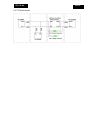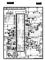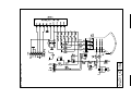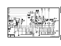
1
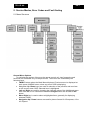
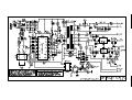
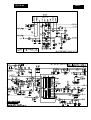
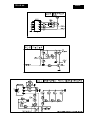
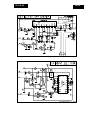
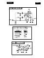
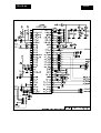
Colour Television
TE2.1E AA
Contents
1.
2.
3.
4.
5.
6.
7.
8.
9.
10.
11.
Page
Assembling/Disassembling Procedure
Technical Specifications, Connections and Chassis Overview
Safety Instructions, Warnings and Notes
Directions For Use
Mechanical Instructions
Service Modes Error Codes and Fault finding
Block Diagrams
Circuit Diagrams and PWB layouts
Alignments
Circuit Descriptions
Spare Part List
Revision list
2
3
4
5
6
7
12
15
29
38
40
44
© Copyright 2004 Philips Consumer Electronics B.V. Eindhoven, The Netherlands.
All rights reserved. No part of this publication may be reproduced, stored in a
retrieval system or transmitted, in any form or by any means, electronic, mechanical,
photocopying, or otherwise without the prior permission of Philips.
Published by JH 0467 Service PaCE
Subject to modification
EN 3122 785 14930
TE2.1E AA
EN 2
1. Technical Specifications, Connections and Chassis Overview
• Reception
100 programmes, PLL Tuning, Aerial Input : 75 Ohm
• TV Systems Off Air
PAL B/G + D/K + SECAM B/G + D/K, SECAM L/L’
• Add Systems Ext In
NTSC 3.58 + NTSC 4.43
• Sound Systems
B/G, D/K (FM A2+Nicam stereo), L/L’
• Screen Format
4:3
• Picture
16/9 Compress, 4:3, 4:3 Expand
• Sound
RMS Power Intern, 2 x 5W Stereo
• Teletext
10 page Top / Flof Text
• Connectors
Scart1: RGB + CVBS (rear Ext-1 )
Scart2: CVBS + SVHS (rear Ext-2 )
Headphone Front (3.5 mm)
Aerial Input (75 Ohm, rear)
• Mains Voltage
Official :220/240 VAC (± 10 %)
Real : 150/240 VAC (± 10 %)
Mains Frequency: 50 Hz (± 5 %)
• Languages OSD Menu
Turkish, English, French, German, Nederlands, Spanish, Italian.
• Power Consumption : 95W
• Stand-By Power Consumption : <8W
TE2.1E AA
EN 3
1.1
Connections
1.1.1
Rear Connections
EXT-2
EXT-1
EuroScart
1. Audio Output 1. right channel 0.5 VRMS/<1k0
2. Audio Input 1. right channel 0.5 VRMS/>10k0
3. Audio Output 2. left channel 0.5 VRMS/<1k0
4. GND (audio)
5. GND
6. Audio Input 2. left channel 0.5 VRMS/>10k0
7. RGB Input, blue (B)
8. Switch signal video (status)
9. GND
10. Reserved for clock signals (not connected)
11. RGB input, green (G)
12. Reserved for remote control
13. GND
14. GND switch signal RGB
15. RGB input, red (R) / Y
16. Switch Signal RGB
17. GND (video)
18. GND
19. Video Output 1Vpp/75 ohm
20. Video input 1Vpp/75 ohm / C
21. Shield
Ht1
20 18 16 14 12 10 8 6
4 2
21 19 17 15 13 11 9 7
5 3
1
TE2.1E AA
EN 4
2. Safety Instructions, Warnings and Notes
2.1 General
1. Use only the original spare parts with the same specifications for replacement.
2. Only the original fuse value should be used.
3. Safety components, indicated by the symbol,
should be replaced by components
identical to the original ones.
4. Main leads and connecting leads should be checked for external damage before
connection. Insulation must be checked. Parts contributing to the safety of the
product must not be damaged or obviously unsuitable. This is valid especially for
insulators and insulating parts.
5. Thermally loaded solder pads are to be sucked off and re-soldered.
6. Ensure that the ventilation slots are not obstructed.
7. Potentials as high as 25 KV are present when this receiver is operating. Operation
of the receiver outside the cabinet or with back cover removed involve a shock
hazard from the receiver.
8. Servicing should not be attempted by anyone who is not thoroughly familiar with
precautions necessary when working on high voltage equipment. Perfectly
discharge the high potential of the picture tube before handling it. The picture tube
is highly evacuated and if broken. Glass fragments will be violently expelled.
Always discharge the picture tube anode to the receiver chassis to keep of the
shock hazard before removing the anode cap.
9. Keep wire away from the high voltage or high temperature components.
10. When replacing a wattage resistor, keep the resistor 10mm away from the circuit
board.
2.2 Handling the MOS chip components
MOS circuit requires special attention with regard to static charges. Static charges may
occur with any highly insulated plastics and can be transferred to
persons wearing clothes and shoes made of synthetic materials. Protective circuits on the
inputs and outputs of MOS circuits give protection to a limited extend only due to time of
reaction. Please observe the following instructions to protect the components against
ESD.
1. Keep MOS components in conductive package until they are used. Most
components must never be stored in styropor materials or plastic magazines.
2. Personnel must not touch the MOS components to avoid electrostatic discharging.
3. Hold the component by the body touching the terminals.
4. Use only grounded instruments for testing and processing purposes.
5. Remove or connect MOS Ics when operating voltage is disconnected.
6. Personnel in charge must make sure that they are connected with the same
potential as the mass of the set by a wristband with resistance.
2.3 X-Ray radiation precaution
Excessive high voltage can produce potentially hazardous X-RAY radiation. To avoid
such hazard, the high voltage must not be above the specified limit. The nominal
value of the high voltage of this receiver is 25KV at zero beam current (minimum
brightness) under 220 V AC power source. The high voltage must not under any
circumstance, exceed 30KV. It is recommended the reading of the high voltage to be
recorded as a part of the service record. It is important to use an accurate and reliable
high voltage meter. The primary source of X-RAY radiation in the TV receiver is the
picture tube. For continued X-RAY radiation protection, the replacement tube must be
exactly the same type tube as specified in the part list.
TE2.1E AA
3. Directions for use
DFU can be found on the internet: www.p4c.philips.com
EN 5
TE2.1E AA
EN 6
4. Mechanical Intructions
Disassembly procedure is explained as below. Before disassembling the TV set please
read the safety instructions and warning parts of the service manual.
• Turn off TV and plug the mains out
• Remove screws (10 pieces) to dismount the back cover
• Disconnect the following sockets to take the chassis out ;
Deflection cables
Degaussing coil
Speaker cable
Power cable
• Remove the ground cable localised between tube module and mass wire.
• Remove the CRT drive module from picture tube.
• Remove anode cable localised on the picture tube.
• Slide out the chassis through the guides (no screws, straps or other fixing).
Please follow the assembly instructions explained below;
• Before inserting the chassis into guides, check the control buttons in front of the
chassis. In case of misplacement of control buttons place them into correct position.
• Slide the chassis into guides until the connection cables could be reached to their
sockets.
• Plug in the power cable socket to KP03.
• Plug in the degauss cable socket to KP02.
• Plug in the speaker cable socket to KA04.
• Place the CRT drive module on picture tube.
• Slide the chassis completely on its place. Be careful about control buttons.
• Plug in the deflection cable socket to KD02 and KD01.
• Place the anode cable to picture tube. Be careful about high voltage!
CRT drive module must be grounded via mass cable.
• Place the back cover back to its place.(10 screws)
• Plug the mains in.
• Turn on the TV.
TE2.1E AA
EN 7
5. Service Modes, Error Codes and Fault finding
5.1 Menu Structure
General Menu Options
To minimise the number of keys on the remote control unit, less frequently used
functions are accessible only via simple menus. The menus are controlled by the
following keys;
• “MENU” button makes the Main Menu displayed. Previous menu is displayed at
each press of MENU button, when any menu OSD is displaying.
• Navigation Up / Down keys are used for selection of the previous and next item
on the current menu OSD. Selected item is highlighted.
• Left and Right are used for changing the right side value of the highlighted menu
item if the item is not a submenu. Beside that Right button also is used as OK
button.
• Menu Right key is used to select a highlighted item, generally for displaying
submenu OSDs.
• Navigation Up / Down buttons are used for picture format 16:9 Compress, 4:3 or
4:3 Expand
TE2.1E AA
EN 8
5.2 Menu Control
Main Menu
Picture
Sound
Features
Installation
Picture Menu
Brightness
Colour
Contrast
Sharpness
Hue
Colour Temp
Store
⇒ 64 Steps
⇒ 64 Steps
⇒ 64 Steps
⇒ 64 Steps
⇒ 64 Steps (for NTSC only)
: Normal, Warm, Cool
Stored
Treble
Bass
Balance
AVL
Store
⇒ 64 Steps
⇒ 64 Steps
⇒ L-32 ..0.. 32-R
: On, Off
Stored
Sound Menu
Features Menu
Timer
Childlock
Parental Cont.
Ext-1
Ext-2
: On, Off
: VCR, Decoder/DVD
: VCR, Decoder/DVD
Timer Menu
Sleep
Time
Start Time
Program No
Activate
Parental Control Menu
Lock
Pr. Lock
: Off, 15, 30, 45,…, 120
⇒ XX : XX (am, pm)
⇒ XX : XX
: 0 … 99, SVHS2, Ext-2, Ext-1
: Off, Once, Daily
⇒ Off, XXX
⇒ Off, XXX
Installation Menu
Language
Country
Auto Store
Manual Store
Sort
Name
: English, French, German, Turkish, Dutch,
Italian, Spanish
: …, A, B, CH, D, DK, E, F, FI, GB, GR, I, N,
NL, P, IRL, L, S, TR
TE2.1E AA
EN 9
Auto Store Menu
Program No
TV
◊◊◊◊◊◊◊◊◊◊◊◊◊◊◊
Manual Store Menu
System
Europe
Search
Program No
Fine Tune
Store
⇒ Europe, France, West Europe, East
⇒ XXX.25 MHz
⇒ XX
⇒ -10 … +10 gauge
Stored
5.3 Country List
…, A (Austria), B (Belgium), CH (Switzerland), D (Germany), DK (Denmark), E (Spain), F
(France), FI (Finland), GB (UK), GR (Greece), I (Italy), N (Norway), NL (Netherlands), P
(Portugal), IRL (Ireland), L (Luxemburg), S (Sweden), TR (Turkey)
Philips 28” 4:3 FS
Austria
A
Belgium
B
Switzerland
CH
Germany
D
Denmark
DK
Spain
E
France
F
Finland
FI
United Kingdom
GB
Greece
GR
Italy
I
Norway
N
Netherlands
NL
Portugal
P
Ireland
IRL
Luxemburg
L
Sweden
S
Turkey
TR
Other
...
TE2.1E AA
EN 10
5.4 Fault finding diagram of Power supply
DP01 - 04
CP01 - 04
CP06, TP01
YES
Fuse
FP01
Defective
NO
RP07, RP05
open and
short circuit
NO
Voltage at
drain of
TP01
YES
RP06
YES
Voltage at
IP01 pin 11
< 1V
NO
RP11, DP07
YES
start-up
voltage
(6)
pin 14
< 8V
NO
TP01
YES
start-up voltage
varies ca. 8V
NO
IP01
Measure
VAP2, RP03, DP19
NO
+145V
adjustable with
VAP2
YES
Control range of
switched-mode
power supply
Switched mode Power
Supply defective, +145V
is missing or level is
wrong
TE2.1E AA
5.5 Chassis Diagram
EN 11
6.1 Block diagram
6. Block Diagrams
TE2.1E AA
EN 12
6.2 Supply Voltage Overview
TE2.1E AA
EN 13
TE2.1E AA
6.3 I2C BusOverview
EN 14
TE2.1E AA
EN 15
7. Circuit Diagrams and PWB layouts
Schematic overview
Components top
Components bottom
16
17
18
Schematics:
A01
A02
A03
A04
A05
A06
A07
A08
A09
A10
A11
A12
A13
A14
A15
A16
A17
19
20
21
22
23
23
24
24
25
25
25
26
26
27
27
28
27
TE2.1E AA
EN 16
TE2.1E AA
EN 17
TE2.1E AA
EN 18
TE2.1E AA
EN 19
TE2.1E AA
EN 20
TE2.1E AA
EN 21
TE2.1E AA
EN 22
TE2.1E AA
EN 23
TE2.1E AA
EN 24
TE2.1E AA
EN 25
TE2.1E AA
EN 26
TE2.1E AA
EN 27
TE2.1E AA
EN 28
TE2.1E AA
EN 29
8. Alignments
Note: SERVICE MODE IS ACTIVED BY PRESSING VOLUME – ON LOCAL
KEYBOARD AND TIMER BUTTON ON RC AT THE SAME TIME
This software provides menu flexibility and full control to software. Service persons can
adjust the TV in all manners. In service menu, you can see simply listed parameters,
software name, option bytes values, and bits. Initialisation of the software causes the
clear procedure of the error buffer and writing the software name to NVM. That means if a
NVM replacement occurs error buffer and software name will be achieved automatically.
In this software, program switching by menu added to service menu to create more user
friendly user interface. Beside that digit are used short cuts for the some specific positions
in service menu.
Start position : IF
1
2
3
4
5
6
7
8
9
: HP
: HP-EXP
: HS
: VSD
: WPR
: Ys
: OP2
: TSL
: INIT
This menu is being displayed whenever Service Menu is entered. The service engineer
can use this mode to check and to change option codes and other alignments for picture,
geometry, G2, and tuner adjustments. The overview of the menu is shown below:
8.1 TUNER ADJUSTMENT VARIABLES
*IF:
Intermediate frequency (58.8,45.8,38.9 or 38.00 MHz)
*IF1: Intermediate frequency, this bit is assigned to Secam L’ system. (33.4 or 33.9
MHz)
AGC : Automatic Gain Control
*TSL, TEL, TSM, TEM, TSH, THE, TBL, TBM, TBH:
These are all tuner depended
variables. This set supports various tuners and all of them have specific material
depended levels. Table for these settings are followed in default values section.
8.2 GEOMETRY ADJUSTMENT VARIABLES
HP, HB: These are all geometry adjustment variables based on horizontal changes of 4:3
mode. Horizontal Parallelogram, Horizontal Bow let us to make necessary
changes.
HP-EXP, HB-EXP: These are all geometry adjustment variables based on horizontal
changes of 4:3 EXPAND mode. Horizontal Parallelogram-EXP, Horizontal BowEXP, let us to make necessary changes.
HS: This is geometry adjustment variable based on horizontal changes.
Horizontal Shift let us to make necessary changes.
VA, VS, VSH:These are all geometry adjustment variables based on vertical changes.
Vertical Amplitude, Vertical Slope, Vertical Shift are vertical variables to adjust
vertical properties.
TE2.1E AA
EN 30
EXP-VA: This is geometry adjustment variable based on vertical changes of 4:3 EXPAND
mode amplitude.
EW, PW: These are all geometry adjustment variables based on horizontal changes of
4:3 mode. East-West, East-West Parabola Width are geometry variables to adjust
East-West properties.
EW-EXP, PW-EXP: These are all geometry adjustment variables based on horizontal
changes of 4:3 EXPAND mode. East-West EXPAND, East-West Parabola Width
EXPAND are geometry variables to adjust East-West properties of 4:3 EXPAND
mode.
UCP, LCP: These are geometry adjustment variables based on East-West upper&lower
corner parabola of 4:3 mode. Upper Corner Parabola, Lower Corner Parabola let
us to make necessary changes.
UCP-EXP, LCP-EXP: These are geometry adjustment variables based on East-West
upper&lower corner parabola of 4:3 EXPAND mode. Upper Corner Parabola
EXPAND, Lower Corner Parabola EXPAND let us to make necessary changes.
This is geometry adjustment variable based on East-West Trapezium changes of
4:3 mode.
TC-EXP: This is geometry adjustment variable based on East-West Trapezium changes
of 4:3 EXPAND mode.
VSD: Vertical scan disable off, this bit allows to make G2 adjustment. If service person
selects this item, information about G2 will be displayed and will guide you to
make adjustment by INCR, DECR, OK.
SC:
S-Correction
TC:
8.3 PICTURE ADJUSTMENT VARIABLES
BLR, BLG: Picture quality adjustment can be achieved by means of these variables.
These variables correspond to black level adjustment with red and green level.
(Black Level Red, Black Level Green)
WPR, WPG, WPB: These are also picture quality adjustment variables correspond to
white point correction with red, green and blue levels. (White Level Red, White
Level Green, White Level Blue)
Ys, Yn, Yp, Yo:
These are all Y-delay adjustment for various systems. (Y-delay
adjustment for SECAM, Y-delay adjustment for NTSC, Y-delay adjustment for
PAL, Y-delay adjustment for external sources). Colours interferences could be
prevented by these bits.
Connect a pattern to TV set and set pattern colour bar.
These bits could narrow junction line of colours.
8.4 OTHER ADJUSTMENT VARIABLES
CL:
TXT-CL:
H vol:
Cathode drive Level, picture quality could be improved by changing this
level. There could be paled colours by time. This properties help to revive.
Teletext Cathode drive Level, teletext mode and TV mode are completely
different from each other, so this adjustment should be repeated for
teletext mode.
Hotel Mode volume adjustment could be achieved. (Hotel Mode Volume)
8.5 OPTION BYTES
*ACL, FCO, SVO, HP2, FSL, OSO, FFI, BTSC, FMWS, BKS, IFS: These bits are control
bits of video processor explained in PDF file.
TE2.1E AA
EN 31
PAL-BG, PAL-DK, PAL-I, PAL-M, PAL-N, NTSC-M, NTSC-443, SECAM-BG, SECAMDK, FRANCE: These are all supported signals. By means of these setting display setting
can be adjusted according to country transmission systems.
SYS-FR:
Setting one of these bit enables the selection of the corresponding system.
SYS-UK:
Setting one of these bit enables the selection of the corresponding system.
*AV2, AV-S, AV3, AV3S:
Some external interfaces supported but beware of hardware
necessaries. It’s better the keep this bits default values
*Jr:
When set, stereo volume control via PWM-DAC's are enabled
HP:
Reserved, not used (in options)
*Vbar:
When set, a volume bar appears at the bottom of the screen when the
volume is changed and no menu or teletext is on.
SubWoof:
Reserved, not used
When set, 5 separate presets for sound and video are present. When
clear, only 1 preset for sound and video is available.
Lock:
Reserved, not used
Hotel:
To make the TV suitable in hotel/hospital use. In this mode some
restrictions are occurs in menus. So hotel subscriber or user cannot use
auto programme, volume restriction etc. (Hotel Mode)
16:9:
Tube format is hardware depended bit. If your tube format is 16:9 then this
bit should be set but this TV set designed in 4:3 tube.
*110:
This bit is also hardware depended bit. If your tube is 1100 then this bit
should be set but this TV set designed in 900 tubes.
*Hpol:
When set, the polarity of the horizontal sync for OSD is expected negative
going. When clear positive going.
*Vpol:
When set, the polarity of the vertical sync for OSD is expected negative
going. When clear positive going.
*Field:
When set, the vertical sync for OSD is in the second half line at the start of
an even field. When clear, Vsync is in the first half line.
*FEOut:
If this bit set FE signal (CVBS) available at ext even not switched to AV
source. Otherwise this signal available only after ext mode switching.
(internal CVBS signal)
Swon: When set, last switch off status is used for switching on.
*VGCheck: When set vertical guard fails and service mode is not active, the OSD is
not updated.
*Clock:
Enable/Disable Clock
*AM/PM:
Only valid in combination with option “Clock”. When set, the Clock is
defined as a 12-hour (AM/PM) clock, when clear a 24-hour clock is used.
*AVL:
When set, automatic volume levelling is enabled.
1norma:
Reserved, not used
*FLOF-TXT: Toggle between the flof teletext on/off. When set, the teletext flof is on.
*TR:
When set, sound cannot be muted in weak signals
UOC-J:
Reserved, not used
*IgnrSUP:
When set, ignore the status of SUP at power on, generally IC checks the
8V supply voltage.
*IgnrNDF:
When set, Ignore the status of NDF at power on, IC always controls the
vertical guard but this properties closes it at power on.
TXT on:
When set, teletext mode is available.
SYS-DK:
Setting one of these bit enables the selection of the corresponding system.
WSS:
When set, automatic picture mode switching is enabled according to
transmission.
*Presets:
*It is better to keep these bits at default values for this set.
TE2.1E AA
EN 32
Default values are as follow;
Init PHIST
IF
IFL1
HP
HB
EW
PW
UCP
LCP
TC
EXP-VA
HP-EXP
HB-EXP
EW-EXP
PW-EXP
UCP-EXP
LCP-EXP
TC-EXP
HS
VS
VA
SC
VSD
VSH
VX
BLR
BLG
WPR
WPG
WPB
Ys
Yn
Yp
Yo
AGC
CL
Bits 0
ACL
FCO
SVO
HP2
FSL
OSO
Bits1
FFI
BTSC
FMWS
BKS
IFS
TXT-CL
OP1
PAL-BG
PAL-DK
PAL-I
PAL-M
PAL-N
V4.19
38.9
33.9
31
31
49
21
13
13
31
40
32
31
49
39
1
1
35
28
42
15
31
Off
27
25
36
35
33
30
29
5
5
5
5
25
9
00
0
0
0
0
0
0
0
0
00
0
0
0
0
0
0
0
0
5
83
1
1
0
0
0
OP2
SECAM-DK
FRANCE
SYS-FR
SYS-UK
AV2
SVHS2
AV3
AV3S
OP3
PAL L
Jr
HP
Vbar
SubWoof
Presets
Lock
Hotel
OP4
16:9
110
Hpol
Vpol
Field
FEOut
Swon
VGCheck
OP5
Clock
AM/PM
AVL
1norma
FLOF-TXT
TR
MSP-CLIP
OP6
UOC-J
ignrSUP
ignrNDF
TXT on
East/West
WSS
TSL
TEL
TSM
TEM
TSH
TEH
TBL
TBM
TBH
H vol
35
1
0
1
0
1
1
0
0
69
1
0
0
1
0
1
1
0
F2
0
1
0
0
1
1
1
1
A5
1
0
1
0
0
1
0
1
10
0
0
0
0
1
0
0
0
45
118
118
400
400
890
03
06
85
63
0
TE2.1E AA
EN 33
NTSC-M
NTSC-443
SECAM-BG
0
0
1
P.S.: Blank option bits should be zero.
8.6 OPTION BYTES (ADJUSTED FOR 70TB4417/XX)
0
1
2
3
4
5
6
7
OP
P
P
P
P
P
N
N
S
1
A
A
A
A
A
T
T
E
0
1
2
3
4
5
6
7
OP
S
F
S
S
A
S
A
A
2
E
R
Y
Y
V
V
V
V
0
1
2
3
4
5
6
7
OP 3
PAL
J R
HP
VB a r
SUbw
PR e s
LOc k
HTM
6 9
L
F 2
0
1
2
3
4
5
6
7
OP 4
1 6 :
1 1 0
Hp o
V p o
F i e
F EO
Swo
VGC
L
L
L
L
L
S
S
C
C 3
- BG
- DK
- I
- M
- N
C - M
C - 4 4 3
AM - BG
3 5
AM - DK
NCE
- FR
- UK
C
A
S
S
2
HS 2
3
3 S
oo f
e t s
9
l
l
l d
u t
n
h e c k
1
1
0
0
0
0
1
1
1
0
1
0
1
1
0
0
1
0
0
1
0
1
1
0
0
1
0
0
1
1
1
1
TE2.1E AA
0
1
2
3
4
5
6
7
0
1
2
3
4
5
6
7
OP 5
A 5
C l o c k
AM - PM
AVL
1 n o r mA
F LOF - T X T
TR
MS P - C L I P
EN 34
1
0
1
0
0
1
0
1
OP 6
1 0
UOC - J
I g n r SUP
I g n r NDF
0
0
0
0
T XT oN
1
E A S T / WE S T 0
0
WS S
0
8.7 ADJUSTMENTS
You will need following equipments to carry out the adjustment procedures;
a- PLL Pattern generator for Secam L'
b- PLL Pattern generator PAL BG
c- Patern generator for white pattern
d- Color Analyzer (CA100)
8.7.1. GEOMETRY ADJUSTMENT
a.
b.
c.
d.
e.
f.
g.
h.
i.
j.
k.
HP, HP-EXP
HB, HB-EXP
HS
VA, EXP-VA
VS
VSH
EW, EW-EXP
PW, PW-EXP
UCP,UCP-EXP
LCP, LCP-EXP
TC, TC-EXP
Geometry alignments help us to change the geometry of displayed picture. Position of
picture could also be redefined by using those alignments.
HP: Horizontal Parallelogram 4:3
HP-EXP: Horizontal Parallelogram 4:3 EXPAND
HB: Horizontal Bow 4:3
HB-EXP: Horizontal Bow 4:3 EXPAND
HS: Horizontal Shift
VA: Vertical amplitude 4:3
TE2.1E AA
EN 35
EXP-VA: Vertical amplitude 4:3 EXPAND
VS: Vertical slope
VSH: Vertical shift
EW: East West width for picture setting 4:3
EW-EXP: East West width for picture setting 4:3 EXPAND
PW: East West parabola for picture setting 4:3
PW-EXP: East West parabola for picture setting 4:3 EXPAND
UCP: East West corner parabola upper for picture setting 4:3
UCP-EXP: East West corner parabola upper for picture setting 4:3 EXPAND
LCP: East West corner parabola lower for picture setting 4:3
LCP-EXP: East West corner parabola lower for picture setting 4:3 EXPAND
TC: Trapezium 4:3
TC-EXP: Trapezium 4:3 EXPAND
Set pattern generator to crosshatch pattern
Connect a pattern generator to TV, detect the transmission
Enter service menu and adjust the geometry settings; HP, HB, HS, VA, VS, VSH,
EW, PW, UCP, LCP, TC, HP-EXP, HB-EXP, EXP-VA, EW-EXP, PW-EXP, UCPEXP, LCP-EXP, TC-EXP
Press menu button to leave service menu
8.7.2 G2 ADJUST ADJUSTMENT
Enter the service menu and activate VSD selection
Turn the G2 potentiometer on FBT until you get OK sign on CRT
Directions will guide the service engineer as DECR, INCR
8.7.3. VIDEO (PICTURE) ADJUSTMENT
1
2
3
4
5
BLR
BLG
WPR
WPG
WPB
Video items are used for getting better quality picture in the sense of color.
BLR: Black Level Red
BLG: Black Level Green
WPR: White Level Red
WPG: White Level Green
WPB: White Level Blue
Ys, Yn, Yp, Yo: These are all Y-delay adjustment for various systems. (Y-delay
adjustment for SECAM, Y-delay adjustment for NTSC, Y-delay adjustment for
PAL, Y-delay adjustment for external sources). Colours interferences could be
prevented by means of these bits. These bits could narrow junction line of colours
Connect a pattern to TV set and set pattern colour bar, white pattern at 100 IRE,
black pattern (Dark gray pattern at 10 IRE), sequentially.
Contrast 70%, brightness middle, color saturation middle
Video parameters, BLR, BLG, WPR, WPG, WPB, Ys, Yn, Yp, Yo, could be
adjusted in this condition
CL: Cathode drive Level, picture quality could be improved by changing this level. There
could be paled colours by time. This properties help to solve problem.
TXT-CL: Teletext Cathode drive Level, teletext mode and TV mode are completely
different from each other, so this adjustment should be repeated for teletext mode.
TE2.1E AA
EN 36
Remark:
It may be necessary after low light alignment to check and to re-align the
high light and to repeat several times the procedure to obtain good alignment for both low
and high light.
8.8 TUNER / IF ALIGNMENT
1. IF
2. IF1
3. TSL
4. TEL
5. TSM
6. TEM
7. TSH
8. THE
9. TBL
10. TBM
11. TBH
In the case of tuning problem, tuning properties could be adjustable.
IF:
Intermediate frequency (58.8,45.8,38.9 or 38.00 MHz)
IF1: Intermediate frequency, this bit is assigned to Secam L’ system. (33.4 or 33.9
MHz)
AGC : Automatic Gain Control
TSL, TEL, TSM, TEM, TSH, THE, TBL, TBM, TBH:
These are all tuner depended
variables. This set supports various tuners and all of them have specific material
depended levels. Table for these settings are followed in default values section.
(Start frequency of the low-band, end frequency of the low-band, start frequency of the
mid-band, end frequency of the mid-band, start frequency of the high-band, end
frequency of the high-band, hex value for switching to the low-band, hex value for
switching to the mid-band, hex value for switching to the high-band)
TSL
TEL
TSM
TEM
TSH
TEH
TBL
TBM
TBH
Tuner Parameter in Service Menu
Start Frequency of the low-band in MHz
End Frequency of the low-band in MHz
Start Frequency of the mid-band in MHz
End Frequency of the mid-band in MHz
Start Frequency of the high-band in MHz
End Frequency of the high-band in MHz
hex Value needed for switching to the low-band
hex Value needed for switching to the mid-band
hex Value needed for switching to the high-band
PHILIPS
45
160
160
440
440
890
A1
92
34
OREGA
45
118
118
400
400
890
3
6
85
SAMSUNG
45
150
150
427
427
890
1
2
0C
8.9 HTM
Installation and Child Lock Menus are omitted in HTM. You can not search any
channel when the HTM is activated.
Volume level cannot be increased higher then certain level in HTM. The volume
limiting level is a pre-defined value in service menu.
ALPS
45
180
180
465
465
890
1
2
0C
TE2.1E AA
EN 37
8.10 SYSTEM VOLTAGE ADJUSTMENT
•
Switch the TV in AV mode by pressing AV button on remote control unit. (Minimum
beam current condition)
•
Adjust the VAP2 potentiometer until 145Vdc measured on cathode pin of DP08 diode.
•
Please check the other test points and required voltages.
TE2.1E AA
EN 38
9. Circuit Descriptions
9.1 Descriptions
No descriptions avaialble
9.2 ABBREVIATIONS
+BIN
+VMEM
AGC
AMOUT
AV.SW
AV.VID
B/G-SND
BCL
BCUR
BIN
BLKIN
BLUE
CHROMA
CNTRL(LED+KEY)
CVBSEXT1
CVBSEXT2
CVBSINT
E.AUD
E/W
E/WDRIVE
EX.AUD
FBLIN
FOCUS
GIN
GND
GREEN
H_DRIVE
H_FLYBACK
HEATER
HTR
IDRIVEIDRIVE+
IF1
IF1_S
IF2
IF2_S
KEYB
LED
MUTE
OUT_L
OUT_R
QSSO
RED
RESET
RIN
RMOT
SC1IL
System voltage
Eeprom voltage
Auto Gain Control
AM sound output
External Video Switch
Switched Video signal from AV
BG Sound
Beam Current Limiter
Beam Current
Blue in
Black Current Input
Blue component of picture
Chroma input
Control signal of IR and keyboard
External Composite Video Signal 1
External Composite Video Signal 2
Internal CVBS signal
ExternalAudio
East West
East West Drive
External audio
Fast blanking in
Focus adjustment
Green in
Ground
Green component of picture
Horizontal Drive
Horizontal Flayback
Heater of the tube
Heater of the tube
Vertical drive Vertical drive +
Intermediate Frequency 1
Intermediate frequency 1
Intermediate Frequency 2
Intermediate frequency 2
Front panel keyboard
IR signal
Mute signal
Headphone sound signal left
Headphone sound signal right
QSS Output
Red component of picture
Reset signal
Red in
Remote Control
Scart1 sound input left
TE2.1E AA
SC1IR
SC1OUTL
SC1OUTR
SC2IL
SC2IR
SC2OUTL
SC2OUTR
SCL
SCL1
SCREEN
SDA
SDA1
SPK_L
SPK_R
ST_BY
STAT_AV1
STAT_AV2
SW1
TV_S/L
TV_S/R
TV_VID
VGUARD
EN 39
Scart1 sound input right
Scartout Left
Scartout Right
Scart2 sound input left
Scart2 sound input right
Scart2 output left
Scart2 output right
Clock bus
Clock bus 1
FBT screen adjustment
Data bus
Data bus 1
Speaker left
Speaker right
Standby
Pin 8 status of scart 1
Pin 8 status of scart 2
IF Switch for L/L’
TV sound left
TV sound right
TV video
Vertical guard voltage
TE2.1E AA
10.
Spare Parts List
Main panel
Various
F302
FV06
FV07
HD01
PTC1
S003
SC01
SC02
SC03
SC04
SW01
TU01
X301
XV01
0020 272 32250
0020 411 00130
0020 411 00200
0023 443 50241
0025 215 17190
0025 285 54011
0050 510 84620
0050 510 84631
0360 160 10071
0674 200 01811
0707 224 16591
0751 102 11050
4822 130 41275
6080 000 02291
6085 800 03660
6103 081 70021
6310 200 92101
0377 300 07771
4822 242 10254
0377 300 07801
0750 164 20221
0347 103 03651
0750 208 00031
0811 011 14031
0811 011 14031
0811 011 14031
0811 011 14031
0810 000 00141
6168 000 20001
0490 300 00541
0490 300 00091
Cable 300mm h
CABLE 4P*1SKT HOP.COLOURED 50X
CABLE 4P*1SK HOP. PRINTED 60X7
CABLE VERTICAL.COLOUREDI PHL35
CABLE HOLDERLI 6PX2SKT 42CM
Mains cord 220cm
Insulating plate 13x23mm
Bead
Ferrite ring 31x7x19
FUSE 3.15A 250V TIME-LAG SFTY
A66EHJ13X01 FST VCOLOR
FUSE HOLDER BLUE 3.15AMP.SFTY
BY228
COIL CHOKE 38MH 1.2A PFC
COIL DEG.28'CPT 18R SFTY
SPEAKER 16R 5W 126X58MMPHILIPS
R/C RCLE013A STR TXT PHILPS
SAW K9453M
TPWA02B-TF21
Filter SAW K3953M
Socket headphone
THERM PTC 18R 30% 3P 10MM SFTY
CRT socket Narrow neck
Tact switch h
Tact switch h
Tact switch h
Tact switch h
Mains switch
Tuner CTT5020E/CTF5510
Xtal 18.432MHz HC49U
Xtal 12.000 MHz
0020 205 11270
0400 401 71021
0400 405 00271
6200 030 51041
0424 408 61061
0424 468 62251
0400 461 51021
0400 461 51021
0400 400 26861
0400 670 41081
0424 465 01061
0400 670 41861
4822 051 30008
5322 126 11578
5322 126 11578
4822 051 30008
0400 670 41081
0400 670 41081
0424 465 01061
0424 165 02261
0424 165 02261
0424 465 01061
0424 465 01061
0400 520 43381
0400 520 43381
0400 520 43381
0420 339 01011
0400 430 45661
0424 465 01061
0400 670 41081
0400 520 43381
0400 670 41081
0424 465 01061
0400 670 41081
0400 520 43381
0400 520 43381
0400 520 43381
0400 430 45661
0400 430 45661
0400 320 42281
0400 320 42281
5322 126 11578
4822 051 30008
4822 051 30008
0424 165 02261
0424 165 02261
5322 126 11578
2020 552 96684
2020 552 96684
0424 402 51081
CABLE DOUBLETERM.SYH 9CM KLT.
1nF 10% 2kV
CAP CER 2.7NF 500V 10% B
CAP MKT 100NF 250VDC 10% 15MM
10oF 20% 250V
2.2oF 20% 250V
1nF 10% 1kV
1nF 10% 1kV
CAP CER 6.8NF 2KV 10% B
100nF 20% 50V 0805
10oF 20% 50V
CAP CER 680NF 16V 20% 0603
Jumper 0603
1nF 10% 50V 0603
1nF 10% 50V 0603
Jumper 0603
100nF 20% 50V 0805
100nF 20% 50V 0805
10oF 20% 50V
22oF 20% 50V
22oF 20% 50V
10oF 20% 50V
10oF 20% 50V
330nF 20-80% 50V 0805
330nF 20-80% 50V 0805
330nF 20-80% 50V 0805
3.3oF 20% 50V
56pF 5% 50V 0603
10oF 20% 50V
100nF 20% 50V 0805
330nF 20-80% 50V 0805
100nF 20% 50V 0805
10oF 20% 50V
100nF 20% 50V 0805
330nF 20-80% 50V 0805
330nF 20-80% 50V 0805
330nF 20-80% 50V 0805
56pF 5% 50V 0603
56pF 5% 50V 0603
2.2pF 5% 50V 0805
2.2pF 5% 50V 0805
1nF 10% 50V 0603
Jumper 0603
Jumper 0603
22oF 20% 50V
22oF 20% 50V
1nF 10% 50V 0603
470nF 10% 25V 0805
470nF 10% 25V 0805
1000oF 20% 25V
3
C--F
C001
C002
C003
C004
C005
C006
C007
C008
C317
C318
C321
C324
C325
C326
C329
C330
C331
C332
C333
C334
C338
C339
C340
C341
C342
C343
C344
C345
C346
C347
C348
C349
C350
C351
C352
C353
C354
C355
C356
C357
C359
C360
C361
C362
C363
C372
CA01
CA02
CA04
EN 40
CA05
CA06
CA07
CA08
CA10
CA11
CA12
CA13
CA14
CA15
CA16
CA17
CC70
CD01
CD02
CD03
CD06
CD08
CD11
CD13
CD14
CD15
CD16
CD17
CD18
CD19
CD20
CD21
CD22
CD23
CD24
CD25
CD26
CD28
CD29
CD30
CD31
CD32
CD51
CD52
CD53
CD54
CD56
CD57
CD58
CD59
CD61
CD64
CD65
CE01
CE02
CE03
CE04
CE05
CE07
CE08
CE11
CE15
CE16
CE18
CE19
CE20
CE21
CE22
CE24
CE26
CH01
CH02
CH03
CH04
CH05
CH06
CP01
CP02
CP03
CP04
CP05
CP06
CP08
CP09
CP10
CP11
CP12
CP13
CP14
CP15
CP16
CP18
CP19
0424 402 51081
0400 400 42261
0400 400 42261
0424 463 51071
0400 670 41081
0400 670 41081
4822 126 14238
4822 126 14238
0424 485 04761
0424 485 04761
0424 485 04761
0424 485 04761
0424 142 54761
9965 000 20812
6210 030 03331
5322 121 42661
0424 408 61061
6200 030 46801
6200 130 81041
0424 492 54771
0400 670 41081
6210 040 04731
0424 465 01061
6210 040 04731
0400 401 71021
0424 165 02261
6193 238 71031
6200 130 54741
6200 031 02731
0424 171 62271
0424 492 54771
0400 670 41081
0400 402 53311
0424 166 32261
0424 685 14791
0421 401 61071
6200 040 01051
0400 401 56811
0400 520 44881
6200 130 81041
0400 520 44881
0424 166 32261
6180 130 12231
0424 492 54771
0424 141 64761
4822 126 13883
0400 670 41081
6200 130 81041
5322 126 11583
0424 465 01061
5322 126 11578
5322 126 11578
5322 126 11578
5322 126 11578
5322 126 11578
5322 126 11578
0424 465 01061
5322 122 33861
5322 122 33861
0400 402 53361
0400 402 53361
4822 126 14238
4822 126 14238
0400 402 53361
0400 402 53361
5322 122 33861
0424 463 51071
0424 463 51071
4822 126 13193
4822 126 13193
4822 126 13193
4822 126 13193
6200 040 62241
6200 040 62241
0400 401 52211
0400 401 52211
6200 041 33331
0427 199 01071
6200 031 46811
0424 165 02261
5322 126 11583
0407 320 41081
0400 520 44861
4822 126 14238
0402 587 64721
5322 126 11583
0424 406 31181
9965 000 20812
0424 406 31181
1000oF 20% 25V
22nF 20% 50V 0603
22nF 20% 50V 0603
CAP ELECT 100MF 35V 20%
100nF 20% 50V 0805
100nF 20% 50V 0805
2.2nF 50V 0603
2.2nF 50V 0603
47oF 20% 50V
47oF 20% 50V
47oF 20% 50V
47oF 20% 50V
47oF 20% 25V
47oF 20% 250V
CAP KT 33NF 100V 5% 5MM
330nF 5% 63V
10oF 20% 250V
CAP MKP 680NF 400V 5%15-22.5MM
100nF 5% 63V
470oF 20% 25V
100nF 20% 50V 0805
47nF 100V
10oF 20% 50V
47nF 100V
1nF 10% 2kV
22oF 20% 50V
CAP MKP 10NF 1.6KV 3.5%15-25MM
470nF 5% 250V
CAP MKP 27NF 1KV 5% 15-27.5MM
Capacitor
470oF 20% 25V
100nF 20% 50V 0805
330pF 250V
22oF 63V
6.8oF 250V
100oF 20% 16V
10nF 50V
680pF 10% 1kV
CAP CER 470PF 50V 5% COG 0805
100nF 5% 63V
CAP CER 470PF 50V 5% COG 0805
22oF 63V
22nF 50V
470oF 20% 25V
CAP ELECT 47MF 16V 20%
220pF 5% 50V
100nF 20% 50V 0805
100nF 5% 63V
10nF 10% 50V 0603
10oF 20% 50V
1nF 10% 50V 0603
1nF 10% 50V 0603
1nF 10% 50V 0603
1nF 10% 50V 0603
1nF 10% 50V 0603
1nF 10% 50V 0603
10oF 20% 50V
120pF 10% 50V
120pF 10% 50V
330pF 10% 50V 0603
330pF 10% 50V 0603
2.2nF 50V 0603
2.2nF 50V 0603
330pF 10% 50V 0603
330pF 10% 50V 0603
120pF 10% 50V
CAP ELECT 100MF 35V 20%
CAP ELECT 100MF 35V 20%
4.7nF 10% 63V
4.7nF 10% 63V
4.7nF 10% 63V
4.7nF 10% 63V
220nF 20% 275V
220nF 20% 275V
2.2nF 10% 1kV
2.2nF 10% 1kV
33nF 5% 630V
100oF 20% 400V
680pF 10% 2kV
22oF 20% 50V
10nF 10% 50V 0603
100pF 5% 50V 0805
470pF 5% 50V 0603
2.2nF 50V 0603
4.7nF 20% 400V
10nF 10% 50V 0603
CAP ELECT 1000MF 50V 20%
47oF 20% 250V
CAP ELECT 1000MF 50V 20%
TE2.1E AA
CP20
CP21
CP22
CP25
CP26
CP28
CP29
CP30
CP31
CP32
CP33
CP34
CP35
CP36
CP37
CP40
CP41
CP42
CP43
CP44
CP45
CP52
CP53
CT05
CT06
CT07
CT08
CT09
CT14
CT17
CV01
CV03
CV04
CV06
CV07
CV08
CV10
CV11
CV12
CV13
CV14
CV15
CV16
CV17
CV18
CV19
CV20
CV21
CV22
CV23
CV26
CV27
CV28
CV29
CV30
CV31
CV33
CV34
CV35
CV36
CV37
CV38
CV39
CV40
CV41
CV42
CV43
CV44
CV45
CV47
CV48
CV49
CV50
CV51
CV54
CV55
CV56
CV58
CV61
CV62
CV63
CV64
CV65
CV66
CV67
0400 401 72231
0424 492 54771
0400 670 41081
0400 670 41081
0424 165 02261
0424 492 54771
0400 670 41081
0400 401 72231
0424 142 54761
0400 670 41081
0424 408 61061
0424 142 54761
0400 670 41081
0400 501 51011
6200 050 76831
4822 051 30334
4822 126 13193
0407 320 41081
5322 126 11583
0424 402 51081
4822 126 13883
0400 401 52211
0400 401 52211
0407 320 41081
0407 320 41081
0424 142 51071
0400 670 41081
0424 465 01061
0424 465 01061
0400 670 41081
0424 465 01061
0400 670 41081
0424 465 01061
0424 465 01061
0400 670 41081
4822 126 11785
0400 670 41081
6210 040 04731
0424 465 02251
0400 670 41081
6210 030 04731
6210 030 04731
0421 401 61071
0400 670 41081
0421 401 61071
6200 040 72241
6200 040 72241
0400 420 44861
0400 420 44861
0400 420 44861
5322 126 11583
0421 401 61071
6200 130 81041
5322 126 11578
2020 552 93683
2020 552 93683
4822 126 13193
0424 165 01051
4822 126 14238
0424 465 01061
0400 430 45661
0400 430 45661
0400 670 41081
0400 670 41081
0421 401 61071
0421 401 61071
0407 320 41081
0407 320 41081
2020 552 96684
4822 126 13883
9965 000 12523
6200 030 52231
5322 126 11578
0400 310 46861
0424 142 54761
0400 520 44861
0421 401 61071
0424 465 02251
4822 126 14238
0424 142 54761
0400 310 42261
5322 126 11583
9965 000 12523
4822 126 14238
4822 126 14238
CAP CER 220PF 1KV 10% BN
470oF 20% 25V
100nF 20% 50V 0805
100nF 20% 50V 0805
22oF 20% 50V
470oF 20% 25V
100nF 20% 50V 0805
CAP CER 220PF 1KV 10% BN
47oF 20% 25V
100nF 20% 50V 0805
10oF 20% 250V
47oF 20% 25V
100nF 20% 50V 0805
100pF 1kV
68nF 20% 275V
330kY 5% 0.062W
4.7nF 10% 63V
100pF 5% 50V 0805
10nF 10% 50V 0603
1000oF 20% 25V
220pF 5% 50V
2.2nF 10% 1kV
2.2nF 10% 1kV
100pF 5% 50V 0805
100pF 5% 50V 0805
100oF 20% 25V
100nF 20% 50V 0805
10oF 20% 50V
10oF 20% 50V
100nF 20% 50V 0805
10oF 20% 50V
100nF 20% 50V 0805
10oF 20% 50V
10oF 20% 50V
100nF 20% 50V 0805
47pF 5% 50V 0603
100nF 20% 50V 0805
47nF 100V
2.2oF 20% 50V
100nF 20% 50V 0805
47nF 5% 50V
47nF 5% 50V
100oF 20% 16V
100nF 20% 50V 0805
100oF 20% 16V
220nF 10% 63V
220nF 10% 63V
47nF 10% 50V 0603
47nF 10% 50V 0603
47nF 10% 50V 0603
10nF 10% 50V 0603
100oF 20% 16V
100nF 5% 63V
1nF 10% 50V 0603
1.2nF 10% 50V 0603
1.2nF 10% 50V 0603
4.7nF 10% 63V
1oF 20% 50V
2.2nF 50V 0603
10oF 20% 50V
56pF 5% 50V 0603
56pF 5% 50V 0603
100nF 20% 50V 0805
100nF 20% 50V 0805
100oF 20% 16V
100oF 20% 16V
100pF 5% 50V 0805
100pF 5% 50V 0805
470nF 10% 25V 0805
220pF 5% 50V
0.22oF 20% 50V
CAP MKP 2.2MF 250V 5% 27.5MM
1nF 10% 50V 0603
CAP CER 68PF 50V 5% COG 0603
47oF 20% 25V
470pF 5% 50V 0603
100oF 20% 16V
2.2oF 20% 50V
2.2nF 50V 0603
47oF 20% 25V
22pF 5% 50V 0603
10nF 10% 50V 0603
0.22oF 20% 50V
2.2nF 50V 0603
2.2nF 50V 0603
9051 022 80620
0301 056 47811
0300 507 15221
0300 507 10221
0300 507 10221
COLOURED CABIN.28' PT 4365 (10
0.47Y 5% 1W
1.5kY 1/2W
RES. C. COMP 1K 1/2W 10%
RES. C. COMP 1K 1/2W 10%
2
4KBN
R001
R002
R003
R004
EN 41
R005
R007
R008
R009
R010
R012
R013
R014
R323
R324
R327
R330
R331
R332
R337
R345
R346
R351
R352
R353
R354
RA04
RA05
RA06
RA07
RA08
RA09
RA10
RA11
RA12
RA13
RA14
RA15
RA16
RA17
RC25
RC26
RC30
RC42
RC46
RC47
RC52
RC58
RC59
RC60
RC71
RC72
RC73
RC74
RC75
RC76
RC77
RC79
RC90
RC91
RD01
RD02
RD03
RD04
RD05
RD06
RD07
RD09
RD10
RD11
RD12
RD13
RD14
RD15
RD16
RD17
RD18
RD19
RD20
RD21
RD50
RD51
RD52
RD53
RD54
RD55
RD56
RD57
RD58
RD59
RD61
RD62
RD63
RD64
RE01
RE02
RE03
RE04
RE05
0300 507 10221
0300 507 15221
0300 206 10131
0300 206 10131
0300 206 10131
0300 206 33411
0300 206 22511
0300 206 33411
4822 051 30101
0300 206 22911
4822 051 30008
4822 051 30101
4822 117 12925
4822 051 30101
0300 206 10911
4822 051 30222
4822 051 30222
4822 051 30103
4822 051 30103
4822 051 30682
4822 051 30683
4822 051 30472
4822 051 30102
2322 702 81828
2322 702 81828
4822 051 30223
4822 051 30102
4822 051 30123
0300 106 83061
4822 051 30102
4822 051 30123
0300 106 83061
4822 051 30008
4822 051 30563
0301 406 39211
4822 051 30479
4822 051 30223
4822 051 30101
4822 051 30332
4822 051 30332
4822 051 30101
0300 106 15161
4822 051 30183
4822 051 30103
4822 051 30123
0300 106 15161
0300 106 27261
4822 051 30561
4822 051 30391
0300 106 82161
4822 051 30102
0300 106 12261
4822 051 30561
4822 117 13632
4822 117 12902
4822 051 30273
0300 206 22131
0300 106 82061
4822 117 13632
0300 256 15001
0300 106 47361
0300 506 39311
0300 206 15431
0300 206 15431
0301 056 10911
0301 006 22901
0300 557 22811
0300 206 47331
4822 051 30102
0300 206 47911
0300 206 47231
0300 106 56221
0302 087 47811
0300 506 10211
0300 106 15161
0300 206 10131
0300 206 10131
4822 051 30332
0300 557 22811
0301 086 10911
0301 086 22010
0301 006 39101
0300 596 22211
0300 206 22011
4822 051 30333
4822 051 30008
0300 106 22461
4822 051 30221
0300 206 75011
4822 051 30101
4822 051 30101
4822 051 30109
4822 051 30759
4822 051 30102
RES. C. COMP 1K 1/2W 10%
1.5kY 1/2W
100Y 5% 1/4W
100Y 5% 1/4W
100Y 5% 1/4W
330kY 5% 1/4W
2.2MY 5% 1/4W
330kY 5% 1/4W
100Y 5% 0.062W
2.2Y 5% 1/4W
Jumper 0603
100Y 5% 0.062W
47kY 1% 0.063W 0603
100Y 5% 0.062W
1Y 5% 1/4W
2.2kY 5% 0.062W
2.2kY 5% 0.062W
10kY 5% 0.062W
10kY 5% 0.062W
6.8Y 5% 0.062W
68kY 5% 0.062W
4.7Y 5% 0.062W
1kY 5% 0.062W
8.2Y 5% 0.1W 0603
8.2Y 5% 0.1W 0603
22kY 5% 0.062W
1kY 5% 0.062W
12kY 5% 0.1W
2kY 5% 1/10W 0603
1kY 5% 0.062W
12kY 5% 0.1W
2kY 5% 1/10W 0603
Jumper 0603
56kY 5% 0.062W
RESISTOR C.F 3.9K 1/6W 5%
47Y 5% 0.062W
22kY 5% 0.062W
100Y 5% 0.062W
3.3Y 5% 0.062W
3.3Y 5% 0.062W
100Y 5% 0.062W
150Y 5% 1/10W 0603
18kY 5% 0.062W
10kY 5% 0.062W
12kY 5% 0.1W
150Y 5% 1/10W 0603
RESISTOR C.F 2.7K 1/10W5% 0603
560Y 5% 0.062W
390Y 5% 0.062W
820Y 5% 1/10W 0603
1kY 5% 0.062W
1.2kY 5% 0603
560Y 5% 0.062W
100kY 1% 0603 0.62W
8.2kY 1% 0.063W 0603
27kY 5% 0.062W
220Y 5% 1/4W
RESISTOR C.F 82R 1/10W5% 0603
100kY 1% 0603 0.62W
15Y 1/4W fusable
RESISTOR C.F 4.7K 1/2W 5%
39Y 1/4W
150kY 5% 1/4W
150kY 5% 1/4W
1Y 5% 1W fusable
2.2Y 5% 1W fuseable
0.22Y 5% 1/2W fusable
RESISTOR C.F 47K 1/4W 5%
1kY 5% 0.062W
4.7Y 1/4W
4.7k 5% 1/4W
5.6kY 5% 1W fusable
RESISTOR M.O. 0.47R 2W %5
1kY 5% 1/2W
150Y 5% 1/10W 0603
100Y 5% 1/4W
100Y 5% 1/4W
3.3Y 5% 0.062W
0.22Y 5% 1/2W fusable
RESISTOR M.O 1R 1W 5%
RESISTOR M.O 22R 1W 5%
RESISTOR FUSIBLE 39R 1/4W 5%
220Y 1W
22Y 1/4W
33kY 5% 0.062W
Jumper 0603
RESISTOR C.F 220K 1/10W5% 0603
220Y 5% 0.062W
RESISTOR C.F 75R 1/4W 5%
100Y 5% 0.062W
100Y 5% 0.062W
10Y 5% 0.062W
75Y 5% 0.062W
1kY 5% 0.062W
TE2.1E AA
RE06
RE07
RE08
RE09
RE10
RE11
RE12
RE13
RE14
RE16
RE17
RE24
RE25
RE26
RE27
RE30
RE31
RE32
RE33
RE35
RE36
RF01
RF02
RF03
RF05
RH01
RH02
RP01
RP02
RP03
RP04
RP05
RP06
RP07
RP08
RP09
RP10
RP11
RP15
RP16
RP17
RP18
RP21
RP22
RP24
RP25
RP26
RP27
RP28
RP29
RP30
RP31
RT07
RT08
RT09
RT14
RT15
RT17
RT18
RV01
RV02
RV03
RV04
RV05
RV06
RV08
RV09
RV10
RV11
RV12
RV13
RV14
RV15
RV16
RV17
RV21
RV22
RV23
RV24
RV25
RV26
RV27
RV28
RV29
RV30
RV32
RV33
RV34
RV35
RV36
RV37
RV38
RV41
RV42
4822 051 30101
4822 051 30759
4822 051 30759
4822 051 30759
4822 051 30101
5322 117 13042
4822 051 30103
4822 051 30101
4822 051 30123
4822 051 30759
4822 051 30123
4822 051 30759
4822 051 30123
4822 051 30123
4822 051 30759
4822 051 30109
4822 051 30102
4822 051 30759
4822 051 30101
5322 117 13042
4822 051 30103
0300 557 22811
0300 557 22811
0300 557 22811
0300 557 22811
0300 596 22211
0300 596 22211
0751 002 11220
4822 117 12925
5322 117 13042
0300 206 10331
0300 106 11231
0300 106 39231
0300 206 56030
4822 051 30333
0300 506 47611
0320 406 33521
0300 256 15001
0302 086 15321
4822 051 30008
4822 051 30103
4822 051 30103
4822 051 30472
4822 051 30102
0320 576 22951
0300 106 11461
4822 051 30102
4822 117 13632
0300 006 27261
0301 081 50311
4822 117 12925
0320 576 22951
5322 117 13042
4822 051 30153
4822 051 30123
0300 206 10131
0300 206 10131
4822 051 30008
4822 051 30223
4822 051 30332
4822 051 30391
0300 106 12161
4822 051 30101
4822 051 30101
0300 106 18161
0300 206 10131
0300 106 12261
0300 206 10031
4822 051 30101
0300 106 18161
4822 051 30103
4822 051 30101
4822 051 30101
4822 051 30101
4822 051 30103
4822 051 30681
4822 051 30393
4822 051 30563
4822 051 30101
4822 051 30273
0300 106 75461
4822 051 30153
4822 051 30101
4822 051 30479
0300 206 47131
4822 051 30332
0300 106 12261
0300 106 12261
0300 106 12261
4822 117 13632
4822 051 30102
0301 006 22901
4822 051 30759
4822 051 30472
100Y 5% 0.062W
75Y 5% 0.062W
75Y 5% 0.062W
75Y 5% 0.062W
100Y 5% 0.062W
3.9kY 1% 0.063W 0603
10kY 5% 0.062W
100Y 5% 0.062W
12kY 5% 0.1W
75Y 5% 0.062W
12kY 5% 0.1W
75Y 5% 0.062W
12kY 5% 0.1W
12kY 5% 0.1W
75Y 5% 0.062W
10Y 5% 0.062W
1kY 5% 0.062W
75Y 5% 0.062W
100Y 5% 0.062W
3.9kY 1% 0.063W 0603
10kY 5% 0.062W
0.22Y 5% 1/2W fusable
0.22Y 5% 1/2W fusable
0.22Y 5% 1/2W fusable
0.22Y 5% 1/2W fusable
220Y 1W
220Y 1W
CONN 2P VRT PFC(RED)7.5MM
47kY 1% 0.063W 0603
3.9kY 1% 0.063W 0603
10kY 5% 1/4W
1MY 2% 1/4W
3.9MY 2% 1/4W
RESISTOR C.F 56R 1/4W %5
33kY 5% 0.062W
4.7MY 5% 1/2W
33kY 5W
15Y 1/4W fusable
15k 5% 2W
Jumper 0603
10kY 5% 0.062W
10kY 5% 0.062W
4.7Y 5% 0.062W
1kY 5% 0.062W
RESISTOR W.W2.2R 5W10%VRTSFTY
RESISTOR C.F 1K 1/10W1% 0603
1kY 5% 0.062W
100kY 1% 0603 0.62W
2k7 1% 1/10W 0603
RESISTOR M.F 150K 1/4W 1%
47kY 1% 0.063W 0603
RESISTOR W.W2.2R 5W10%VRTSFTY
3.9kY 1% 0.063W 0603
15kY 5% 0.062W
12kY 5% 0.1W
100Y 5% 1/4W
100Y 5% 1/4W
Jumper 0603
22kY 5% 0.062W
3.3Y 5% 0.062W
390Y 5% 0.062W
RESISTOR C.F 120R 1/10W5% 0603
100Y 5% 0.062W
100Y 5% 0.062W
RESISTOR C.F 180R 1/10W5% 0603
100Y 5% 1/4W
1.2kY 5% 0603
10Y 1/4W
100Y 5% 0.062W
RESISTOR C.F 180R 1/10W5% 0603
10kY 5% 0.062W
100Y 5% 0.062W
100Y 5% 0.062W
100Y 5% 0.062W
10kY 5% 0.062W
680Y 5% 0.062W
39kY 5% 0.062W
56kY 5% 0.062W
100Y 5% 0.062W
27kY 5% 0.062W
750kY 5% 1/10W 0603
15kY 5% 0.062W
100Y 5% 0.062W
47Y 5% 0.062W
470Y 5% 1/4W
3.3Y 5% 0.062W
1.2kY 5% 0603
1.2kY 5% 0603
1.2kY 5% 0603
100kY 1% 0603 0.62W
1kY 5% 0.062W
2.2Y 5% 1W fuseable
75Y 5% 0.062W
4.7Y 5% 0.062W
EN 42
RV47
RV48
RV49
RV50
RV51
RV53
RV54
RV55
RV56
RV57
RV58
RV59
RV60
RV62
RV66
RV68
RV69
RV70
RV71
RV72
RV73
RV74
RV75
RV78
RV79
RV80
RV81
RV82
RV84
VAP2
0300 106 15161
4822 051 30101
4822 051 30101
4822 051 30153
0300 106 12261
4822 051 30101
4822 051 30101
4822 051 30101
0300 206 10031
0300 106 12261
0300 206 10131
0300 106 12261
4822 051 30103
0300 106 15161
4822 051 30472
4822 051 30472
4822 051 30472
4822 051 30759
4822 051 30472
4822 051 30103
4822 117 12925
4822 051 30101
0300 106 12261
4822 051 30101
0300 106 12261
4822 117 12903
4822 051 30334
4822 051 30759
4822 117 12902
6113 800 12031
150Y 5% 1/10W 0603
100Y 5% 0.062W
100Y 5% 0.062W
15kY 5% 0.062W
1.2kY 5% 0603
100Y 5% 0.062W
100Y 5% 0.062W
100Y 5% 0.062W
10Y 1/4W
1.2kY 5% 0603
100Y 5% 1/4W
1.2kY 5% 0603
10kY 5% 0.062W
150Y 5% 1/10W 0603
4.7Y 5% 0.062W
4.7Y 5% 0.062W
4.7Y 5% 0.062W
75Y 5% 0.062W
4.7Y 5% 0.062W
10kY 5% 0.062W
47kY 1% 0.063W 0603
100Y 5% 0.062W
1.2kY 5% 0603
100Y 5% 0.062W
1.2kY 5% 0603
1.8kY 1% 0.063W 0603
330kY 5% 0.062W
75Y 5% 0.062W
8.2kY 1% 0.063W 0603
Potmeter 20k 0.1W 30%
8411 190 10390
6083 800 02361
6080 800 00751
6080 800 00751
6080 000 00071
6089 800 04011
6083 800 00381
6087 800 02411
6080 800 00191
6080 800 00191
6080 800 00331
6080 800 00331
6080 800 00191
6080 800 00191
6080 800 00191
6080 800 00191
6087 800 02411
0360 702 04111
0360 702 04111
6089 800 02060
6080 000 00021
6080 000 00021
6083 800 02361
6087 800 02411
6080 000 00301
6087 800 02411
6080 800 00751
6089 800 00111
6080 000 00021
6080 000 00021
6080 000 00021
6080 000 00021
6080 000 00021
6080 000 00021
6089 800 00121
6080 800 00201
0360 702 04111
9965 000 20799
0468 480 00001
0468 480 00001
0468 480 00001
0468 480 00001
4822 130 40959
4822 130 41691
4822 130 41691
4822 130 40959
4822 130 41691
4822 130 41053
4822 130 61265
4822 130 63127
4822 130 40959
4822 130 40855
4822 130 41691
4822 130 40959
4822 130 40959
0460 000 01211
0469 862 94161
4822 130 40959
0020 205 11160
4822 130 41691
COMP. LED WITH HOLDER PHILIPS
Coil choke 150oH
22oH
22oH
COIL 3.3UH 5% 0.21A AXIAL FIX
COIL LINEARITY LC110&AT4042/92
COIL INJECT. 4.7MH 0.3A DC
Ferrite bead 3.5*9*0.8
8.2oH 5%
8.2oH 5%
COIL 33UH 0.16A 5% AX.FIXED
COIL 33UH 0.16A 5% AX.FIXED
8.2oH 5%
8.2oH 5%
8.2oH 5%
8.2oH 5%
Ferrite bead 3.5*9*0.8
FERRIT BEAD LI0805H151R-00 SMD
FERRIT BEAD LI0805H151R-00 SMD
LINE FILTER 2*9MH 2.5A SFTY
10oH 5%
10oH 5%
Coil choke 150oH
Ferrite bead 3.5*9*0.8
Coil choke 900Y 50MHz
Ferrite bead 3.5*9*0.8
22oH
1oH 5%
10oH 5%
10oH 5%
10oH 5%
10oH 5%
10oH 5%
10oH 5%
4.7oH 5%
COIL 1MH 10% 100HZ
FERRIT BEAD LI0805H151R-00 SMD
Filter 4.43 MHz
BC848B
BC848B
BC848B
BC848B
BC547B
BC556B
BC556B
BC547B
BC556B
BC639
BU508AF
BU2525AF
BC547B
BC337
BC556B
BC547B
BC547B
TRS.BUZ334 / SPP11N60C2
2SA720 / BC327
BC547B
Cable 30mm Bk
BC556B
.
5LED
L002
L301
L302
L306
LD02
LD03
LD04
LE01
LE02
LE03
LE04
LE05
LE06
LE07
LE08
LE09
LE10
LE11
LFP1
LH01
LH02
LP02
LP03
LP04
LP05
LT01
LT02
LV01
LV02
LV03
LV04
LV05
LV06
LV07
LV08
LV10
T301
T302
T303
TA01
TA02
TC10
TC11
TC14
TC70
TC90
TD01
TD02
TD02
TD03
TD04
TD50
TE01
TE04
TP01
TP03
TP05
TRQ*
TV01
TE2.1E AA
TV04
TV05
TV06
TV10
TV11
TV12
TV13
TV14
4822 130 40959
4822 130 40959
0460 009 99101
4822 130 40959
4822 130 40959
4822 130 40959
4822 130 40959
0468 480 00001
BC547B
BC547B
TRS.BD680
BC547B
BC547B
BC547B
BC547B
BC848B
4822 130 30842
4822 130 30842
4822 130 30842
0483 214 23201
4822 130 30842
4822 130 30842
4822 130 30842
0483 221 07001
0483 221 07001
4822 130 30621
4822 130 83338
4822 130 83351
0487 738 09001
4822 130 42606
4822 130 30621
4822 130 42606
4822 130 42606
4822 130 42606
0480 000 00021
4822 130 30621
0480 000 00021
4822 130 30621
4822 130 42606
4822 130 31983
4822 130 34382
4822 130 30621
4822 130 42606
4822 130 30621
4822 130 30621
4822 130 30621
9051 081 42410
0483 214 23201
0483 214 23201
0483 214 23201
0483 214 23201
0480 000 00021
4822 130 30621
0483 265 28011
4822 130 30959
4822 130 31983
0480 000 00021
0483 270 28001
0480 000 00021
4822 209 81397
4822 130 83338
0483 270 30001
4822 130 31983
4822 130 83338
BAV21
BAV21
BAV21
1N4007
BAV21
BAV21
BAV21
BA282&BA482
BA282&BA482
1N4148
LL4148
BZX55-B2V4
KLR114L
BYD33J
1N4148
BYD33J
BYD33J
BYD33J
BYV95C
1N4148
BYV95C
1N4148
BYD33J
BAT85
BZX79-B8V2
1N4148
BYD33J
1N4148
1N4148
1N4148
COLOURED.BUTTON QUARTET 28'PT4
1N4007
1N4007
1N4007
1N4007
BYV95C
1N4148
DIODE RECT.BYT56K SOD-64
ZTK33B
BAT85
BYV95C
DIODE RECT.BYW76 SOD-64
BYV95C
TL431CLPST
LL4148
DIODE ZNR.36V BZD23C SOD-81
BAT85
LL4148
8411 600 28290
9322 147 25682
6093 300 01251
0020 205 11220
9051 102 80410
0020 205 11230
9352 713 37112
0450 000 01561
4822 209 32269
0450 000 02211
0451 900 00021
4822 209 15576
0450 383 62811
0452 381 03081
0450 000 09871
6087 800 02411
6087 800 02411
6087 800 02411
6087 800 02411
6087 800 02411
6087 800 02411
6087 800 02411
6087 800 02411
6087 800 02411
4822 051 30008
4822 051 30008
4822 051 30008
4822 051 30008
4822 051 30008
4822 051 30008
COMP..PFC ELIM 1.2A 28'PHILIPS
M24C16-WBN6
IR receiver TSOP2236
Cable 180mm Bk
BACK COVER 28'PT 4365 GREY (10
CABLE DOUBLETERM.SYH.40CMCEN-K
TDA6107JF/N3
MSP3410G
TDA2616/N1
IC TDA8351 VERTICAL DEFLECTION
TDA16846
LE33CZ
TCDT1101
LM7805
IC TDA9365-PQ1 PSNTSC110DEG10P
Ferrite bead 3.5*9*0.8
Ferrite bead 3.5*9*0.8
Ferrite bead 3.5*9*0.8
Ferrite bead 3.5*9*0.8
Ferrite bead 3.5*9*0.8
Ferrite bead 3.5*9*0.8
Ferrite bead 3.5*9*0.8
Ferrite bead 3.5*9*0.8
Ferrite bead 3.5*9*0.8
Jumper 0603
Jumper 0603
Jumper 0603
Jumper 0603
Jumper 0603
Jumper 0603
0
D001
D002
D003
D004
D005
D006
D007
D307
D308
DA01
DA03
DC03
DC10
DD01
DD02
DD03
DD04
DD06
DD08
DD09
DD10
DD11
DD12
DD13
DD14
DD15
DD16
DD50
DE01
DE02
DORT
DP01
DP02
DP03
DP04
DP06
DP07
DP08
DP09
DP10
DP11
DP12
DP13
DP19
DT01
DV01
DV03
DV04
/1
7PFC
IC02
IC04
A--M
ARKP
GND*
I001
I302
IA01
ID50
IP01
IP02
IP03
IP04
IV01
J002
J009
J010
J065
J083
J092
J097
J109
J110
J132
J138
J146
J164
J180
J202
EN 43
J203
J208
J219
JC01
JC03
JC05
JS03
JS04
JS05
JS06
JS07
KA04
KB**
KC03
KD01
KD02
KD03
KE01
KP02
KP03
KPF1
KPF1
KV01
NTC1
O--N
ONOF
WD01
WD02
WP02
4822 051 30008
4822 051 30008
6087 800 02411
4822 051 30008
4822 051 30008
4822 051 30008
4822 051 30008
4822 051 30008
4822 051 30008
4822 051 30008
4822 051 30008
0751 004 11000
0020 211 00450
0751 007 11031
0751 002 01010
0750 302 11001
0020 920 00450
0750 402 10081
0751 002 11781
0750 302 61010
0020 992 22740
0751 002 11220
8411 400 10016
0300 208 51031
0020 205 11240
9051 020 00250
6023 000 33071
6042 000 00551
6021 900 00031
Jumper 0603
Jumper 0603
Ferrite bead 3.5*9*0.8
Jumper 0603
Jumper 0603
Jumper 0603
Jumper 0603
Jumper 0603
Jumper 0603
Jumper 0603
Jumper 0603
Connector 4p v
CABLE DOUBLE TERMIN. DLK+KLT22
7P flat
4p h m
2p v 5mm
Cable 4p/450/3p Wh
SOCKET SCART DOUBLE PT92 PHLP.
2p 7.5mm
2p v 10mm
CABLE 2PX2SKT DBL.ISLT PFC25CM
CONN 2P VRT PFC(RED)7.5MM
COMP.CABLE HOLD. 6PX2SKT 42CM
NTC 5Y
CABLE DOUBLETERM.SYH.25CM KLT
BYL.BUTTON ONOFF 28PT4365 1081
Transf. hor. drive
TRF.FBT 110°PT92 SFTY
TRF.SMPS 110°PT92 90-270VACSFT
TE2.1E AA
11.
Revision list
First release
EN 44