1
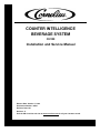
COUNTER INTELLIGENCE
BEVERAGE SYSTEM
CI8100
Installation and Service Manual
Release Date: October 7, 2004
Publication Number: 84247
Revision Date: NA
Revision: V
Visit the IMI Cornelius web site at www.cornelius.com for all your Literature needs.
INSTALLATION AND SERVICE MANUAL
The products, technical information, and instructions contained in this manual are subject
to change without notice. These instructions are not intended to cover all details or variations of the equipment, nor to provide for every possible contingency in the installation,
operation or maintenance of this equipment. This manual assumes that the person(s)
working on the equipment have been trained and are skilled in working with electrical,
plumbing, pneumatic, and mechanical equipment. It is assumed that appropriate safety
precautions are taken and that all local safety and construction requirements are being
met, in addition to the information contained in this manual.
To inquire about current revisions of this and other documentation or for assistance with
any Cornelius product contact:
www.cornelius.com
800-238-3600
Trademarks and copyrights:
Aurora, Cornelius, Decade, Hydro Boost, Sitco, Spirit, UF-1, Vanguard, Venture, Olympus, and Vista are registered trademarks of IMI Cornelius Inc.
Optifill trademark is pending.
This document contains proprietary information and it may not be
reproduced in any way without permission from Cornelius.
Printed in U.S.A.
Copyright © 2004, All Rights Reserved, IMI Cornelius, Inc.
TABLE OF CONTENTS
General Description . . . . . . . . . . . . . . . . . . . . . . . . . . . . . . . . . . . . . . . . . . . . . . . . .
Specifications . . . . . . . . . . . . . . . . . . . . . . . . . . . . . . . . . . . . . . . . . . . . . . . . . . . . . .
Unpacking and Inspection . . . . . . . . . . . . . . . . . . . . . . . . . . . . . . . . . . . . . . . . . . . . .
Installation Requirement . . . . . . . . . . . . . . . . . . . . . . . . . . . . . . . . . . . . . . . . . . . . . .
1
1
1
1
Installation Instructions . . . . . . . . . . . . . . . . . . . . . . . . . . . . . . . . . . . . . . . . . . . . . . . . 3
Dispenser Module Assembly . . . . . . . . . . . . . . . . . . . . . . . . . . . . . . . . . . . . . . . . . . . 3
CI8100 Exploded View . . . . . . . . . . . . . . . . . . . . . . . . . . . . . . . . . . . . . . . . . . . . . . . . . 5
Parts List CI8100 . . . . . . . . . . . . . . . . . . . . . . . . . . . . . . . . . . . . . . . . . . . . . . . . . . . 6
CI8100 Module Assembly . . . . . . . . . . . . . . . . . . . . . . . . . . . . . . . . . . . . . . . . . . . . . . .
General Description . . . . . . . . . . . . . . . . . . . . . . . . . . . . . . . . . . . . . . . . . . . . . . . . . .
Installation Requirements. . . . . . . . . . . . . . . . . . . . . . . . . . . . . . . . . . . . . . . . . . . . . .
Installation . . . . . . . . . . . . . . . . . . . . . . . . . . . . . . . . . . . . . . . . . . . . . . . . . . . . . . . . .
Operation . . . . . . . . . . . . . . . . . . . . . . . . . . . . . . . . . . . . . . . . . . . . . . . . . . . . . . . . .
Changing Lamps . . . . . . . . . . . . . . . . . . . . . . . . . . . . . . . . . . . . . . . . . . . . . . . . . . . .
Changing the Graphics . . . . . . . . . . . . . . . . . . . . . . . . . . . . . . . . . . . . . . . . . . . . . . .
7
8
8
8
8
8
8
MER40 Exploded View I. . . . . . . . . . . . . . . . . . . . . . . . . . . . . . . . . . . . . . . . . . . . . . . . . 9
Parts List MER40 . . . . . . . . . . . . . . . . . . . . . . . . . . . . . . . . . . . . . . . . . . . . . . . . . . 10
MER40 Exploded View II . . . . . . . . . . . . . . . . . . . . . . . . . . . . . . . . . . . . . . . . . . . . . . . 11
Installation and Service Manual
IMPORTANT: To the user - This manual is a guide for installing, operating and maintaining this
equipment. Please read and maintain this document for service and troubleshooting.
G ENERAL D ESCRIPTION
The CI8100 consists of three sub-modules (OMEGA mechanically refrigerated dispenser, M15 ice
dispenser and MER40 merchandiser) in an integrated package.
SPECIFICATIONS
See individual manuals for specifications.
UNPACKING
AND INSPECTION
The units, packed individually, were thoroughly inspected before leaving the factory. Any damage should
be noted at the time of delivery (no later than 15 days from date of delivery) and immediately reported to
the carrier. File the claim with the delivering carrier.
INSTALLATION REQUIREMENT
COUNTER
A flat surface able to support 700 pounds. Counter cut outs
for product lines, drainage line and electrical cords. See
template provided with installation kit for dimensions and
locations.
Clearance above the CI8100 must be a minimum of 18” to
allow removal of the upper cabinet for servicing the power
deck, filling the ice bin as well as providing adequate
ventilation. There should be a minimum of 4 inches
clearance on each side and rear of the unit. FAILURE TO
COMPLY MAY RESTRICT AIR MOVEMENT
SUFFICIENTLY TO IMPAIR REFRIGERATION
PERFORMANCE.
SEAL
A silastic caulk, approved for use in a food zone (Dow
Corning 732 or equivalent) is required to seal equipment to
the counter top.
ELECTRICAL
Use separate 120VAC 20 amp 60HZ grounded duplex
outlets to accommodate each module and/or accessories.
The outlets should be located below the counter and within
three (3) feet of the unit and installed according to national
and local electrical codes.
DRAIN
An approved three (3) inch or larger drain must be located
within three (3) feet of the dispenser. The preferred drain is
an open floor sink with a center cone. Do not use copper for
soft drink drains.
WATER
Water pipe connections and fixtures directly connected to a
potable water supply shall be sized, installed and maintained
according to federal, state, and local laws. A minimum of 3/
8”ID tubing is required to dispenser.
An optional carbonator is required.
Noncarbonated drinks require a minimum incoming water
pressure of 55 psi and a maximum of 75 psi. An optional
booster pump is required if pressure is not maintained at or
above 55 psi. If above 75 psi, install a water regulator.
Use water filters to eliminate undesirable elements in the
water, such as chlorine in excess of 1.5 ppm. Use a type
that does not remove all chlorine.
© 2004, IMI Cornelius Inc.
-1-
Publication Number: 84247
Installation and Service Manual
CO2 SYSTEM
The CO2 tank must be located next to a solid wall and
chained.
The CO2 storage area must be open and vented.
On bulk CO2 tanks ensure vaporizing and regulator capacity
is sufficient (i.e., 8-9 scfm average per dispenser and
carbonator.
Set CO2 regulators as appropriate:
- Room temp. carbonators - 105 psi for all valves with
minimum flow rate of 1.5 oz/sec.
- Cold carbonator - 90psi
If CO2 is to be located under the counter, 30 inches under
counter clearance is required.
SYRUP SYSTEM
Allow no more than two (2) Fast Flow Valves per Bag-In-Box
(BIB) pump or Figal.
Up to 4 BIB’s can be connected together, whether a selector
(automatic switch-over device) is used or not, as long as all
bags are at the same level, not above or below each other.
Because of pressure drop within figal fittings, no more than
two (2) Figals should be connected in series.
Publication Number: 84247
-2-
© 2004, IMI Cornelius Inc.
Installation and Service Manual
INSTALLATION INSTRUCTIONS
The installation process described below should be performed in the sequence as presented:
DISPENSER MODULE ASSEMBLY
1.
2.
3.
4.
5.
6.
7.
8.
Remove packaging and crating material from each module. Save the packing material in case
items need to be returned. Remove protective covering as each part is assembled.
Using the template, provided with the installation kit, mark the counter to indicate the location of the
modules.
Cut the access holes and slots as indicated.
Apply a generous bead of silastic to the counter top in all areas where the riser (mounting base) will
contact the counter.
Set the OMEGA beverage dispenser, in its proper position (note which side ice dispenser is
mounted), making sure the cabinet is set on the riser.
Set the M15 ice dispenser on the riser. Gently slide it to the rear. The three (3) inch wide slot in the
bottom of the ice dispenser should align with the corresponding hole in the counter top.
Place side panels on each side of the beverage system. For systems with a front channel attached
with three screws on each side, align them so that the keyholes face toward the rear of the unit.
Install the rear straps by inserting them into the keyholes in the side panels (the flange on the rear
straps should be against the ice dispenser). Push down on the straps locking them into place.
Next, align the dispensers by lining them up so that the rear straps are flush against the back of the
dispenser.
For systems with a front channel that attaches to the side panels by locking into the keyholes in the
return flange of the side panels, be sure the front panels with the keyholes in the return flange are
positioned at the front of the system.
For systems without keyholes in the return flange, install the front channel assembly by attaching it
to each side panel using three hex head screws. (It is recommended that a socket wrench be used
to tighten the hex head screws.) Apply a bead of silastic to all areas where the drip pan support will
contact the counter. Place the drip pan support on the counter, aligning its mounting holes to those
in the side panels. Attach the drain pan support to the front of the side panels using hex head
screws through the back of the support. At this point, the Counter Intelligence Beverage System
should be properly aligned. If necessary, reposition the components slightly to ensure any gaps are
less than 1/32 inches wide.
For systems with keyholes in the return flange: With the hinge halves above the top plate, install
the front channel by inserting the rivets into the keyholes of each side panel simultaneously and
push down, locking it into place. Use one (1) hex head screw on each side to secure the front
channel in place.
WARNING: Hex head screws must be installed to prevent the front channel from disengaging
from the keyholes during servicing of the beverage system of its merchandiser.
9.
10.
11.
Complete sealing all the modules to the counter top by wiping the excess silastic off the counter
and leave a smooth joint between the counter and modules.
Connect the drain hoses to the drain pan and install drain pan on the support frame. All counter
cutouts for drain and electrical lines must be sealed with an acceptable material in accordance with
local and state health and building codes.
The MER40 is a lighted sign and is shipped partially assembled (See Section IV):
A. Remove two screws from top cover on MER40.
B. Remove top cover and plastic lens, diffuser, and graphics panel.
C. Remove fluorescent lamps packed inside MER40.
D. Install the MER40 merchandiser by mating the slip hinges at the top of the merchandiser and
dispensers.
E. Rotate the MER40 upward and rest it on the two support brackets.
© 2004, IMI Cornelius Inc.
-3-
Publication Number: 84247
Installation and Service Manual
F. Plug the MER40 cord into the outlet located on the top front panel of the OMEGA, then close
supports to allow the MER40 to hang in its vertical position.
G. Install fluorescent lamps into lamp holders.
H. Clean lens and diffusers, being careful not to scratch. Carefully insert graphics panel between
diffuser and lens and slide into slots along front edge of the merchandiser body.
I. Replace MER40 top cover and two screws. Merchandiser is illuminated when dispenser is
plugged in and power switch is turned on.
12. Connect all product lines, carbonated water lines, potable water lines and drain lines as marked.
13. Activate the ice dispenser lever to assure proper placement of the ice dispenser front cover. Install
the splash plate and cup rests.
The installation is now complete. The system should be sanitized in accordance with the cleaning
and sanitizing procedures found in the Installation and Service Manuals for the modules. See
individual manuals for start-up and operation.
Publication Number: 84247
-4-
© 2004, IMI Cornelius Inc.
Installation and Service Manual
CI8100 EXPLODED VIEW
© 2004, IMI Cornelius Inc.
-5-
Publication Number: 84247
Installation and Service Manual
PARTS LIST CI8100
Item No.
1
Description
84202
Rear Strap Assembly, Sabre Grey
84202-001
Rear Strap Assembly, Stainless
2
84242-002
Upper Cabinet
*
84244
Top Plate
3
84200-001
Side Panel, Left, Sabre Grey
84200-201
Side Panel, Left, Stainless
84200-002
Side Panel, Right, Sabre Grey
84200-202
Side Panel, Left, Stainless
84239-001
Front Channel
5A*
84241
Splash Plate
6
84220
Bracket, Upper Cabinet
7
84213
Drip Pan
8
84211-001
(was 84211)
Drip Skirt
9
84214
Cup Rest, Beverage
10
84113
Cup Rest, Ice
11
84000-655
Riser
12
24844-003
Access Panels
14
82991-101
Valve Mounting Plate
15
83475-100
Liner Assembly, Foamed
16
84000-200
Ice Dispenser, Lever (Not Shown)
*
84000-206
Ice Dispenser, M15C, Push Button
*
84000-565
MER40 Merchandiser
*
84000-559
MER40 Merchandiser
*
60093-100
Fuse for MER40
4
5
Publication Number: 84247
Part No.
-6-
© 2004, IMI Cornelius Inc.
Installation and Service Manual
CI8100 MODULE ASSEMBLY
© 2004, IMI Cornelius Inc.
-7-
Publication Number: 84247
Installation and Service Manual
IMPORTANT: To the user - This manual is a guide for installing, operating and maintaining this
equipment. Please read and maintain this document for service and troubleshooting.
GENERAL DESCRIPTION
The MER40 merchandiser is an internally lit graphics display illuminated by two 42 watt (F30T12CWHO)
fluorescent lamps.
INSTALLATION R EQUIREMENTS
Location
The MER40 is designed to be mounted on a vertical surface. The supporting structure
must be able to support 30 pounds. The MER40 is approximately 34-7/8 inches long by
13-3/16 inches high by 5 inches deep.
Electrical
Use a 120VAC 20 amp 60HZ grounded outlet.
INSTALLATION
The top back corners of the MER40 contain two slip pin hinge half brackets which are used to hang the
sign. The sign may be attached so that the sign may be rotated about the hinge brackets.
1.
2.
3.
4.
5.
6.
Fasten the two hinge halves to the mating hinge brackets on the supporting surface. The half
which has the spring-loaded pin must be mounted on the right side. The fasteners used to mount
the hinge brackets must be able to support a minimum of 40 pounds.
Pull the spring-loaded pin to the right and insert the left side of the merchandiser onto the left hinge
half.
Align the right hinge on the MER40 with the spring hinge on the supporting surface.
Release the spring pin to engage the hinge.
Move the merchandiser form side to side to make sure the pins are engaged.
Fluorescent tubes have been carefully packed inside the MER40 and have to be installed. Refer to
Changing Lamps.
OPERATION
Plug power cord into a 120VAC 60HZ grounded outlet.
CHANGING LAMPS
1.
2.
3.
4.
5.
6.
7.
Unplug the MER40 from power source.
Remove the MER40 from its supporting surface and remove two screws and top cover.
Carefully slide the plastic lens and graphics panels up and out.
Remove the old lamp by rotating it 90 degrees and lift out of the socket.
Install the new lamp by rotating it 90 degrees to the locked position.
Carefully replace the lens and graphics panels, making sure that the clear plastic panel is on the
outside.
Replace the cover and two screws.
CHANGING THE G RAPHICS
1.
2.
3.
4.
5.
Unplug the MER40 from power source.
Remove the MER40 from its supporting surface and remove two screws and top cover.
Spread the lens panels slightly and lift the graphics panel out the top.
Insert the new graphics panel.
Replace the top cover and two screws.
Publication Number: 84247
-8-
© 2004, IMI Cornelius Inc.
Installation and Service Manual
MER40 EXPLODED VIEW I
© 2004, IMI Cornelius Inc.
-9-
Publication Number: 84247
Installation and Service Manual
PARTS LIST MER40
Item No.
Part No.
Description
1
84232-200
Body
2
84141-006
Lamp Holder Assembly
3
60098-001
Lamp Socket
4
84232-003
Cover, Wireway
5
60097-001
Ballast
6
84235-001
Clear Panel Lens
7
Consult Factory
Graphic Panel
8
84235-002
Diffuser Panel Lens, White
9
84234-202
Top Assembly
10
84223-002
Hinge, Right
10a
84223-004
Hinge, Left
11
60195-031 (Before 11-14-96)
82051-001 (After 11-14-96)
Cord Set
12
60040-078
Strain Relief
Publication Number: 84247
- 10 -
© 2004, IMI Cornelius Inc.
Installation and Service Manual
MER40 EXPLODED VIEW II
© 2004, IMI Cornelius Inc.
- 11 -
Publication Number: 84247
Installation and Service Manual
Publication Number: 84247
- 12 -
© 2004, IMI Cornelius Inc.
IMI Cornelius Inc.
www.cornelius.com