1
RA 29 586/06.98
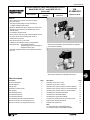
Electro-Hydraulic 4-Way Directional Servo Valve
Model 4 WS 2 E.10… and 4 WSE 2 E. 10…
(Series 4X)
... 4600 PSI
(315 bar)
... 20 GPM
(75 L/min)
Replaces: 05.94
K 4242-5
Size 10 (D 05)
RA
29 586/06.98
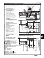
Features:
– Servo valve for the closed loop control of position,
force and velocity
– Two stage modular design for easy maintenance
– 1st stage is a flapper/nozzle design
– Mounts on standard ISO 4401-5, NFPA T3.5.1 M R1 and
ANSI B 93.7 D 05 interface, with additional X1 port for
external piloting
– For subplates, see RA 45 054
– Can be used in conjunction with several feedback devices
– Dry torque motor which is isolated and cannot be
contaminated by the fluid
– May also be used as a 3-way valve
– 5 different coils available to meet your requirements
– Valve with integrated electronics are adjusted and tested
as a unit
Model 4 WS 2 EM 10 -4X/..B...
with mechanical feedback, associated electronic amplifier
card (ordered separately)
K 4246-3
– Valve electronics • are available separately
(standard plug-in Euro card design) or
• integrated into the valve
Model 4 WSE 2 EE 10 -4X/..B...
with electronic feedback and integrated electronics
Table of contents
Description
Page
Description
Page
Functional description
2
Operating curves–flow vs. load
Sectional diagram
3
Operating curves–flow vs. signal
10
10
Ordering code
4
Operating curves–frequency response, barometric feedback
10
Explanation of ordering code
5
Operating curves–frequency response, mechanical feedback
11
Valve symbols
5
Operating curves–frequency response, electrical feedback
12
Technical data–general
6
Unit dimensions–mechanical feedback
13
Technical data–hydraulic
6
Unit dimensions–electrical feedback
14
Technical data–electrical
7
Unit dimensions–barometric feedback
14
Technical data–inductive positional transducer
7
Unit dimensions, sandwich plate for external pilot oil drain
15
Electrical connections for external electronics
8
Flushing plate, flushing instructions
15
Electrical connections for integrated electronics
9
External control electronics
16
Note:
For service manual, request RDE 29 586-S
For complete parts list, request RDE 29 586-E!
1/16
RA 29 586/06.98
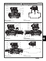
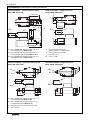
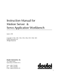
Functional description
Valves Model 4 WS 2 E.10... and 4 WSE 2E.10... are electronically
operated 2-stage servo valves. These valves are primarily used for
closed loop control of position, force and velocity.
Mechanical feedback on the 2nd stage (Fig.1.1 and 1.2)
The control spool in the second stage (9) is physically connected
to the torque motor (1) with the mechanical feedback linkage (5).
These valves consist of two stages, the 1st stage (2), has a
magnetic torque motor (1) and is of flapper/nozzle type design. The
2nd stage (9) of the valve has a precision ground 4-way control spool
and a feedback system which may be either mechanical, electrical
or barometric as described below.
The torque tube (14) centers the armature (15) and the flapper (13)
into the neutral “centered” position, when de-energized.
Pilot control (1st stage)
The 1st stage is a pilot valve which is electronically operated by a
servo amplifier. The flapper/nozzle configuration functions like a
“Hydraulic Amplifier”.
The armature of the torque motor (1) is tilted from the neutral
position by an electrical current, thereby offsetting the flapper (13)
between the two orifices (3).
This change in flapper position creates a change in the flow area,
in relation to the two fixed orifices, which therefore causes a
differential pressure. This controls the spool (9) in the second stage
of the valve.
The valve can be ordered in conjunction with a separate electronic
amplifier card (Model 4 WS), or it can also be ordered with the
electronics integrated into the valve (Model 4 WSE) depending on
what is best for the application.
Model 4 WS, requires separate electronic amplifier
To control this valve an external electronic control (servo amplifier)
is used, which amplifies the input signal to a level required for the
output signal to the valve.
Depending on the specific application, several types of amplifiers
are available.
Model 4WSE, integrated electronics
To control this valve, a specially tuned electronic control (16) is
integrated in the valve, under the cover. This closed loop control,
output stage and the oscillator/demodulator are molded into the
cover.
The command value can either be a regulated voltage (± 10 V), or
a regulated current (± 10 mA), causing the valve spool to move.
When a current is supplied to the torque motor (1) a magnetic field
is generated which changes the position “tilts” the T bar (15), and
therefore also the flapper (13) and feedback spring (5). This
movement of the flapper, closer to one and farther from the other
fixed orifices (3), causes a differential pressure which acts on the
spool.
Due to the effects of the pressure differential, the control spool (9),
is shifted and continues to move until the pressure is again
equalized on both sides.
Therefore, the stroke of the control spool (9) within the sleeve (11)
is directly proportional to input current from the electronic servo
amplifier.
Electrical feedback on the 2nd stage (Fig. 2.1 and 2.2)
The control spool in the second stage (9) is physically connected
to a rod (7) which is able to move in the inductive positional
transducer (6). Spool movement is continually monitored and any
change is sensed instantaneously. Dependant on spool position,
different value voltage signals are fedback to the associated
electronic amplifier, for comparison of actual vs. desired position
and error correction if required.
When current is supplied to the torque motor (1) a magnetic field
is generated which changes the position “tilts” the T bar (15) and
therefore also the flapper (13). This movement of the flapper,
closer to one and farther from the other fixed orifices (3), causes
a differential pressure between the control chambers (8) & (10)
which acts on the spool.
Due to the effects of the pressure differential, the control spool (9)
and feedback rod (7) are shifted and continue to move until the
actual feedback value agrees with the desired input signal value.
Then the pressure is again equalized on both sides and the control
signal is at zero.
Therefore, the stroke of the control spool (9) within the sleeve (11)
is directly proportional to input current from the electronic servo
amplifier.
Barometric feedback of the 2nd stage (Fig 3.1 and 3.2)
In the de-energized position the control spool in the second stage
(9) is pressure balanced, and is held in the neutral or centered
position by the contol springs (12).
When current is supplied to the torque motor (1) a magnetic field
is generated which changes the position “tilts” the T bar (15) and
therefore also the flapper (13). This movement of the flapper,
closer to one and farther from the other fixed orifices (3), causes
a differential pressure between the control chambers (8) & (10)
which acts on the spool.
Due to the effects of the pressure differential, the control spool (9)
is shifted and continues to move until control springs (12), flow
forces and pressure is again in balance.
Since the control springs have a linear characteristic, the stroke of
the control spool (9) within the sleeve (11) is directly proportional
to input current from the electronic servo amplifier.
2/16
RA 29 586/06.98
Valve with separate electronic amplifier
Valve with integrated electronics
1
15
14
2
13
3
16
4
9
5
P A
T
Fig 1.1
Mechanical feedback
(standard with external electronics)
B
Fig 1.2
Mechanical feedback
2
16
1
14
3
15
2
13
4
14
3
11
6
13
4
15
1
10
P A
T
B
9
7
7
8
Fig 2.1
Electrical feedback
1
14
2
13
3
12
4
Fig 3.1
Barometrical feedback
10
9
P A
T
B
11
8
Fig 2.2
Electrical feedback
(standard with integrated electronics)
15
10
6
P A
T
B
9
16
8
Fig 3.2
Barometrical feedback
3/16
RA 29 586/06.98
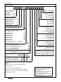
Ordering code
10 – 4X
B
*
5
Electrically operated
2-stage, 4-way servovalve:
with separate
electronics
= 4 WS 2 E
with integrated
electronics
= 4 WSE 2 E
Mechanical feedback
(standard for valves with
separate electronic amplifier
Electrical feedback
(standard for valves with
integrated electronics)
Barometric feedback
(spring centered)
M=
V=
=M
4
=E
A=
B=
C=
D=
E=
=B
Size 10 (NFPA/ANSI D 05)
= 10
Series 40 to 49
(40 to 49 externally interchangeable)
1
K8 =
= 2
= 5
= 10
= 20
= 30
= 45
= 60
= 75
Valves with separate electronics:
Coil no. 1 5 mA / 500 Ohm per coil
Coil no. 2 30 mA / 40 Ohm per coil (Standard)
Coil no. 3 7.5 mA / 200 Ohm per coil
Coil no. 4 20 mA / 80 Ohm per coil
Coil no. 5 50 mA / 28 Ohm per coil
3
K13 =
=1
=2
=3
=4
=5
315 =
Pilot supply and Valve Model: 4 WS 2 EM…
4 WS 2 EE…
drain
4 WSE 2 EM… 4 WS 2 EB…
4 WSE 2 EE… 4 WSE 2 EB…
Externally piloted, externally drained
Internally piloted, externally drained
Externally piloted, internally drained
Internally piloted, internally drained (standard)
available;
—mechanical or barometric feedback:
socket to size E 14 S–5 S
without mating plug
mating connectors RR00 011 921
(order separately)
Input pressure range to the first stage
feedback mechanical
145…4600 PSI (10…315 bar)
40 =
70 = electric or
140 = barometrical
210 = feedback
315 =
Valves with integrated electronics:
input signal: command value ± 10 mA / 1 kΩ NNNNNNNN = 8
command value ± 10 V / ≥ 50 kΩ (standard) N = 9
Spool overlap
0.5 to 1.5 % positive
0.5 to 1.5 % negative
3.0 to 5.0 % positive
0 to 0.5 % positive
0 to 0.5 % negative
Valves with integrated electronics:
— electrical feedback:
socket to size E 14 S–6 S
without mating plug
mating connectors RR00 013 159
(order separately)
K9 =
2
NBR seals
suitable for petroleum oils
(HM, HL, HLP)
FPM seals suitable for
phosphate ester fluids
(HFD-R)
Electrical connections
Valves with separate electronics:
socket to size 14 S–2 S
without mating plug
without electric socket
mating connectors RR00 002 460
(order separately)
= 4X
Flow
at a pressure drop across the valve of
pV = 1000 PSI (70 bar)
0.53 GPM (2 L/min)
1.3 GPM (5 L/min)
2.65 GPM (10 L/min)
5.3 GPM (20 L/min)
8 GPM (30 L/min)
12 GPM (45 L/min)
16 GPM (60 L/min)
20 GPM (75 L/min)
(tolerance band for the flow vs. signal function
is shown on page 10)
Further details
in clear text
{
145…580 PSI (10…40 bar)
580…1000 PSI (40…70 bar)
1000…2030 PSI (70…140 bar)
2030…3050 PSI (140…210 bar)
3050…4600 PSI (210…315 bar)
=–
=E
=T
= ET
= not available
Remarks:
Sandwich plate (X1→ X), must be ordered separately,
see page 16 item 19
Test unit for 4WSE (integrated electronics)
Model number VT-VET-1, Series 1X, data sheet RA 29 685
The test unit is used for the control and function monitoring of
integrated electronic valves.
4/16
Test unit for 4WS2 (battery driven)
Part number for ordering RR00 010 573,
see data sheet RA 29 680
Note: Test unit
— only for valves with separate electronics.
— only for coil numbers 1, 2 and 3.
— with electrical feedback only the maximum
flow will be signaled.
RA 29 586/06.98
Explanation of ordering code
1 Nominal flow
Barometric feedback system
The nominal flow is the flow in GPM (L/min) at nominal current
signal and at 1000 PSI (70 bar) pressure drop [500 PSI (35 bar) per
control land]. Other values will necessarily produce a different flow
rate.
The pilot pressure can not be higher than the maximum pressure
in the model code designation. The nominal flow refers to the mean
pressure of the relevant pressure stage and changes with the
pressure level.
The flow tolerance band and also the influences of saturation of
flows equal to or above 16.0 GPM (60 L/min) must be noted (see
page 10).
4 Spool overlap
The spool overlap given in % refers to the control spool stroke of
0.0315 inches (0.8 mm). For closed loop control, we recommend
an overlap close to zero or slightly negative, like the “E” spool
overlap.
If required, servo valves can be supplied with special operating
curves (with a subdued form, progressive, or with special spool
overlaps). Any special characteristics or parameters must be very
clearly specified.
Spool overlap “A”
This is the limit of the range for applications inclosed and open loop
controls. The 0 position flow is much less than for “D”.
2 Coil electrical control data
Spool overlap “B”
Mostly applied at pressures less than 2320 PSI (140 bar). Suitable
for position, force and pressure control in closed loop, it requires
a higher degree of damping than with spool “D”, and a greater 0
position flow is only of secondary importance.
The control signal must be generated from a current regulated
output stage.
The standard coil for valves with separate electronics is spool
number “2” (30 mA/40 Ω). With coil numbers 1, 3, 4 and 5, the
closed loop electronic control (servo amplifier) must be custom
matched with the valve.
Spool overlap “C”
Suitable for open loop or velocity control.
With integrated electronic controls, the signal value can be
supplied as a voltage signal – code “9”, or for long distances
[more than 82 ft (25 m) between the computer and the valve] as a
current signal – code “8”.
Spool overlap “D”
Suitable as a universal overlap for closed loop control of position,
force and velocity with low 0 position flow, however with lower
damping than that of spool “B”.
Spool overlap “E”
Suitable for highly accurate applications with a somewhat higher
0 position flow than with spool “D”. Main applications: control of
pressure and force in a closed loop.
3 Input pressure range to the 1st stage
The pilot pressure should be as constant as possible. Therefore,
it is often best to externally pilot the valve via port X1.
Mechanical feedback
Pilot pressure: 145 to 4600 PSI (10 to 315 bar)
5 Further details to be written in clear text
The pilot pressure should not be less than 60% of the system
pressure order to avoid reduction in the controllability, due to flow
forces on the valves control spool.
Special requirements should be specified here in clear text. After
the receipt of an order, this will be checked by the factory and the
valve code extended by an additional code when required.
Electric feedback
The pilot pressure should be kept within the pressure range where
possible. In order to influence the dynamic response of the valve,
it may be fed with a higher or lower pilot pressure. When the input
pressure of ≤ 580 PSI (40 bar), it is always better to keep pilot
pressure at port X1 equal to the system pressure at port P.
Symbols (simplified)
Servo valve with
integrated electronics
Servo valve for separate electronics
A
B
B
A
a, b
a, b
P
Mechanical
feedback M
Electrical
feedback E
a
b
0
P
T
Barometric
feedback B
B
A
B
A
T
P
T
a, b
a
b
0
P
T
B
A
a, b
a
b
0
P
a, b
T
5/16
RA 29 586/06.98
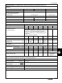
Technical data (For applications outside these parameters please consult us!)
General
Weight (approx.)
lbs (kg)
4 WS 2 EM 10 -4X/..
4 WS 2 EE 10-4X/
..with separate electronics
4 WS 2 EB 10-4X/..
4 WSE 2 EM 10 -4X/..
4 WSE 2 EE 10 -4X/
..with integrated electronics
4 WSE 2 EB 10 -4X/..
Additional items:
Sandwich plate for external piloting
(model "–", "T"), see page 15, item 16
Sandwich plate for external drain
(model "–", "E"), see page 15
Flushing plate, see page 15
Cable connections 6-1/2 ft (2 m) long
(for valves with separate electronics only)
each cable
2.42 (1.1)
4.19 (1.9)
3.53 (1.6)
2.65 (1.2)
4.41 (2.0)
3.75 (1.7)
0.66 (0.3)
0.55 (0.25)
2.2 (1.0)
0.44 (0.2)
Optional, however, the pilot pressure must be ≥ 145 PSI (10 bar) before start-up
Mounting position
Ambient temperature range
°F (°C)
–22 to +158 (–30 to +70) with external electronics
–22 to +140 (–30 to +60) for 4 WSE 2 E.10 (with integrated electronics)
Hydraulic, measured at ν = 149 SUS (32 mm2/s) and t = 104 °F (40 °C)
Feedback system
Mechanical
Electrical (Vp = 5) 1)
Barometric
Operating pressure range
ports A, B, P, X
PSI (bar)
145 to 4600 (10 to 315)
145 to 4600 (10 to 315)
(note pressure range)
145 to 4600 (10 to 315)
(note pressure range)
Return line pressure
ports T, Y
PSI (bar)
Pressure peaks <1450 (100)
static <145 (10)
Pressure peaks <1450 (100)
static <145 (10)
Pressure peaks <1450 (100)
static <145 (10)
(Return line pressure
reduces spool stroke)
Hydraulic fluid
Petroleum oil (HM, HL, HLP)
Phosphate ester fluids (HFD-R)
Fluid cleanliness
Maximum allowable fluid cleanliness level – Class 16/13, according to ISO 4406.
Therefore, we recommend a filter with a minimum retention rate of ß5 ≥ 100 without
bypass valve, with clogging indicator directly before the valve or as close as possible.
Fluid temperature range
°F (°C)
SUS (mm2/s)
Viscosity range
Nominal flow (QN)
GPM (L/min)
±10% at pV = 1000 PSI (70 bar) 2)
Flow in center pos. 5)
GPM (L/min)
control fluid for pilot stage
Pilot leakage & leakage
of whole valve 3), 4)
50 to +176 (10 to +80)
92 to 1760 (20 to 380); preferably 140 to 208 (30 to 45)
0.53
(2)
1.3
(5)
≈ 0.21 GPM
(0.8 L/min)
2.65
(10)
5.3
(20)
pv
1015 PSI (70 bar)
8.0
(30)
12.0
(45)
16.0
(60)
20.0
(75)
≈ 0.21 GPM (0.8 L/min)
pv
0.21 GPM (0.8 L/min) ≈ 0.21 GPM
+
1015 PSI (70 bar)
+ 0.04 • QN)
(0.8 L/min)
p
• 0.04 • QN
1015 PSI (70 bar)
The centered position flow data is valid only without an overriding dither signal; it will increase if dither is applied.
Hysteresis
(with dither optimized)
%
≤ 2.5
≤ 0.5
≤ 6 (pressure stage 40 and 70)1111
≤ 4 (pressure stages 140, 210, 315)
Reversal voltage
%
≤1.0
≤ 0.4
≤ 3.0
≤ 0.5
≤ 0.2
≤ 1.5
Sensitivity
%
Spool overlap: A
≥ 50% of p for 1% spool stroke (from the hydraulic null point)
Spool overlap: B, E
≥ 40% of p for 1% spool stroke (from the hydraulic null point)
Spool overlap: D
≥ 75% of p for 1% spool stroke (from the hydraulic null point)
Pressure gain
1)
Vp = electrical gain
4)
p = Operating pressure in PSI (bar)
2)
pV = pressure drop across valve in PSI (bar)
5)
3)
QN = Nominal flow in GPM (L/min)
The zero flow data is valid without overlapping dither signal
and increase with the dither part.
6/16
RA 29 586/06.98
Technical Data (For applications outside these parameters please consult us!)
Electrical
Feedback type
electrical (Vp = 5)
mechanical
barometric
Null compensation current
%
< 5, long term < 8
< 10, longterm < 15
Null offset, starting with a nullpoint
corrected valve with alteration of:
Fluid temperature
%
< 2 / 68 °F (20 °C)
< 4 / 68 °F (20 °C)
Ambient temperature
%
< 2 / 68 °F (20 °C)
< 4 / 68 °F (20 °C)
System pressure (0.8 to 1.2) x p in bar
%
<2
<1
<4
Return line pressure (0 to 0.1) x p in bar
%
<2
<1
<4
Insulation
Exceeds NEMA class B – special installation on request
Type of signal
analog
Coil number
1
2
3
4
5
Associated amplifier
(The amplifier card must
be ordered separately)
**
*
**
**
**
*With mechanical and barometric feedback use amplifier
Model SR 2, see RA 29 980, or amplifier Model VT 1600,
see RA 29 716. For electrical feedback use amplifier
Model SR 1, see RA 29 979, or amplifier Model VT 1610,
see RA 29 717.
**Please consult us for electronics.
Nominal current per coil
mA
8
9
integrated electronics
—
—
5
30
7.5
20
50
—
—
Ω
500
40
200
80
28
—
—
Inductivity at 60 Hz and100% nominal current
– Series circuit
H
– Parallel circuit
H
8.8
2.2
0.25
0.06
4.0
1.0
1.0
0.25
0.44
0.11
—
—
—
—
—
—
Resistance per coil
Recommended
dither signal: f = 340 Hz
The amplitude of the dither depends on the hydraulic
installation; maximum limit 10% of nominal current
current regulated
mA
—
—
—
—
±10
—
voltage regulated
V
—
—
—
—
—
±10
kΩ
—
—
—
—
—
1
Supply voltage (± 3%)
V
—
—
—
—
—
±15
Act. position value for spool setting
at 100% command value
V
—
—
—
—
—
approx. ± 10
(only Model
4WSE2EE 10...)
Command value
Input resistance
≥ 50
Electrical (inductive positional transducer) for external electronics
Electrical measuring system
Nominal spool stroke
Sensitivity with 4.5 kHz
carrier frequency
Resolution (static)
Differential transformer
inches (mm)
mV/V
in (mm)
± 0.31 (0.8)
1.7 (43)
continuous
Feed voltage (Veff) V
3.5
Carrier frequency kHz
4.5
7/16
RA 29 586/06.98
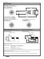
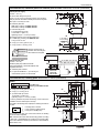
Plug-in connectors
For model 4WS2… (external electronics)
Plug-in connector – must be ordered separately
under part no. RR00 002 460;
For PIN allocation see below and
block circuit diagram on page 10
2.36
(60)
Ø 1.10
(28)
0.79 A/F
(20)
For model 4WSE2EM… and 4WSE2EB…
(integrated electronics) and model 4WS2EE…
(external electronics, inductive feedback)
Plug-in connector – must be ordered separately
part no. RR00 011 921;
For PIN allocation see below
4.09
(104)
For model 4WSE2EE… (integrated electronics)
part no. RR00 013 159;
For PIN allocation see below
Electrical connections: Model 4 WS 2 E.10... (valves for external electronics)
Pilot control (1st stage)
Positional transducer
Plug pin connections
Plug pin connections
green/yellow
blue
blue
green
A
A
B
D
C
B
E red
D
C
red
black
yellow
brown
Electrical connections to the servo valve can be made either in parallel, or in series. For safety, due to the lower inductivity obtained, we
recommend parallel connection.
Parallel connection:
For plug connection, connect A to B and C to D.
For cable connection, connect yellow to brown,
and green to white.
Series connection:
For plug connection, connect B to C.
For cable connection, connect brown to green.
An electrical input of A (+) to D (–) for plug connection, or yellow lead (+) to white lead (–) for cable connection, provides a flow direction
in the 2nd stage of P to A and B to T.
Reversing the direction of the current reverses flow direction in the 2nd stage, to P to B and A to T.
Warning: Connection A at the plug, or the white wire in the cable must not be connected (due to radio interference effects).
8/16
RA 29 586/06.98
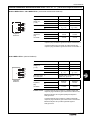
Electrical connections and technical data: Model 4 WSE 2E. 10... (Valves with integrated electronics)
Models 4 WSE 2 EM 10.. and 4 WSE 2 EB 10.. (mechanical and barometric feedback)
Re
A
B
C
D
E
Coil "8"
Coil "9"
Supply
voltage in V
(± 3 %)
A
+ 15 V
+ 15 V
B
– 15 V
– 15 V
C
0V
0V
Command value
D
± 10 mA
Re = 1 kΩ
± 10 V
Re ≥ 50 kΩ
maximum
100 mA
maximum
100 mA
±10 mA
≤ 0.2 mA
E
Current
required at
plug
connection
Integrated
electronics
Terminal connection
A
B
D
E
Command value: Command value at plug connection D, negative polarity with
respect to plug connection E gives a flow from P to B and A to T.
Command value at plug connection D, positive polarity with
respect to plug connection E gives a flow from P to A and B to T.
Model 4 WSE 2 EE 10.. (electrical feedback)
Re
Integrated
electronics
A
B
C
D
E
F
Terminal connection
Coil "8"
Coil "9"
Supply
voltage in V
(± 3 %)
A
+ 15 V
+ 15 V
B
– 15 V
– 15 V
C
0V
0V
Command value
D
± 10 mA
Re = 1 kΩ
± 10 V
Re ≥ 50 kΩ
E
Measured output
for control spool
F
Current
required at
plug
connection
A
B
D
Nominal stroke corresponds to ±10 V
against 0 V; Ri ≈ 4.7 kΩ
maximum
200 mA
maximum
200 mA
±10 mA
≤ 0.2 mA
E
Command value: Command value at plug connection D, negative polarity with
respect to plug connection E gives a flow from P to B and A to T.
Measured output F has a negative polarity with respect to
earth ground 0 V.
Command value at plug connection D, positive polarity with
respect to plug connection E gives a flow from P to A and B to T.
Measured output F has a positive signal with regard to
earth ground 0 V.
9/16
RA 29 586/06.98
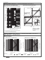
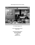
Operating curves: measured at ν = 190 SUS (41 mm2/s) and t = 122 °F (50 oC)
Flow vs. load function for all feedback systems
(Tolerance band ±10%) Note: Flows are calculated values
Tolerance zone for the flow-signal function
P
200
150
100
T
80
75
60
45
70
50
40
Nominal flow QN in L/min
A; B
110
Flow in %
100
60
Zero through break
according to spool 40
overlap
30
30
20
20
–100 –80
–60
20
–20
–40
Tolerance field
15
10
10
20
20
Typical flow curve
40
100
80
60
Command value in %
7
40
5
5
4
10
–5
60
3
2
2
5
80
10
1.5
1
0.8
Q = QN .
100
110
pv
P
1015 PSI (70 bar)
B; A
0.6
7 10
T
With flows of ≥ 16 GPM
(60 L/min), the effects of
flow saturation must be
observed.
15 20 30 40 50 70 100 150 200 300
Valve pressure drop pv in bar
pV = Valve pressure drop (input pressure minus return line
pressure minus load induced pressure)
Frequency response curves: measured at ν = 190 SUS (41 mm2/s) and t = 122 °F (50 oC)
Model 4 WS 2 EB 10.. and 4 WSE 2 EB 10..
Barometric feedback
0
–1
–100
–2
–100
–3
–90
–3
–90
–4
–80
–4
–80
–5
–70
–5
–70
–6
–60
–6
–60
–7
–50
–7
–50
–8
–40
–8
–40
–9
–30
–9
–30
–10
–20
–10
–20
–11
–10
–11
–10
0
–12
–12
1
Pressure stage:
10/16
2
3
••••••
5 7 10
20 30
Frequency in Hz
= 580 PSI
(40 bar)
•••
50 70 100
= 100 PSI
(70 bar)
Amplitude ratio in dB
–2
Phase lag in degrees
Amplitude ratio in dB
0
–1
0
1
= 2030 PSI
(140 bar)
2
3
5 7 10
Frequency in Hz
= 3050 PSI
(210 bar)
20
•
30
50
= 4600 PSI
(315 bar)
Phase lag in degrees
Nominal flow QN ≥ 12 GPM (45 L/min)
Nominal flow QN ≤ 8.0 GPM (30 L/min)
RA 29 586/06.98
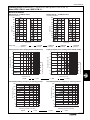
Operating curves, measured at ν = 190 SUS (41 mm2/s) and t = 122 °F (50 oC)
Model 4 WS 2 EM 10.. and 4 WSE 2 EM 10..
Mechanical feedback
Nominal flow QN ≤ 12 GPM (45 L/min)
Crossover functions
90
90
80
80
70
70
Stroke in %
100
Stroke in %
100
60
50
40
50
40
30
30
20
20
10
10
0
5
Pressure stage:
10
15
0
Time in ms
= 580 PSI
• • • • • • (40 bar)
5
0
15
10
= 100 PSI
(70 bar)
•••
0
0
–1
–1
–4
–90
–5
–60
–6
–30
–7
10
0
20
30
40 50
70
100
Phase lag in degrees
–120
150
Amplitude ratio in dB
1
–2
•
= ± 5%
–5
–60
–6
–30
0
–7
10
20
100
150
= ± 100%
Associated dependency of frequency on operating pressure
20
(50)
30 40 50
70
Frequency in Hz
= ± 25%
100
0
725
= 4600 PSI
(315 bar)
•
–90
100
40
15
–4
120
60
10
–120
120
80
= 3050 PSI
(210 bar)
5
–3
–90° Frequency in Hz
–90° Frequency in Hz
Associated dependency of frequency on operating pressure
15
0
Time in ms
–2
Frequency in Hz
Signal:
10
Frequency response curves, operating pressure 2030 PSI (140 bar)
1
–3
5
= 2030 PSI
(140 bar)
Frequency response curves, operating pressure 2030 PSI (140 bar)
Amplitude ratio in dB
60
Phase lag in degrees
Nominal flow QN ≤ 8 GPM (30 L/min)
Crossover functions
80
60
40
20
1450
2176
2901 3626 4641
0
725
(100)
(150)
(200) (250) (320)
(50)
•
= ± 5%
2176
2901 3626 4641
(100)
(150)
(200) (250) (320)
Operating pressure in PSI (bar)
Operating pressure in PSI (bar)
Signal:
1450
= ± 25%
= ± 100%
11/16
RA 29 586/06.98
Operating curves: measured at ν = 190 SUS (41 mm2/s) and t = 122 °F (50oC)
Model 4 WS 2 EE 10.. and 4 WSE 2 EE 10..
Electrical feedback system
Nominal flow QN ≤ 12 GPM (45 L/min,
electrical gain (amplification) Vp = 5
Crossover functions
90
90
80
80
70
70
Stoke in %
100
60
50
40
50
40
30
20
20
10
10
0
5
Operating pressure
10
15
0
Time in ms
5
10
0
15
= 580, 1015, 2031 PSI (40, 70, 140 bar)
Amplitude ratio in dB
Frequency response curves, operating pressure 2030 PSI (140 bar), Vp = 5
0
0
–1
–1
120
–4
90
–5
60
–6
30
0
200 300
50
100
Frequency in Hz
Signal:
•
Phase lad in degrees
–3
•
5
10
= 4570 PSI (315 bar)
120
–4
90
–5
60
–6
30
50
100
Frequency in Hz
0
200 300
= ± 100%
Associated dependency of frequency on operating pressure
–90° Frequency in Hz
200
150
100
50
150
100
50
0
145
580
1015
2031 3046 4600
0
145
580
1000
2030 3051 4600
(10)
(40)
(70)
(140) (210) (315)
(10)
(40)
(70)
(140) (210) (315)
Operating pressure in PSI (bar)
Signal:
•
Operating pressure in PSI (bar)
= ± 5%
15
–3
= ± 25%
200
12/16
15
0
Time in ms
–2
–7
10
= ± 5%
Associated dependency of frequency on operating pressure
10
Frequency response curves, operating pressure 2030 PSI (140 bar), Vp = 5
1
–2
5
= 3046 PSI (210 bar)
1
–7
10
–90° Frequency in Hz
60
30
Amplitude ratio in dB
Stoke in %
100
Phase lad in degrees
Nominal flow QN ≤ 8 GPM (30 L/min),
electrical gain (amplification) Vp = 5
Crossover functions
= ± 25%
= ± 100%
RA 29 586/06.98
Unit dimensions: dimensions in inches (millimeters)
Mechanical feedback / with separate electronics
Model 4 WS 2 EM 10-4X/… (standard)
Valve mounting bolts, not included
4) socket head cap screws
1/4-20 UNC x 2" (M6 x 50)
tightening torque = 7.67 lb-ft (10.4 Nm)
8
Top cover can be rotated 180°
9
Pilot stage (1st stage)
10
Second stage
11
O-ring (12 x 2 mm); Ports A, B, P, T
0.1 (2.5)
2.677 (68)
3
8
7
2.1
5
4
0.16 (4)
4
O-ring (7 x 1.5 mm); Port X1
10
Optional port X1 for external pilot
oil supply
Bore Ø 0.118 to 0.197 inches
(3 mm to 5 mm)
X1 Ø 0.39 (9.8);
If port X is to be used, the sandwich
0.043 (1.1)
12 13
plate must be used. (This plate
must be ordered separately)
Mechanical feedback / integrated electronics
Warning!
Port X1 is connected to pressure. If port X
Model 4 WSE 2 EM 10-4X/…
instead of X1 is to be used a sandwich
1
0.6 (15)
6.69 (170)
plate (order separately, see page 15)
Cover with integrated electronics
0.0004/4.0 in
0.01/100 mm
32
(Rmax 4)
2.953 (75)
3
Required surface finish
of interface when
mounting the valve
without our subplate
A/F = Across flats
2.2
Valve Mounting interface to ISO 4401-5, NFPA T3.5.1 M R1
and ANSI B93.7 D 05 except for port X1.
Subplates
G 66/12
G 67/12
G 534/12
G 535/12
G 536/12
(SAE-6; 9/16-18)
(SAE-8; 3/4-16)
(SAE-12; 1-1/16-12)
(SAE-12; 1-1/16-12)
(SAE-16; 1-5/16-12)
2.362 (60)
0.276 (7)
0.843 (21.4)
6.42 (163)
Ø 0.62 (15.7);
0.059 (1.5)
0.44 (11)
11
14; 8
2.83 (72)
14
0.51 (13)
1.575 (40)
Nameplate
12
2.992 (76)
9
7
13
0.6 (15)
3.189 (81)
6
0.83 (21)
TB
0.06 (1.5)
Interchangeable filter element
(10 mm A/F )
part no. RR00 306 842 (for NBR seals)
part no. RR00 306 843 (for FPM seals)
TA
3.82 (97)
5
B
A
4.41 (112)
Adjustment on both sides for setting
the “Null point” (centered position) of
the valve (allen wrench 3 mm A/F)
P
X1
6
1.024 (26)
4
Ø 0.26 (6.6)
2.24 (57)
Space required to remove plug
0.906 (23)
3
1.811 (46)
2.2 Plug type MS 3106 E 14 S-5 S
to integrated valve
Ordering code: RR00 011 921
1.28 (32.5)
2.1 Plug type MS 3106 E 14 S-2 S
to non-integrated valve
Ordering code: RR00 002 460
0.248 (6.3)
Zero point adjustment – remove plug
(2.5 mm A/F) to access the potentiometer to set the zero point
3.189 (81)
1
2.126 (54)
2 (50.8)
1.469 (37.3)
1.063 (27)
0.657 (16.7)
0.472 (12)
0.126 (3.2)
0.433 (11)
with port X
Subplates and valve mounting bolts must be
ordered separately, see RA 45 054
13/16
RA 29 586/06.98
Unit dimensions: dimensions in inches (millimeters)
Electrical feedback / integral electronics
Model 4 WSE 2 EE 10-4X/…
15
2.1
0.6 (15)
1.024 (26)
1.26 (32)
1.26 (32)
max. 2.6 (65)
4
2.05 (52)
3
2.3
0.945 (24)
2.09 (53)
0.945 (24)
2.76 (70)
2.2
1.024 (26)
Electrical feedback / external electronic control
Model 4 WS 2 EE 10-4X/…
3
Space required to remove plug
(take care with the connecting cable)
2.2 Plug compatible with Type MS 3106 E 14 S – 5 S
to non-integrated valve feedback RR00 011 921
4
Setting for hydraulic zero point
(allen key 3 A/F )
2.3 Plug compatible with Type MS 3106 E 14 S – 6 S
to integrated electronics RR00 013 159
15
Barometric feedback / external electronic control
Model 4 WS 2 EB 10-4X/…
Barometric feedback / integral electronics
Model 4 WSE 2 EB 10-4X/…
1.024 (26)
15
Lock nut 10 A/F
15
4
2.1
2.2
0.945 (24)
4
0.945 (24)
1.024 (26)
2.1 Plug compatible with Type MS 3106 E 14 S – 2 S
to non-integrated valve RR00 002 460
max. 1.693 (43)
1.26 (32)
2.1 Plug compatible with Type MS 3106 E 14 S – 2 S
to non-integrated valve RR00 002 460
2.2 Plug compatible with Type MS 3106 E 14 S – 5 S
to integrated electronics RR00 011 921
4
15
14/16
Setting for hydraulic zero point (allen key 3 A/F )
Lock nut 10 A/F
max. 1.693 (43)
1.26 (32)
RA 29 586/06.98
Unit dimensions, Sandwich plates for external pilot oil feed: dimensions in inches (millimeters)
External pilot oil supply
(models “–” and “T”)
0.276 (7)
P
0.61
(15.5)
The servo valve always has port X1.
If there is no X1 port on the mounting surface, the sandwich
plate (16) must be used with external pilot oil feed is required.
2.36
(60)
Either port X or X2 may be used.
16 Sandwich plate with
NBR-seals, ordering code RR00 319 482
FPM-seals, ordering code RR00 319 483
A
X
X2
0.437
(11.1)
B
TA
TB
17
18
0.311
(7.9)
0.787
(20)
3.35 (85)
17 Valve mounting bolts
4) socket head cap screws
1/4-20 UNC x 3" (M6 x 75)
tightening torque = 7.67 lb-ft (10.4 Nm)
19
18 Mounting surface for the sandwich plate (16)
19 1/4" BSP plug, ordering code RR00 001 973
O-ring 14 mm x 2 mm
G 1/4" (BSP);
0.47 (12) deep
0.492
(12.5)
20 O-ring (12 x 2 mm); ports A, B, P, T
21 O-ring (10.82 x 1.78 mm); port X
Required surface finish of
interface when mounting the
valve without our subplate
0.0004/4.0 in
0.01/100 mm
X
0.2
(5)
21
16
20
External pilot oil drain
(models “–” and “E”)
23
Sandwich plate (22) is not be used with
mechanical feedback or electrical feedback with
integrated electronics.
22 Sandwich plate included
23 For pilot oil feed Model "–", port X3 may be
used instead of port X1 for the oil feed.
1.06 (27)
(Rmax 4)
G 1/4" (BSP; 0.47 (12) deep
G 1/4" (BSP; 0.47 (12) deep
22
X3
Y
Y
2.2 (56)
32
X1
X2
0.984
(25)
only in valve type:
4 WS 2 EE...
4 WS 2 EB...
4 WS E 2 EB...
Unit dimensions, Flushing plate: dimensions in inches (millimeters)
Symbol
3.54 (90)
0.71 (18)
TB P X1 A
B
TB
2.126 (54)
2 (50.8)
1.469 (37.3
1.063 (27)
0.657 (16.7)
0.126 (3.2)
with NBR-seals
Ordering code RR00 308 492
19 O-ring (12 x 2 mm); ports A, B, P, T
20
0.079
(2)
20 O-ring (7 x 1.5 mm); port X
X1
21 4) socket head cap screws
1/4-20 UNC x 2" (M6 x 50)
tightening torque = 11.4 lb-ft (15.5 Nm)
In order to guarantee the perfect functioning of servo valves, the
installation must be flushed prior to start-up.
As a guide to the flushing time required, the following formula can
be used:
t≥
V
•5
Q
t = Flushing time in minutes
V = Tank contents in gallons (liters)
qV = Pump flow in GPM (L/min)
When refilling more than 10% of the tank contents, the flushing
process should be repeated.
Note: A directional control valve with mounting pattern according
to ISO 4401-5, NFPA/ANSI D 05 is better than a flushing plate.
Such a valve allows the actuator ports and lines to also be flushed.
Refer to RA 07 700.
B
A
1.811
(46) 1.563
(39.7)
2.76
(70)
P
0.969
(24.6) 0.531
(13.5)
TB
TA
0.47
(12)
Ø 0.276 (7)
21
1.811
(46)
0.47
(12)
1.58
(40)
0.39 (10)
19
15/16
RA 29 586/06.98
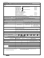
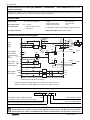
Control electronics for valve type 4WS2EM… and 4WS2EB…: servo amplifier SR 2 (must be
ordered separately)
A external servo amplifier is used to control the valve. This changes the analogue input signal (command value) in such a way that a
regulated current control of the servo valve can be effected using the output signal .
Technical data
V : ± 22 to 28 V smoothed
Supply voltage
– Height:
– Width conductor side:
– Width component side:
Imax: ± 60 mA
Max. output current
Card dimensions:
Eurocard 100 x 160 mm,
DIN 41 494
3 U (128.4 mm)
1 HP (5.08 mm)
7 HP
For applications outside these parameters, please consult us!
Front plate dimensions
Detailed information: Data sheet RA 29 980
Terminal connections / block diagram
1 Servo valve
current
28a
Input 1
Input 2
J9
30a
32a
Input 3
I
J10 Cu
2
PD
Cu
I
J6
16a
Signal voltage for
relays K1, K2, K3
14a
Controller changeover
+UL (L0)
=
(–VL)
L0
V14
+VL
(L0)
J12
H2
32c
Controller output
+24 V
0V
–24 V
A
24c
B
B
P
T
Enable
+VL (L0)
V33
V34
K1
3
Reserve
H3
10c
8c
PID
4
14c
5
+VL
16c
L0
20c
24a
A
J13
H1
28c
Actual value
C
6a
6c
30c
D
26c
16a
≈
2a
Nominal value
Supply voltage
± 22 to ±28 V =
K2
V
26a
–VL
10a
K3
8a
V37
12c
7815
V36
C16
C14
V28
C15
C13
V27
7915
6
18c
22c
+VL (L0)
Contact loading
V = 24 V / I = 0,5 A
+15 V
M0
–15 V
Relays K1 and K3 as well as the PID controller are special models and are
identified by a VT number when ordering.
Positive command value at port 30c gives a flow at the servo valve from P to B.
Positive command value at port 32a gives a flow at the servo valve from P to A.
Ordering code
VT-SR 2 S 1X
32-pin blade connector to DIN 41612 form D
(for installation in Euro-card racks and card holders)
*
=S
Series 10 to 19
= 1X
(10 to 19: unchanged technical data and connection allocations)
Further details in clear text
0=
1=
without ± 15 V voltage regulator
with ± 15 V voltage regulator
Mannesmann Rexroth Corporation
Rexroth Hydraulics Div., Industrial, 2315 City Line Road, Bethlehem, PA 18017-2131 Tel. (610) 694-8300 Fax: (610) 694-8467
Rexroth Hydraulics Div., Mobile, 1700 Old Mansfield Road, Wooster, OH 44691-0394 Tel. (330) 263-3400 Fax: (330) 263-3333
16/16
All rights reserved – Subject to revision
Printed in U.S.A.