1
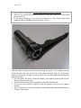
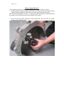
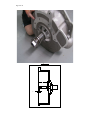
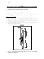
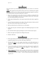
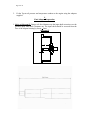
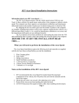
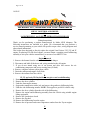
Page 1 of 11
16/03/05
MFK560C153, MFK560C168 AND MFK560CD
CHEVY V8 PETROL AND DIESEL
TO
LANDCRUISER 3, 4 & 5 SPEED PETROL TRANSMISSIONS
Fitting Instructions
Thank you for purchasing a product manufactured by Marks 4WD Adaptors. The
following instructions are intended as a guide. We recommend that you purchase a
service manual pertaining to your vehicle for specific torque values, wiring diagrams and
other related information.
This kit has been designed to directly replace the original Land Cruiser F155, 2F and 3F
engine. If replacing H or 2H diesel engine, you must obtain a complete petrol bellhousing
assembly to suit your vehicles transmission, or use one of our MFK371 kits.
A.
Engine Removal
1. Remove the bonnet from the vehicle and tie back the hinges.
2. Disconnect and label all the hoses and wiring attached to the old engine.
3. If you do not intend using one of our mount and drive kits remove the airconditioning compressor and power steering lines (if fitted).
4. Remove complete exhaust system from vehicle.
5. Drain the radiator and engine of all fluids.
6. Remove the radiator from the vehicle.
B.
1F, 2F, and early 3F fitted with the one-piece cast iron bellhousing.
1. Remove the bellhousing cover plate.
2. Remove the slave cylinder.
3. Undo the front engine mounts.
4. Support the transmission with a jack and remove the gearbox to bellhousing bolts.
5. Undo the side bellhousing mounts. NOTE: This applies to pre 08/80 vehicles only.
6. Remove the slave cylinder from the side of the bellhousing.
7. Remove the engine and bellhousing assembly from the vehicle using suitable engine
lifting equipment.
8. Remove the Landcruiser clutch.
9. Remove the flywheel.
10. Remove the bellhousing from the engine.
11. Remove the oil pressure and water temperature senders from the Toyota engine.
C.
Page 2 of 11
3F fitted with the Two-piece aluminium bellhousing and cast iron sandwich plate.
1. Undo the front engine mounts.
2. Support the transmission with a jack and remove the bellhousing bolts.
3. Remove the engine and bellhousing assembly from the vehicle using suitable engine
lifting equipment.
4. Remove the Landcruiser clutch.
5. Remove the flywheel.
6. Remove the sandwich plate from the engine.
7. Remove the oil pressure and water temperature senders from the Toyota engine.
D.
Transmission and Adaptor Kit Preparation
1. Remove the thrust bearing and carrier from the front of the gearbox.
Refer to diagram A for the next step.
2. Assemble the thrust-bearing carrier by first fitting the lock nut (4) onto the carrier (2)
then screw the carrier into the sleeve (5).
1. If your vehicle is fitted with the pressed metal thrust-bearing carrier and fork
remove the spring clip from the carrier.
2. The new carrier (2) has a groove machined in the back, sit the clip in the groove.
3. The bearing blocks (1) are then used to secure the spring clip. Fit the bearing blocks (1)
to the carrier (2) using the 4 x M4 counter sunk screws supplied in the kit. NOTE: Use
locktite on the screws.
Page 3 of 11
1. If your vehicle is fitted with a cast iron thrust-bearing carrier and fork.
2. There are two sets of flats machine into the new carrier the widest ones are used with
the cast iron fork.
3. Fit the bearing blocks (1) to the carrier (2) using the 4 x M4 counter sunk screws
supplied in the kit. NOTE: Use locktite on the screws.
Slide the thrust bearing extension carrier through the inside of the adaptor housing.
Ensure that the tube slides in and out of the adaptor housing with ease. If the thrust
bearing extension tube is tight, you may need to clean any burs inside the housing with
light emery paper.
3. Fill with grease the groove inside the middle of the adaptor housing and refit the
thrust bearing extension tube.
4. Press the thrust bearing (SF0914) onto the front of the extension tube.
5. Fit the two 10-mm dowels (MFC197) into the gearbox end of the new adaptor
housing.
6. Now is a good time to check the condition of the gearbox-input bearing and front seal.
If faulty, replace them.
Page 4 of 11
Diagram A.
3
4
1
2
3
5
1
6
E.
1F, 2F, and early 3F fitted with the one-piece cast iron bellhousing.
1. Fit the adaptor housing assembly to the Toyota petrol bellhousing using the original
bolts.
2. Fit the bellhousing and adaptor assembly to the gearbox.
Pre 08/80 vehicles.
1. Fit the bellhousing rubbers and bolts but do not tighten them. This will make the
engine mount set up procedure easier.
Cast iron clutch fork
3. Refit the clutch fork and retaining clips to the thrust-bearing carrier using the 2 clips
supplied in the kit.
4. Refit the slave cylinder.
5. Using silastic or a suitable gap sealer, seal the slot between the adaptor housing and
bellhousing. The slot is located on the driver side top of the housing. This hole was
once used as the timing inspection hole.
Page 5 of 11
Refer to diagram B and C.
This operation requires the slave cylinder push rod and clutch fork to be fitted.
6. Push the thrust bearing and carrier as far back as it will go. Measure the distance from
adaptor housing engine face (Dimension A) to the front of the thrust bearing.
This measurement should be 10-mm +-3-mm greater than the distance measured between
the engine rear face and the pressure plate fingers. Refer step I4.
7. Do not fit the input shaft extension to the transmission. This will make the engine
mount set up procedure easier.
Page 6 of 11
Diagram B.
A
C
Page 7 of 11
F.
3F fitted with the Two-piece aluminium bellhousing and cast iron sandwich plate.
1. Fit the adaptor housing assembly to the sandwich plate using the original bolts.
2. Fit the sandwich plate and adaptor assembly to the gearbox.
3. Refit the thrust-bearing carrier retaining clips to the clutch fork.
4. Using silastic or a suitable gap sealer, seal the slot between the adaptor housing and
bellhousing. The slot is located on the driver side top of the housing. This hole was
once used as the timing inspection hole.
Refer to diagram B and C.
This operation requires the slave cylinder push rod and clutch fork to be fitted.
5. Push the thrust bearing and carrier as far back as it will go. Measure the distance from
adaptor housing engine face to the front of the thrust bearing. This measurement
should be 8mm +-2mm greater than the distance measured between the engine rear
face and the pressure plate fingers. Refer step I4.
6. Adjust the length of the carrier to obtain the 8mm gap and then tighten the lock nut
using the spanner supplied in the kit.
Diagram C.
B
7. Do not fit the input shaft extension to the transmission. This will make the engine
mount set up procedure easier.
Page 8 of 11
H.
Engine Mount Set Up
The most accurate way of determining the position of the new mounts is to trial fit the
engine.
NOTE: If this engine kit is being fitted to FJ40 or FJ55 series Landcruisers the original
bellhousing will be very close or may contact the front transmission tunnel fire wall area.
To rectify the problem some panel beating may be required.
1. Remove the original chassis mounts from the chassis by drilling or grinding the heads
of the rivets then drifting the rest of the rivet through the chassis rails. If the mounts
are welded simply grind them off the chassis.
2. Fit the engine mounting rubbers to the engine using the bolts and washers supplied in
the kit.
3. Loosely fit the chassis brackets to the rubbers. The smaller bracket is fitted to the left
side of the vehicle and the larger one on the right side.
4. Make sure that the dowels are fitted to the rear of the engine.
5. Guide engine into place and bolt the engine to the bellhousing using the new bolts
supplied.
6. Once satisfied with the engines positioning tack weld or bolt the mounts in place.
7. Remove the engine and complete the welding of the mounts.
8. Paint the welded area.
I.
GM Engine Preparation
1. Fit the spigot bearing (6202) into the spigot bearing adaptor (MFC971) then fit the
completed assembly to the rear of the crank using a suitable drift.
2.
Bolt the GM flywheel to the engine using loctite on the bolts and torque to
specification. NOTE: It is advisable to have the flywheel machined if fitting a new
clutch kit.
3.
Fit the clutch assembly to the flywheel using the input shaft extension supplied with
the kit as a clutch aligning tool. Note: The standard 11" Chevy clutch kit is
recommended.
4.
Refer to diagram C. With the clutch kit fitted to the flywheel take a measurement
from the highest point on the pressure plate fingers to the rear of the engine block
This dimension should be 10-mm +-3-mm less than the dimension obtained from
step E6, or F5.
Page 9 of 11
5.
Fit the Toyota oil pressure and temperature senders to the engine using the adaptors
supplied.
J.
Final Adaptor Preparation
1. Refer to Diagram B. Using a soft faced hammer tap the input shaft extension over the
gearbox input shaft until it bottoms out. The input shaft should be recessed from the
face of the adaptor housing by 8 mm + 3mm.
Diagram B.
A
C
Page 10 of 11
NOTE: The input shaft extension shown in the diagram above will only suit the spigot
bearing support (6202) which is a ball race used with the adaptor ring (MFC971). This
input shaft was introduced in May 1997. Measures 195mm +-.5mm.
If have an input shaft manufactured prior to this date then it will measure approximately
15mm longer than this one and must be used with the original GM bronze bush, part
number 92020434.
K.
Engine Installation
1. Put the gearbox into 4th gear and the transfer case into high range. Raise one of the
rear wheels off the ground.
2. Guide the engine into place and rock the back wheel backward and forward to help
with the gearbox spline alignment into the clutch plate. Once aligned secure the
engine using the bolts, spring washers, and flat washers supplied.
3. Lower the engine over the engine mounting rubbers and tighten all of the bolts once
aligned.
4. Fit the new flywheel cover plate to the front of the adaptor housing using the bolts
and washers supplied.
5. The engine is now sitting higher than the Toyota engine. This is to give the required
legal sump clearance over the front diff. NOTE: A rear drop sump must be used for
this conversion.
For cast iron bell housings only.
1. Fit the original Toyota cover plate to the underside of the Toyota petrol bellhousing
using the original bolts.
6. Check the Hi-Low lever for correct operation, a small bend in the lever may be
required to clear the hole in the floor.
7. Modify the radiator spouts to correspond with the new engine outlets.
8. Fit the heater and radiator hoses.
9. Fit the power steering pump and air-conditioning compressor if required. NOTE:
Brackets will need to be fabricated if you are using the Toyota accessories.
10. If you plan on using a different grade fuel, drain the fuel tank and fuel lines.
11. Put 20 liters of the correct fuel into the tank.
12. Complete the wiring.
Page 11 of 11
13. Complete the exhaust system. NOTE: Heat shields must be fitted to the exhaust
system to prevent excessive heating of the engine mounting rubbers and clutch slave
cylinder. Failure to do so will cause premature engine mounting failure and possible
clutch failure in hot off road conditions.
14. Check all fluid levels.
15. Double check all mounting bolts are tight.
16. Start engine and check forFuel leaks.
Oil leaks.
Water leaks.
Exhaust leaks.
Allow the engine to warm up and recheck above.
17. Refit the bonnet.
The components supplied in the kit are designed for specific type conversions.
Modifications to any components without the written consent from Marks 4WD Adaptors
will void any possible warranty or return privileges. Should you have any further
questions that are not covered in the instruction sheet, please contact our sales department
for assistance.
Remember an inexpensive phone call can save a costly mistake!
Proudly Manufactured by:
Marks 4WD Adaptors
1-3 Ventura Road, Dandenong South, Vic. 3175
Tel: (03) 9702 7366, Fax: (03) 9702 7566,
E-Mail: [email protected]
Internet catalogue: http://www.marks4wd.com