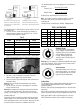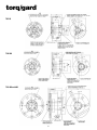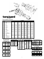
1
Dear Colleague,
Thank you for visiting our website and downloading a product catalog from the R.M.
Hoffman Company. We hope this information will be useful to you in solving the
application you are working on.
The R.M. Hoffman Company is located in the Silicon Valley and has been in business for
over 50 years. We are engineers who specialize in mechanical components such as
gearboxes, flex couplings, rotary unions, and torque releases, as well as hardware items
such as actuators, brakes, clutches, and electrical slip rings. We sell our solutions worldwide to semiconductor, medical, packaging, robotic machine and other builders.
Quite often we find that our customers want a customized version of standard product
offerings and we take pride in our ability to help match our customer’s engineering
requirements to the exact product needed. We work closely with our customers to
provide modified products or an assembly of products.
Please give us a call and let us know how we can assist you. We look forward to talking to
you soon.
Thank you.
The R.M. Hoffman Team
408-739-6580
info@rmhoffman.com
R.M. Hoffman Company • 159 San Lazaro Avenue, Sunnyvale, CA 94086 • 408.739.6580 • [email protected] • www.rmhoffman.com
SERVICE MANUAL
TORQ-GARD™ OVERLOAD CLUTCH
The Driving Force in Automation
WARNING
This is a controlled document. It is your responsibility to deliver this information to the end user of the
CAMCO/FERGUSON product. Failure to deliver this could result in your liability for injury to the user or
damage to the machine. For copies of this manual call your Customer Service Representative 800-645-5207.
™
torq/gard
mechanical
torque-limiting
overload clutch
Installation–Operation
and Maintenance Instructions
1. Read your Torq-Gard Installation-Operation Instructions
thoroughly before operating the unit, for your safety and the
protection of your equipment.
2. Double check to be sure the power is off and cannot be turned
on while working on the equipment.
3. Electrical power should be disconnected at the fuse box, circuit
breaker or motor starter.
4. The Torq-Gard Clutch is designed to protect your machine and
will not protect against bodily injury.
5. Keep all objects such as hands, clothing, tools, etc. away from
rotating or moving parts.
6. Use safety glasses or equivalent to protect your eyes.
7. Do not manually re-engage the Torq-Gard Clutch. (Refer to
“Automatic Reset” instruction.)
8. Do not adjust the torque while the clutch is disengaged. (Refer
to “Torque Setting” instruction.)
9. Do not exceed the recommended maximum RPM. (Refer to
Torq/Gard Rating Chart.)
10. The detector mechanism must electrically disconnect the prime
mover at the recommended RPM settings. (Refer to “Overload
Detection” instruction.)
11. Shaft mounting set screws must clear the mounting bosses or
the clutch will not release upon overload. (Refer to “Mounting
the Torq/Gard” instruction.)
12. Shaft and detector mounting set screws must be tight and the
recommended number used. (Refer to “Mounting the Torq/Gard”
instruction.)
The above list includes major safety points to be observed, but
should not be considered as limiting in safety precautions to be
followed.
Browning Torq/Gard single strand sprockets, for No. 40, 60, 80, and
100 ANSI Standard Roller Chain Drives, mount directly to the clutch.
Browning Torq/Gard Gearbelt Pulleys are also available for 1/2”
Pitch Belts.
Before mounting the clutch on the driving or driven shaft, your choice
of coupling or sprocket should be attached to the Torq/Gard Clutch.
Sprocket Installation
Browning Torq/Gard Single Strand
Sprockets register with the drilled and
tapped mounting lugs on the adapter
end of clutch. Torq/Gard Chain Drives
can be used as the driving or driven
member. See page 6 for sprocket
availability.
1. Place the sprocket on the registered
mounting lugs.
2. Select the correct length Hex. Head
Cap Screws (3 required) from Table A.
Warning: Short Screws may strip the mounting lug threads.
3. For maximum locking effect, (medium) spring lock washers
should be used under the Hex. Head Cap Screws.
Table A–Sprocket Mounting Hardware
TG3/6
TG20
TG60
TG200
TG400
TG800
Operating Principle
TG35A__K
20TG40A__K
TG40A__K
TG60A__K
TG80A__K
TG100A__K
#8-32 X .50 HHCS
#10-24 X .62 HHCS
1/4-20 X .75 HHCS
3/8-16 X 1.00 HHCS
1/2-13 X 1.50 HHCS
1/2-13 X 1.75 HHCS
Gear Belt Pulley Installation
Torq/Gard Overload Clutches help protect the entire drive train of
your machinery from damage due to excessive torque generated by
overloads and jamming. The torque is adjusted by turning the single
hex-socket head control which adjusts the Torq/Gard Clutch
precisely to any setting within its load range. A spring-loaded cam
follower seated in a single hub cam detent causes the hub and
clutch body to rotate as a unit. The two point contact of the follower
produces equal forces within the cam detent, minimizing the effect
of “breathing”, found in conventional clutches. When the pre-set
torque limit is exceeded by an overload condition, the follower is
instantly released from the cam detent, disconnecting the hub from
the body. Either the hub or the body may be used as the input or
output.
NOTE: During overload, the Torq/Gard produces a loud audible
report, which is a normal operating characteristic of the clutch.
In direct coupled applications, the modular designed Torq/Gard can
be used with Browning Ever-Flex Couplings or Chain Coupling Kits,
without modification to the clutch or couplings. Split taper bushings
are available for the coupling output.
Follow the above mounting instructions for the Browning Torq/Gard
Gear Belt Pulleys, using the longer Hex. Head Cap Screws supplied
with the pulleys.
Chain Coupling Installation
1. Select the Browning Chain Coupling
components from page 6 for the
applicable Torq/Gard Model.
2. Mount the single strand sprocket per
the above “Sprocket Installation”
instructions.
3. Place the Split Taper Bushing
Sprocket over the Single Sprocket,
with the corresponding teeth in
alignment.
4. Secure the two sprockets by wrapping the double strand roller
chain around the sprockets, insuring that the sprocket teeth fully
engage the chain.
2
5. Insert the chain connecting link in the chain ends and lock with
the spring clip (supplied with the connecting link).
When assembled correctly, the Split Taper Bushing Sprocket will
“float”, for maximum misalignment capability.
Table B–TGC60 Clutch
Detector End
Set Scr. Length (2) Reqd.
Shaft Dia.
to Retain Detector Cam
.750 Dia.
.190-32UNF-2A x .75 Lg.
.9375 Dia./1.125 Dia. .190-32UNF-2A x .62 Lg.
1.250 Dia.
.190-32UNF-2A x .50 Lg.
Ever-Flex Coupling Installation
1. Select the correct Ever–Flex Coupling
and Adapter Plate from page 6.
2. Attach the Adapter Plate to the
Torq/Gard mounting lugs with three
(3) Allen Flat Head Cap Screws
supplied with the adapter.
3. Mount the Ever-Flex half coupling on
the Adapter Plate with the eight (8)
Hex. Head Cap Screws supplied with
the Adapter Plate.
(Quantity 10 Hex. Head Cap Screws are supplied with Adapter Plate
400CAP9 and 800CAP10.)
Set Scr. Length (1) Reqd.
to Retain Detector Cam
Over Key
.190-32UNF-2A x .38 Lg.
.190-32UNF-2A x .38 Lg.
.190-32UNF-2A x .38 Lg.
Adapter End
Set Scr. Length (2) Reqd.
@ Adapter End
Shaft Dia.
of Clutch
.750 Dia.
.190-32UNF-2A x .50 Lg.
.9375 Dia./1.125 Dia. .190-32UNF-2A x .38 Lg.
1.250 Dia.
.190-32UNF-2A x .25 Lg.
Set Scr. Length (1) Reqd.
Over Key @ Adapter
End of Clutch
.190-32UNF-2A x .19 Lg.
.190-32UNF-2A x .19 Lg.
.190-32UNF-2A x .19 Lg.
Table C–TGC200 Clutch
Detector End
Mounting The Torq/Gard
The Torq/Gard Clutch hub is machined
to its maximum bore diameter. Shafts
smaller than the maximum diameter are
accommodated with standard Browning
Torq/Gard Bushing Kits as shown on
page 6. The bushing kits are complete
with bushing, key and shaft set screws.
Note: Six (6) set screws are supplied in
four (4) lengths.
Warning: The correct length set screws
must be used as the clutch will not
release if the set screws extend beyond
the hub and hit the adapter mounting lugs.
The Torq/Gard Clutch can be shaft mounted from the adapter or
detector end of the hub. The required shaft set screw lengths vary
depending on the bushing selected. They will also vary in length if
used on the detector end in conjunction with the detector
mechanism.
Tables B, C and D include all set screw combinations for any
bushing or mounting option.
Example 1:
A TGC60 Clutch requires a .750 inch diameter shaft mounted on the
adapter end.
Selection: A Browning 60BU012 Bushing Kit is chosen from page 6.
The correct set screws from Table B (adapter end):
Qty. 2 .190-32UNF-2A x .50 Long
Qty. 1 .190-32UNF-2A x .19 Long (over key)
Example 2:
A TGC60 Clutch requires a .750 inch diameter shaft mounted on the
detector end with the detector mechanism.
Section: A Browning 60BU012 Brushing Kit.
The correct set screws from Table B (detector end):
Qty. 2 .190-32UNF-2A x .75 Long
Qty. 1 .190-32UNF-2A x .38 Long (over key)
NOTE: If the Bushing was used on the detector end without the
detector, the selection would be the same as Example 1.
Shaft Dia.
.9375 Dia./1.250 Dia.
1.250 Dia./1.500 Dia.
1.500 Dia./1.750 Dia.
1.750 Dia./1.9375 Dia.
Set Scr. Length (2) Reqd.
to Retain Detector Cam
.250-20UNC-2A x 1.0 Lg.
.250-20UNC-2A x .88 Lg.
.250-20UNC-2A x .75 Lg.
.250-20UNC-2A x .62 Lg.
Shaft Dia.
.9375 Dia./1.250 Dia.
1.250 Dia./1.500 Dia.
1.500 Dia./1.750 Dia.
1.750 Dia./1.9375 Dia.
Set Scr. Length (2) Reqd.
@ Adapter End
of Clutch
.250-20UNC-2A x .75 Lg.
.250-20UNC-2A x .62 Lg.
.250-20UNC-2A x .50 Lg.
.250-20UNC-2A x .38 Lg.
Set Scr. Length (1) Reqd.
to Retain Detector Cam
Over Key
.250-20UNC-2A x .50 Lg.
.250-20UNC-2A x .50 Lg.
.250-20UNC-2A x .50 Lg.
.250-20UNC-2A x .50 Lg.
Adapter End
Set Scr. Length (1) Reqd.
Over Key @ Adapter
End of Clutch
.250-20UNC-2A x .25 Lg.
.250-20UNC-2A x .25 Lg.
.250-20UNC-2A x .25 Lg.
.250-20UNC-2A x .25 Lg.
Table D–TGC400 and TGC800 Clutch
Detector End
Set Scr. Length (2) Reqd.
Shaft Dia.
to Retain Detector Cam
.375 Dia./1.688 Dia. .375-16UNC-2A x 1.25 Lg.
1.750 Dia./2.125 Dia. .375-16UNC-2A x 1.00 Lg.
2.125 Dia./2.4375 Dia. .375-16UNC-2A x .88 Lg.
Set Scr. Length (1) Reqd.
to Retain Detector Cam
Over Key
.375-16UNC-2A x .62 Lg.
.375-16UNC-2A x .62 Lg.
.375-16UNC-2A x .62 Lg.
Adapter End
Set Scr. Length (2) Reqd.
@ Adapter End
Shaft Dia.
of Clutch
1.375 Dia./1.688 Dia. .375-16UNC-2A x .88 Lg.
1.750 Dia./2.125 Dia. .375-16UNC-2A x .62 Lg.
2.125 Dia./2.4375 Dia. .375-16UNC-2A x .50 Lg.
Set Scr. Length (1) Reqd.
Over Key @ Adapter
End of Clutch
.375-16UNC-2A x .38 Lg.
.375-16UNC-2A x .38 Lg.
.375-16UNC-2A x .38 Lg.
1. Select the Browning Torq/Gard Bushing Kit from page 6.
2. Refer to tables B, C or D for the correct shaft set screws.
(3 required)
3. Slide the bushing with the mating key on the shaft.
Note: The use of LOCTITE C5 - Anti-Seize lubricant is
recommended to ease assembly of the bushing to the shaft
and the Clutch to the bushing.
4. The shaft length must be at least equal to the bushing length to
insure engagement of the Torq/Gard bearings. Limited shaft
lengths or high overhung load applications require additional
outboard bearing support. Browning Bushings are manufactured
specifically to fit the entire length of the hub which provides
additional support. Again, check Tables B, C or D to insure that
the correct length set screws are used and that they will engage
the shaft.
5. Apply Perma-Lok HM118 to the set screws and mating tapped
holes in the Clutch hub.
3
Warning: High inertia loads, reversing loads, excessive vibration or
continual tripping may require the use of Perma-Lok HM160.
6. Tighten set screws against shaft and key.
Warning: Check to insure that the set screws do not extend
beyond the hub on the adapter end. When used on the detector
end the set screws must also engage the detector cam, but must
not extend beyond the detector cam.
Typical Wiring Diagram
Overload Detection
The axial movement of the Detector
Mechanism, when used in conjunction
with a limit/prox. switch, electrically
disconnects the prime mover (motor)
from the load.
The Detector Mechanism consists of a
spring loaded plate mounted on the
clutch cover plate cam. When an
overload occurs, the cam releases the
detector plate a sufficient distance to
actuate a limit/prox. switch. When the overload has been cleared, the
re-engagement of the clutch automatically resets the detector
mechanism. Warning: Detector systems are recommended on all
applications and mandatory on the following:
Figure 3
6. The detector mechanism can be installed in the field.
A. Place the three (3) detector springs in the three shallow
holes in the Torq/Gard cover.
B. Place the “white” detector plate guide pins in the three deep
holes in the cover.
Note: The pins are registered to fit in one position only.
C. Place the “black” detector cam on the clutch hub with flat
side up.
D. Rotate the cam until each cam lobe is directly over the
detector plate ears and the set screw holes are aligned
with the set screw holes in the hub.
Note: The clutch must be in its engaged position for proper
alignment of the detector mechanism.
E. Secure the detector cam to the clutch hub with the correct
length set screws, using Perma-Lok HM118. (Refer to
Tables B, C or D for the correct shaft set screws.)
Warning: Factory mounted detector mechanisms utilize set
screws for shipping purposes only. The correct length of the set
screws is determined by the shaft diameter used.
TG60/TG200 - At speeds over 100 RPM
TG-400/TG800 - At all speeds
Infinitely high shock loads can occur, depending on the type of jam
or overload. The detector system further protects your equipment
under these conditions. On high inertia applications, breaking the
prime mover may have to be considered.
1. The limit/prox. switch must have a rigid mounting.
2. Locate the limit/prox. switch so the detector plate travel will
acuate the limit/prox. switch.
Note: Refer to Figure 1 and Figure 2 for typical installations. Figure 1
mounting is preferred for reasons of rigidity.
Figure 1
Torque Setting
The torque is infinitely adjustable within the nameplated torque
limits of the clutch. Determine the operating and tripping torque
required to drive your machine.
A. Operating torque is the normal full load torque required by
the application.
B. Tripping torque, which is usually higher than operating
torque, depends on the starting torque requirements of
the application and the location of the Torq/Gard Clutch.
C. Mounting the clutch away from the motor tends to absorb
peak starting torques through power transmission and
machine components. (Refer to Fig. 4.)
D. Tripping torque should be set higher than the point at
which the clutch will “nuisance trip” on starting, but
below the maximum torque value the machine can
safely absorb.
Figure 2
3. Refer to the Torq/Gard dimension prints on page 5 for the
detector plate “travel”.
4. When mounting the limit/prox. switch, consult the
manufacturer’s specifications for pre-travel and overtravel.
5. Wire the limit/prox. switch in parallel with the “start” contactor
to permit motor starting after the overload has been cleared.
Note: Refer to Figure 3 “Typical Wiring Diagram”. Limit/prox.
Switches are available with additional contacts to further acuate
warning alarm systems.
Figure 4
Direct Drive application with the Torq/Gard
mounted on the low speed output shaft of
the reducer. The Torq/Gard is shown with a
Browning Ever-Flex half coupling which
mounts on the clutch adapter without
modification. Browning Chain Coupling Kits
are also available for the Torq/Gard when
greater misalignment capabilities are
required. Either side of the Torq/Gard can be
used as the input.
4
The Torq/Gard should not be used on the
high speed input side of the reducer.
Clutch sensitivity becomes a function of
the reducer’s gear ratio. As an example,
when used with a 100 to 1 reducer, a 100
inch-pound torque variation on the output
side will reflect only a 1 inch-pound
change on the input side. Do not exceed
the maximum RPM shown in the
Torq/Gard selection table.
The Torq/Gard may also be sized by applying one of the following
formulas:
Torque (In.-lbs.) = Horsepower (HP) x 63025
RPM
OR Horsepower =
Mounting the clutch on the output of the
gear motor or reducer provides the most
economical clutch assembly. The Torq/Gard
is designed to protect the weakest link in
the drive system.
Tripping Torque = Operating Torque x Service Factor
Note: The nameplate contains a sensitized “rectangle” on which
the torque setting may be recorded with ball point pen or a
numbering die.
Warning: The Torq/Gard Clutch is not a “FAIL SAFE” device and
cannot be used on “overhauling” or “holding” load applications.
The Torq/Gard is mounted on the driven
machine and powered through a chain and
sprocket drive. Mounting the clutch in this
position tends to absorb peak starting torques.
TORQ / GARD RATINGS
The Torq/Gard Clutch is delivered with the torque set at the low end
of its torque range.
1. Turn the single Hex.-Socket Head adjusting nut clockwise to
increase the Torque Setting. (Refer to Table E.) Note: 1/2 inch
Hex-Keyed (Allen) Wrench is required.
Torque (in.-lbs.)
Table E
MODEL
TG-3
TG-6
TG-20
TGC60
TGC200
TGC400
TGC800
APPROXIMATE TORQUE
(IN.-LBS.) PER TURN
2.67
4.4
11
50
100
225
450
Torque (In.-lbs.) x RPM
63025
MAXIMUM
TURNS
7.5
7.5
13
8
11
9
9
HP
RPM
Weight
Inertia
Models
Min.
Max.
Max.
Max.
(lbs.)
(WK2)
Max. (inches)
Bore Dia.
TG-3
13
32
1.5
1800
1.5
1.4
1/2
TG-6
23
56
2.5
1800
1.5
1.4
1/2
TG-20
56
203
4
1800
2.5
5.7
3/4
TGC 60
200
600
8.5
900
5.5
10
1-1/4
TGC 200
600
2000
21.5
680
12
46
1-15/16
TGC 400
2000
4000
22.2
350
38
455
2-7/16
TGC 800
4000
8000
44.4
350
38
455
2-7/16
Automatic Reset
The Torq/Gard Clutch is automatically
reset by “jogging” the motor after the
overload has been corrected. At speeds
under 50 RPM the Torq/Gard will
re-engage, without jogging, upon
starting the motor. The clutch will not
re-engage if the overload exceeds the
torque setting.
Warning: Do not re-engage the Torq/Gard manually. When the clutch
snaps into engagement, injury could occur if the operator’s hand is
near a chain and sprocket or belt drive.
2. Sighting the front face of the adjusting nut with the Torque Meter
Lines on the nameplate indicates the approximate torque setting.
Single Position
The Torq/Gard always resets in the same
position when tripped. It is an excellent
choice in applications that must remain
registered or timed. All Torq/Gard
Clutches are fully reversible.
3. The “Min.” line on the nameplate is the point at which the
adjusting nut is threaded. Before setting the torque, Perma-Lok
HM118 should be applied to the exposed threads.
4. The first line on the Torque Meter beyond “Min.” represents the
low torque setting.
Warning: The clutch should not be operated at torque settings
below this “line”.
5. Do not set torque if the clutch is disengaged as an erroneous
torque setting will result.
Warning: Do not remove the adjusting nut. Extremely fine threads
are used to reduce the possibility of the adjusting nut losing its
setting. If the adjusting nut is removed for any reason, (including
lubrication) upon replacing, hand thread the first few turns or cross
threading may occur.
Tripping torque can be established by progressively increasing the
torque setting until the clutch no longer trips under starting loads.
If the tripping torque value is known, the clutch may be pre-set with
a torque wrench or a torque arm and calibrated spring scale.
Lubrication
The Torq/Gard is factory lubricated with Mobilith AW2 and does not
require additional lubrication for many years, under normal
operating conditions.
Clutches used in extreme operating applications may be opened for
regreasing.
Open clutch for greasing by removing torque adjusting nut, detector
system, cover bolts and then tap hub end opposite cover with a soft
hammer. “Do not pry open at cover split line”.
Apply grease (AW2 or equiv.) to hub bearing journals, hub cam
track, follower, thrust washer surfaces and all needle bearings.
5
™
torq/gard
TGC 60
TCG 200
TGC 400 and 800
6
™
torq/gard
Parts List (Models TG and TGC)
Item
1
2
2
3
4
5
6
7
8
9
10
11
12
13
14
15
16
16A
17
18
19
20
20
21
22
Qty
1
1
1
1
1
1
1
2
1
1
1
2
2
2
1
1
1
1
1
3
2
5
7
1
2
Description
Adjusting Nut
Spring
Spring
Button
Body
Lever
Dowel Pin
Bearing
Dowel Pin
Bearing
Gasket
O-Ring
Bearing
Thrust Washer
Drive Hub
Cover
Detector Plate
Prox Detector Plate Assy
Cam-Detect Plate
Spring
Roll Pin
Hex HD Cap Screw
Hex HD Cap Screw
Soc HD Set Screw
Soc HD Set Screw
SINGLE STRAND SPROCKETS
ANSI Standard Roller Chain
FOR NO. 40, 1/2” PITCH
Model
TGC60
Sprocket
Part No.
TG40A26K
TG40A36K
TG40A45K
TG40A60K
TG40A72K
No.
Teeth
26
36
45
60
72
FOR NO. 60, 3/4” PITCH
TG60A26K
26
TG60A36K
36
TGC200
TG60A45K
45
TG60A60K
60
TG60A72K
72
FOR NO. 80, 1” PITCH
TG80A28K
TG80A36K
TGC400
TG80A45K
TG80A60K
TG80A72K
3
A-58211
A-58255-1
A-58168
D-58675
B-58202
A-58159
A-61684
A-58158
A-61685
A-58173
A-58182-1
A-61683
A-58172
B-58609
B-58250
B-58794
B-58795
A-53740-4
A-26023-35
A-26015-17
A-26005-16
A-26005-17
6
A-58211
A-58255-2
A-58168
D-58675
B-58202
A-58159
A-61684
A-58158
A-61685
A-58173
A-58182-1
A-61683
A-58172
B-58609
B-58250
B-58794
B-58795
A-53740-4
A-26023-35
A-26015-17
A-26005-16
A-26005-17
20
A-58238
A-58255-3
A-58171
C-58695
B-58236
A-58165
A-61687
A-58164
A-61688
B-58181
A-58182-2
A-61686
A-58174
B-58668
B-58260
B-58383
B-58385
A-53052-4
A-26023-37
A-26015-23
A-26005-16
A-26005-17
PART NUMBER
60
A-16512
A-15731
A-15727
D-65632
B-16510
A-17647
B-15732-1
A-17650
A-15730-1
B-73040
A-15729-2
B-15732-3
A-16511
B16506
C-65649
B17056
B-71122
B-17055
A-17059
A-73403-1
A-18874-2
A-26005-39
A-26005-40
200
A-16346
A-13732
A-13407
D-65927
C-13401
A-17648
A-14407
A-26007-37
A-14409
C-73044
A-14399
A-14408
B-13406
C-76760
D-65879
C-16927
C-71123
B-76762
A-16989
A-73403-2
A-26002-15
A-26005-45
A-26005-46
400
B-16680
A-16682-1
A-16682-2
A-16685
D-18715
C-16677
A-26007-89
B-15732-4
A-26007-65
A-16683
C-16679
A-15729-3
B-15732-5
B-16681
D-18719
D-16675
C-17076
C-71126
C-17077
A-17788
A-26023-71
A-18876-2
A-26005-77
A-26005-79
TORQ / GARD BUSHING KITS
Model
TGC60
Shaft
Dia.
Bushing
Kit No.
3/4
15/16
1
1-1/8
1-1/4
20mm
25mm
28mm
60BU012
60BU015
60BU100
60BU102
NONE
60BU020mm
60BU025mm
60BU028mm
Model
TGC200
Shaft
Dia.
Bushing
Kit No.
15/16
1
1-1/16
1-1/8
1-3/16
1-1/4
1-5/16
1-3/8
1-7/16
1-1/2
1-5/8
1-11/16
1-3/4
1-15/16
200BU015
200BU100
200BU101
200BU102
200BU103
200BU104
200BU105
200BU106
200BU107
200BU108
200BU110
200BU111
200BU112
NONE
28
36
45
60
72
800
B-16680
A-17538-1
A-17538-2
A-16685
D-18715
C-16677
A-26007-89
B-15732-4
A-26007-65
A-16683
C-16679
A-15729-3
B-15732-5
B-16681
D-18719
D-16675
C-17076
C-71126
C-17077
A-17788
A-26023-71
A-18876-2
A-26005-77
A-26005-79
TORQ / GARD CHAIN COUPLING KITS
Model
TGC400
AND
TGC800
Shaft
Dia.
Bushing
Kit No.
1-3/8
1-7/16
1-1/2
1-5/8
1-11/16
1-3/4
1-7/8
1-15/16
2
2-1/8
2-3/16
2-1/4
2-7/16
800BU106
800BU107
800BU108
800BU110
800BU111
800BU112
800BU114
800BU115
800BU200
800BU202
800BU203
800BU204
NONE
Single Single Sprocket Coupling
Strand
For Split Taper
Chain
Sprocket
Bushing
w/link
Part No.
Part No.
Part No.
TGC60 TG40A26K
40P26
C4026
TGC200 TG60A26K
60P26
C6026
TGC400 TG80A28K
80028
C8028
TGC800
Model
TORQ / GARD GEARBELT PULLEYS
FOR 1/2” PITCH BELTS
A
Pitch
No. of
Belt
Model
Part No.
Dia. Grooves Width
TGC60 TG60H100K 9.549
60
1”
TGC200 TG72H300K 11.459
72
3”
EVER-FLEX COUPLINGS
Model
TGC60
TGC200
TGC400
TGC800
FOR NO. 100, 1-1/4” PITCH
TG100A28K
28
TG100A36K
36
TGC800
TG100A45K
45
TG100A60K
60
TG100A72K
72
7
Coupling
Half
Part No.
CHCFR5H
CHCFR8P
CHCFR9Q
CHCFR10Q
Adapter
Plate
Part No.
C18639
C18640
C18641
C18642
Split
Taper
Bushing
H
P1
Q1
Q1
Industrial Motion Control, LLC
www.camcoindex.com
Michigan Office
550 Forest Avenue Unit #14
Plymouth, Ml 48170
USA
ph: 734-459-8080
fax: 734-459-8110
1444 S. Wolf Road, Wheeling, IL 60090
The Driving Force in Automation
UK Office
432 Perth Avenue
Slough Trading Estates
Slough, Berkshire SL14TS
England
ph: 753-786100
fax: 753-786101
© Commercial Cam Co. LLC 2002
This publication is for information purposes only and should not be considered a binding
description of the product except if confirmed in writing by Industrial Motion Control, LLC.
Phone: 847-459-5200
Fax: 847-459-3064
www.ferguson-co.com
Belgium Office
33 Parc Industriel
BI 440 Braine-le-Château
Brussels, Belgium
ph: 332-367-1311
fax: 332-366-1891
All rights reserved
Printed in U.S.A.
SKU0082 / Revision 3/23/02