1
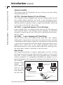
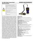
Perfusion
Fast -Step
Model SF-77B
Publication 5707-001-REV-A
WEEE/RoHS Compliance Statement
EU Directives WEEE and RoHS
To Our Valued Customers:
We are committed to being a good corporate citizen. As part of that commitment,
we strive to maintain an environmentally conscious manufacturing operation. The
European Union (EU) has enacted two Directives, the first on product recycling
(Waste Electrical and Electronic Equipment, WEEE) and the second limiting the use
of certain substances (Restriction on the use of Hazardous Substances, RoHS).
Over time, these Directives will be implemented in the national laws of each EU
Member State.
Once the final national regulations have been put into place, recycling will be offered
for our products which are within the scope of the WEEE Directive. Products falling
under the scope of the WEEE Directive available for sale after August 13, 2005 will
be identified with a “wheelie bin” symbol.
Two Categories of products covered by the WEEE Directive are currently exempt
from the RoHS Directive – Category 8, medical devices (with the exception of
implanted or infected products) and Category 9, monitoring and control instruments.
Most of our products fall into either Category 8 or 9 and are currently exempt from
the RoHS Directive. We will continue to monitor the application of the RoHS
Directive to its products and will comply with any changes as they apply.
• Do Not Dispose Product with Municipal Waste
• Special Collection/Disposal Required
Table of Contents
Warner Instruments
Perfusion Fast-Step Model SF-77B
1
SUBJECT
PAGE
Introduction ..........................................................................2-3
Front Panel Description ..........................................................4
Rear Panel Description ............................................................5
System Description..................................................................6
Set-up Procedure......................................................................7
Capillary Tubes and Holder ....................................7-8
Manifolds ....................................................................8
Mounting the Motor Assembly ..............................9-10
Loading Solutions ................................................10-11
Care And Maintenance ............................................11
Using the Controller ............................................12-13
Fast Stepping with Theta Glass ..............................13
Sample Experiment ..........................................................14-15
Specifications ....................................................................16-17
Accessory Reorders ..............................................................18
Warranty & Services ..............................................................19
www.warneronline.com
Introduction
Warner Instruments
Perfusion Fast-Step Model SF-77B
2
The SF-77B is a simple but highly effective stimulus solution delivery device
for use in a variety of patch clamp and electrophysiology studies. Control
and test solutions flow continuously through adjacent stimulus delivery
tubes and a stepper mechanism selects which tube is directed at the preparation. The rapid response and nominal hysteresis of the stepper mechanism allows for very fast switching times. Complete solution changes are
typically achieved within 20 msec for a large 700 mm step and times are
significantly shortened as the step size is decreased.
Multiple Solution Studies
In the standard configuration, up to six different solutions are connected to a single input manifold which in turn is connected to one of
three square glass stimulus ports. The three stimulus port design is
superior to a two-port design in that complex solution exchange protocols can be brought to bear on the sample under study. Since the
complete system is designed o accommodate three manifolds (one for
each stimulus port) and each manifold can accommodate up to 6 feed
lines, it is possible to immediately select between 18 different input
solutions.
•
Solution changes between stimulus ports occur within
milliseconds.
•
Changes between solutions connected to an individual port
occur within five seconds.
•
Entirely new solutions can be added into any port with a waiting time of no more than 30 seconds.
•
The cell is never required to pass through intervening solutions
to get from control to test solution.
Manual or External Control
The stepper mechanism can be manually controlled via the front panel
or externally directed from your data acquisition program. Manually,
the system can be stepped to 8 positions in 7 equally spaced steps.
These same 8 positions can also be directly selected by applying an
analog signal to the external analog input BNC or by passing a 3 byte
word to the TTL input on the instrument rear panel.
Square Glass Stimulus Ports
The square glass tubes used for solution delivery significantly reduces
mixing turbulence between solutions allowing the SF-77B to be used
for studies with both membrane patches and whole cells, even when
the cells are not fixed to a substrate.
Publication 5707-001-REV-A
www.warneronline.com
Introduction (Cont’d)
Warner Instruments
Perfusion Fast-Step Model SF-77B
3
System Versatility
The design of the SF-77B permits the use of various size glass tubing
for perfusion delivery.
SF-77B – Standard System (0.7 mm ID tubes)
The standard system is shipped with 3SG700-5 single-walled 3-barrel
glass tubing which eliminates the need to glue individual barrels
together. Spacing between barrels is 0.7 mm and step speed between
adjacent barrels is typically 20 msec. Single barrel SG800-5 tubes (up
to 5) can be used with the same holder.
SF-77BLT – Large Tube System (1.0 mm ID tubes)
Larger stimulus ports are required when using the SF-77B with larger
cell structures such as the Xenopus oocyte. Solutions are delivered
through 1.0 mm ID square tubes (SG1000-5) with barrel-to-barrel spacing of 1.4 mm.
SF-77BST – 1 msec Stepping with Theta Tubing
The SF-77B has been successfully tested using theta style capillary
tubing with a step speed of 1 msec between adjacent barrels. Standard
2 mm diameter theta tubing is pulled to a tip diameter of 300 mm with
a spacing of 100 mm between barrels. In this design, placement of the
pipette tip is critical due to the smaller perfusion stream. Since
mechanical artifacts can be evident when using these small step sizes
the motor drive voltage is adjustable at the rear panel.
Easy Set-Up
The stepper mechanism is compact, lightweight, and free of either
mechanical or electrical noise.The mechanism connects to the control
box with a 2 meter shielded cable and is provided with a mounting
rod for attachment to a manipulator. Manifolds can support 2,4 or 6
inputs depending on the experiment. Solutions flow from reservoirs to
the manifold
Solutions B1-B6
Solutions C1-C6
through PE-50 Solutions A1-A6
Approximately 30 seconds
tubing
and
PE-50 Tubings
for new solution flow when
adding new reservoirs.
PE-10 tubing is
Manifold B
Manifold C
Manifold
A
used to connect the manifold outputs to
Approximately 5 seconds
PE-10 Tubings
for new solution flow when
switching manifold input.
the glass tubes.
Glass Tubes
Step
Stimulus effect in 20 milliseconds
for 800 µm step size
Cell attached electrode
Step
Publication 5707-001-REV-A
www.warneronline.com
Front Panel Description
Warner Instruments
Perfusion Fast-Step Model SF-77B
4
E
D
A) STEPS/POSITION
A
C
B
Step length (distance between stepper positions) is selected with the
thumbwheel control. Minimum step size is 100 µm (.004 inches) with the
thumbwheel set at 1 and the maximum step is 1.5 mm (.060 inches) with
the control at 15.When using the 3 barrel glass supplied with the standard
SF-77B (p/n 3GC700-5, barrel to barrel spacing of 700 µm), the control is
set to 7 (7 x 100 µm).
B) MODE SELECT SWITCH
Control of the stepper device can be INTERNAL (manual), EXT DIGITAL or
EXT ANALOG. The 3 position toggle switch is used to select the desired
mode.
C) INTERNAL
A 5-position switch is used to manually select up to 5 positions.An LED display indicates the position selected. This same display indicates position
when control is from an external signal.
EXT DIGITAL
See rear panel description for controlling with a digital signal.
D) EXT ANALOG
An analog signal for stepper control is applied to this input. Up to 5 positions can be used. Positions correspond to the dc voltage levels as shown:
Position 0
0 volts
Position 3
3 volts
Position 1
1 volt
Position 4
4 volts
Position 2
2 volts
E) INITIALIZE
The INITIALIZE push-button is used to initialize the pipe position at the
beginning of an experiment or at any time one wishes to check or confirm
positions. This is done in the INTERNAL (manual) mode by selecting the
desired position and depressing the push-button.
Publication 5707-001-REV-A
www.warneronline.com
Rear Panel Description
H
Warner Instruments
Perfusion Fast-Step Model SF-77B
5
J
F
G
F) POWER BLOCK
This block includes the power line cord connector, ON-OFF switch and the
input power fuse.
G) MOTOR
The stepper mechanism connects to the control box here.
H) EXTERNAL DIGITAL INPUT
Digital inputs for position control connect to the 3 BNC connectors labeled
D0, D1 and D2. Up to 8 positions can be controlled when all 3 lines are
used. Digital inputs are TTL compatible and readily accept digital outputs
from computers and computer interfaces.
Positions are controlled per the table shown here.
TRUTH TABLE
Position
D0
D1
D2
0
L
L
L
1
H
L
L
2
L
H
L
3
H
H
L
4
L
L
H
5
H
L
H
6
L
H
H
7
H
H
H
J) MOTOR VOLTAGE ADJUST
This control is factory set and only used for experiments involving small
(100 µm) steps. Its use is further described in the section dealing with Fast
Stepping with Theta Tubing.
Publication 5707-001-REV-A
www.warneronline.com
System Description
Warner Instruments
Perfusion Fast-Step Model SF-77B
6
The main use of the SF-77B Perfusion Fast - Step is the rapid change of
solutions bathing a single cell or patch of membrane attached to a patch
electrode. Solution changes can be made in as little as 20-50 ms (approximately 1 ms using 2 barrel Theta tubing) and once changed the new solution with its particular concentration of pharmacological agent will remain
stable until changed again.
An important capability of this device is also that a large number of solutions can be utilized during the course of a single experiment, in spite of
the compact size of the device. This takes a bit of organizational thought
before starting the experiment, but the return is the ability to easily use 1530 different solutions in a single experiment.
This is accomplished by having as many as six solutions feeding through a
unique manifold into each of the three "pipes" in front of which the
cell may be placed. This allows any of the three pipes to have any one of 6
solutions flowing through it at any time. It is even possible, during the
course of an experiment, to change the six solutions flowing into any one
of the manifolds, allowing a virtually limitless number of solutions to be
used.
In order to fully implement this feature it is important to realize that there
are actually three time frames that need to be considered in the proper use
of the device. The first is the 50 ms or less time course for changing
between different pipes. The second is the 5 second dead time required to
change from one solution to another in the same pipe. Finally there is the
30-60 second time required to change one of the six starting solutions flowing into any of the three manifolds. The third time frame is only important
for experiments that would typically use more than 15 different solutions
in a single experiment.
Each of these uses will be explained in detail, and a "typical" experiment
will be worked through using each of these features.
Publication 5707-001-REV-A
www.warneronline.com
Set-Up Procedure
7
Warner Instruments
Perfusion Fast-Step Model SF-77B
The SF-77B Perfusion Fast - Step systems are packaged in three parts:
1) stepper motor assembly with a set of 3 manifolds*;
2) the electronic controller;
3) glass holder, the capillary tubes and polyeyhylene tubing.
* MM Series are supplied with SF-77B and SF-77BST. ML Series are supplied with SF-77BLT. Manifolds are available in 2, 4, and 6 inputs.
T h e C a p i l l a r y T u be s a n d H o l d e r
Glass Capillaries
The SF-77 B Perfusion Fast - Step makes use of square capillary
tubes for its "pipes". These facilitate placement of the tubes in the
chamber and, more importantly, reduce turbulence and provide a more
even flow of solution. The capillaries supplied with the standard
SF-77Bare 3-barrel which have an inside dimension of 0.6 mm each
barrel and a wall of 0.1 mm. The barrels have been fused together in
manufacture so no gluing is necessary.
Larger 1.0 mm tubing is supplied with system SF-77BLT and 2-barrel
Theta tubing is supplied with the SF-77BST.
Glass Holders
The appropriate glass holder is supplied with each system. The standard SF-77B holder is the GH-1. It holds the 3SG700-5 three-barrel tubing or up to 5 individual barrels of SG800-5 tubing (0.6 mm inside,
0.12 mm wall). SF-77BLT is supplied with the GH-10 holder which
holds up to 3 of the SG1000-5 glass tubes (1.0 mm inside, 0.2 mm
wall). Holder GH-2T holds the 2 mm Theta glass.
Holding the Glass
The capillaries can be mounted directly in the holder, which maintains
them in position by pressure. The 3-barrel glass is simply placed into
the holder slot and the threaded handle is tightened to hold the glass
rigid. If single tubes are used, we recommend that the capillaries be
cemented together first to insure that they are perfectly level and in
alignment. Place the capillaries on a flat surface and butt the ends
against a straight edge. Alignment is critical. We suggest you check
under a dissecting microscope. Use only a small dab of cement placed
near, but not exactly at the center line in the lengthwise direction. Do
not put the cement near either end of the tubes as capillary action will
carry it into the tubes and may clog them.
Publication 5707-001-REV-A
www.warneronline.com
Set-Up Procedure (Cont’d)
Warner Instruments
Perfusion Fast-Step Model SF-77B
8
After the cement dries (a few minutes is sufficient) simply slide the
tubes into the holder such that nearly half of the tube length extends
from the holder.
This length is adjustable depending on the dimensions of your particular set-up and chamber. Ideally, however, it is best to have the tubes
more or less centered on the holder.
The tubes and holder can be attached easily to the mounting device,
but this should be done after this device is installed, as described in
the next section.
M a n i f o l ds
Manifolds are made with 2, 4, and 6 inputs (specified at time of order). MM
Series manifolds are standard with the SF-77B and SF-77BST. ML Series are
provided with the SF-77BLT.
MM Series Manifolds
The inputs connect to PE-50 tubing which fits over the hypodermic
tubings. A length of PE-10 tubing is factory installed in the manifold
output. This tubing fits into the glass pipes and is sealed with wax.
At some time in the future, the PE-10 tubing will require replacement.
Proceed as follows:
1) Unscrew the manifold tail from the head and pull the old tubing
from the tail.
2) Cut a length of PE-10 tubing, 8 to 9 inches long.
3) You need to stretch one end of the tubing so that its diameter is
reduced sufficiently to fit into the hole in the tail piece. Do this by
gripping one end between thumb and forefinger of both hands and
pulling firmly. This may take a little practice.
4) Trim off the unstretched portion of tubing at the end so that the
smaller diameter portion can be inserted into the hole. Pull the tubing
through until the full diameter is inside the tail. Trim the tubing flush
with the tail inside end and reinstall in the head piece. Make sure the
rubber seal is inside the head before screwing the parts together.
ML Series Manifolds
These manifolds use the PE-50 tubing on both input and output. The
larger PE-50 fits nicely into the SG1000-5 glass pipes used with the
SF-77BLT.
Publication 5707-001-REV-A
www.warneronline.com
Set-Up Procedure (Cont’d)
9
Warner Instruments
Perfusion Fast-Step Model SF-77B
M o u n t i n g t h e M o t o r A s s e m bl y
The SF-77B Perfusion Fast - Step is designed to be mounted on and positioned by a manipulator. It is light enough to be attached to a micromanipulator without producing drift, but for most applications a standard
coarse manipulator will be sufficient. Ideally the device should be positioned within the set-up so that it can be easily removed from the manipulator and replaced. This will facilitate cleaning and loading the device.
Positioning the angle of the motor assembly is made by loosening the black
wing nut. When loosened, the motor mount bracket and manifold bar can
be rotated to accomodate the setup. Additionally, the angle of the motor
extension bar (white plastic bar attached to the motor drive) can be adjusted by rotating the motor collar (black block mounted on the motor). Before
rotating the block, loosen the small set screw with the Allen wrench supplied with the SF-77B motor assembly. Retighten the screw lightly once the
desired position is attained.
NOTE: Do not overtighten this screw. Motor operation may be
adversely effected.
A subsection of this part of the device is the assembly of tubing etc. that
will feed solutions into the manifolds and then to the pipes. Most
simply, the feeder arrangement consists of up to 18 syringes with luer stopcocks (ideally 2-way to minimize; three-way can be used, however this
tends to introduce air bubbles at the point of entry into the PE-50 tubing.
Be careful to avoid air bubbles, as once in the PE-tubing, the flow of
solution is inhibited. Depending on the rate of flow used for a particular
application, this may not be detected immediately. Avoidance and
removal of bubbles will be discussed later). The syringes are mounted in a
rack, loading end up, and placed approximately 1 meter above the surface
on which the chamber is fastened (usually the microscope stage). The
height above the device will depend on the experimental design, for example, perfusing an inside out patch will require a slower flow rate than perfusing a cell. The syringes can be mounted either inside or outside of the
Faraday cage if one is being used. A distinct advantage to this system is that
electrical noise is not a problem, even for single channel recording.
Syringes of 20 or 60 ml volume are recommended, although other
containers such as seperatory funnels or bottles can be used. The main
advantage of syringes is their economy and disposability. For expensive reagents smaller syringes can be used. With careful preparation of the
Publication 5707-001-REV-A
www.warneronline.com
Set-Up Procedure (Cont’d)
Warner Instruments
Perfusion Fast-Step Model SF-77B
10
solution feeder lines, the SF-77B Perfusion Fast - Step can be reliably used
with less than 1 ml of solution in the reservoir and with less than 0.5 ml to
prime the line (depending on distance of solution reservoir from the microscope stage).
L o a di n g S o l u t i o n s
It is recommended that one of the solutions in each of the three pipes
should be the control buffer bathing the cells or patches. This solution can
be used as a rinsing solution between applications.
Solutions are poured into the syringes with the luer stopcock set
to the closed position. A useful method for the removal of air bubbles is as
follows. Remove the tip of a cotton tipped applicator and pack into the
needle, this acts as a bubble trap. Even with careful removal of air bubbles
prior to the solution reaching the PE-tubing, occasionally small bubbles will
form. The cotton tip breaks up the bubble, then the smaller ones formed
can be easily tapped out. To prevent bubble formation in the bulk of the
solution, always pre-warm solutions.
This entire procedure is made much easier by removing the manifold from
the holding bar and unscrewing the tail portion of the manifold, that is the
section of the manifold through which solutions flow out and into the capillary. Because the output tubing is so much smaller than the input tubes
the resistance is considerable and this can cause solution to back up into
neighboring tubes during the filling procedure. Without the output
section of the manifold this does not occur. After all the lines are filled the
manifold can be screwed together again and mounted back in the holder.
Next, remove the needle from the syringe. Hold the needle about 1-2 mm
below the syringe, then open the luer valve. Solution will flow under the
force of gravity, without the requirement for additional force, for example
by plunging the syringe. As soon as the solution reaches the end,
allow a small drop of solution to enter the needle. When the cotton is wet,
quickly insert the needle on the syringe. Observe the solution passing
along the PE-50 tubing, then after making sure that there are no columns of
air in the tubing, switch the luer valve to closed. Inspect the needle to see
if any air bubbles are present, tap the needle to dislodge. Often large bubbles will form at the junction of the syringe and the luer valve, these can be
easily removed by tapping. If this will not suffice, then insert a long needle
into the solution and draw out the air bubble (care must be taken not to
cross contaminate). If at this point even a small bubble remains, tap the
syringe and dislodge. This can be rather time consuming, depending on the
number of solutions to be used, but is a very useful exercise that will maximise the performance of the SF-77 Perfusion Fast - Step.
Publication 5707-001-REV-A
www.warneronline.com
Set-Up Procedure (Cont’d)
Perfusion Fast-Step Model SF-77B
Next attach the PE-50 tubing to the mainfold. Open the luer valve and
allow solution to flow through the glass ‘pipes’. If at this point there is inhibition of solution flow into the glass ‘pipe’, turn the luer valve to closed and
remove the outflowing section of the mainfold. Insert into a piece of tygon
tubing (I.D. 1/16, O.D. 1/8 Wall 1/32) attached to a syringe, and simply aspirate and eject air. Re-attach the manifold and open the luer valve. If there
is no solution flow at this point apply positive pressure to the reservoir
syringe (making sure all other feeder lines are closed otherwise backflow will occur. The luer valve should be briefly re-opened to be sure
that solution is indeed flowing through the line. The same procedure is
repeated for each solution in turn. After all six solutions have been readied
in this way it is advisable to turn on the buffer solution line so as to clean
the capillary pipe of any residual solutions.
Warner Instruments
11
The same procedure should be repeated for each of the three capillary
pipes. When completed all the solutions to be used in the experiment are
at the manifold so that simply turning a stopcock to the on position will
allow that solution to flow from the manifold to the capillary tube. This
should require less than 2 seconds, but 5 seconds are recommended to be
sure that the last solutions have been completely washed out. Although in
general there is no leakage from the end of the pipes we recommend that
at the start of an experiment all three pipes have buffer flowing through
them (see sample Experiment below).
If a line is not to be used (i.e. if less than six solutions are to be used in any
one pipe) then it is necessary to use a "plug" for that line on the manifold.
This is to prevent solution from "backing up" into an open line.
Alternatively all unused lines can simply be loaded with buffer solution,
however this is more time consuming.
NOTE: It is best to keep the output ends of the pipes submerged
in solution or water when changing the setup. If the pipes are
left unsubmerged for any length of time, fluid will weep from
the tubings and air bubbles will creep in.
Ca r e a n d M a i n t e n a n c e
At the end of each experiment, allow all solutions to flow out of the reservoir and add a few ml of 70% ethanol. The manifold is composed of delrin
and stainless steel and PE-tubing is unaffected by ethanol, thus this cleaning
procedure can be withstood. Next flush all the lines with water. After all
solutions have run through, remove the needle and dispose of the cotton
tip (prevent cross contamination of solutions). Finally air dry (pressurized)
solution lines.
Publication 5707-001-REV-A
www.warneronline.com
Set-Up Procedure (Cont’d)
12
Warner Instruments
Perfusion Fast-Step Model SF-77B
U s i n g t h e Co n t r o l l e r
Control of the SF-77B Perfusion Fast - Step has been designed to be
as simple as possible. The device can be controlled manually or by electronic signals generated by a computer or stimulator. The three main
parameters under the investigators control are position, step size and duration. Position tells the device which capillary pipe to position in front of
the target cell or membrane patch. Step size, adjustable from 0.1mm to
1.5mm in 0.1mm steps, is selected for the center to center distance of the
pipes. Duration determines the length of time that the capillary pipes
remain in a given position.
Position. There are five available positions in INTERNAL (manual) and EXT
ANALOG modes and eight positions in the EXT DIGITAL mode. The typical
use is with 3 pipes and only three positions are required. Position is selected by manual switch position or by an external analog or digital signal.The
position selected is displayed on the LED readout.
Analog Voltage Control
When using an analog input, the positions are voltage sensitive. Zero
volts corresponds to 0 position and stepping the voltage in 1 volt
increments steps the device (2 volts = position 2, etc.).
Digital Control
The rear panel has 3 BNC inputs to accept standard TTL compatible
signals for digital control from a computer or other digital signal
source. The 3 inputs allow for as many as 8 positions to be controlled.
See REAR PANEL DESCRIPTION (section 2.0) for more detail.
Step Size. The distance traveled is adjusted with the counter control
(steps/position). Minimum step is 0.1mm (1 step) and maximum is
1.5mm (15 steps). For the standard 3SG700-5 capillary pipes supplied
(barrel to barel spacing 0.7 mm), a step length of 7 is required to move
from center to center. This adjustment should, however, be made
empirically for each new set of capillary pipes.
Duration. When driven with an analog signal, the time spent in a position is determined simply by how long the voltage corresponding to
that position lasts. To move from pipe 0 to pipe 1 for 1 second and
then return to pipe 0 requires a voltage step of from 0 to 1 V that lasts
1 second and then returns to 0 V. I
If a digital signal is the external control, the stepper will stay in a position until it receives the next command. In the absence of a signal, the
motor will go to the “0” position.
Manually, the position is maintained until changed to another switch
position.
Publication 5707-001-REV-A
www.warneronline.com
Set-Up Procedure (Cont’d)
Warner Instruments
Perfusion Fast-Step Model SF-77B
13
Initializing the Position
Before beginning any experiment it is required to initialize the pipe
position by pressing the "Initialize" button. The stepper motor will
move to whichever position is manually selected. This brings the
pipes into a known position from which all other positions are referenced. For a setup with 3 pipes, initialize in the center position "2".
Readjust the flexture spring holder to correct the alignment if necessary (loosen the collar set screw and move the collar to align the flexture spring to its neutral unflexed position).
External Control - If the initialization is performed when there is 0
volts on the input line then the pipes will automatically assume the 0
position. If there is another voltage on the line then the pipes will go
to that position immediately, and automatically, after the initialization.
If at any time during an experiment or series of experiments the positions become confused then simply pushing the initialize button will
bring everything back into register.
F a s t S t e pp i n g w i t h T h e t a G l a s s
Very fast perfusion stepping is possible using 2 barrel Theta tubing. The
technique requires close attention to detail and careful placing of the pipes
and the excised patch. The following is information provided as a general
guide.
Preparation of the Theta Glass
The tubing is pulled on a standard puller for a tip diameter of approximately 300 µm and a barrel to barrel spacing of approximately
100 µm.
Motor Voltage Adjustment
When using 100 µm steps, it is important to minimize any vibration
produced by the stepper motor. This is accomplished by reducing the
motor voltage with the control located on the rear panel.
The voltage is lowered until the vibration artifact is minimized. Any
residual artifact may be removed by subtracting averaged null traces.
Reference:
Jie Zheng and Fred Sigworth, Selecting Changes during Activation of Mutant
Shaker Potassium Channels, J. General Physiology, vol.10 August 1997,
101-117 Rockefeller Univ. Press
Publication 5707-001-REV-A
www.warneronline.com
Sample Experiment
Warner Instruments
Perfusion Fast-Step Model SF-77B
14
As an example of the use of this stimulating system we may take an experiment in which the activity of several adrenergic agonists and antagonists
are investigated for their ability to modulate a K-current in Pancreatic islet
ß cells.
Prior to beginning the experiment the reservoirs feeding the three pipes
(we will call them 0, 1 and 2) are mounted approximately 1 meter above
the microscope stage. They do not have to be placed inside the Faraday
cage. For each pipe one of the six lines will contain physiological buffer,
i.e. the control bathing solution. Pipe 0 will also have an adrenergic agonist, clonidine, at 5 concentrations from 1 nM to 1 µM. Pipe 2 will have the
antagonist yohimbine, also at 5 concentrations. Pipe 1 will have
epinephrine at 5 concentrations. Thus each pipe has buffer and either an
agonist or antagonist at 5 different concentrations.
After each of the solutions is brought into the manifold and through the
pipes, the buffer is turned on in each pipe to completely wash away the
other solutions. Thus at the beginning of the experiment each of three
pipes has only buffer in it. All solutions are turned off so that nothing is
leaking from the pipes. Finally the position of the pipes is initialized.
After a cell is chosen and the whole cell patch clamp configuration
obtained the stimulating apparatus is lowered into the dish, and under low
power is manipulated into the region of the cell. Depending on the preparation the cell may either remain attached to the dish substrate or may be
suspended above the floor of the dish on the tip of the electrode. In either
case the pipes are manipulated into a position in which the cell is directly
opposite the lumen of pipe 0. Buffer is turned on in all three pipes so that
the cell is now in a flowing solution of control physiological buffer. A series
of 5 membrane voltage pulses each lasting 50 ms are delivered to determine the magnitude of the K-current under control conditions.
Following this, the solution in pipe 1 is switched to the lowest concentration of epinephrine. A stimulating protocol in which the cell is moved to
pipe 1 (by delivering a 1 volt step from the analog output) immediately
after which a series of membrane voltage steps lasting 50 ms each are delivered, and then the cell is returned to pipe 0 (by changing to 0 volts from
the output). The duration of the step is 300 ms (5 x 50 ms, with a 10 ms
delay between each membrane voltage step). The data are saved and the
solution in pipe 0 is changed to the next highest concentration of epinephrine by turning one luer stopcock to the off position and the next one
to the on position. 5 seconds later the same protocol can be repeated, now
examining the effect of the higher concentration of epinephrine on the Kcurrent elicited by voltage.
After the series of 5 concentrations of epinephrine are completed the pipes
are shifted so that the cell is now in the lumen of Pipe 1, which has
Publication 5707-001-REV-A
www.warneronline.com
Sample Experiment (Cont’d)
Warner Instruments
Perfusion Fast-Step Model SF-77B
15
been changed to buffer. This is accomplished by having 1 volt appear on
the output. The same experiment can now be repeated with different concentrations of clonidine as the pipes are moved so that the cell goes from
pipe 1 to pipe 0. The only change in the stimulus protocol is that the voltage output goes from 1 to 0 and back to 1 for each test series.
Upon completion of the agonist series the antagonist effects can be tested.
First the lowest concentration of Yohimbine is turned on in pipe 2 and the
cell is moved to that pipe (i.e. the pipes are shifted so that the cell is in front
of this pipe). An effective concentration of epinephrine (determined from
the earlier run) is now turned on in pipe 1. For this experiment the cell is
shifted from pipe 2 to pipe 1, but possibly for only a single 50 ms voltage
pulse so that the antagonist cannot be competed off by the agonist. Thus
the protocol is for the analog output to go from 2 volts to 1 volt and back
to 2 volts in about 90 ms. Once in the agonist solution (change time is
about 30 ms) the voltage pulse is delivered to evoke the K-current, and the
cell is immediately moved back to pipe 2. This can be repeated for the 5
concentrations of antagonist available to pipe 2.
For this experiment all of the protocols could have been written previously, requiring only a new protocol to be brought up, one or two luer stopcocks to be turned on or off and a button to be pushed activating the computer acquisition. The total estimated time of such an experiment could be
as little as 4-5 minutes.
In the course of this relatively straightforward experiment 15 concentrations of 3 pharmacological agents have been tested for their effects on the
K-current. These data should provide relatively complete dose response
data for these three agents, and by the simple process of changing the duration of the steps into the stimulus solutions (by simply lengthening the voltage output) kinetic data could also be obtained. If the effective concentrations for these drugs had already been known a smaller range of concentrations could have been used and additional drugs included in the experiment. New reservoirs could also be installed with new drugs, extending
the time of the experiment only an additional 10 or so minutes.
More complex stimulus protocols are also possible in which there are several shifts of the pipes during the course of a single test. Thus it would be
possible to go from pipe 0 to pipe 1 for a period of time and then to pipe
2, returning either to pipe 1 or pipe 0. The stay in each pipe is independently variable. It is also important to note that, in the case of electrophysiological experiments, membrane potential may be varied independently of
the pipe movement.Thus this simple arrangement allows the experimenter
the flexibility to build quite complex stimulus parameters.
Publication 5707-001-REV-A
www.warneronline.com
Specifications
Warner Instruments
Perfusion Fast-Step Model SF-77B
16
Specifications
Number of Steps:
1 to 7 (2 to 8 positions)
Step Size:
Adjustable from 100 µ m to 1.5 mm in 100 µ m
increments, with STEPS/POSITION switch
Step Speed:
Typically 20 msec for a 700 µ m step
Step Control:
Manual:
8 position with POSITION selector
Analog Signal:
5 positions with voltage levels 0-4 Volts, 1V/step
Digital Signal:
Maximum Stepped
Range:
8 positions with 3 byte TTL signal
12.5 mm
Mounting Handle:
6.3 mm dia. X 10 cm long
Stepper Weight:
(including handle)
110.5 grams
Solution Manifolds
Three manifolds are supplied with each system; MM series for SF-77B and SF-77BST
and ML series with SF-77BLT. Manifolds have 2,4 or 6 inputs. Specify your choice
when ordering.
MM Series:
MM-2, MM-4 and MM-6 manifolds use PE-50 tubing at the
input and PE-10 tubing at output
ML Series:
ML-2, ML-4 and ML-6 manifolds use PE-50 tubing at both
input and output
Solution Flow Rates
With MM Series:
100 µ l/min
With ML Series:
1 ml/min
Rates are measured with a solution reservoir height of approximately 60 cm
(24 inches).
Control Box
Size:
6.3 cm H x 14 cm W x 23 cm D
Power Requirements: 100-130 or 220-250 VAC, 50/60 Hz, 10 VA
System Shipping
Weight:
2.7 kg
Warranty:
2 years, parts and labor
Publication 5707-001-REV-A
www.warneronline.com
Specifications (Cont’d)
Glass Tubes (end views)
SG800-5
3SG700-5
SG1000-5
TGC200-10
.84
1.4
1.4
.6
1.0
2
2.5
.7
ALL DIMENSIONS IN MILLIMETERS
Warner Instruments
Perfusion Fast-Step Model SF-77B
17
Publication 5707-001-REV-A
www.warneronline.com
Accessory Reorders
Warner Instruments
Perfusion Fast-Step Model SF-77B
18
Business hours are 8:30 AM to 5:00 PM (eastern time), Monday to Friday.
Telephone: 800-599-4203 Fax: 203-776-1278
The following accessories are available from stock:
Order No.
Description
Pkg. Qty.
64-0200
Manifold, 2 to 1
1
64-0201
Manifold, 4 to 1
1
64-0202
Manifold, 6 to 1
1
64-0203
Manifold, 2 to 1
1
64-0204
Manifold, 4 to 1
1
64-0205
Manifold, 6 to 1
1
64-0750
Polyethylene Tubing
10’
64-0752
Polyethylene Tubing
10’
64-0119
3-Barrel Square Glass Tubes, 0.6 mm ID,
5 cm long
10
64-0120
3-Barrel Square Glass Tubes, 0.6 mm ID,
10 cm long
10
64-0121
Single Barrel Square Glass Tubes, 0.6 mm ID,
0.84 mm OD, 5 cm long
25
64-0122
Single Barrel Square Glass Tubes, 1 mm ID,
1.4 mm OD, 5 cm long
25
64-0811
Theta Glass Tubes, 2.0 mm OD, 10 cm long
100
64-0124
Glass Holder for 3SG700-5 or SG800-5 Glass
1
64-0125
Glass Holder for 2 mm Theta Glass
1
64-0126
Glass Holder for SG1000-5 Glass
1
Other sizes of square glass tubing are available from:
Vitrocom, Inc.
Mountain Lakes, New Jersey 07046
Telephone: 201-402-1443.
Publication 5707-001-REV-A
www.warneronline.com
Warranty & Services
Please direct your questions regarding service or repairs to our engineering
department at 800-599-4203.
Warner Instrument Corp. warrants the model SF-77B Perfusion Fast-Step
system to be free from defects in materials and workmanship for a period
of 2 years from date of shipment. If a failure occurs within this period, we
will either repair or replace, at our option, the faulty component(s).
Warner Instruments
Perfusion Fast-Step Model SF-77B
19
Publication 5707-001-REV-A
www.warneronline.com