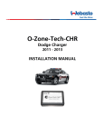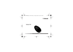
1
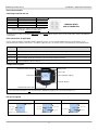
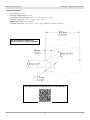
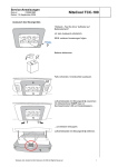
SmarTemp Control fx 2.0
Digital Timer Interface
Installation / Operation Instructions
General
Thank you for choosing Webasto to meet your heating needs. The Webasto SmarTemp Control fx 2.0 enables you to
preset start-up cycles of your Webasto heater 7 days a week with 4 individual times each day.
Operation
The Webasto SmarTemp Control fx 2.0 is controlled using a rotary dial around the outside of the unit to scroll
through menu options. Simply click the selection button ( ) to make your choice. The following sections will define
each menu item and its default setting.
Compatibility
All Coolant Heaters; the SmarTemp Control fx 2.0 has an output of 1A for the heaters ON/OFF signal. Heaters
requiring a higher amperage signal will require a relay to accommodate different specifications. See electrical
connections for details. Note: Relay not included.
Mounting Procedure
1. Find a suitable mounting location (on a flat surface if possible) in a visible area.
CAUTION: Always install in an area protected from the effects of weather
and contamination.
2. Use the drilling dimensions to lightly mark the two mounting holes.
3. (Optional Step) To route wire harness through the mounting surface,
drill a 17mm hole as notated on the drilling dimensions image.
NOTE: Always make sure there are no obstacles behind the mounting
location prior to drilling.
4. Secure the Webasto SmarTemp Control fx 2.0 using the two supplied #4
screws.
5. Apply the supplied “Heater Off” warning sticker in a highly visible
location to the driver’s area. Refer to the example sticker below.
6. Observe the Menu Descriptions section for proper menu setup.
1
SmarTemp Control fx 2.0
Installation – Operation Instructions
Electrical Connections
SmarTemp Connector Pin-out
Pin Number Description
Wire Color
1
+12 / 24V
Red
2
GND
Brown
3
Heater Output
Black
4
Green
*Diagnostic Blink Code
For terminal removal use: Molex terminal removal tool
P/N: 11-03-0044 (http://www.molex.com)
TERMINAL INSERT
SIDE OF CONNECTOR
*Diagnostic Blink Code functionality does not apply to most coolant heaters. Refer to the Error Code section for additional
information.
Relay Connection: (If applicable)
Heaters requiring higher amperage ON/OFF signal will require a relay to accommodate different specifications. If the
connected heater requires more than a 1A ON/OFF signal to start, use the pin-out of a standard relay as described below.
Relay
Output
Relay Pin 30
Battery (B+) power source (Fused according to required heater amperage)
Relay Pin 85
Ground
Relay Pin 86
Heater ON/OFF signal wire from pin 3 of SmarTemp Control fx harness.
Relay Pin 87
Switched ON/OFF signal to heater.
Component Description
(Webasto) ON/Off Button
Rotary Knob
Screw Cap
Status Indicator Light(s)
LCD Screen
Selection Button
*Micro USB Service Port
* The micro USB service port is not used for heater diagnostic purposes on SmarTemp Control fx 2.0.
LCD Screen Legend
Mode (Auto or Manual)
Auto Mode
Current Day
Current Day
Day and Time
Timer Active
Auto or Manual
Mode
Auto Mode
NOTE: When Auto is visible, timers are enabled
Manual Mode
Current Day
Current Time
Heater ON
Runtime Remaining
2
Current Time
Manual Mode
Heater ON
Runtime Remaining
SmarTemp Control fx 2.0
Installation – Operation Instructions
Menu Descriptions
Mode
Definitions
Default
Two modes are possible:
Manual
–
Auto mode enables the pre-defined timer programs. Manual ON/OFF
functionality is still possible while in this mode.
– Manual Mode allows the heater to be operated via the Webasto button on the
SmarTemp Control fx 2.0. While in Manual Mode, all Auto Mode functionality is
permanently disabled.
Note: While in manual mode the heater will continue to operate based on the predefined “Duration” set by the user. See “Duration” for further detail.
Language
Language changes between English, French, and Spanish
Duration
Duration allows user to select the heater runtime of the heater. Set range is between
10 – 120 minutes selectable by 10 minute increments.
English
60 minutes
Note: Duration time for all timers will default to the set duration time. User will have
the ability to manually change duration for each timer.
Error Code
This section will log the last 5 error codes and the date that it was set. Highlight and
select an error code for a full description.
No Errors
If the heater produces an error code, the status indicator lights will flash red and the
error will display on the main screen. Error codes cannot be reset through the
Webasto SmarTemp Control fx 2.0 on the heater, a Webasto PC Diagnostics tool
needed. Refer to the heater service manual for resetting an error code.
Note: Diagnostics via blink code is not available on all coolant heaters. Error Codes
on products with no blink code functionality can still be obtained using the PC
Diagnostics test tool. Refer to the applicable service manual by visiting
www.techwebasto.com for detailed PC diagnostics information.
Options
Advanced Level adjustment; see below
Timer &
Date
Time & Date allows user to properly set the current date and time. User also has the
ability to switch between AM/PM and 24 hour format. If the 24 hour format is
selected the date format will change to dd/mm/yyyy. Use the rotary knob to choose
the time / date and the selection button to confirm each entry. The Webasto button
can be used to go back to the previous field if additional changes are needed.
Timer
There are 4 heater start-up cycles possible 7 days per week. The timer is separated into to three
categories. The user can select “Mon-Fri”, set each specific timer (T1 – T4) for a typical work week
all at once. A weekend “Sat-Sun” can be scheduled in the same manner or a full week by using the
“Mon-Sun” selection. The “custom” link allows the user to set a specific timer (T1 – T4) for each
individual day.
AM/PM
mm/dd/yyyy
When selecting a specific timer a sub-menu will appear (Edit, Skip, and Off). To change the timer
cycle, select “edit”. Changes are saved immediately. The “skip” feature allows a timer cycle to be
skipped one time within a 7 day period. Timer will reactivate after this one-time skip cycle.
Note: To turn a specific timer off permanently select “off”.
3
SmarTemp Control fx 2.0
Installation – Operation Instructions
Definitions
LVD
Default
LVD “Low Voltage Disconnect” allows the user to adjust the battery voltage level at
which the Webasto SmarTemp Control fx 2.0 will shut the heater off. A warning (LED
and message) will appear after 8 minutes of low voltage. The warning will remain on
for 2 minutes before the heater is shut off.
If battery voltage is equal to or less than the threshold selected +0.1v, the heater will
not start. i.e. if an 11.5v threshold is selected the heater cannot be started until B+ has
reached 11.7v.
12 volt - Range between 11v – 12.5v | 24 volt - Range between 21v – 25.5v
Default
Default allows the user to perform a reset to all default values.
11.4v |
24.2v
N/A
Note: A power loss will not reset user programmed values.
Password
A password can be set to prevent access to the advanced “Options” menu. Enter a 4
digit code passcode to begin securing the Options menu. Note: This is typically used in
fleet vehicle applications.
OFF
Hour
Meter
The hour meter logs the operating hours of an active ON signal to the heater. This
does not reflect the true runtime of the heater itself.
N/A
Note: For warranty purposes a diagnostic printout is still required where applicable.
This hour meter is for reference only!
SW
Version
This displays the firmware version of the Webasto SmarTemp Control fx 2.0.
Back
Select this to return to the previous screen.
Installed
Version
N/A
IMPORTANT - The Red status indicators (heater "ON") and LCD screen backlight turn off after 30 seconds. A
touch of any button or a turn of the rotary knob will re-activate these lights. If the "Webasto" button is used to reactivate these lights, an additional press of this button is necessary to turn the heater off. Note that when the
heater is "ON" the display is active.
4
SmarTemp Control fx 2.0
Installation – Operation Instructions
Technical Information
-
Rated Voltage: 12 / 24V
Operating Voltage Range: 9V - 32V
Low Voltage Disconnect Range: 12V: 11 – 12.5V | 24V: 21 – 25.5V
Operating Temperature: - 40° ... +185 °F (- 40° ... +85 °C)
NOTE: Display visible to -22°F (-30°C)
Installation Dimensions: (L x H x D) 2.7” x 2.2” x .60” (69.4mm x 55.5mm x 15.2mm)
Use this drawing for dimensional
reference only! This is NOT a Template!
For a Spanish version of this document, scan this QR Code.
5
SmarTemp Control fx
Installation – Operation Instructions
Notes:
6
SmarTemp Control fx
Installation – Operation Instructions
Notes:
7
Webasto Thermo & Comfort N.A., Inc.
15083 North Road
Fenton, MI 48430 USA
Phone:
810-593-6000
Fax:
810-593-6001
Email:
[email protected]
http://www.webasto.us
Internet:
http://www.techwebasto.com
Org. 3/2015 Rev. N/A Ver. 1.0