1
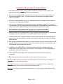
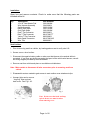
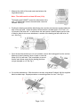
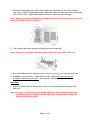
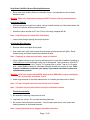
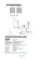
Presents
CARBONTECH™ Seat Heater
INSTALLATION INSTRUCTIONS
AND
OWNER’S MANUAL
SINGLE SEAT APPLICATION
With two 12” x 26” Heating Pads
(HI/LO/OFF Round illuminated Switch)
P/N 300202-MWA
Installation Preparation & General Notes:
1. Seat heater system will NOT work on seats manufactured using the “foam in place” (trim
cover glued to foam pad) method of trim cover attachment.
2. If the vehicle is equipped with an anti-theft radio, the radio code must be written down prior
to disconnecting battery cable. The code must be re-entered when the negative battery
cable is re-installed.
3. If vehicle is equipped with an air bag, it is advisable to disconnect negative battery cable for
3 minutes prior to beginning installation.
4. Only use parts and components supplied in kit for the seat heater installation. The supplied
components are carefully selected for optimal performance. Foreign parts may lead to problems
which could result in potential damage to the seat heater components or vehicle.
5. The installation of the heating pads must be free of creases and wrinkles.
6. Seats in vehicles with pre-loaded (power charge equipped) safety belts must be removed and
re-installed under strict adherence to the vehicle manufacturers instructions.
7. In cases where a seat is equipped with an occupant pressure sensor for air bag deployment;
please refer to the manufacturer’s manual for any specific instruction with regard to installing
seat heater kits.
8. After installing seat heater wire harness, care must be taken to ensure all seat motions are still
possible without obstruction and the moving of the seat does not cause any interference that
could damage the seat heater wire harness.
9. Installation of a CARBONTECH™ seat heater system with seats containing seam lines
running front to rear (length wise) is not permitted. Only exception is if the heating pads are
not directly located over the groove/s.
10. The overall side to side (width) of the heating pads must not be altered (cutting not
permitted).
11. Both heating pads must be connected to ensure system functions properly.
Warning: Metal, electrical conductors or hog rings are not to be placed on, through or
across the heating element.
Warning: Do not tap or solder seat heater harness to any airbag circuits. Yellow tape,
tubing and connectors will indicate airbag circuits.
Warning: Do not tap or solder seat heater harness to any pre-loaded safety belt circuits.
Page 3 of 20
Installation:
Open box and remove contents. Check to make sure that the following parts are
included within kit:
Qty
Description
Part Number
2
1
1
4
4
1
1
1
2
10
12”x 26” Seat Heater Pad
Wire Harness Assembly
Switch Assembly
Black Tape Strips
Gold Tape Strips
Red T-Tap Connector
Blue T-Tap Connector
Yellow T-Tap Connector
Male Spade Connector
Wire Ties
30-0108-MW
30-4200004
30-0213-MW
30-0110-MW
30-0109-MW
88-2300003
88-167000-TT
88-2300002
88-167000-MS
88-8880001
Seat Cushion:
1. Prior to removing seat from vehicle, lay heating pads on seat to verify size & fit.
2. Secure car on a level surface.
3. Disconnect the negative battery cable or make sure that the area to be worked within is
grounded. If you have any doubt concerning the layout of the vehicle wire harness, consult
the wiring diagram provided by the manufacturer.
4. Remove seat from vehicle and place on a suitable work table/area.
Note: Make certain to disconnect all wire connectors prior to removing seat from
vehicle.
5. Disassemble seat as needed to gain access to seat cushion cover attachment clips.
6. Unsnap j-clips and or remove
“hog ring” clips and peel
back cover. See Fig 1 & 2
Fig 1
Fig 2
Note: If trim cover has hook and loop
style tie down, care must be taken
when removing cover.
Page 4 of 20
7. Measure the width of the center seat area between the
longitudinal seams.
Note: The width must be at least 250 mm (10 in).
The heating pad CANNOT contact the side seams of the
seat. If it does make contact, the seat heater cannot be
installed. See Fig 3
Fig 3
8. Position the heating pad with the label facing down and the wire harness routed towards the
back of the seat area. Adjust the pad so the thermostat is located approx. 25-50 mm (1-2
in) forward of the back rest. In cases where the seat cushion contains lateral grooves (side
to side) to allow for trim cover attachment, a section of the heating pad will need to be cut
out. See Fig 4
Fig 4
9. Once the area that needs to be cut out is marked, remove the heating pad from the cushion.
Measure in board (towards Center of pad) on each side
40mm (9/16 in) and mark. This is necessary to ensure
that the main power supply for the heating pad does
not get damaged or cut. See Fig 5
Fig 5
10. Cut out the marked area. With the section removed, wrap lateral "bridges" with the supplied
black insulation tape. Repeat procedure on remaining sides of cut out. See Fig 6
Fig 6
Page 5 of 20
11. Reposition heating pad onto cushion foam. Make sure thermostat is in the correct location.
(see step 9) Using the supplied gold double sided tape, attach the back edge of the heating pad
to the cushion foam. With the pad attached at the rear, determine the final length.
Note: Make sure that the length difference between the cushion pad and back rest pad is not
more than 275 mm (10-3/4 in). See Fig 7
Fig 7
12. Trim if needed and attach using the supplied gold double sided tape.
Note: Seat heater pad should reach the forward edge of the seat cushion. See Fig 8
Fig 8
13. Route the heating pad wire harness so that it exits the trim cover in an inconspicuous area.
14. Installation is now complete. Double check to make sure the pad does not have any
wrinkles or is folded over onto itself. Once checked, carefully re-attach trim cover.
Back Rest:
1. Follow the same order and procedures for steps 5-13 for installing the heating pad to the
back rest.
Note: For step 11, use 2 pieces of gold double sided tape. One at the top and the other
approximately half way down to ensure the pad will not loosen and wrinkle over
time due to effects of gravity.
Page 6 of 20
Seat Heater Pad Wire Harness Routing/Attachment:
1. Route wires from cushion & back to underside of seat. Use supplied wire ties to fasten
harness to seat.
Warning: Make sure attachment locations will NOT interfere with any seat movement.
Seat Heater Switch:
1. With the seat still removed from vehicle, choose a switch location on a flat surface where the
wires won’t interfere with any seat movement.
2. Mark the location and drill a 19.5 mm (3/4 in) hole using a stepped drill bit.
Note: hand filing may be required for final fitment.
3. Insert switch through opening and snap into place.
Seat Heater Wire Harness:
1. Remove vehicle scuff plate & kick panel.
2. Start under seat, route main harness through carpet opening toward scuff plate. Route
harness along scuff plate towards the underside of dash.
Note: If opening in carpet does not exist, create as required.
3. Using a digital volt/ohm meter, locate a switched ignition circuit that is capable of handling a
10A continuous current and attach using one of the supplied T-tap connectors. Use Red Ttap for 18-22 gauge wire, blue T-tap for 16-14 gauge wire or yellow T-tap for 12-10 gauge
wire. Attach spade connector to seat heater harness red wire and connect to t-tap. Note:
Improper installation could drain your battery if you attach seat heater harness to a
constant battery source.
Warning: Never use engine control/ECM, safety device, ABS/ARS or engine cooling fan,
etc. to power the seat heater circuit.
4. Attach ring connector on the black harness wire to a suitable ground source at vehicle.
Note: A T-tap and spade connector can also be used if needed.
Note: Tap/splice into only one vehicle circuit per seat heater harness.
Final Seat Assembly:
1. Re-assemble remaining components of seat.
2. Load seat into vehicle. Do not install mounting fasteners.
3. Re-connect vehicle harness connectors. Connect seat heater switch, main power and
heating elements to seat heater harness.
Note: Heating elements can be plugged into either connector.
Page 7 of 20
4. Install seat mounting fasteners and torque to manufacturers recommended specifications.
5. Re-connect the negative battery cable and test function the seat heater system.
6. Re-check all systems and accessories where components were removed or relocated during
the installation process.
7. Re-install vehicle scuff plate and kick panel.
Page 8 of 20
Troubleshooting:
If system does not heat up or no indication of power.
-
Check fuse in seat heater harness and vehicle.
-
Temperature of seat may be above the preset thermostat temperature and will not allow
it to come on. (i.e.: sun shining on seat)
-
If the light on the heated seat switch does not come on, it could be that the switch bulb is
burnt out (replace switch) or that there is no power to the switch.
-
Ensure that all connectors are properly connected and that the ground wire is properly
grounded. (see Fig 9 for wiring diagram)
-
Using a digital ohm meter, test only the heating elements (switch not included) from the
under seat wire connector. If no resistance is found, then an open condition exists.
-
Check internal wire connectors for an open circuit. If a heating element has an open,
install a new heating element.
-
If the heating elements and seat harness tests OK, then a power supply problem exists.
-
Using a digital volt meter, start at the source and trace back through all the connectors
and switch to determine where the power loss is occurring. Repair as necessary.
-
If the seat heater fuse continues to blow, then a short or bad ground condition exists in
the power circuit.
-
If the vehicle fuse which has the heated seat T-tap connected to it continues to blow,
then the tap will need to be moved to another vehicle circuit.
Page 9 of 20
Seat Heater System Wiring Schematic:
Heater Element
Cushion
Heater Element
Back Rest
Connectors
2-Pin / White
Relay
Switch
Connector
4-Pin / White
10A Fuse
Fig 9
CARBONTECH™ Seat Heater Specification
Heater Pads:
Size
Thickness
Heating Power
Total Heating Power
Electrical Resistance
Electrical Current
Thermostat
Wire Length
Connector
Burn Rate
Specification
Weight
Content per Kit
Switched Ignition
Source
Ground
(290mm)
645 x 290mm
1.3mm
0.050 Watt/sq. cm @ 13.8 Volts
71 Watts @ 13.8 Volts
2.67 Ohm +/- 10%
5.17 Amps @ 13.8 Volts
Bi-Metal switch: on at 40°C, cuts off
at 70°C
520mm +/- 10mm
Tyco/AMP
<80mm/min. to FMVSS 302
2000/53/EG
0.094 kg
2
Note: All data are valid for the non-trimmed heater pad.
Page 10 of 20
Wiring:
Material
Specification
Weight
Content per Kit
PVC/Cu
2000/53/EG
ISO 6722
DIN EN 60684-2 (VDE 0341-2)
DIN EN 60352-2
DIN VDE 0298
0.033 kg
1
Relay:
Type
Change over relay
Continuous Rating
20 Amps @ 12 Volts
Short Time Rating
40 Amps @ 12 Volts
Voltage Drop (20 Amp)
< 100 mV
Pressure on Contact > 100 grams
Tension of excitation < 10 Volts
Tension of misexcitation> 2.5 Volts
Current absorption
< 170 mA
Mass Isolation
200 Volts eff.
Lifetime
100,000 times (2 sec. ON, 2 sec. OFF)
CARBONTECH™ Seat Heater Specification
continued
Operating Temperature
-40°C to +80°C
Homologation
E3-7025 with Standard ECE 10R 02
Weight
0.030 kg
Content per Kit
1
Note: All data are valid for the non-trimmed heater pad.
Switch:
Type
Rocker Switch
Circuit
ON-OFF-ON
Operation Temperature
-20°C to +85°C
Rating
20 Amps @ 12 Volts
Contact R
Max. 50 mOhm
Insulation R
Min. DC 500V 100 mOhm
Illumination
Status: 2 Color LED, Green for Low
Red for High
Content per Kit
1
Approvals for CARBONTECH™ Whole System:
TÜV approved for European ECM Standard 72/245/EWG Version 95/54/Eg and for use in cars
with side airbags in seats.
Page 11 of 20
Functional Principle of CARBONTECH™ System:
Each heater pad is an electrical resistor. A seat heater kit contains two (2) heater pads: one (1)
for the cushion and one (1) for the bag.
To realize two (2) heating levels, the two (2) pads are connected serial for the “LOW” position
and parallel for the “HIGH” position. This gives a 25% rate for the “LOW” position and 100% for
the “HIGH” position.
To avoid overheating, each pad has its own thermostat, which interrupts the electrical circuit at
a temperature of 70°C.
The CARBONTECH™ product was designed by MWW Automotive; patented and manufactured
by ACTIVline, a recognized German seat heater supplier to the global OEM market, exclusively
for MWW Automotive.
The MWW Automotive CARBONTECH™ system is a derivative of the certified and proven OEM
system designed for the North American OEM/aftermarket applications. The system can be
installed in almost all type cars, trucks, SUV’s and commercial vehicles.
Page 12 of 20
Warranty Instructions and Procedures
CARBONTECH™ carries a one year limited warranty beginning from the date of installation.
The warranty covers proven fabrication and materials deficiencies. Not covered in the warranty
are damages resulting from:
¾ Improper handling of components and seat heater systems.
¾ Failure to follow installation instructions.
¾ Unauthorized installation.
¾ Installations by staff not qualified or certified to do the installation.
¾ Transportation and freight.
The warranty covers only material. Subsequent damage of any kind, even as result of damage
or flawed components (supplied by vendor) is not covered. The vendor‘s warranty procedures
must be followed to become eligible for a claim. The vendor reserves the discretionary right to
determine whether the defective unit will be repaired, replaced entirely or whether only
components will be sent to correct the defects. All freight, packaging and other associated cost
must be covered by the buyer. Vendor reserves the right to conduct repairs of defective units
either at the location of the buyer or any other location specified, agreed and communicated
between the vendor’s place of business and the buyer. Potential transport and freight cost must
be covered by buyer unless otherwise specified by vendor. Only such warranty claims can be
processed and honored, where buyer provides the vendor at the time of the claim with the
following documents:
¾ Proof of purchase (invoice)
¾ Proof of payment
¾ Proof of installation by authorized and qualified installer (following published installation
guide lines and directions) incl. mileage reading at the moment of installation.
¾ Both labels on the seat heater system‘s heater pads must contain comprehensive
vehicle data like year, make and model of the car as well as the date of seat heater
system installation.
Page 13 of 20
Notice to Users
The seat heater is designed to control the temperature of the lower and upper seat
segment of the front seats. Proper temperature control of the vehicle seat increase the
driver‘s comfort and enhances basic health. The seat heater operates in two power
levels and can only be engaged with the ignition turned on. The switch label “HI”
denotes the function best used to power up the seat heater in cold ambient
temperatures.
After the system is running for a while the seat heater should be switched to the “LO”
position for maximum comfort. This keeps the system from generating too much heat
when running continuously. The low position will provide the best comfort for normal
operations.
The seat heater may be turned “OFF” by placing the rocker switch in the center position.
The seat heater is equipped with safety device which senses and prohibits overheat
conditions. If the seat heater is operated for extended times in the “HI” position, it may
be possible for the thermo probe to shut the heater down. In such event it may take a
few minutes until the system will re-engage again without action needed from the
drivers (provided the switch is still in the on position). A 10 Amp fuse protects against
electrical shorts and other malfunctions.
Page 14 of 20
Features – Functions – Benefits
¾ The CARBONTECH™ Seat Heater system is made from the highest quality
carbon fiber material.
¾ Higher density of carbon fiber mesh produces approx. 7% higher heating
capacity and ramp-up times over other competitive products.
¾ Patented solution of a Teflon™ encapsulated side channel for added protection
and durability.
¾ Large dual heating elements with the latest carbon fiber technology.
¾ Automatic thermo-controller for consistent temperature regulation.
¾ Encapsulated water-proof relay.
¾ Universal harness with in-line fuse.
¾ Round lighted High / Low switch.
¾ Rapid heat-up time with the best and most even heat distribution.
¾ Carbon fiber mesh: not prone to local overheating or power disruption.
¾ OEM-approved product: Currently being installed in a large variety of domestic
and foreign vehicles.
¾ CARBONTECH™ Seat Heaters meet or exceed QS9000, ISO9001/2 quality
standards and comply with FMVSS 302 standards.
Page 15 of 20
Warranty Instructions and Procedures
Webasto Product Inc. carries a one year limited warranty beginning from the date of
installation. The warranty covers proven fabrication and materials deficiencies. Not
covered in the warranty are damages resulting from:
¾ Improper handling of components and seat heater systems.
¾ Failure to follow installation instructions.
¾ Unauthorized installation.
¾ Installations by staff not qualified or certified to do the installation.
¾ Transportation and freight.
The warranty covers only material. Subsequent damage of any kind, even as result of
damage or flawed components (supplied by vendor) is not covered. The vendor‘s
warranty procedures must be followed to become eligible for a claim. The vendor
reserves the discretionary right to determine whether the defective unit will be repaired,
replaced entirely or whether only components will be sent to correct the defects. All
freight, packaging and other associated cost must be covered by the buyer. Vendor
reserves the right to conduct repairs of defective units either at the location of the buyer
or any other location specified, agreed and communicated between the vendor’s place
of business and the buyer. Potential transport and freight cost must be covered by
buyer unless otherwise specified by vendor. Only such warranty claims can be
processed and honored, where buyer provides the vendor at the time of the claim with
the following documents:
¾ Proof of purchase (invoice)
¾ Proof of payment
¾ Proof of installation by authorized and qualified installer (following published
installation guide lines and directions) incl. mileage reading at the moment of
installation.
¾ Both labels on the seat heater system‘s heater pads must contain
comprehensive vehicle data like year, make and
¾ Model of the car as well as the date of seat heater system installation.
Page 16 of 20
Safety Advice
¾ Do not place any heavy, sharp or pointed objects on the seats.
¾ Any fluid spilled on the seats may destroy the seat heater and may cause
damage to the vehicle. Never operate the seat heater while the seats are
wet or soaked with fluid.
¾ Do not keep insulating material (sheets, covers, coats) on the seats while
the seat heater is running. Do not place heat sensitive objects on the seats
while the seat heater is running.
¾ To protect damage and discharge of the battery, avoid seat heater
operation for extensive time periods without a running engine.
¾ Individuals, extra sensitive to heat, should only operate the seat heater in
the “LO” position.
Page 17 of 20
NOTES:
NOTES:
Webasto Product N.A., Inc.
15083 North Road
Fenton, MI 48430
Technical Assistance Hotline
USA:
(800) 860-7866
Canada
(800) 667-8900
www.webasto.us
www.techwebasto.com